
Power Consumption Analysis of Electrical Installations at Healthcare Facility

 ,
,  , , and
Abstract
:
1. Introduction
2. Theoretical Background
2.1. Generalized Electric Power Consumption Definition
2.2. Fundamental Definition of Power Consumption
2.3. Harmonic Definition of Power Consumption
3. Methodology
3.1. Calibration
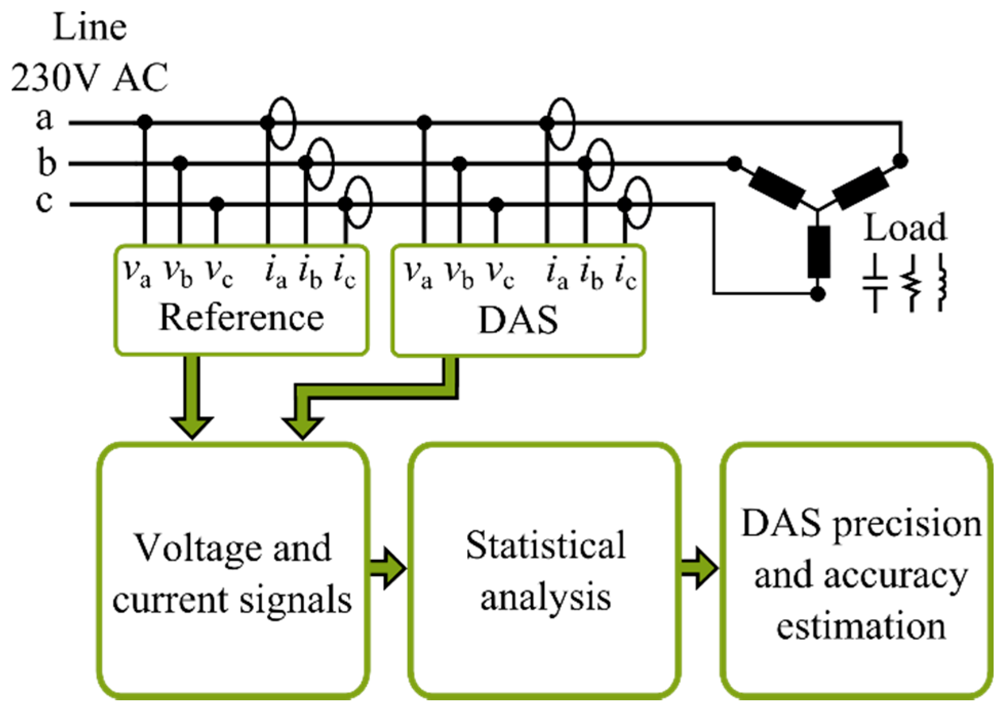
3.2. Validation
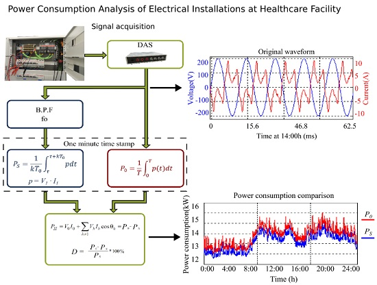
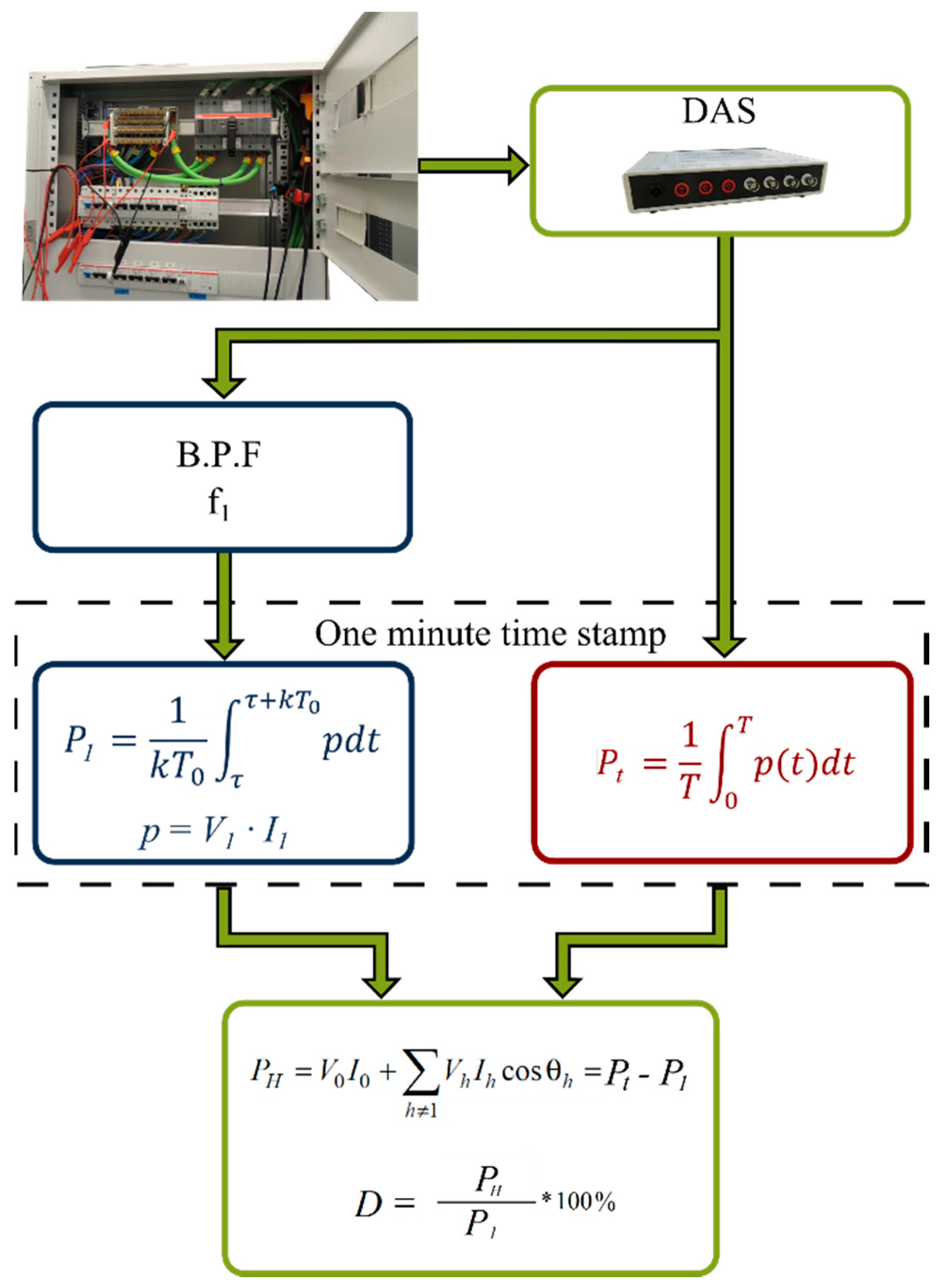
3.3 Proposed Methodology
4. Experimental Setup
4.1. Calibration
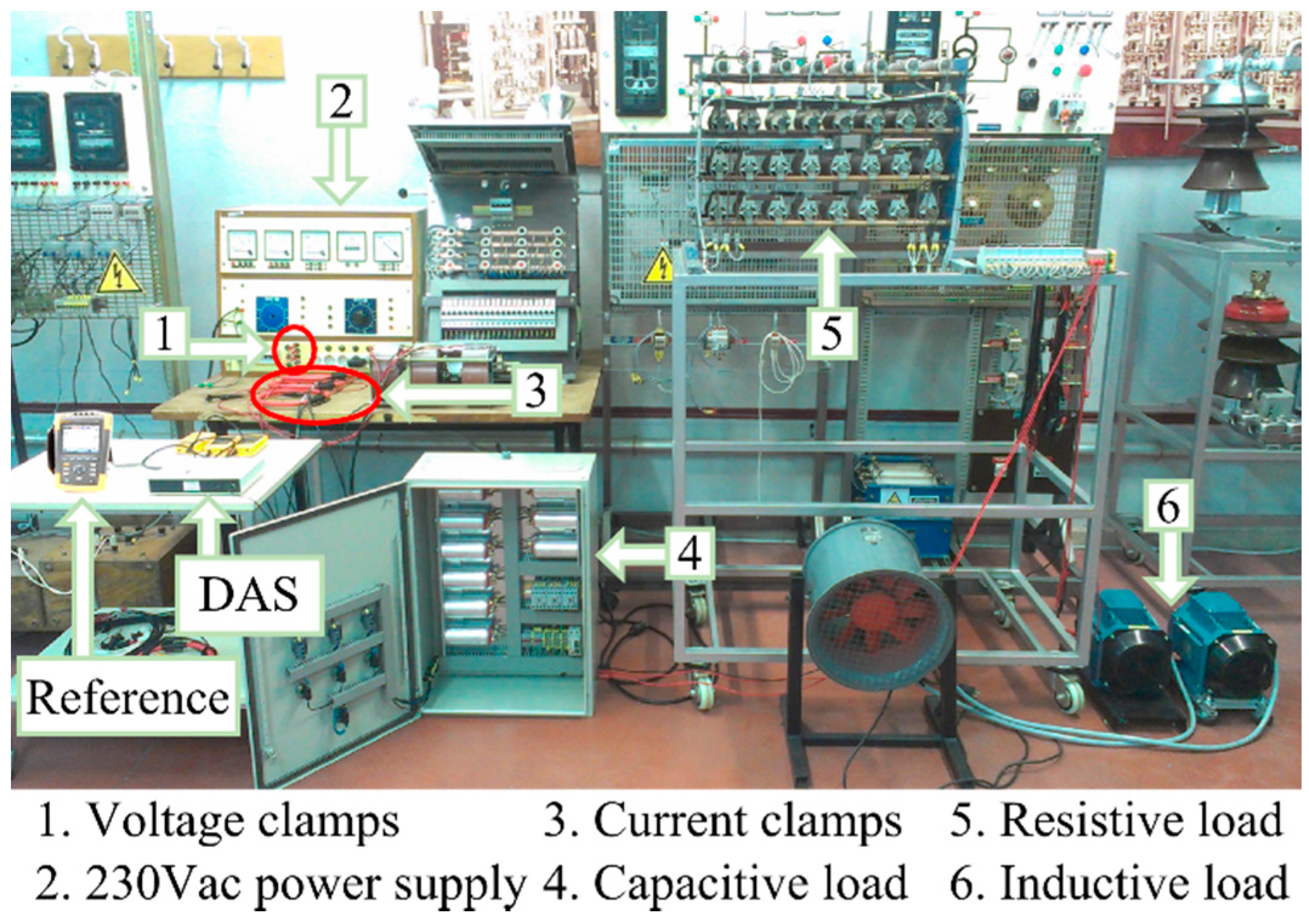
4.2. Validation
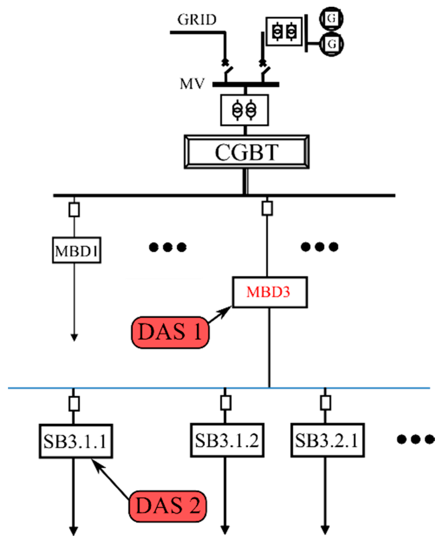
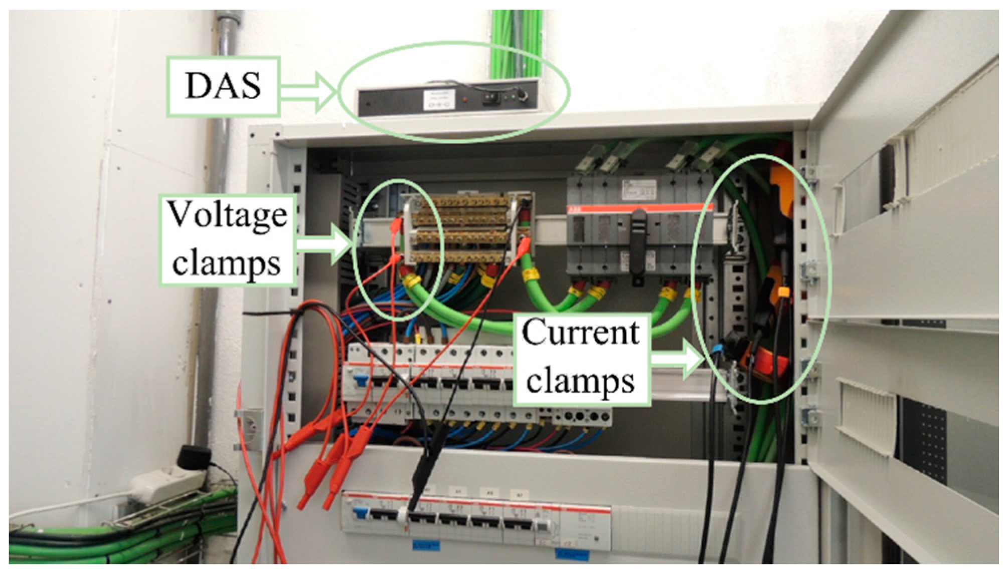
4.3. Healthcare Facility Data Acquisition
5. Results
5.1. Calibration Results
5.2. Validation Results
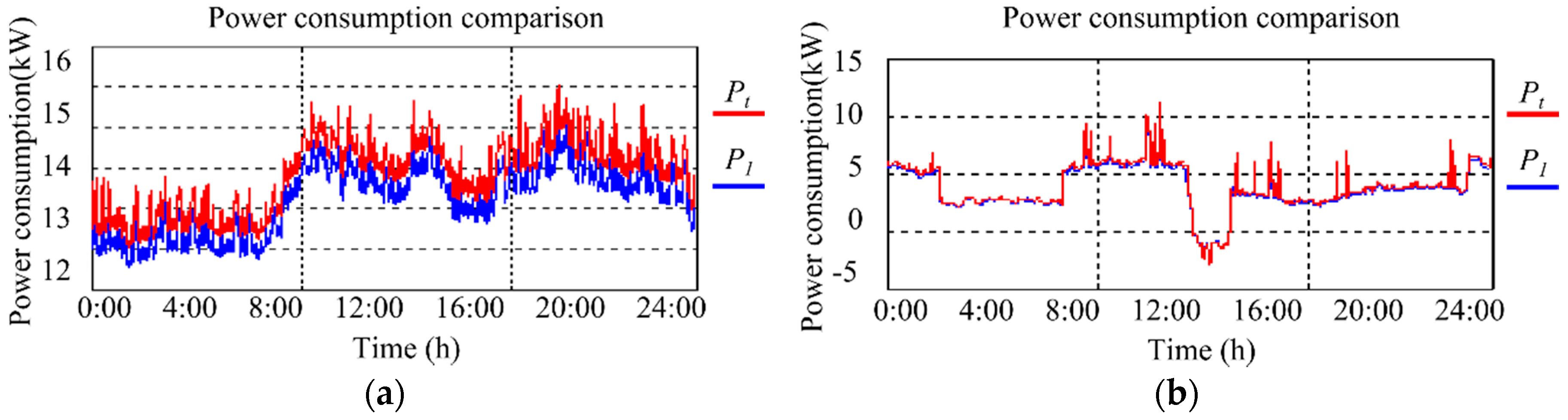
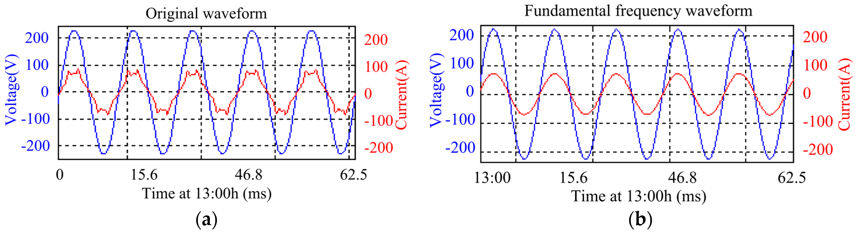
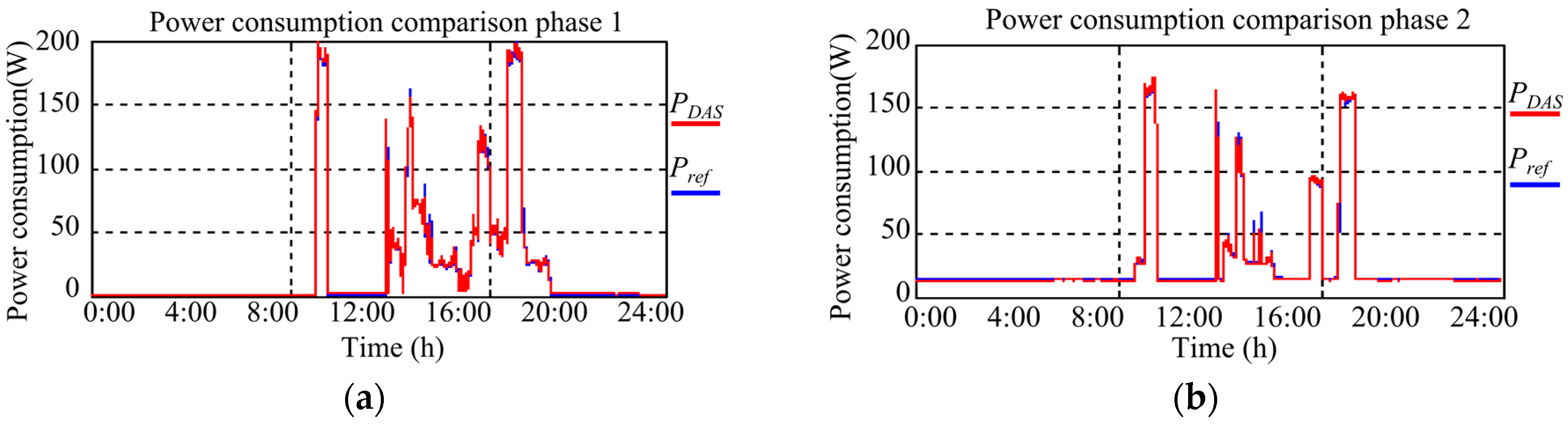
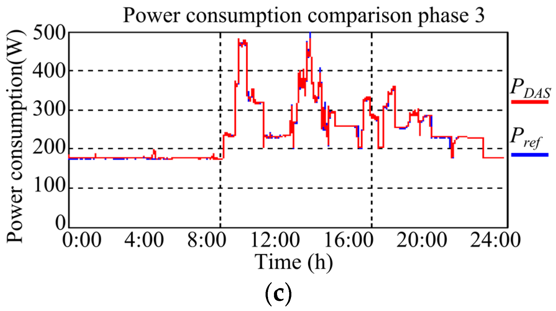
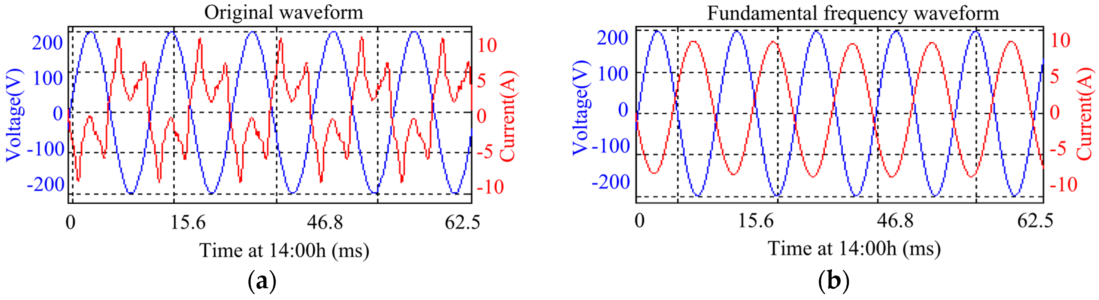
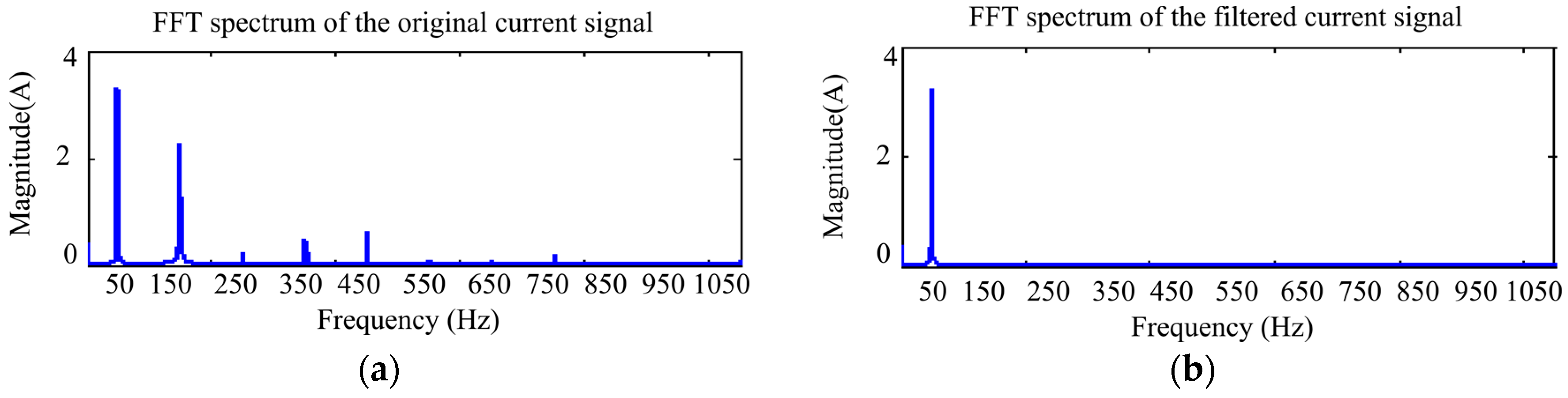
5.3. Healthcare Facility Data Acquisition Results
6. Conclusions
Acknowledgments
Author Contributions
Conflicts of Interest
References
- IEEE Standard Definitions for the Measurement of Electric Power Quantities under Sinusoidal, Nonsinusoidal, Balanced, or Unbalanced Conditions; IEEE Standard 1459-2010; The Institute of Electrial and Electronics Engineers: New York, NY, USA, 2010.
- IEC Electrical Installations of Buildings-Requirements for Special Installations or Locations—Medical Locations; IEC International Standard; International Electric Commission: Geneva, Switzerland, 2002.
- IEEE Recommended Practices for Electric Systems in Health Care Facilities; IEEE Standard 602; The Institute of Electrial and Electronics Engineers: New York, NY, USA, 1996.
- Ministry of Industry, Tourism and Trade. Installations in Areas of Public Assembly, Guide BT-28; Ministerio de la Industria Turismo y Comercio: Castilla y Leon, Spain, 2002. [Google Scholar]
- Escrivá, G.; Roldán, C.; de Jong, E. Nuisance tripping of residual current circuit breakers in circuits supplying electronic loads. Electr. Power Syst. Res. 2016, 131, 139–146. [Google Scholar] [CrossRef]
- Saxena, D.; Bhaumik, S.; Singh, S. Identification of multiple harmonic sources in power system using optimally placed voltage measurement devices. IEEE Trans. Ind. Electron. 2014, 61, 2483–2492. [Google Scholar] [CrossRef]
- Ye, G.; Xiang, Y.; Cuk, V.; Cobben, J. Harmonic disturbance location by applying Bayesian inference. Electr. Power Syst. Res. 2016, 140, 886–894. [Google Scholar] [CrossRef]
- Yang, K.; Bollen, M. Interharmonic currents from a Type-IV wind energy conversion system. Electr. Power Syst. Res. 2017, 143, 357–364. [Google Scholar] [CrossRef]
- Ferreira, D.; Nagata, E.; Ferreira, S.; de Seixas, J.; Duque, C.; Marques, C.; Guedes, J.; Cerqueira, A. Method based on independent component analysis for harmonicextraction from power system signals. Electr. Power Syst. Res. 2015, 119, 19–24. [Google Scholar] [CrossRef]
- Alahmad, M.; Wheeler, P.; Schwer, A.; Eiden, J.; Brumbaugh, A. A comparative study of three feedback devices for residential real-time energy monitoring. IEEE Trans. Ind. Electron. 2012, 59, 2002–2013. [Google Scholar] [CrossRef]
- Cherkassky, V.; Chowdhury, S.; Landenberg, V.; Tewari, S.; Bursch, P. Prediction of electric power consumption for commercial buildings. In Proceedings of the International Joint Conference on Neural Networks, San Jose, CA, USA, 31 July–5 August 2011.
- Ortega, S.; Manana, M. Energy research in airports: A review. Energies 2016, 82, 92–104. [Google Scholar] [CrossRef]
- Babar, M.; Javaid, N.; Ahmad, A.; Jamil, M.; Ali, Z.; Qasim, U.; Alrajeh, N. Energy optimization in smart homes using customer preference and dynamic pricing. Energies 2016, 74, 286–292. [Google Scholar]
- Anees, A.; Chen, Y.-P. True real time pricing and combined power scheduling of electric appliances in residential energy management system. Appl. Energy 2016, 165, 592–600. [Google Scholar] [CrossRef]
- Sugihuara, H.; Yokoyama, K.; Saeki, O.; Tsuji, K.; Funaki, T. Economic and efficient voltage management using customer-owned energy storage systems in a distribution network with high penetration of photovoltaic systems. IEEE Trans. Power. Syst. 2013, 28, 102–111. [Google Scholar] [CrossRef]
- Christiansen, N.; Kaltschmit, M.; Dzukowski, F.; Isensee, F. Electricity consumption of medical plug loads in hospital laboratories: Identification, evaluation, prediction and verification. Energy Build. 2015, 107, 392–406. [Google Scholar] [CrossRef]
- Bagnasco, A.; Fresi, F.; Saviozzi, M.; Silvestro, F.; Vinci, A. Electrical consumption forecasting in hospital facilities: An application case. Energy Build. 2015, 103, 261–270. [Google Scholar] [CrossRef]
- Boschiero, D. An energy and exergy analysis of a high-efficiency enginetrigeneration system for a hospital: A case study methodologybased on annual energy demand profiles. Energy Build. 2014, 76, 185–198. [Google Scholar]
- Zorita, A.; Fernández, M.; García, L.; Duque, O. A statistical modeling approach to detect anomalies in energetic efficiency of buildings. Energy Build. 2015, 110, 377–386. [Google Scholar] [CrossRef]
- Malhotra, R. Management of risk and economics of LV power system protection for industrial facilities. IEEE Trans. Ind. Appl. 2016, 52, 1308–1313. [Google Scholar]
- Nazmul, A.; Taib, S.; Shawal, M.; Ishak, D. A semi-automatic approach for thermographic inspection of electrical installations within buildings. Energy Build. 2012, 55, 585–591. [Google Scholar] [CrossRef]
- Fluke Corporation. Three-Phase Power Quality and Energy Analyzers; Fluke Co.: Everett, WA, USA, 2012. [Google Scholar]


© 2017 by the authors; licensee MDPI, Basel, Switzerland. This article is an open access article distributed under the terms and conditions of the Creative Commons Attribution (CC-BY) license (http://creativecommons.org/licenses/by/4.0/).
Share and Cite
Guillen-Garcia, E.; Zorita-Lamadrid, A.L.; Duque-Perez, O.; Morales-Velazquez, L.; Osornio-Rios, R.A.; Romero-Troncoso, R.D.J. Power Consumption Analysis of Electrical Installations at Healthcare Facility. Energies 2017, 10, 64. https://doi.org/10.3390/en10010064
Guillen-Garcia E, Zorita-Lamadrid AL, Duque-Perez O, Morales-Velazquez L, Osornio-Rios RA, Romero-Troncoso RDJ. Power Consumption Analysis of Electrical Installations at Healthcare Facility. Energies. 2017; 10(1):64. https://doi.org/10.3390/en10010064
Chicago/Turabian StyleGuillen-Garcia, Emmanuel, Angel L. Zorita-Lamadrid, Oscar Duque-Perez, Luis Morales-Velazquez, Roque Alfredo Osornio-Rios, and Rene De Jesus Romero-Troncoso. 2017. "Power Consumption Analysis of Electrical Installations at Healthcare Facility" Energies 10, no. 1: 64. https://doi.org/10.3390/en10010064