
Equivalence of Primary Control Strategies for AC and DC Microgrids †


Electronics and Computing Department, Mondragon Unibertsitatea, 20500 Mondragon, Spain
*
Author to whom correspondence should be addressed.
†
This paper is an extended version of our paper published in Proceedings of the 2016 IEEE 16th International Conference on Environment and Electrical Engineering (EEEIC), Firenze, Italy, 7–10 June 2016.
Energies 2017, 10(1), 91; https://doi.org/10.3390/en10010091
Submission received: 12 July 2016
/
Revised: 1 December 2016
/
Accepted: 4 January 2017
/
Published: 12 January 2017
(This article belongs to the Special Issue Selected Papers from 16 IEEE International Conference on Environment and Electrical Engineering (EEEIC 2016))
Abstract
:Microgrid frequency and voltage regulation is a challenging task, as classical generators with rotational inertia are usually replaced by converter-interfaced systems that inherently do not provide any inertial response. The aim of this paper is to analyse and compare autonomous primary control techniques for alternating current (AC) and direct current (DC) microgrids that improve this transient behaviour. In this context, a virtual synchronous machine (VSM) technique is investigated for AC microgrids, and its behaviour for different values of emulated inertia and droop slopes is tested. Regarding DC microgrids, a virtual-impedance-based algorithm inspired by the operation concept of VSMs is proposed. The results demonstrate that the proposed strategy can be configured to have an analogous behaviour to VSM techniques by varying the control parameters of the integrated virtual-impedances. This means that the steady-state and transient behaviour of converters employing these strategies can be configured independently. As shown in the simulations, this is an interesting feature that could be, for instance, employed for the integration of different dynamic generation or storage systems, such as batteries or supercapacitors.
1. Introduction
The increasing penetration of distributed generation (DG) systems is shifting the current electric grid from the classical top-down structure to a decentralized one. Several challenges arise from this topological change, as the electric grid was not originally designed to handle the dispersed and intermittent nature of DG systems. In this context, microgrids—low-scale smart distribution electric grids composed by generation, energy storage systems (ESSs), and loads—are arising as one of the most promising alternatives for DG integration [1,2]. Thanks to the ESSs and the advanced control strategies they include, microgrids are capable of managing DG systems in an efficient and reliable way, and can operate both connected to or isolated from the main grid. However, control strategies must address several tasks—e.g., islanding/reconnection process, frequency/voltage stable regulation, harmonic compensation, etc.—and therefore, it is a widely researched field in the literature [3,4,5,6,7,8].
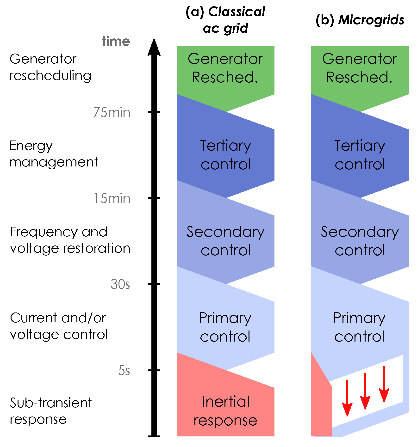
One of the most crucial challenges is to ensure a robust regulation of frequency and/or voltage, which is strongly deteriorated by the fact that most DG and ESSs are interfaced by a power converter, rather than being directly connected to the microgrid [9,10]. In the classical AC network, the inherent inertia of rotating synchronous generators acts as a power buffer to handle transient demand or generation variations and reduce frequency and voltage disturbances [9,11]; i.e., the inertial response opposes power variations in the grid (Figure 1a).
However, in microgrids, classical rotating generators are replaced by converter-interfaced DG and ESSs, significantly reducing the inertial response [12]. Consequently, these converters must handle the transient power variations in order to keep the frequency and voltage within the limits, and this is usually carried out with their primary or low-level control strategies (Figure 1b). A common approach is to employ autonomous controllers to avoid a communication network that would increase the overall cost and would reduce the reliability and robustness of the system.
Depending on the characteristics of the microgrid, different primary control techniques must be employed to provide this inertial response. Usually, three different microgrid types are distinguished based on the nature of their current: alternating current (AC), direct current (DC) or hybrid AC/DC. Most of the actual microgrids are AC-based networks, but DC and hybrid AC/DC ones are arising as an interesting solution thanks to the benefits they provide over purely AC ones [13]—e.g., no need for synchronization, no reactive power circulation, less AC–DC–AC conversion stages, etc.
Regarding AC microgrids, the emulation of synchronous generators in the primary control level is one of the most interesting strategies to improve the inertial behaviour of the network. This control technique is also known as a virtual synchronous machine (VSM) [14,15] or synchronverter [16,17]. In the literature, several studies can be found where this type of technique is employed; for instance, D’Arco et al. carry out a review of some of the most relevant VSM techniques in [18]. In this review, several VSMs are identified and classified based on the order of the models they include. One of the advantages of employing this technique is that the dynamic behaviour—transient and steady-state—of the converters can be adapted by modifying the control parameters of emulated inertia and damping factor. In addition, this technique enables the autonomous operation of multiple parallel converters that participate in the regulation of the microgrid frequency and voltage. These reasons have led many researchers to employ VSM techniques for different applications. For instance, Hogan et al. demonstrated the integration of a 15 kVA voltage-source converter on a microgrid platform employing a VSM [19]. According to the authors, this technique allows not only the performance of active power control, but it also provides frequency support during transients. VSMs have also been proposed as an interesting approach for the provision of different vehicle-to-grid services, as analysed by Suul et al. in [20]. In addition, these strategies are emerging as a useful tool to improve the inertial response of wind-power systems, an example of which can be seen in the study carried out by Wang et al. in [21].
The case of DC microgrids is different, as there are no rotating devices with mechanical inertia directly connected to these systems. Moreover, in DC systems, active power variations are handled by regulating the voltage and not the frequency, as in AC ones. Consequently, other primary control strategies need to be employed in order to improve the transient behaviour of the DC network. One of the most extended trends is the use of virtual-impedances in the control loop [22,23,24]. As in the VSM control for AC microgrids, the value of these impedances can be adapted in order to modify the dynamic behaviour of converters under power variations. In [22], Wang et al. carry out a review of some of the most typical virtual-impedance control techniques. Although this review is carried out for AC systems, the same concepts can be applied to DC microgrids. For instance, a virtual-impedance technique was proposed by Lu et al. in [23] to improve the stability of a DC microgrid. A virtual-capacitor was used for similar purposes by Zhong et al. and Magne et al. in [25,26], respectively. Other approaches employ virtual-capacitors for the integration of different types of ESSs on a DC microgrid [27]. Although these strategies improve the transient response and stability of DC microgrids, their control is usually composed of cascaded voltage and current proportional-integral (PI) regulators that have a direct impact on the response of converters under sudden power variations.
The main contribution of this paper is the development and comparative study of a virtual-impedance control strategy for DC microgrids that reproduces the behaviour of VSMs, based on the study carried out in [28]. Unlike classical approaches, this technique does not include any cascaded PI regulator. Instead, the transfer functions of the virtual-impedance are directly integrated for the calculation of the reference voltage of converters, avoiding the delay of classical regulators. As the proposed technique is based on VSMs, in Section 2, their operation principle is first reviewed. In this section, their behaviour for different power variations and control parameters is analysed. Based on this operation concept, in Section 2, an equivalent technique is proposed for the voltage regulation of DC microgrids; its transient and steady-state behaviour is examined, and a comparative evaluation is carried out to highlight the analogies with VSM techniques. The paper concludes with the most important remarks of the analysis.
2. AC Microgrid Primary Control with Inertia Emulation
Synchronous generators driven by thermal, nuclear, or hydroelectric power plants are responsible for regulating the frequency and voltage in classical AC grids. A higher number of these generators means more rotational inertia in the network, which is directly reflected in the response of the grid over power variations. If an electric grid contains a high value of inertia, the voltage and frequency will suffer small variations under sudden power variations. On the contrary, if this inertia is low, the voltage or frequency might experience high deviations, which can lead to the malfunction or damage of the systems connected to the network or cause a chain disconnection of devices.
In an AC microgrid, the number of these generators is considerably reduced and replaced by converter-interfaced DG and ESSs, exposing the system to disturbances. A possible solution for the improvement of this transient response is the emulation of inertia in the control of these converters; for example, employing an autonomous VSM technique [14,15,16,17,18]. These control algorithms are based on the swing equation of synchronous generators connected to the conventional electric grid, which can be obtained from the following motion equation [29]:
where J is the combined inertia of the turbine and the generator, the angular speed of the rotor, the accelerating torque, the mechanical torque, and the electromagnetic torque. As can be noticed, an imbalance between the mechanical and electrical torque causes the acceleration or deceleration of the synchronous machine. Depending on the value of inertia, the generator will accelerate differently, opposing more or less to variations in the network. Usually, a damping torque component is added in the motion equation which is proportional to the speed deviation of the motor—i.e., the difference between the generator speed and its rated value.
where represents the damping factor and δ the angular position of the rotor.
This equation represents the fundamentals of the motion of a synchronous generator, and it is also named a swing equation because it represents the swings in the angle of the rotor (δ) when there is a torque imbalance [29]. As can be deduced, the integration of more synchronous generators leads to an increment of the total kinetic energy stored (Equation (3)), which improves the transient response of the network.
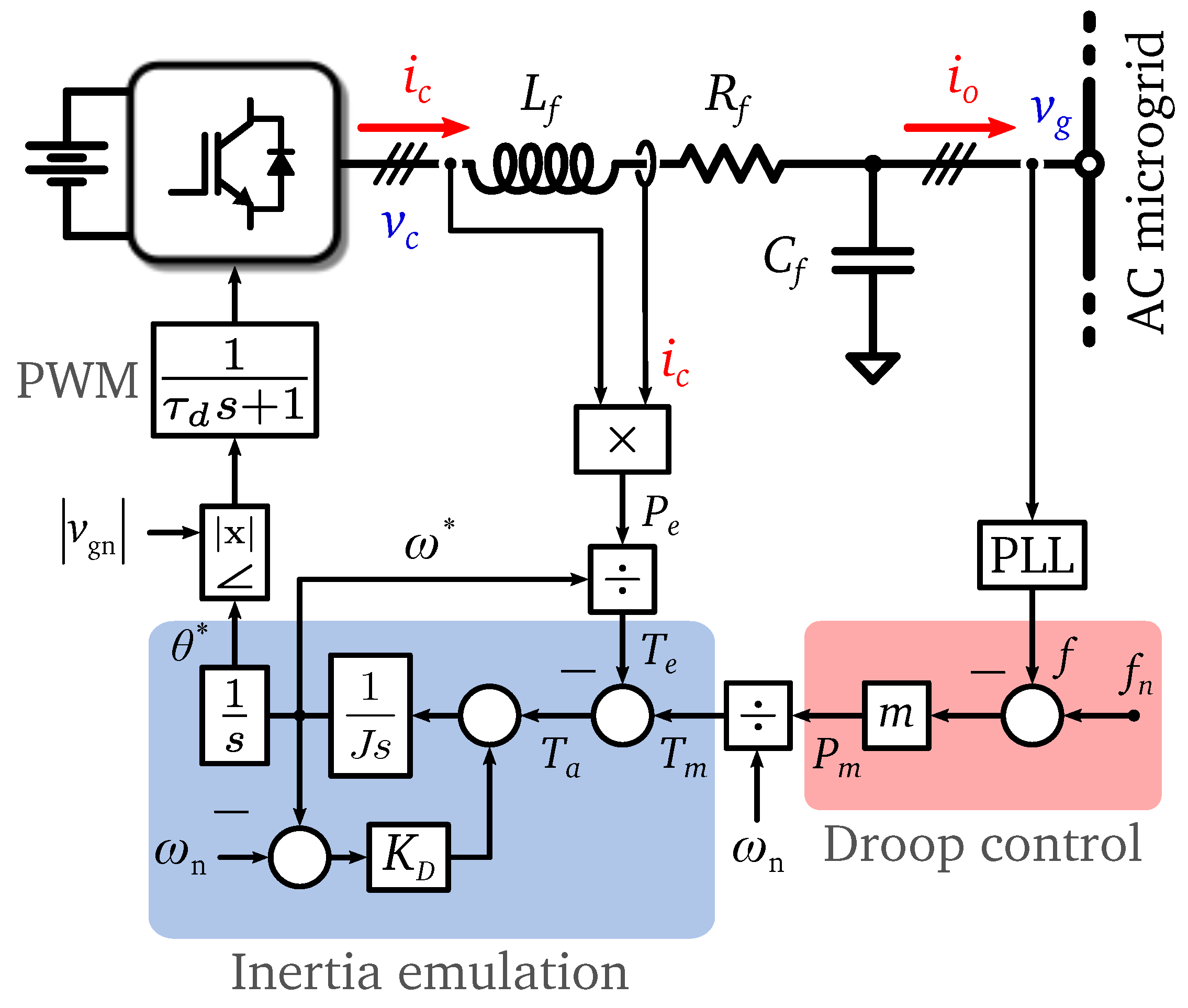
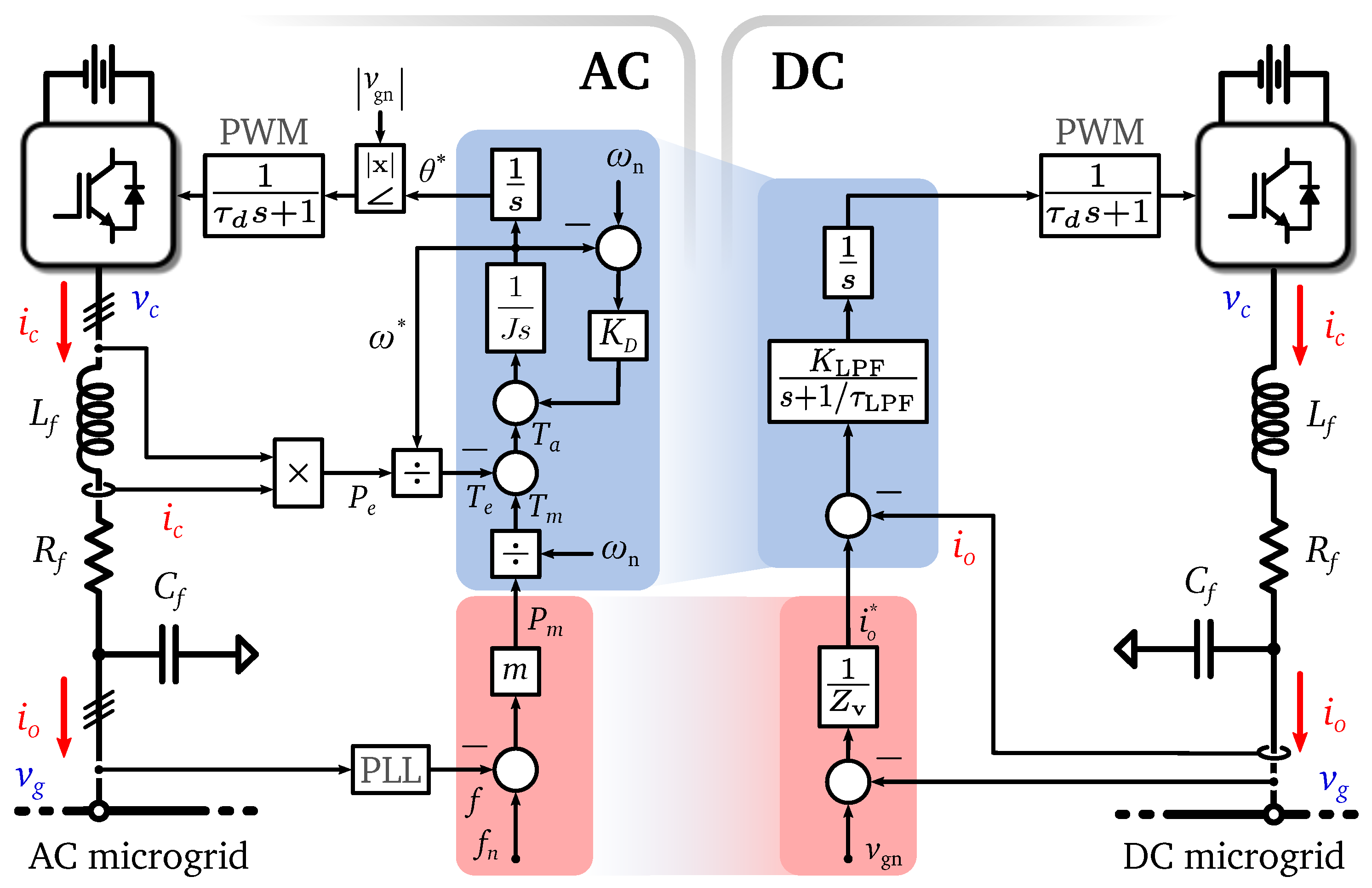
The VSM control technique that has been employed in this section is represented in Figure 2. The frequency reference is directly obtained from the implemented swing equation, where J is the emulated inertia and the emulated damping factor. Moreover, as is done with classical synchronous generators, a droop-based governor has been used to determine the steady-state operation point of the converter. Although it can be noticed that the droop governor (m·, ) and the damping component of the inertia emulation (·, ) are equivalent, they have been kept decoupled for the sake of clarity. In a classical synchronous machine, the effect of the damping factor is much lower than the impact of the droop control, and the main purpose in this case has been to maintain the model as close as possible. For the same reason, no voltage or current PI regulators have been included, avoiding any delay in the control response.
It must be mentioned that in this case, it is assumed that the circulation of reactive power is very low, and therefore the voltage amplitude is kept constant. In addition, a one switching cycle delay () has also been introduced in the system to model the effect of the pulse-width modulator (PWM). Regarding the frequency measurement, the effect of the phase-locked loop (PLL) has been also included in the model.
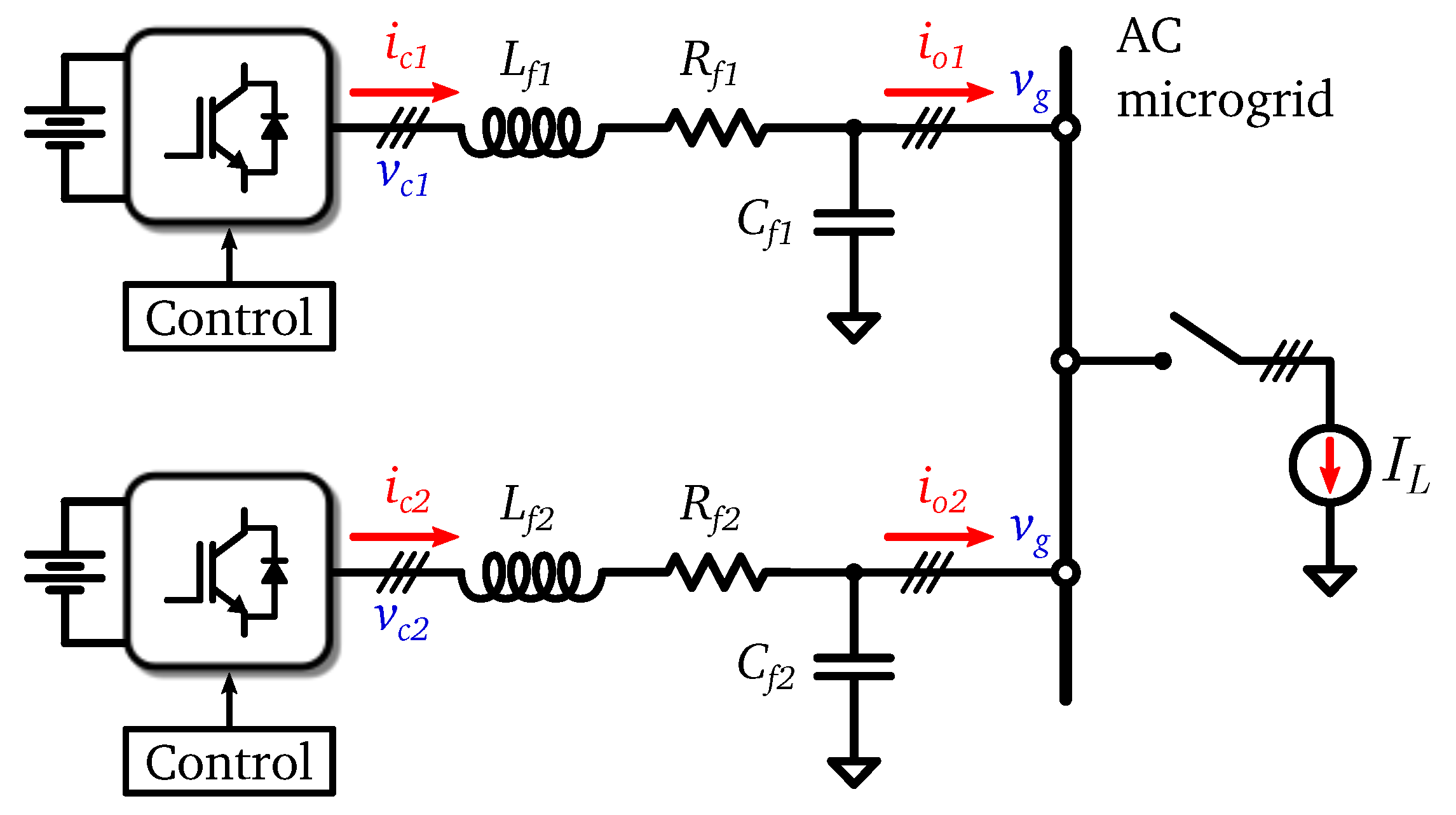
Several simulations have been carried out in the Matlab/Simulink® environment in order to verify the behaviour of the VSM technique in an isolated microgrid environment. The simulation scenario is composed by two parallel converters—modelled as a controlled voltage source—regulating the frequency of a three-phase AC microgrid (Figure 3). This configuration allows the study of not only the transient and steady-state operation, but also the power sharing of converters with the implemented VSM technique.
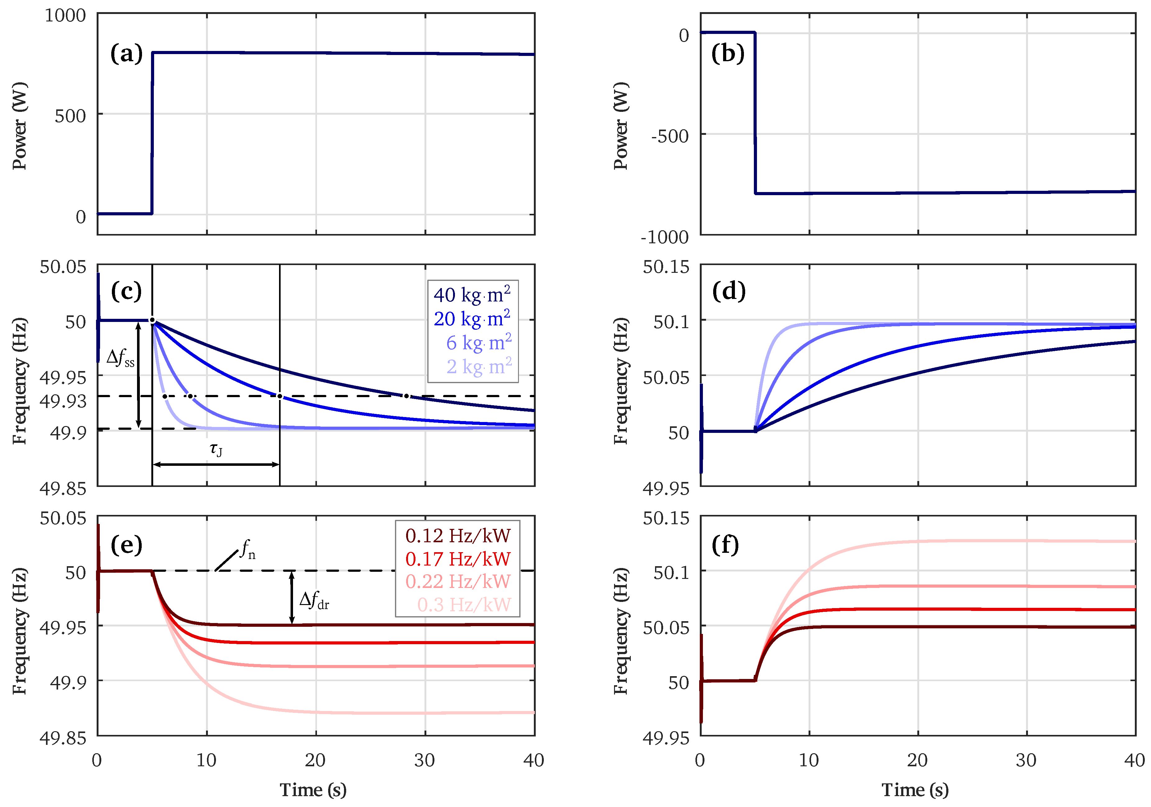
The microgrid is modelled as a controlled current source in order to emulate different power variations. On one hand, a sudden demand variation has been emulated by applying a positive load current step (Figure 4a) at the instant t = 5 s. The results of these simulations are collected on the left side of Figure 4. Similarly, a negative current step has been applied in order to emulate an increment in the generation (Figure 4b). These results are illustrated on the right side of Figure 4. The most relevant parameters employed in the simulations can also be observed in Table 1.
2.1. Variation of Emulated Inertia
The first set of tests consist of emulating different values of inertia in the VSM control algorithms of the two converters in order to observe its impact on the transient response of the AC microgrid. It must be noted that in this case, both parallel converters are configured identically to neglect the effect of other system parameters in the results. In this case, the droop coefficient has been kept constant for all the simulations with a value of 0.25 Hz/kW.
The curves in Figure 4c,d shows that an increment of the emulated inertia reduces the decay rate of the frequency when the load is connected. The same behaviour is observed for a positive and negative current step.
Based on these results, Table 2 collects the time that the frequency takes to reach the 63.2% of the steady-state deviation () after a power variation, which is named .
These results demonstrate that the dynamics of regulating converters can be adapted under different power variations, meaning that the transient behaviour of the microgrid frequency can be improved by simply varying the inertia emulated in the control strategy.
2.2. Variation of Droop Slopes
The simulations of this section are carried out by varying the droop slopes of the two parallel converters in order to modify their steady-state operation point. This type of regulation is widely employed with classical synchronous generators, because it is a simple way of sharing the power variations without any type of communication between parallel systems. The virtual inertia in this case is set to 60 kg·m2 for all of the simulations.
Figure 4e,f shows that a reduction of the droop slope shifts the steady-state frequency deviation of the network. By reducing this parameter, the sensitivity of converters under power variations is increased; i.e., more power is transmitted for a lower frequency variation. The values of the steady-state frequency deviation () for different droop slopes are collected in Table 3.
These results verify that the steady-state point of operation of converters can be shifted with the droop slopes. The simulations carried out up to this point demonstrate that with VSM techniques, the transient and steady-state behaviour of converters can be modified independently. This is an interesting feature of VSM techniques—for instance, for the integration of DG and ESSs of different natures in the microgrid—providing a high flexibility. The next section provides an example of this mode of operation.
2.3. Different Dynamic Parallel Converters
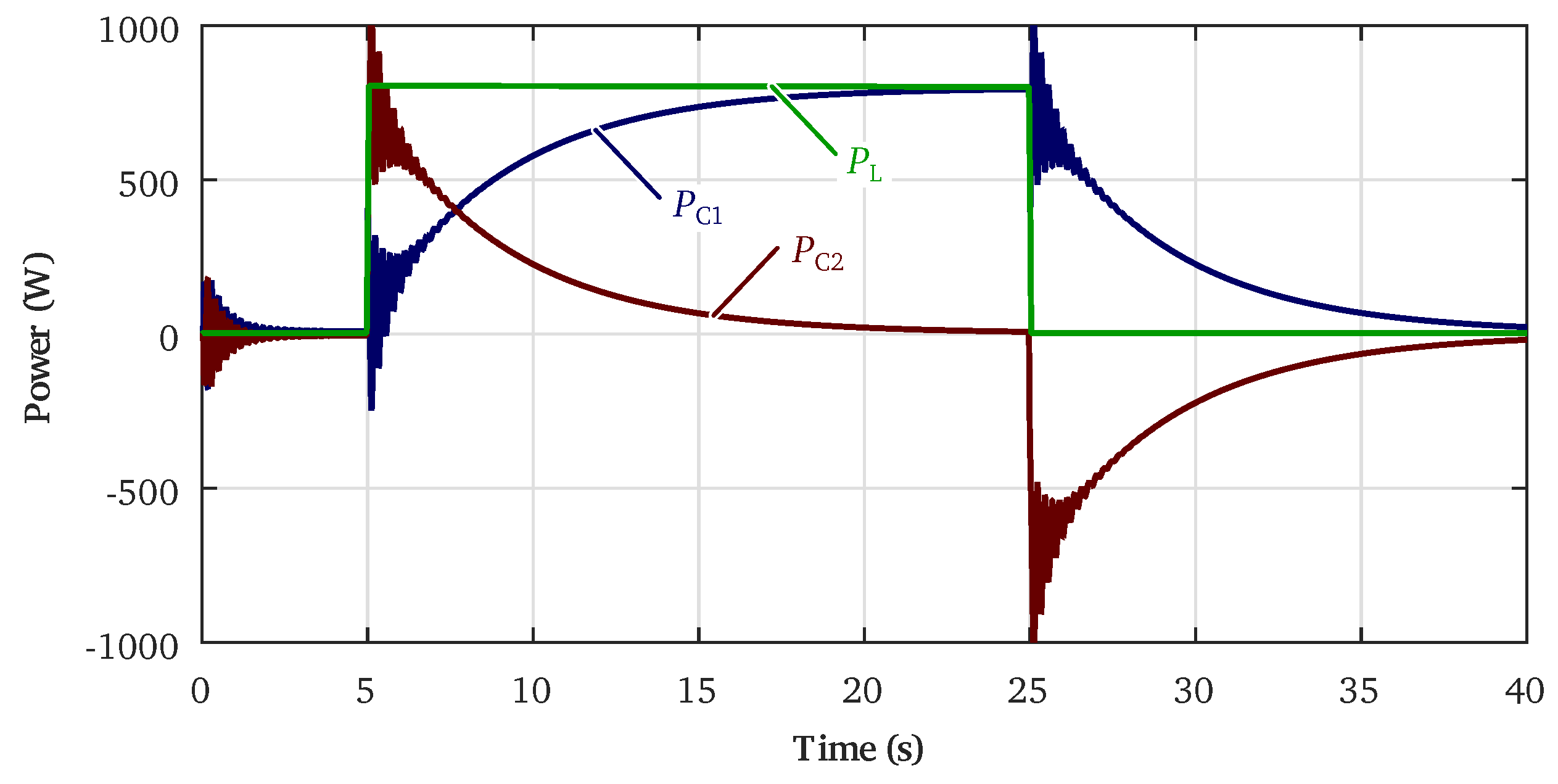
In this case, the emulated inertia and droop slopes have been adapted so that one of the converters provides most of the power during the transient interval of a power variation, and the other supplies power in the steady-state range. This could be applied, for example, in a hybrid ESS composed of a group of batteries and supercapacitors, in order to avoid a premature aging of the battery pack due to power peaks.
The parameters of the converter with slowest dynamics are = 0.033 Hz/kW and kg·m2. Regarding the converter with highest dynamics, the droop and virtual inertia values have been set to = 0 Hz/kW and kg·m2. By making the droop slope of the highest dynamic converter zero, this system provides no power in the steady-state interval. However, its high value of virtual inertia means that this system has to handle most of the power variation during transients.
This phenomenon can be clearly appreciated in Figure 5 for a load step change. During the transient interval, the second converter handles most of the power, and then in the steady-state range, the first converter provides the power required by the load.
3. DC Microgrid Primary Control with Virtual-Impedance
The control of DC microgrids is different from the previous one, because power variations are managed by regulating the voltage and not the frequency. Moreover, systems with rotating inertia cannot be directly connected to DC systems. Instead, the energy of DC grids mainly depends on the capacitors included in the system. The relationship between AC and DC networks can be clearly seen by comparing the equation of the kinetic energy stored in the rotating inertia of AC systems (Equation (3)) and the equation of the energy stored in the capacitors:
As can be noticed, in AC systems, the stored energy is dependent on the frequency (Equation (3)) whereas in DC systems, the stored energy depends on the voltage level. This means that in order to reproduce the behaviour of VSM techniques in DC microgrids, it is necessary to emulate the response of a capacitor directly connected to the system.
In this paper, a virtual-impedance-based control technique is proposed to reproduce this behaviour, which is inspired by the VSM strategy analysed in Section 2. Figure 6 illustrates the already-shown VSM technique and the proposed strategy for DC microgrids, highlighting their most relevant similarities. In the latter, the converter current reference is obtained from the bus voltage and a virtual-impedance (), which is equivalent to the droop slope implemented in the previous VSM strategy. This means that the value of the virtual-impedance will determine the steady-state operation point of the converter. In this case, the virtual impedance is resistive to reproduce a proportional (P) gain, but more complex transfer functions could be employed to adapt the behaviour of the converter and provide other features [23].
The lower level regulator of the proposed technique is inspired by the inertia emulation carried out at VSMs. After some rearrangements, it can be observed that the simplified transfer function of the inertia emulation is very similar to a low-pass filter (LPF) or an RC circuit with an additional integration term:
where is the gain of the filter and its time constant.
From this analysis, it can be noticed that the inertial response can be reproduced at DC microgrids by employing a control filter. Even though this technique and the VSM technique cannot be directly compared due to the differences of AC and DC grids, in the following sections, it is demonstrated that a similar behaviour can be reproduced by employing the proposed technique.
The simulation scenario is very similar to the one shown in Figure 3, but the three-phase AC grid is replaced with a single-phase DC one. The most relevant simulation parameters are collected in Table 4.
Similar to the simulations carried out in Section 2, a positive and negative power variation has been applied in order to test the behaviour of the proposed control strategy. The results for a load increment are shown on the left side of Figure 7, and the curves for a generation increment on the right side.
3.1. Variation of the Low-Pass Filter Gain
As can be deduced from (5), the low-pass filter gain is inversely proportional to the emulated inertia (J), so an increment of this gain would be equivalent to a reduction of the inertial response in the system. In these simulations, the virtual-impedance has been set to 3 Ω.
This behaviour can be observed in Figure 7c,d, where it is illustrated how the transient response of the microgrid voltage is slowed down for lower values of . Therefore, it is shown that this technique is analogous to the emulation of inertia in VSM techniques, which means that the transient response of the converter can be adapted by changing the value of the LPF gain.
In this case—as was done in Section 2.1—a time constant () has been obtained for each curve in order to quantify how the LPF gain affects the dynamics of the voltage. This time constant is measured when the voltage deviation is 63.2% of the steady-state voltage deviation ( ≃ 377 V), which in this case is 378 V. The numerical results are collected in Table 5.
3.2. Variation of the Virtual-Impedance
The virtual-impedance is employed to modify the steady-state operation point of the converters, so it is equivalent to the droop governor included in the VSM technique. For the following tests, the LPF gain has been set to 60.
The curves illustrated in Figure 7e,f corroborate that—as with the droop slope—a reduction of the virtual resistance implies a decrease of the voltage variation in the steady-state interval. The steady-state voltage variations for each virtual-impedance value are shown in Table 6.
These results show that the adaptation of the steady-state and transient behaviour of converters employing the proposed technique is decoupled, so they can be modified independently, as has been done with the VSM technique. This feature enables the integration of different dynamic systems in the microgrid, as was shown in Section 2.3. The following section is an example of this operation mode.
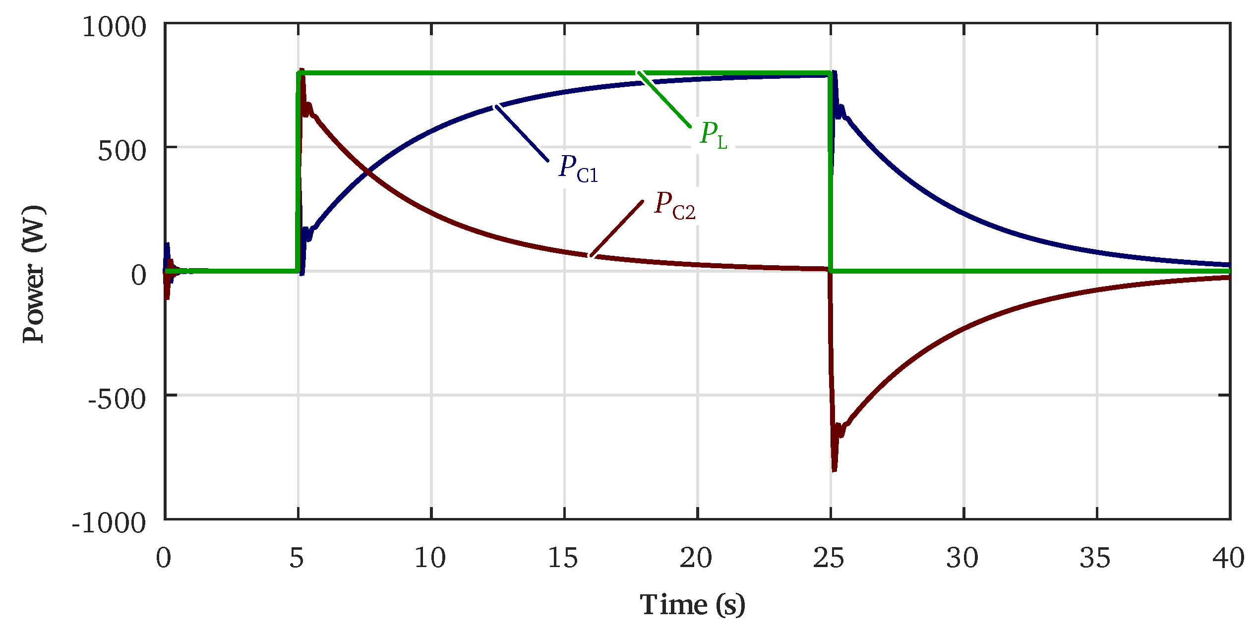
3.3. Different Dynamic Control for Parallel Converters
In this case, the virtual-impedances and LPF gains have been chosen to reproduce a behaviour similar to that seen in Section 2.3. The parameters of the first converter are configured as ZV1 = 0.2 Ω and , and in the second converter, they are set to ZV2 = 1 kΩ and .
Figure 8 illustrates the power supplied by each converter for a sudden load variation. The behaviour of the converters employing the proposed technique shows that virtual-impedance-based algorithms can mimic the concept of operation of VSM techniques in DC microgrids.
4. Conclusions
The frequency and voltage regulation of AC and DC microgrids is a challenging task that is being widely studied in the literature. This is mainly due to the fact that, in microgrids, classical synchronous generators with rotational inertia are replaced by converter-interfaced DG or ESSs that do not inherently contribute in the dynamic response of the system.
This paper has studied two different control techniques that mimic the behaviour of the conventional AC grid by emulating the dynamic response of synchronous generators.
One of them is the already-known VSM technique employed at AC microgrids, which integrates the characteristic swing equation of synchronous generators to carry out the frequency regulation. The results obtained in this paper clearly show that this type of control technique can be used for the improvement of the transient response of AC microgrids under power variations. The emulated inertia can be adapted to decrease the frequency decay rate under power variations. For instance, the value of the time constant can be increased from 1.97 s to 19.54 s by increasing the value of the emulated inertia J from 2 kg·m2 to 40 kg·m2. In addition, the voltage steady-state deviation can be reduced from 0.13 Hz to 0.049 Hz by changing the droop slope from 0.3 Hz/kW to 0.12 Hz/kW. These results demonstrate that the steady VSM techniques can be configured for the integration of different dynamic DG or ESSs, as the steady-state and transient response of converters can be modified independently. This is an interesting feature, for instance, for the integration of hybrid ESSs such as batteries or supercapacitors, increasing the flexibility of the system.
On the other hand, a virtual-impedance-based control strategy has been proposed for the voltage regulation of DC microgrids. This technique is analogous to the VSM strategy, meaning that the steady-state and transient behaviour of converters can be adapted by varying the control parameters. The results show that the voltage decay rate can be slowed down by modifying the LPF gain . As an example, the time constant can be increased from 4.36 s to 30.5 s by increasing the value of from 5 to 70. Moreover, the steady-state voltage deviation can be adapted depending on the virtual-impedance value. In the simulations, it was shown that can be reduced from 4.19 V to 1.05 V by changing from 4 Ω to 1 Ω. It has also been verified that the proposed technique can be configured to integrate different dynamic generation or storage systems, as in the VSM technique.
Throughout the paper the most important equivalences of VSMs and the proposed virtual-impedance technique have been highlighted. This demonstrates that an analogous behaviour can be obtained at AC and DC microgrids in terms of the inertial response of converters under power variations.
Acknowledgments
This work has been partially funded by a predoctoral grant of the Basque Government (PRE_2015_2_0074) and a grant from the Spanish Ministry of Economy and Competitiveness under the call “Retos Colaboración” (GEISER, RTC-2014-2764-3).
Author Contributions
All authors contributed equally to this work.
Conflicts of Interest
The authors declare no conflict of interest.
References
- Farhangi, H. The path of the smart grid. IEEE Power Energy Mag. 2010, 8, 18–28. [Google Scholar] [CrossRef]
- Nordman, B.; Christensen, K.; Meier, A. Think Globally, Distribute Power Locally: The Promise of Nanogrids. Computer 2012, 45, 89–91. [Google Scholar] [CrossRef]
- Han, H.; Hou, X.; Yang, J.; Wu, J.; Su, M.; Guerrero, J.M. Review of power sharing control strategies for islanding operation of AC microgrids. IEEE Trans. Smart Grid 2016, 7, 200–215. [Google Scholar] [CrossRef]
- Vandoorn, T.; De Kooning, J.; Meersman, B.; Vandevelde, L. Review of primary control strategies for islanded microgrids with power-electronic interfaces. Renew. Sustain. Energy Rev. 2013, 19, 613–628. [Google Scholar] [CrossRef]
- Gopalan, S.A.; Sreeram, V.; Iu, H.H.C. A review of coordination strategies and protection schemes for microgrids. Renew. Sustain. Energy Rev. 2014, 32, 222–228. [Google Scholar] [CrossRef]
- Unamuno, E.; Barrena, J.A. Hybrid ac/dc microgrids—Part II: Review and classification of control strategies. Renew. Sustain. Energy Rev. 2015, 52, 1123–1134. [Google Scholar] [CrossRef]
- Mehrasa, M.; Pouresmaeil, E.; Jørgensen, B.N.; Catalão, J.P. A control plan for the stable operation of microgrids during grid-connected and islanded modes. Electr. Power Syst. Res. 2015, 129, 10–22. [Google Scholar] [CrossRef]
- Mehrasa, M.; Pouresmaeil, E.; Mehrjerdi, H.; Jørgensen, B.N.; Catalão, J.P. Control technique for enhancing the stable operation of distributed generation units within a microgrid. Energy Convers. Manag. 2015, 97, 362–373. [Google Scholar] [CrossRef]
- Uriarte, F.M.; Smith, C.; Vanbroekhoven, S.; Hebner, R.E. Microgrid Ramp Rates and the Inertial Stability Margin. IEEE Trans. Power Syst. 2015, 30, 3209–3216. [Google Scholar] [CrossRef]
- Delille, G.; François, B.; Malarange, G.; Francois, B.; Malarange, G.; François, B.; Malarange, G. Dynamic frequency control support by energy storage to reduce the impact of wind and solar generation on isolated power system’s inertia. IEEE Trans. Sustain. Energy 2012, 3, 931–939. [Google Scholar] [CrossRef]
- Ulbig, A.; Rinke, T.; Chatzivasileiadis, S.; Andersson, G. Predictive control for real-time frequency regulation and rotational inertia provision in power systems. In Proceedings of the 52nd IEEE Conference on Decision and Control, Firenze, Italy, 10–13 December 2013.
- Tielens, P.; Van Hertem, D. The relevance of inertia in power systems. Renew. Sustain. Energy Rev. 2016, 55, 999–1009. [Google Scholar] [CrossRef]
- Unamuno, E.; Barrena, J.A. Hybrid ac/dc microgrids—Part I: Review and classification of topologies. Renew. Sustain. Energy Rev. 2015, 52, 1251–1259. [Google Scholar] [CrossRef]
- D’Arco, S.; Suul, J.A.; Fosso, O.B. Small-signal modeling and parametric sensitivity of a virtual synchronous machine in islanded operation. Int. J. Electr. Power Energy Syst. 2015, 72, 3–15. [Google Scholar] [CrossRef] [Green Version]
- D’Arco, S.; Suul, J.A.; Fosso, O.B. Control system tuning and stability analysis of Virtual Synchronous Machines. In Proceedings of the 2013 IEEE Energy Conversion Congress and Exposition, Denver, CO, USA, 5–19 September 2013.
- Zhong, Q.-C.; Nguyen, P.-L.; Ma, Z.; Sheng, W. Self-Synchronized Synchronverters: Inverters without a Dedicated Synchronization Unit. IEEE Trans. Power Electr. 2014, 29, 617–630. [Google Scholar] [CrossRef]
- Zhong, Q.C.; Weiss, G. Synchronverters: Inverters That Mimic Synchronous Generators. IEEE Trans. Ind. Electr. 2011, 58, 1259–1267. [Google Scholar] [CrossRef]
- D’Arco, S.; Suul, J.A. Virtual synchronous machines—Classification of implementations and analysis of equivalence to droop controllers for microgrids. In Proceedings of the 2013 IEEE Grenoble Conference, Grenoble, France, 16–20 June 2013.
- Hogan, D.J.; Gonzalez-Espin, F.; Hayes, J.G.; Lightbody, G.; Albiol-Tendillo, L.; Foley, R. Virtual synchronous-machine control of voltage-source converters in a low-voltage microgrid. In Proceedings of the 18th European Conference on Power Electronics and Applications (EPE’16 ECCE Europe), Geneva, Switzerland, 5–8 September 2016.
- Suul, J.A.; DArco, S.; Guidi, G. Virtual synchronous machine-based control of a single-phase bi-directional battery charger for providing vehicle-to-grid services. IEEE Trans. Ind. Appl. 2016, 52, 3234–3244. [Google Scholar] [CrossRef]
- Wang, S.; Hu, J.; Yuan, X. Virtual synchronous control for grid-connected DFIG-based wind turbines. IEEE J. Emerg. Sel. Top. Power Electr. 2015, 3, 932–944. [Google Scholar] [CrossRef]
- Wang, X.; Li, Y.W.; Blaabjerg, F.; Loh, P.C. Virtual-Impedance-Based Control for Voltage-Source and Current-Source Converters. IEEE Trans. Power Electr. 2015, 30, 7019–7037. [Google Scholar] [CrossRef]
- Lu, X.; Sun, K.; Guerrero, J.M.; Vasquez, J.C.; Huang, L.; Wang, J. Stability Enhancement Based on Virtual Impedance for DC Microgrids with Constant Power Loads. IEEE Trans. Smart Grid 2015, 6, 2770–2783. [Google Scholar] [CrossRef]
- He, J.; Li, Y.W. Analysis, design, and implementation of virtual impedance for power electronics interfaced distributed generation. IEEE Trans. Ind. Appl. 2011, 47, 2525–2538. [Google Scholar] [CrossRef]
- Zhong, Q.C.; Zeng, Y. Control of inverters via a virtual capacitor to achieve capacitive output impedance. IEEE Trans. Power Electr. 2014, 29, 5568–5578. [Google Scholar] [CrossRef]
- Magne, P.; Marx, D.; Nahid-Mobarakeh, B.; Pierfederici, S. Large-signal stabilization of a dc-link supplying a constant power load using a virtual capacitor: Impact on the domain of attraction. IEEE Trans. Ind. Appl. 2012, 48, 878–887. [Google Scholar] [CrossRef]
- Xu, Q.; Hu, X.; Wang, P.; Xiao, J.; Setyawan, L.; Wen, C.; Yeong, L.M. Design and stability analysis for an autonomous DC microgrid with constant power load. In Proceedings of the 2016 IEEE Applied Power Electronics Conference and Exposition (APEC), Long Beach, CA, USA, 20–24 March 2016.
- Unamuno, E.; Barrena, J.A. Equivalence of primary control strategies for AC and DC microgrids. In Proceedings of the 2016 IEEE 16th International Conference on Environment and Electrical Engineering (EEEIC), Firenze, Italy, 7–10 June 2016.
- Kundur, P. Power System Stability and Control; EPRI Power System Engineering Series; McGraw-Hill Education (India) Pvt Limited: New York, NY, USA, 1994. [Google Scholar]
Figure 1.
Contribution of different control levels under a power variation (a) in the conventional network [11] and (b) in microgrids.
Figure 1.
Contribution of different control levels under a power variation (a) in the conventional network [11] and (b) in microgrids.

Figure 2.
Virtual synchronous machine (VSM)-based primary control strategy for AC microgrids.

Figure 3.
Simulation scenario for the validation of primary control strategies.

Figure 4.
Variation of control parameters in the VSM technique: (a,b) Microgrid power variations; (c,d) Voltage variations for different values of emulated inertia (m = 0.25 Hz/kW); and (e,f) Voltage variations for different droop slopes (J = 5 kg·m2).
Figure 4.
Variation of control parameters in the VSM technique: (a,b) Microgrid power variations; (c,d) Voltage variations for different values of emulated inertia (m = 0.25 Hz/kW); and (e,f) Voltage variations for different droop slopes (J = 5 kg·m2).

Figure 5.
Supplied and load power with VSM control configured for different dynamic systems.

Figure 6.
Proposed virtual-impedance-based primary control strategy for DC microgrids.

Figure 7.
Variation of control parameters in the proposed virtual-impedance-based technique: (a,b) Microgrid power variations; (c,d) Voltage variations for different LPF gain values (ZV = 3 Ω); and (e,f) Voltage variations for different virtual-impedances (KLPF = 60).
Figure 7.
Variation of control parameters in the proposed virtual-impedance-based technique: (a,b) Microgrid power variations; (c,d) Voltage variations for different LPF gain values (ZV = 3 Ω); and (e,f) Voltage variations for different virtual-impedances (KLPF = 60).
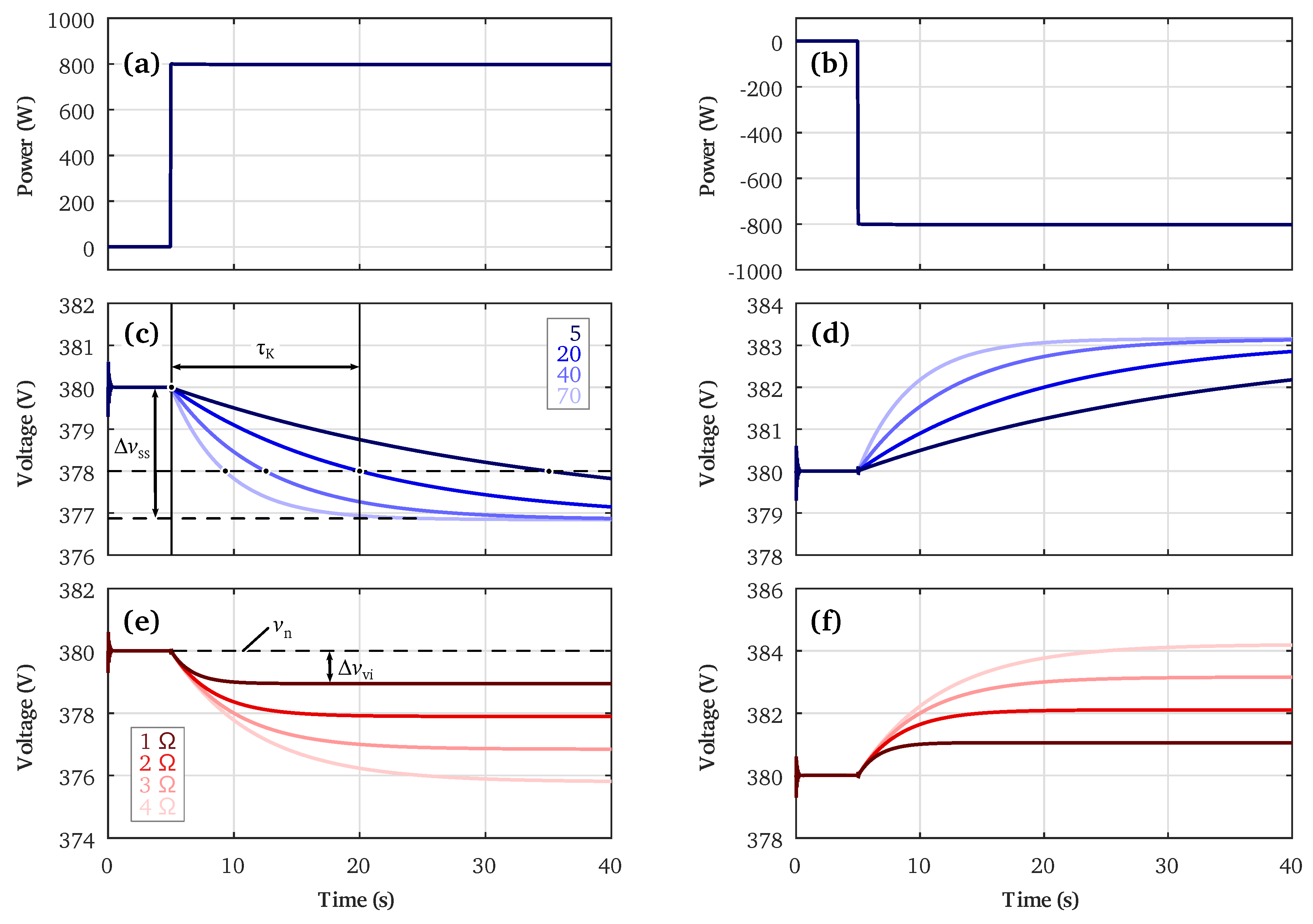
Figure 8.
Supplied and load power with the proposed control configured for different dynamic systems.
Figure 8.
Supplied and load power with the proposed control configured for different dynamic systems.

| Parameter | Symbol | Value |
|---|---|---|
| Rated grid voltage | 230 V | |
| Rated grid frequency | 50 Hz | |
| Filter inductance | , | 0.5 mH |
| Filter resistor | , | 10 mΩ |
| Filter capacitance | , | 50 μF |
| Load power | ±800 W | |
| Damping factor | 0.05 |
| J | τJ |
|---|---|
| 2 kg·m2 | 1.97 s |
| 6 kg·m2 | 2.93 s |
| 20 kg·m2 | 9.75 s |
| 40 kg·m2 | 19.54 s |
| m | |Δfdr| |
|---|---|
| 0.12 Hz/kW | 0.049 Hz |
| 0.17 Hz/kW | 0.066 Hz |
| 0.22 Hz/kW | 0.087 Hz |
| 0.3 Hz/kW | 0.13 Hz |
| Parameter | Symbol | Value |
|---|---|---|
| Rated grid voltage | 380 V | |
| Filter inductance | , | 0.5 mH |
| Filter resistor | , | 10 mΩ |
| Filter capacitance | , | 0.5 mF |
| Load power | ±800 W | |
| LPF time constant | 0.05 |
| KLPF | τK |
|---|---|
| 5 | 4.36 s |
| 20 | 7.63 s |
| 40 | 15.26 s |
| 70 | 30.5 s |
| ZV | |Δvvi| |
|---|---|
| 1 Ω | 1.05 V |
| 2 Ω | 2.1 V |
| 3 Ω | 3.16 V |
| 4 Ω | 4.19 V |
© 2017 by the authors; licensee MDPI, Basel, Switzerland. This article is an open access article distributed under the terms and conditions of the Creative Commons Attribution (CC-BY) license (http://creativecommons.org/licenses/by/4.0/).
Share and Cite
MDPI and ACS Style
Unamuno, E.; Barrena, J.A. Equivalence of Primary Control Strategies for AC and DC Microgrids. Energies 2017, 10, 91. https://doi.org/10.3390/en10010091
AMA Style
Unamuno E, Barrena JA. Equivalence of Primary Control Strategies for AC and DC Microgrids. Energies. 2017; 10(1):91. https://doi.org/10.3390/en10010091
Chicago/Turabian StyleUnamuno, Eneko, and Jon Andoni Barrena. 2017. "Equivalence of Primary Control Strategies for AC and DC Microgrids" Energies 10, no. 1: 91. https://doi.org/10.3390/en10010091
Note that from the first issue of 2016, this journal uses article numbers instead of page numbers. See further details here.