An Improved Commutation Prediction Algorithm to Mitigate Commutation Failure in High Voltage Direct Current
by
Xinnian Li
1,*, 
Fengqi Li
2,
Shuyong Chen
3,
Yanan Li
4,
Qiang Zou
5,
Ziping Wu
6 and
Shaobo Lin
3 1
School of Electrical Engineering, Beijing Jiaotong University, Beijing 100044, China
2
State Grid Operation Company, Beijing 100052, China
3
State Key Laboratory of Power Grid Safety and Energy Conservation (China Electric Power Research Institute), Beijing 100192, China
4
State Power Economic Research Institute, Beijing 102209, China
5
NR Electric Co., Ltd., Nanjing 211102, China
6
Information Trust Institute, University of Illinois at Urbana-Champaign, Champaign, IL 61801, USA
*
Author to whom correspondence should be addressed.
Energies 2017, 10(10), 1481; https://doi.org/10.3390/en10101481
Submission received: 20 July 2017
/
Revised: 12 September 2017
/
Accepted: 18 September 2017
/
Published: 25 September 2017
(This article belongs to the Special Issue Emerging Power Electronics Technologies for Power Systems and Machine Drives)
Abstract
:Commutation failure is a common fault for line-commutated converters in the inverter. To reduce the possibility of commutation failure, many prediction algorithms based on alternating current (AC) voltage detection have already been implemented in high voltage direct current (HVDC) control and protection systems. Nevertheless, there are currently no effective methods to prevent commutation failure due to transformer excitation surge current. In this paper, an improved commutation failure prediction algorithm based on the harmonic characteristics of the converter bus voltage during transformer charging is proposed. Meanwhile, a sliding-window iterative algorithm of discrete Fourier transformation (DFT) is developed for detecting the voltage harmonic in real time. This method is proved to be an effective solution, which prevents commutation failure in cases of excitation surge current, through experimental analysis. This method is already implemented into TianShan-ZhongZhou (TianZhong) ± 800 kV ultra high voltage direct current (UHVDC) system.
1. Introduction
High voltage direct current (HVDC) is widely used for bulk power transmission with lower energy loss and flexible control ability [1,2,3,4,5,6]. Thus, in the last decade, more than 20 HVDC projects have been completed in China. It is inevitable for line commutate converter (LCC) thyristor valves to experience a commutation failure when a fault occurs around the inverter AC network, especially under conditions in which the inverter AC bus is 10% to 15% below the rated voltage [7].
Efforts have been made to study the reasons for commutation failure and the methods to mitigate such an issue [8,9]. Many methods regarding the prediction and prevention of commutation failures were presented in most of the literature [10,11,12,13,14,15,16,17,18,19,20], such as power component fault detection, direct-current predictive control, commutation area detection, and so on. A more detailed description of the commutation prediction method, which has been successfully used in HVDC projects, was proposed [21,22]. In general, the above commutation prediction methods can effectively detect voltage sags due to AC side ground fault and prevent the potential commutation failure or even continuous commutation failure via increasing the extinction angle proportionally to the voltage sag.
However, the above methods are difficult to perform correctly when the converter bus voltage is affected by harmonics such as the transformer excitation surge current. TuanLin-FengJing ± 500 kV HVDC was tripped by commutation failure protection in 2013, when LianTang, a ultra high voltage alternating current UHVAC station nearby, was energizing its transformer [23]. GaoLing back-to-back HVDC went through four continuous commutation failures on 21 August 2015, when SuiZhong, an adjacent power plant, was energizing its boost transformer. The active power through TianShan-ZhongZhou (TianZhong) ± 800 kV UHVDC fluctuated between 3660 MW and 4040 MW for 13 s after GuanDu, a substation nearby, energized its transformer on 21 March 2016.
The excitation surge current produced by energizing a large transformer could be damaging to the grid. Since an excitation surge current can be sustained for longer than 10 s and can be magnified after traveling along the power transmission line [24], it could be the most reasonable practical explanation for the continuous commutation failure of HVDC.
Following the analysis of the response of the commutation failure prediction method applied to the TianZhong ± 800 kV UHVDC project on 21 March 2016, an improved commutation prediction method based on the harmonic characteristics of the converter bus voltage is proposed in this paper. This method is tested using an real-time digital simulator (RTDS) simulation platform, and the experimental results demonstrate its effectiveness. Moreover, this method is already implemented in the TianZhong ± 800 kV UHVDC system and will be applied to other HVDCs in the near future; it is especially suitable for those HVDCs that feed power into the same nearby grid.
2. Commutation Failure
For a three-pulse thyristor bridge, during the commutation of the direct current from one valve to another, if the conducting valve cannot recover interdiction capability from the reverse voltage, the valve will continue to conduct while the succeeding valve fails to do so. This phenomenon is called commutation failure.
Influencing Factors of Commutation Failure
The following equation can be obtained from:
Equation (1) reveals the main impact factors of the converter commutation, which is characterized by the extinction angle (γ), including the commutating reactance Xr, direct current (DC) steady-state current at the inverter side Id, the amplitude of commutation voltage E2m, and the trigger advance angle β.
The partial derivatives of the variables on the right side of the Formula (1) can be obtained:
On the inverter side, the firing angle is greater than π/2 radians. The overlap angle varies roughly with DC current, which changes approximately inversely with the DC voltage on the inverter side. Equation (2) shows that commutation failures in HVDC systems are mainly caused by voltage magnitude reduction, DC current increment, triggering advance angle decrement, and commutation reactance increment.
There are two methods to prevent commutation failure:
- (1)
- Increasing the γ angle in normal conditions, which will consume much more reactive power.
- (2)
- When a commutation failure is detected in an HVDC system, the inverter decreases the α angle in order to increase the commutation margin and avoid commutation failure.
3. Analysis of the Response of the Commutation Failure Prediction Method for TianZhong ± 800 kV Ultra High Voltage Direct Current Project
3.1. The Commutation Failure Prediction Method in an High Voltage Direct Current Project
The basic reason for commutation failure is a lack of commutation margin and results over a short extinguishing time. If a high level γ angle is maintained, this will cost much more in terms of reactive power. In the TianZhong ± 800 kV UHVDC control system, there is a model for commutation failure prediction (CFPREV), which can solve this antinomy preferably, as shown in Figure 1. This method includes two parallel parts: one is based on a zero-sequence component for unsymmetrical faults such as single-phase earth faults, and the other one is based on an abc-αβ transformation to detect three-phase symmetrical faults.
If an AC system has a single-line ground fault, the converter bus voltage will contain a zero-sequence component, Z, which is obtained by adding up the three-phase instantaneous voltage, as shown in Equation (3):
As shown in Figure 2, if the zero sequence component of the converter bus voltage is greater than a preset value, the commutation prediction logic will switch from a normal control strategy to another strategy in the next 20 ms by immediately decreasing the firing angle for a certain degree, which is proportional to the maximal zero sequence component, and will maintain it for a certain time (12 ms in this case). Once the AC fault has been cleared, i.e., when the zero sequence component of the converter bus voltage is lower than its setting, the prediction logic will increase the firing angle order slowly with a time constant of 30 ms, enabling the commutation prediction logic to return to the normal control strategy smoothly.
Another part is based on abc-αβ transformation to detect three-phase faults. abc-αβ transformation uses the rotating vector to express three phase voltages:
In the above formula, uα and uβ correspond to the projection of the vector on to the α-axis and the β-axis in the αβ-plane. By transformation, we can obtain a rotating vector, ω, which rotates in the αβ-plane at a fixed speed. The magnitude of rotating vector αβ_SUM can be calculated using the formula below:
When a fault occurs in the AC system, αβ_SUM is compared to a filtered αβ_SUM, with a relatively large time constant as the pre-fault voltage. If the difference between the two values is greater than the pre-defined level, the CFPREV model will kick in, convert the difference to an angle value, and finally subtract the angle value from the inverter α angle, advancing the firing instant, and leaving a bigger commutation margin. In the TianZhong HVDC project, the CFPREV program is installed in digital signal processor (DSP), and the program step is 50 µs. For a 50 Hz AC system, this value is converted to the angle value of 0.9°. CFPREV can act immediately after an AC system fault occurs.
3.2. The Performance of Commutation Failure Prediction During the Disturbance
The TianZhong ± 800 kV UHVDC project was operating with four bipolar converters rated at 4000 MW on March 21, 2016 before the disturbance occurred.
The waveform during the disturbance is given in Figure 3. The output signal of the CFPREV system, α_CFPREV in the third row, was unstable. It jumped 8.4° in 1 ms, remained stable for 20 ms, and then decreased back in the next 20 ms, repeating the process every 40 ms. Since the firing angle order increased quickly and decreased slowly, the extinction angle increased quite a lot over a long period of time. Since more reactive power was consumed by the inverters, three seconds later a filter sub-bank was switched in. During this process, the transmission power changed in the range between 3660 MW and 4040 MW as a result of the extinction angle variations.
3.3. Analysis of the Converter Bus Voltage
The zero sequence component of the converter bus voltage, which repetitively changed between 60 kV at 20 ms with abundant harmonics, is shown in Figure 4. The peak value is around 60 kV. This explains the reason why the output of the commutation failure prediction also varied every 40 ms.
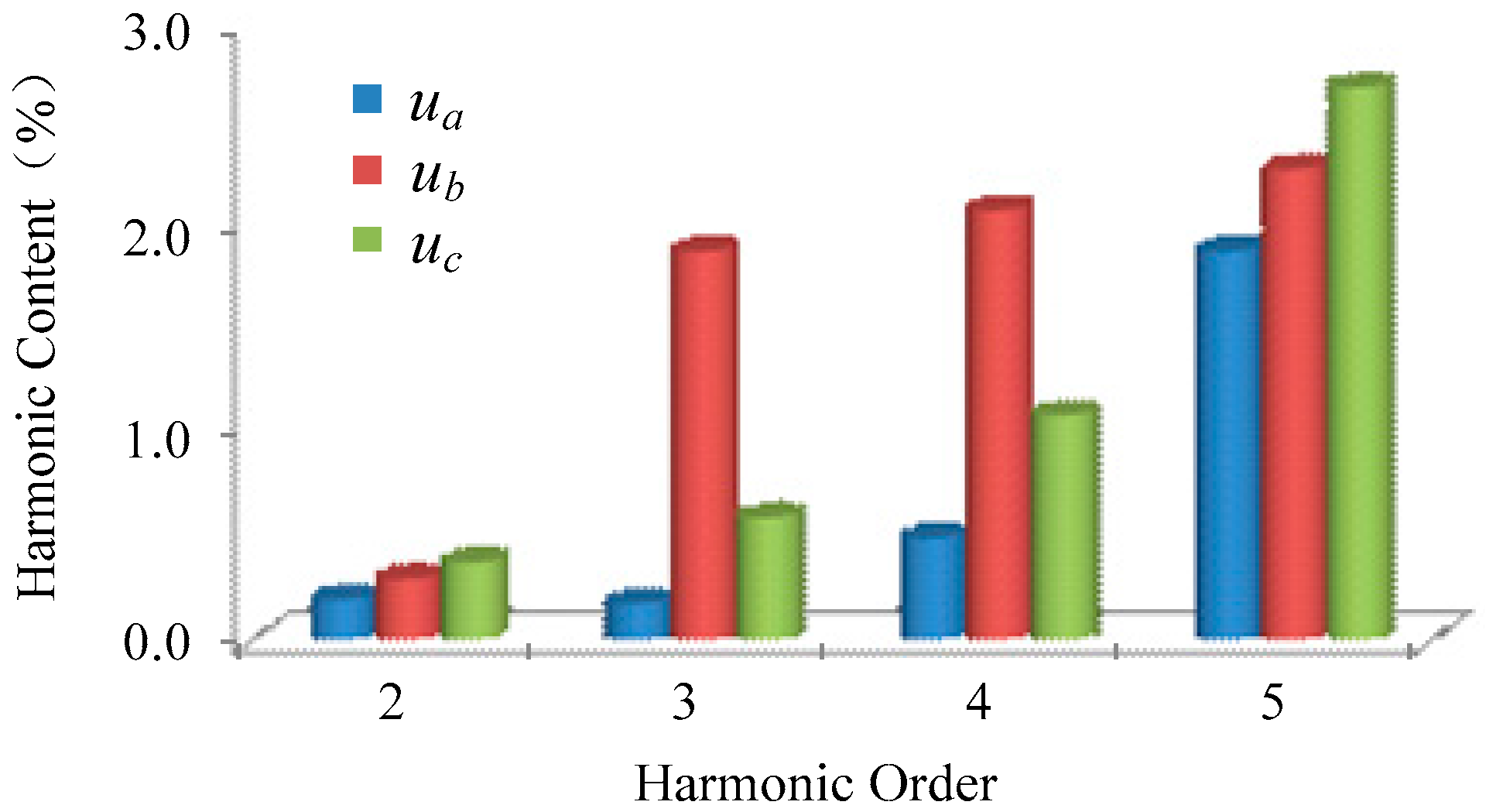
The converter bus voltage frequency analysis is conducted to understand the reason for the above zero sequence component. Figure 5 shows that abnormal third, fourth, and fifth harmonic voltages are observed in phase B, which is the key feature of transformer excitation surge current.
Further investigation demonstrates that the transformer was energized before the disturbance in the GuanDu substation, which is a 500 kV substation near the ZhongZhou converter station. The connection between the GuanDu substation and the ZhongZhou converter station is presented in Figure 6. It is easy to observe that the transformer surge current transferred from GuanDu to ZhongZhou through the AC lines connecting them.
4. A Novel Commutation Failure Prediction Method Based on the Harmonic Characteristics of the Converter Bus Voltage
According to above analysis, the present commutation failure prediction method fails to correctly handle the long term and periodically varying zero sequence component stimulated by transformer excitation current. To solve this problem, a new commutation prediction method based on the harmonic characteristics of the converter bus voltage during transformer charging is developed as follows.
4.1. Harmonic Detection Based on the Sliding-Window Iterative Algorithm of Discrete Fourier Transformation (DFT)
For any periodic signal x(τ) with a finite bandwidth, if its period is T, the bandwidth is the fundamental angular frequency ω to Nmax·ω, and the DFT [25] is expressed as follows:
where k = 0, 1, 2, …, (N − 1), τ = T/N, and N is the periodic sampling frequency.
It can be seen that the N sampling data for a complete sampling period, which is defined by the fixed starting point (i = 0), is simultaneously involved in these formulas, so the amount of calculation is huge. Obviously, these formulae are not suitable for the fast detection of instantaneous harmonic voltage.
According to the real-time requirement of harmonic voltage detection, Formulas (8) and (9) are improved as follows:
where Ncur represents the latest sampled data points and x(iτ) represents the sampling data before i sampling period. By comparing these equations with the previous two, in the improved equation for An, Bn, (i = Ncur) replaced (i = 0) and (Ncur − N + 1) replaced (N − 1); that is, the latest real-time sampling data is used for the calculation of harmonic voltage, while the oldest sampling data are eliminated accordingly.
At the same time, the second harmonic component can be calculated by the following formula:
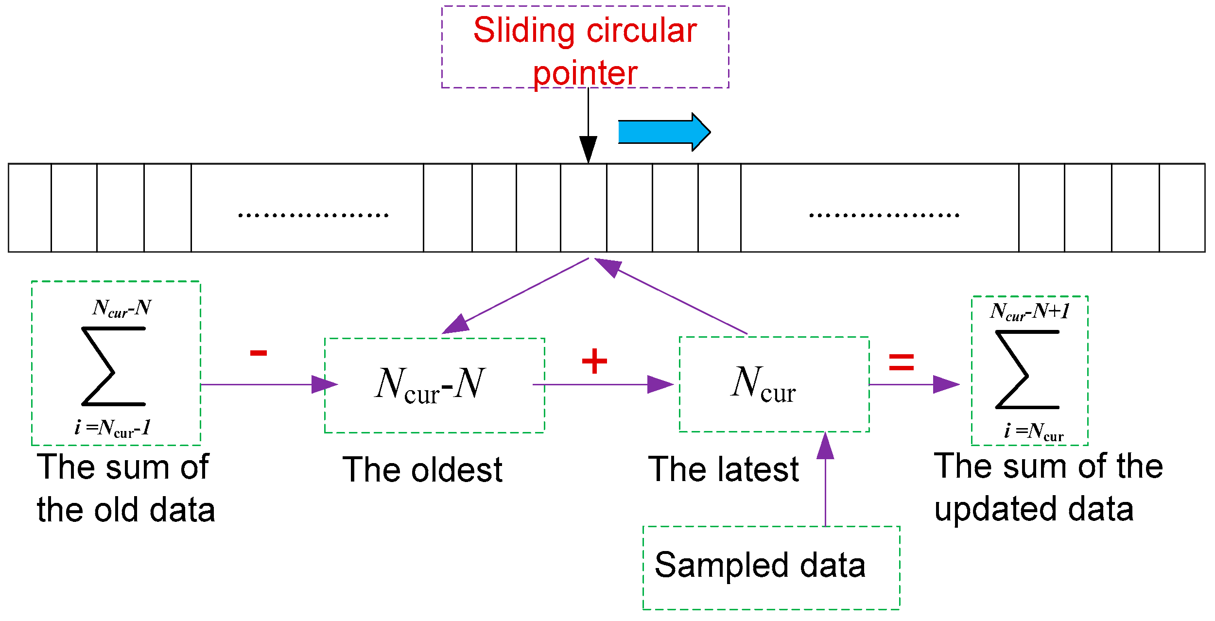
A2 and B2 must be calculated simultaneously through Formulas (13) and (14) during one sampling interval in order to obtain the desired second harmonic voltage in real time. The amount of computation is great when the sampling frequency of the system is high (i.e., N is relatively large). For this reason, a new computational model is developed to simplify the calculation process of the sliding-window iterative algorithm. It is shown in Figure 8.
According to the calculation model in Figure 8, N point sampled data in the power frequency period is stored in the continuous data space after being multiplied with the appropriate rotation factors. The present sampled data storage location is determined by the loop pointer. After completing a full period of N points sampled data calculation, the pointer should point back to the starting position of the storage space so as to start the next cycle of replacement data simultaneously. Therefore, Equations (15) and (16) can be simplified as the calculation of Formulas (13) and (14):
The sum operation of Formulas (13) and (14) is reduced to a subtraction and an addition by means of the above transformation; the new data sum is restored to the unit of the old data sum storage after the computation. Therefore, the whole process of the iterative calculation of the sliding window can be completed in the power frequency cycle at the initialization stage. The summation operation can be completed absolutely one sampling period later. In this way, the operation duration of harmonic voltage detection will be significantly reduced by using the iterative sliding window algorithm, and the real-time performance of such a system is also improved greatly.
The sliding window iterative algorithm is much simpler and faster than fast Fourier transformation (FFT) when the single harmonic voltage is calculated. It is very important for the frequency dividing control when designing a relevant controller.
4.2. A New Commutation Failure Prediction Method
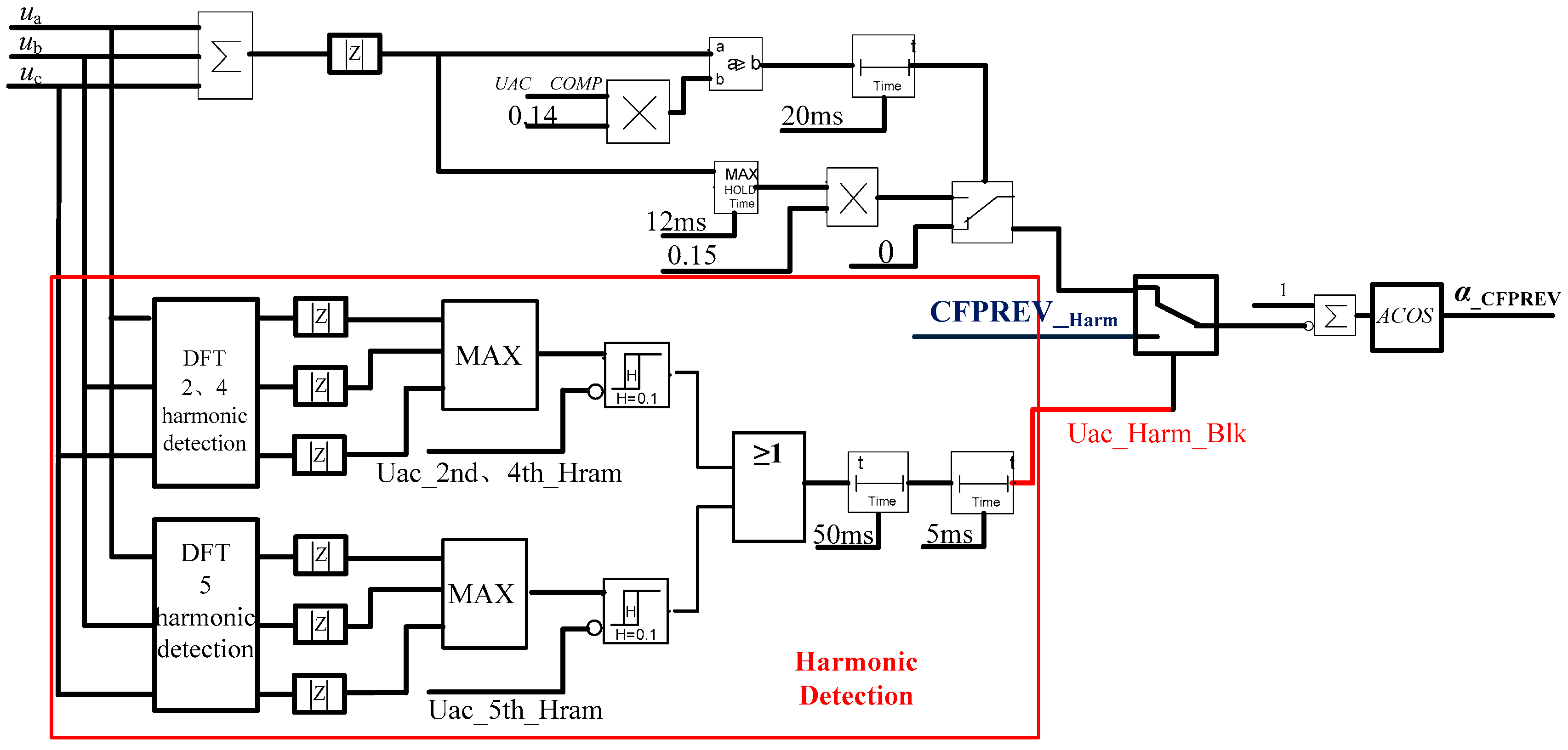
Through comparison with the present CFPREV logic used in the TianZhong ± 800 kV UHVDC project, which is shown in Figure 2, an improved commutation failure prediction algorithm is proposed based on the harmonic characteristics of the converter bus voltage during transformer charging. The second, fourth, and fifth harmonics of the converter bus are calculated and compared with their settings. If any of them are greater than their settings, the signal (Uac_Harm_Blk) is set, and the output of the prediction logic is held as its setting value (CFPREV_Harm). The logic is shown in Figure 9.
Uharm_max = MAX(Uac_2nd_Harm, Uac_4th_Harm, Uac_5th_Harm)
5. Experiments and Results
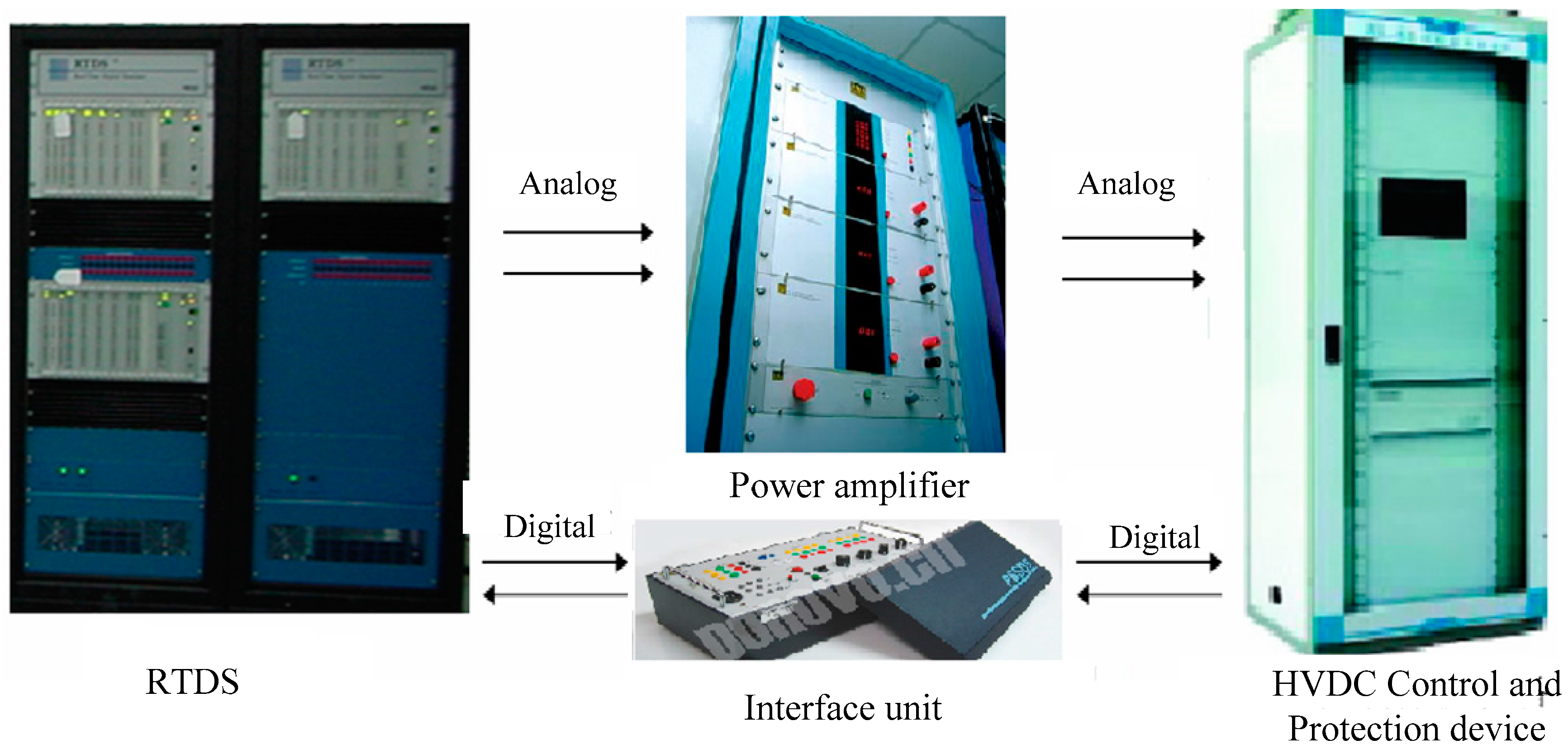
The experiment through RTDS is carried out to reproduce the above process and verify the proposed algorithm. The RTDS experimental system is shown in Figure 10. The topology of the TianZhong ± 800 kV UHVDC transmission system and the AC network of the ZhongZhou converter station nearby are modeled in detail. The model includes the main circuit with the primary equipment, consisting of converters, transformers, DC lines, DC filter, AC filter, and a control and protection system in accordance with the practical system configuration. These detailed parameters are shown in Table 1 and Table 2 and Figure 11.
5.1. To Reproduce the Process with the Traditional Commutation Failure Prediction Strategy
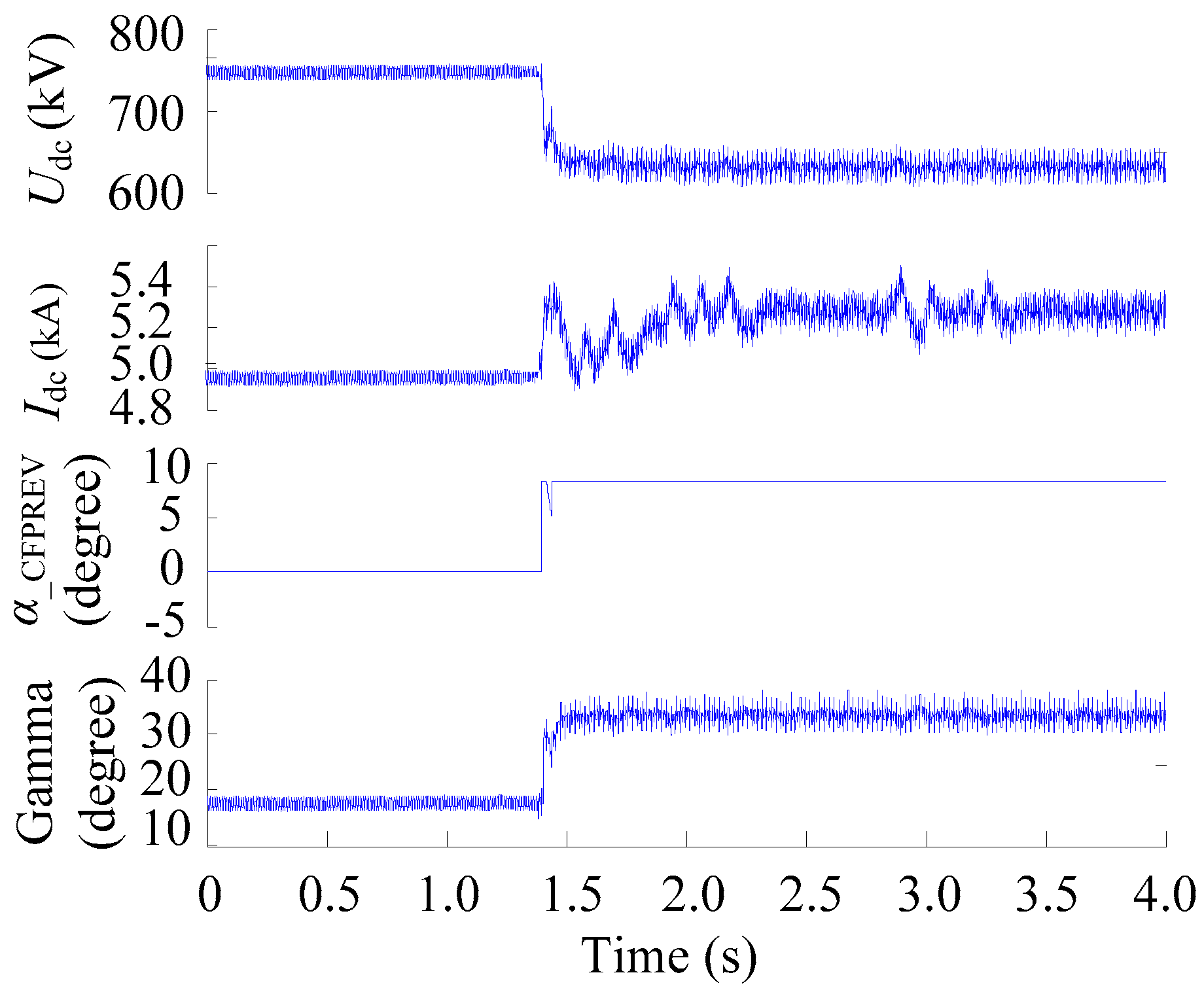
After the transformer excitation current recorded in Figure 7 is injected into the bus bar of the GuanDu substation, the same transient behavior is observed in HVDC according to Figure 12. The output of the commutation failure prediction (α_CFPREV) swings in the range between nine and 0° at a periodicity of 40 ms, resulting in a disturbance of both the DC voltage and current.
5.2. To Verify the Proposed Commutation Failure Prediction Strategy under the Same System Configuration
The proposed commutation failure prediction strategy is implemented into the control system and evaluated by injecting the same transformer excitation current into the bus bar of the GuanDu substation. The RTDS experimental results are shown in Figure 13.
The output of the commutation failure prediction changes from 0° to 9° as soon as the transformer of the GuanDu substation is energized and the zero sequence component is detected at the converter bus of the ZhongZhou converter station. It is beneficial for the inverter to prevent commutation failure due to the converter bus voltage distortion caused by the nearby excitation surge current.
5.3. To Verify the Proposed Commutation Failure Prediction Strategy Under 1000 kV Ultra High Voltage Transformer Charging
With the increase in the AC voltage level, the capacity of the 1000 kV UHV AC transformer gradually developed from 3000 MVA to 4500 MVA. When the UHV Transformer is charged, the inrush current amplitude is larger and lasts longer, and the problem of harmonic voltage distortion and voltage reduction becomes more and more serious.
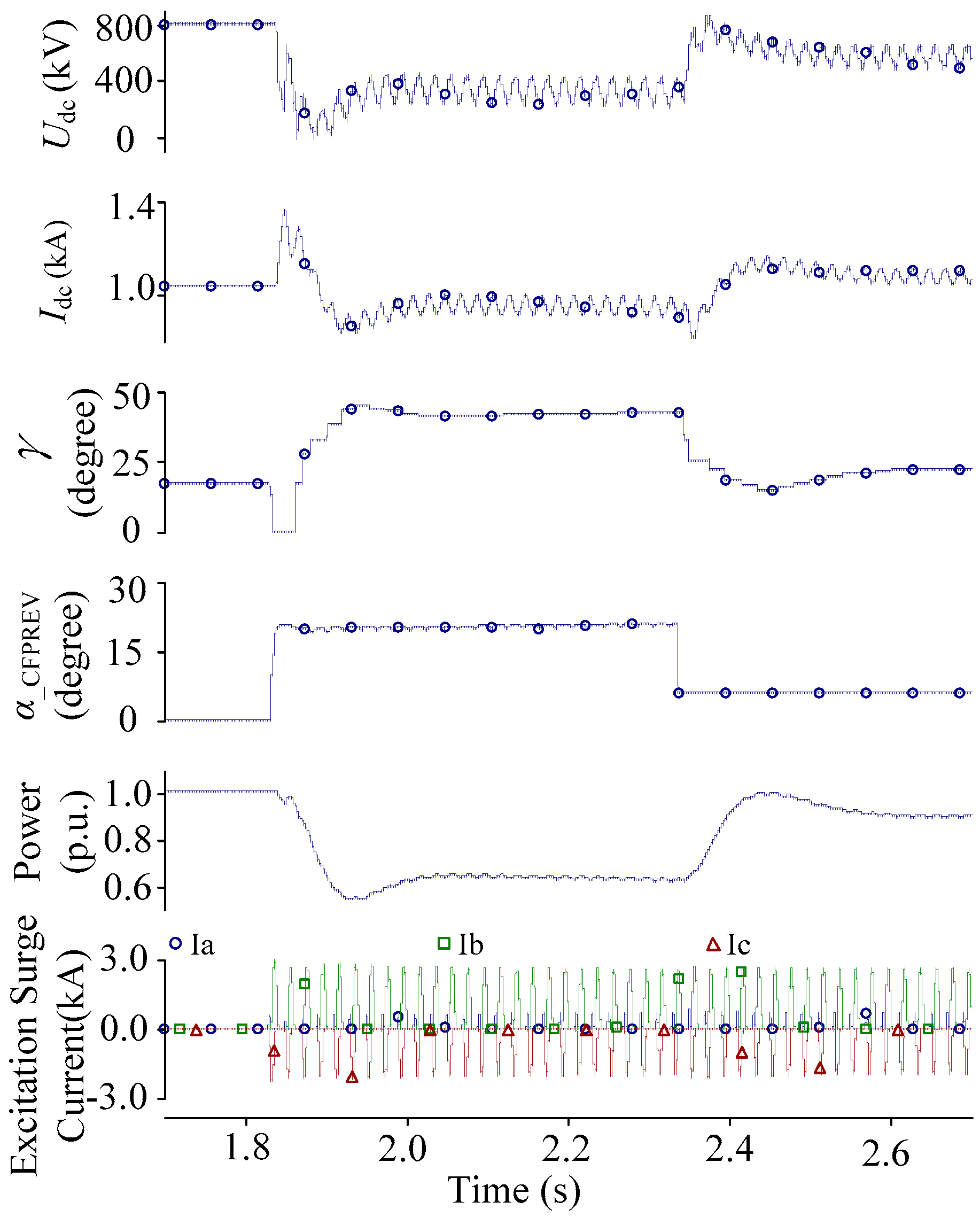
Figure 14 shows the waveforms of the charging inrush current of the 1000 kV UHV Transformer affecting the HVDC transmission system. The commutation failure of the inverter occurs at the same time, which is caused by the charging inrush current of the UHV Transformer. The CFPREV model kicks in, and the output signal of this model is 20.6°. As the inrush current attenuates slowly, the zero sequence component voltage of the original commutation failure prediction is greater than the set value for a long time, and the extinction angle is maintained near 41°. The DC voltage drops to 561 kV, which leads to the voltage dependent current order limiter (VDCOL) acting (as shown in Figure 15), and the DC current is limited at 0.88 p.u. (DC power is 0.64 p.u.). In 2.4 s, the CFPREV model based on the harmonic detection function is put into operation, and the output signal of this model drops to 6°. The extinction angle is maintained near 22°; the DC voltage rises to 694 kV, which is less than the action value of VDCOL; and the DC current goes up to 1.06 p.u. (DC power is 0.93 p.u.). Therefore, our model can not only prevent continuous commutation failure from transformer excitation surge current but also can mitigate the sharp decrease of DC power.
5.4. To Verify the Proposed Commutation Failure Prediction Strategy in TuanLin-FengJing ± 500 kV High Voltage Direct Current
TuanLin-FengJing (LinFeng) ± 500 kV HVDC was tripped by commutation failure protection in 2013, when LianTang, a UHVAC station nearby, was energizing its transformer [23]. In reference [23], the LinFeng HVDC model was established by using a detailed model consistent with the practical project. Through simulation studies, we put forward the measures to optimize the pole control system such as (1) to cancel the instantaneous current compensation function in the pole control system and (2) to optimize the functions of VDCOL and DC controller commutation failure prediction.
In order to verify the proposed commutation failure prediction strategy in LinFeng HVDC, the LinFeng HVDC model was established in RTDS, and an improved commutation failure prediction algorithm based on the harmonic characteristics of the converter bus voltage is applied. In order to analyze a cyclical commutation failure problem, the practical magnetizing surge current of LianTang first needs to be calculated by the simulation (the initial value is 4699 A). Next, the same magnetizing surge current is injected into the AC system at the inverter side of LinFeng so as to study the commutation failure of LinFeng HVDC under the magnetizing surge current distortion and propose a solution for periodic commutation failure accordingly. Figure 16 is the waveform before the optimization of the commutation failure prediction. Five periodic commutation failures happen at the inverter, which behaves in the same way as in [23].
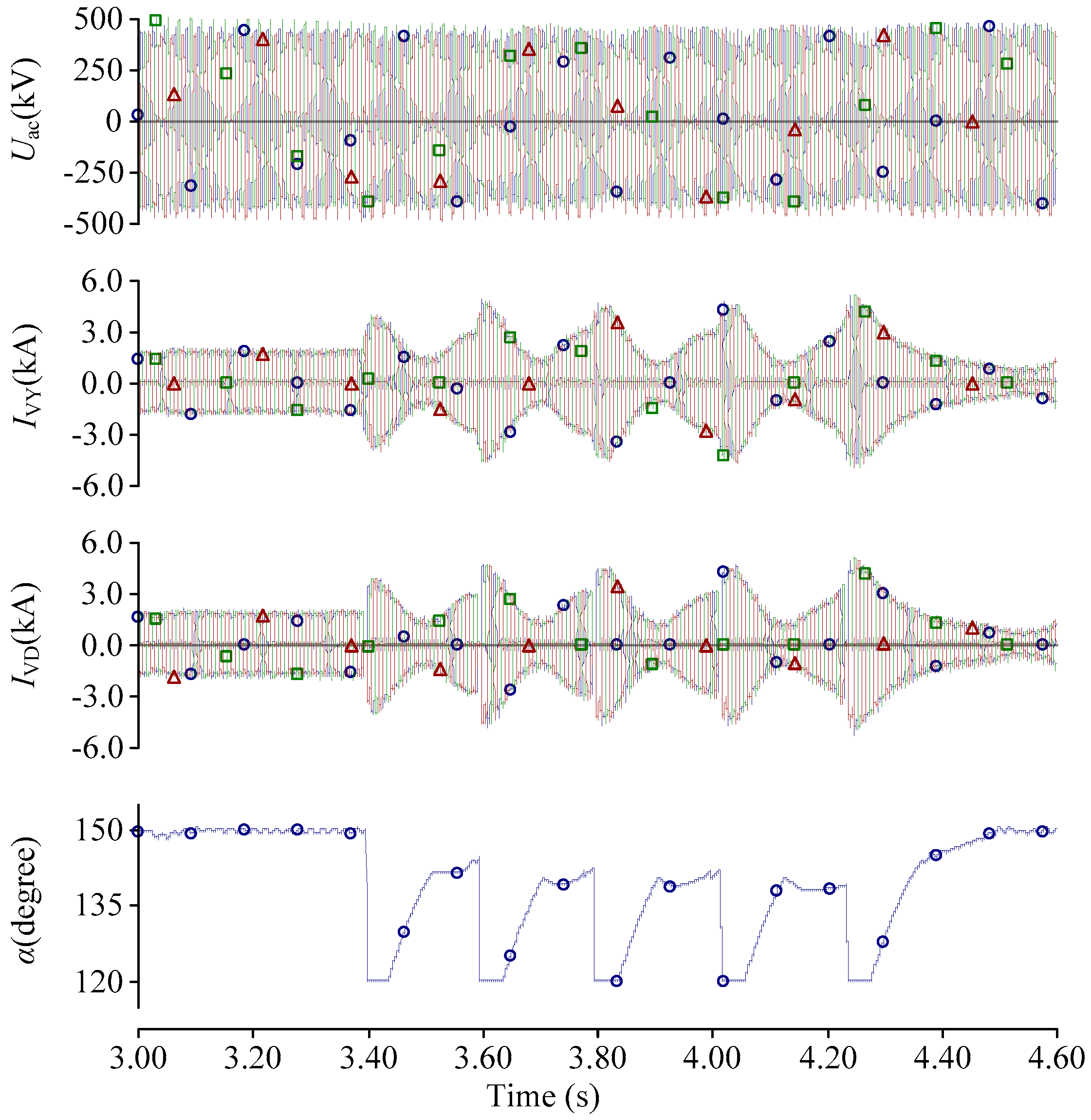
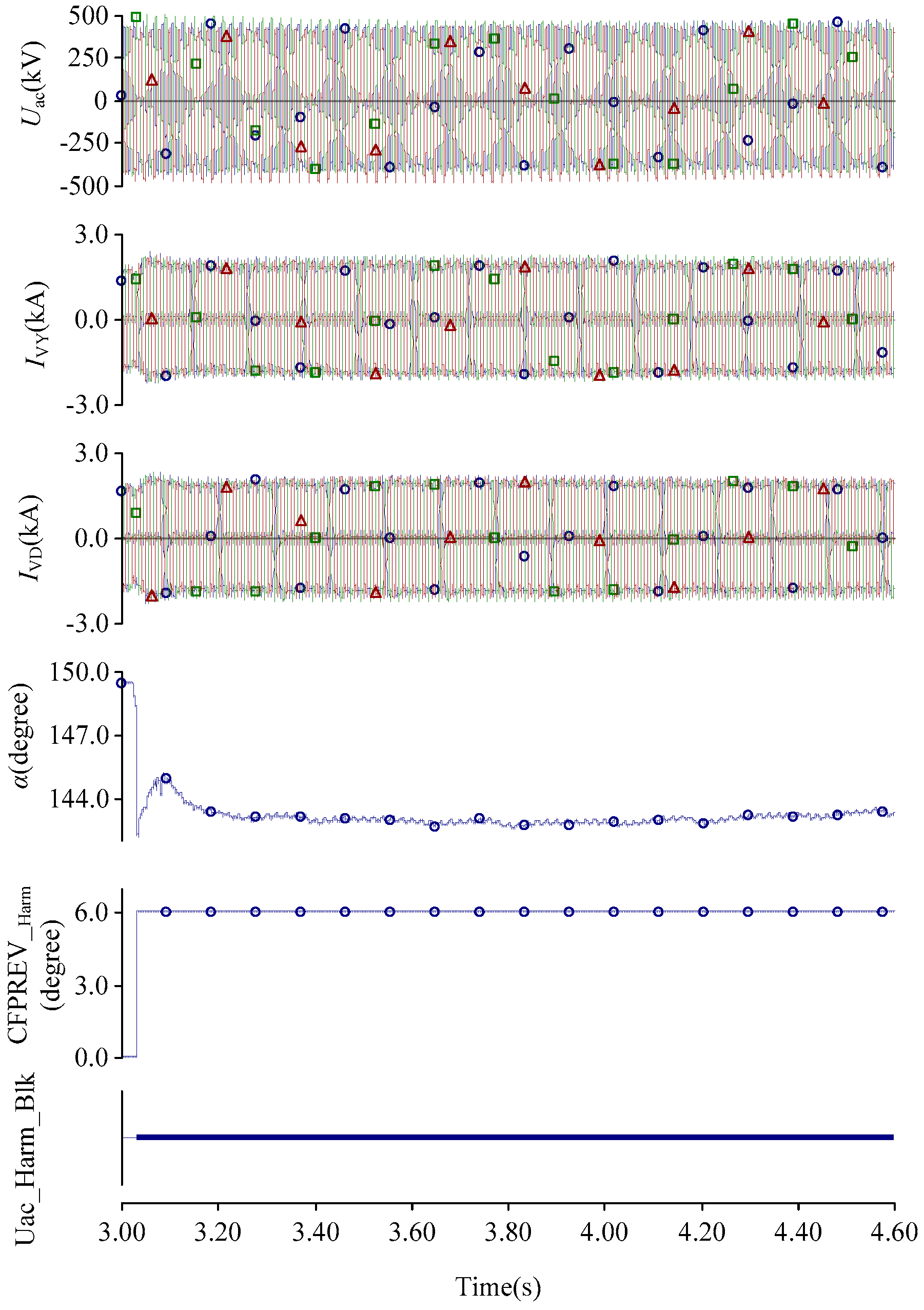
Figure 17 is a test waveform applied to an improved commutation failure prediction algorithm. In the third second, the second, fourth, and fifth harmonic voltage of the converter bus are greater than their settings, and the output signal of this model (CFPREV_Harm) increases to 6°. The firing angle is maintained near 144°, and the extinction angle rises up to 23°, which increase the commutation margin. Therefore, it can prevent the continuous commutation failure caused by transformer excitation surge current. The method proposed in this paper is more straightforward and effective in cases in which commutation failure is caused by inrush current.
6. Conclusions
The traditional prediction algorithm of commutation failure will be inappropriate when the long-term voltage distortion of a converter bus is caused by the energizing transformer near the inverter station, and the distortion consequently leads to continuous commutation failures. This is potentially dangerous to AC/DC systems.
In this paper, an improved commutation failure prediction algorithm is proposed based on the harmonic characteristics of the converter bus voltage during transformer charging. Meanwhile, a sliding-window iterative algorithm of discrete Fourier transformation (DFT) is developed for detecting the harmonic voltage, which is simpler and faster than FFT when the single harmonic voltage is calculated. If the harmonic voltage is greater than the settings, the correct additional minimal extinction angle is held until the excitation current decreases to an acceptable level. Therefore, it can not only prevent continuous commutation failure due to transformer excitation surge current but can also mitigate the sharp decrease of DC power. This method has been proved to be effective through RTDS experiments in the LinFeng and TianZhong HVDC systems. Moreover, it is already implemented in the TianZhong ± 800 kV UHVDC system.
Acknowledgments
The research is supported by “science and technology project of the State Grid Corporation of China (FX71-16-003) and (XT71-15-045)”.
Author Contributions
Xinnian Li, Fengqi Li, Yanan Li, and Shuyong Chen proposed the core idea and developed the models. Qiang Zou performed the experiments, exported the results, and analyzed the data. Ziping Wu and Shaobo Lin revised the paper. Xinnian Li and Fengqi Li contributed to the design of the models and the writing of this manuscript.
Conflicts of Interest
The authors declare no conflicts of interest.
Abbreviation
The following abbreviations are used in this manuscript:
| γ | Extinction Angle |
| α | Firing Angle |
| Xr | Commutating Reactance |
| Id | Dc Current |
| E2m | Commutation Voltage |
| β | Trigger Advance Angle |
| IVY | YY Transformer Current in Valve Side |
| IVD | YD Transformer Current in Valve Side |
| CFPREV | Commutation Failure Prediction |
| α_CFPREV | The Output of CFPREV |
| u0 | Zero Sequence Component |
| uα | uαβ in α axis |
| uβ | uαβ in β axis |
| uαβ | The Magnitude of Rotating Vector |
| ua, ub, uc | Three-phase Instantaneous Voltage of Converter Bus |
| Uac_COMP | Magnitude of Uac Before Fault |
| Ncur | The Latest Sampled Data Points |
| x(iτ) | Sampling Data Before i Sampling Period |
| TianZhong | TianShan-ZhongZhou |
| UHVDC | Ultra High Voltage Direct Current |
| DFT | Discrete Fourier Transform |
| FFT | Fast Fourier Transformation |
| CFPREV_Harm | The output of CFPREV based on harmonic detection |
| Uac_Harm_Blk | Action signal of CFPREV based on harmonic detection |
| RTDS | Real-time Digital Simulator |
| HP | High-pass Filter |
| BP | Band-pass Filter |
| SC | Shunt Capacitor |
References
- Bidadfar, A.; Nee, H.-P.; Zhang, L.; Harnefors, L.; Namayantavana, S.; Abedi, M.; Karrari, M.; Gharehpetian, G.B. Power System Stability Analysis Using Feedback Control System Modeling Including HVDC Transmission Links. IEEE Trans. Power Deliv. 2016, 31, 116–124. [Google Scholar] [CrossRef]
- Pirooz Azad, S.; Iravani, R.; Tate, J.E. Dynamic Stability Enhancement of a DC-Segmented AC Power System via HVDC Operating-Point Adjustment. IEEE Trans. Power Deliv. 2015, 30, 657–665. [Google Scholar] [CrossRef]
- Zhang, X.; Lu, C.; Xie, X.; Dong, Z.Y. Stability Analysis and Controller Design of a Wide-Area Time-Delay System Based on the Expectation Model Method. IEEE Trans. Smart Grid 2016, 7, 520–529. [Google Scholar] [CrossRef]
- He, J.; Tang, Y.; Zhang, J.; Guo, Q.; Yi, J.; Bu, G. Fast Calculation of Power Oscillation Peak Value on AC Tie-Line After HVDC Commutation Failure. IEEE Trans. Power Syst. 2015, 30, 2194–2195. [Google Scholar] [CrossRef]
- Zhang, J.; Wu, Z.; Hu, T.; Zhang, W. Research on Coordinated Control Technology for AC/DC hybrid system in China. In Proceedings of the IEEE PES Transmission and Distribution Conference and Exposition, Chicago, IL, USA, 14–17 April 2014; pp. 1–5. [Google Scholar]
- Li, M. Characteristic Analysis and Operational Control of Large-Scale Hybrid UHV AC/DC Power Grids. Power Syst. Technol. 2016, 40, 985–991. [Google Scholar]
- Thio, C.V.; Davies, J.B.; Kent, K.L. Commutation failures in HVDC transmission systems. IEEE Trans. Power Deliv. 1996, 11, 946–957. [Google Scholar] [CrossRef]
- Wang, J.; Liang, Z.; Jiang, M.; Hu, C.; Ge, R. Case Analysis and Simulation of Commutation failure in Multi-infeed HVDC Transmission Systems. Autom. Electr. Power Syst. 2007, 31, 97–102. (In Chinese) [Google Scholar]
- Rahimi, E.; Gole, A.; Davies, B.; Fernando, I.; Kent, K. Commutation failure analysis in multi-infeed HVDC systems. IEEE Trans. Power Deliv. 2011, 26, 378–384. [Google Scholar] [CrossRef]
- Wei, Z.; Yuan, Y.; Lei, X.; Wang, H.; Sun, G.; Sun, Y. Direct-Current Predictive Control Strategy for Inhibiting Commutation Failure in HVDC Converter. IEEE Trans. Power Syst. 2014, 29, 2409–2417. [Google Scholar] [CrossRef]
- Guo, C.; Liu, Y.; Zhao, C.; Wei, X.; Xu, W. Power Component Fault Detection Method and Improved Current Order Limiter Control for Commutation Failure Mitigation in HVDC. IEEE Trans. Power Deliv. 2015, 30, 1585–1593. [Google Scholar] [CrossRef]
- Son, H.-I.; Kim, H.-M. An Algorithm for Effective Mitigation of Commutation Failure in High-Voltage Direct-Current Systems. IEEE Trans. Power Deliv. 2016, 31, 1437–1446. [Google Scholar] [CrossRef]
- Xue, Y.; Zhang, X.-P.; Yang, C. Elimination of Commutation Failures of LCC HVDC System with Controllable Capacitors. IEEE Trans. Power Syst. 2016, 31, 3289–3299. [Google Scholar] [CrossRef]
- Li, Y.; Liu, F.; Luo, L.; Rehtanz, C.; Cao, Y. Enhancement of commutation reliability of an HVDC inverter by means of an inductive filtering method. IEEE Trans. Power Electron. 2013, 28, 4917–4929. [Google Scholar] [CrossRef]
- Guo, C.; Li, C.; Zhao, C.; Ni, X.; Zha, K.; Xu, W. An Evolutional Line-Commutated Converter Integrated With Thyristor-Based Full-Bridge Module to Mitigate the Commutation Failure. IEEE Trans. Power Deliv. 2017, 32, 967–976. [Google Scholar] [CrossRef]
- Sun, Y.Z.; Peng, L.; Ma, F.; Li, G.J.; Lv, P.F. Design a fuzzy controller to minimize the effect of HVDC commutation failure on power system. IEEE Trans. Power Syst. 2008, 23, 100–107. [Google Scholar] [CrossRef]
- Hansen, A.; Havemann, H. Decreasing the commutation failure frequency in hvdc transmission systems. IEEE Trans. Power Deliv. 2000, 15, 1022–1026. [Google Scholar] [CrossRef] [Green Version]
- Tamai, S.; Naitoh, H.; Ishiguro, F.; Sato, M.; Yamaji, K.; Honjo, N. Fast and predictive HVDC extinction angle control. IEEE Trans. Power Syst. 1977, 12, 1268–1275. [Google Scholar] [CrossRef]
- Jovcic, D.; Pahalawaththa, N.; Zavahir, M. Investigation of the use of inverter control strategy instead of synchronous condensers at inverter terminal of an HVDC system. IEEE Trans. Power Deliv. 2000, 15, 704–709. [Google Scholar] [CrossRef]
- Lin, L.; Zhang, Y.; Zhong, Q.; Liao, Z. Studies of Commutation Failures in HVDC System Based on Hypersim. In Proceedings of the 2006 International Conference on Power System Technology, Chongqing, China, 22–26 October 2006; pp. 1–7. [Google Scholar]
- Zhang, L.; Dofans, L. A novel method to mitigate commutation failures in HVDC systems. In Proceedings of the 2002 International Conference on Power System Technology, Kunming, China, 13–17 October 2002; pp. 51–56. [Google Scholar]
- Lv, P.; Li, X.; Chen, L.; Yin, Y. A new method of preventing commutation failure in HVDC based on sin-cos components detection. In Proceedings of the International Conference on Electrical Engineering, YongPyong, Korea, 9–13 July 2006; pp. 2–11. [Google Scholar]
- Li, X.; Chen, X.; Li, T.; Wang, J. Research on the periodic commutation failure by 1000 kV UHV Transformer energizing for LinFeng HVDC project. Power Syst. Technol. 2014, 38, 2671–2679. [Google Scholar]
- Tong, Y. Harmonics in excitation inrush process of large power transformer and its magnification in network. Power Syst. Technol. 1995, 19, 28–31. [Google Scholar]
- Han, Z.; Guo, S. New Method to identify inrush current based on half wave Fourier analysis. Autom. Electr. Power Syst. 2005, 29, 60–63. [Google Scholar]
Figure 1.
Structure of the TianZhong ± 800 kV ultra-high voltage direct current (HVDC) control system.
Figure 1.
Structure of the TianZhong ± 800 kV ultra-high voltage direct current (HVDC) control system.
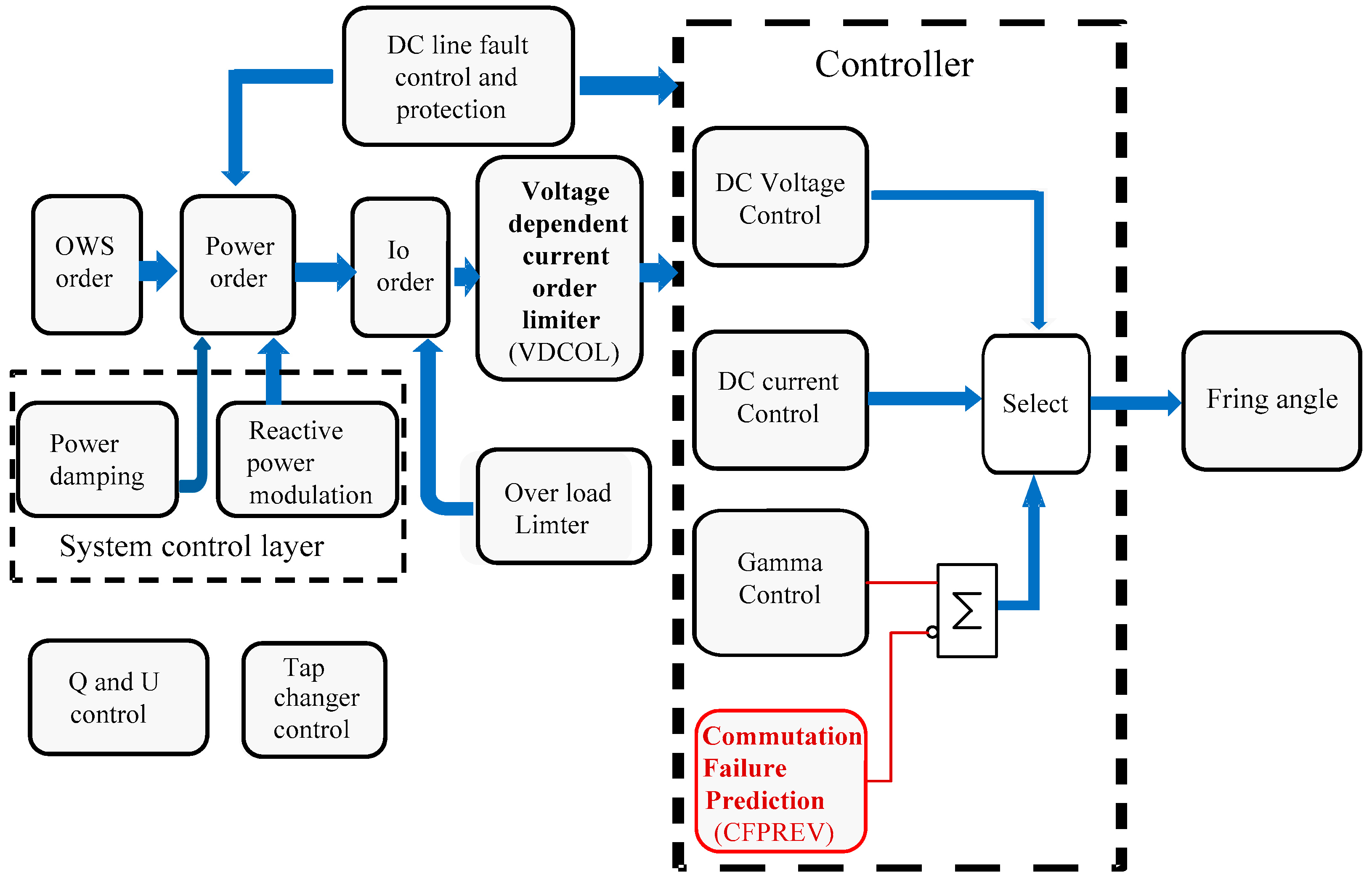
Figure 2.
A simplified logic diagram of commutation failure prediction (CFPREV).
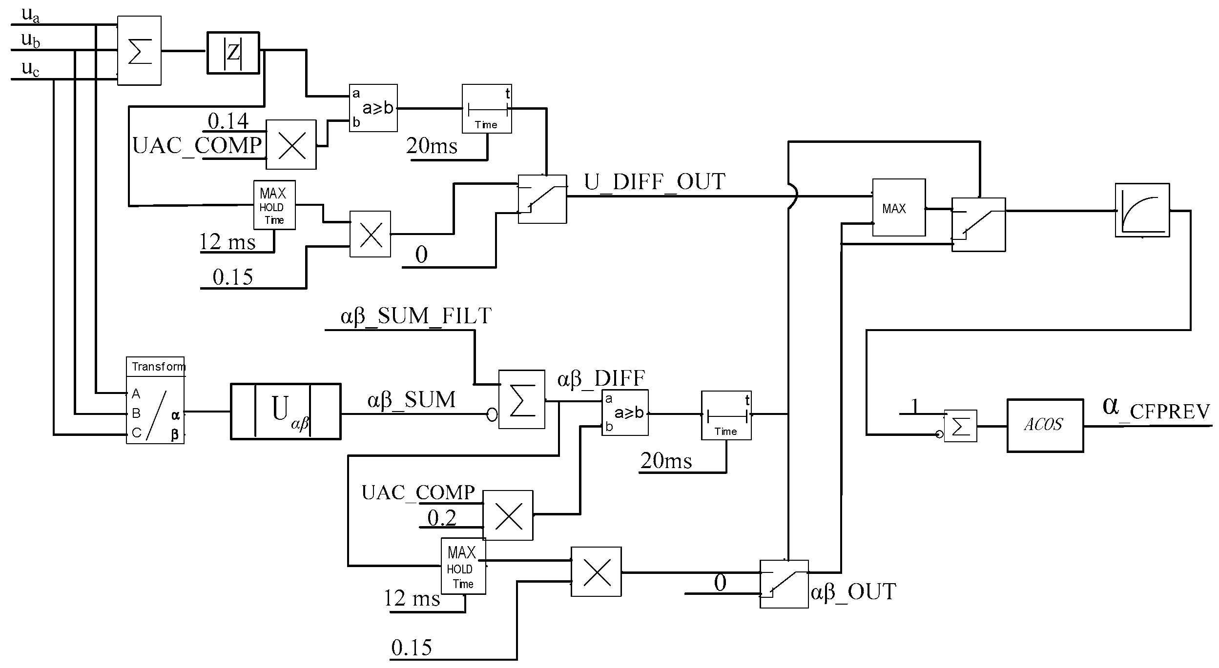
Figure 3.
The performance of the commutation failure prediction during the disturbance. (Note: Uac is the converter bus voltage in the inverter, IVY is the Yy transformer current in the valve side, α-CFPREV is the output degree of commutation failure prediction (CFPREV), and α is firing angle.)
Figure 3.
The performance of the commutation failure prediction during the disturbance. (Note: Uac is the converter bus voltage in the inverter, IVY is the Yy transformer current in the valve side, α-CFPREV is the output degree of commutation failure prediction (CFPREV), and α is firing angle.)
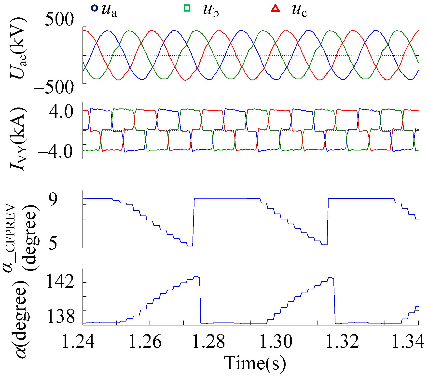
Figure 4.
Zero sequence component of the converter bus voltage.
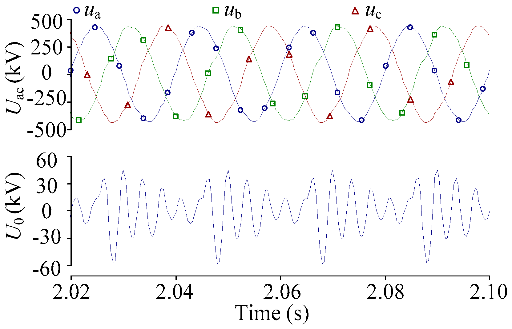
Figure 5.
Frequency analysis of the converter bus voltage.

Figure 6.
The wiring diagram of the AC/DC system.
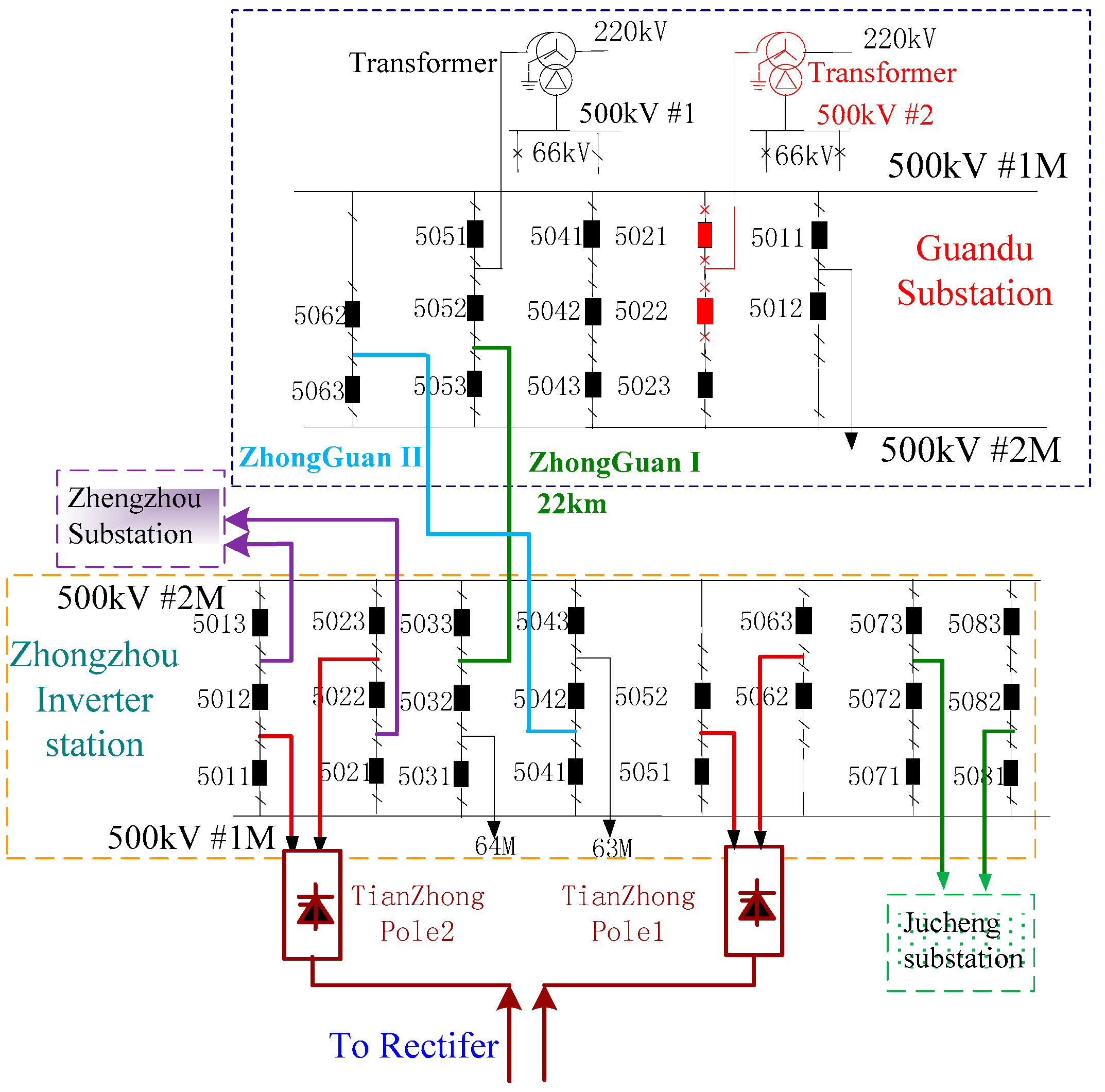
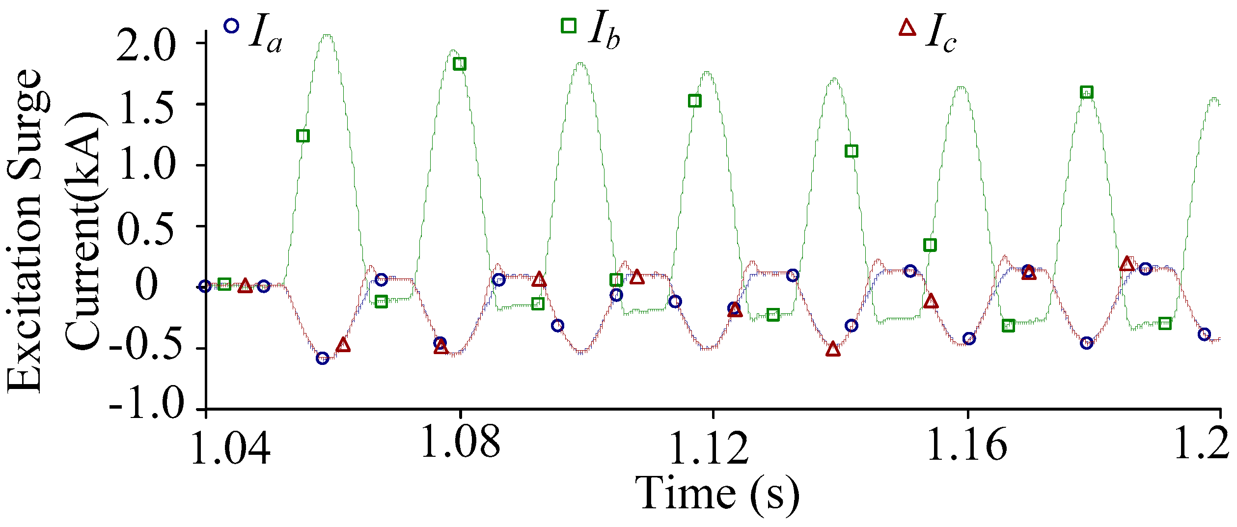
Figure 7.
The transformer excitation surge current recorded at the GuanDu substation.

Figure 8.
The sliding window iterative discrete Fourier transformation (DFT) method.

Figure 9.
A simplified logic diagram of the new commutation failure prediction method to protect against transformer excitation surge current.
Figure 9.
A simplified logic diagram of the new commutation failure prediction method to protect against transformer excitation surge current.

Figure 10.
The real-time digital simulator experimental system.

Figure 11.
A simplified diagram of the TianZhong ± 800 kV UHVDC transmission project.
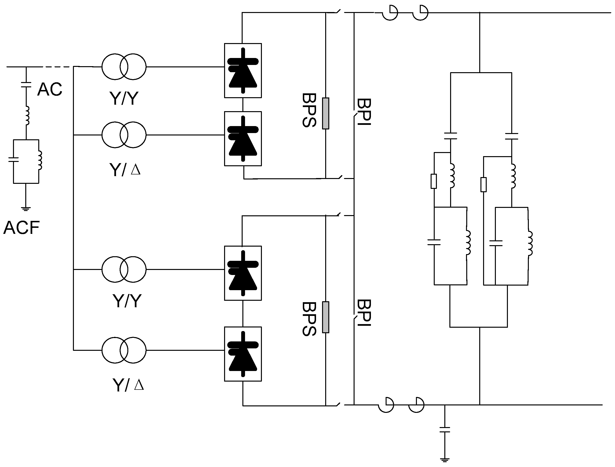
Figure 12.
Reproduction of the disturbance due to the transformer excitation current recorded at the GuanDu substation and the traditional commutation failure prediction algorithm.
Figure 12.
Reproduction of the disturbance due to the transformer excitation current recorded at the GuanDu substation and the traditional commutation failure prediction algorithm.
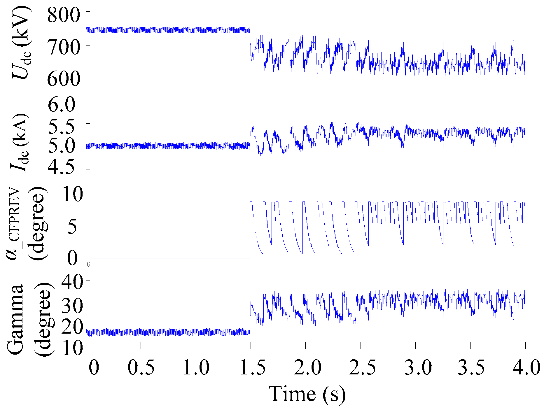
Figure 13.
Reproduction of the disturbance due to the transformer excitation current recorded at GuanDu substation and the proposed commutation failure prediction algorithm.
Figure 13.
Reproduction of the disturbance due to the transformer excitation current recorded at GuanDu substation and the proposed commutation failure prediction algorithm.

Figure 14.
Reproduction of the disturbance due to a 1000 kV UHV AC transformer excitation current and the proposed commutation failure prediction algorithm.
Figure 14.
Reproduction of the disturbance due to a 1000 kV UHV AC transformer excitation current and the proposed commutation failure prediction algorithm.

Figure 15.
The static characteristic of the voltage dependent current order limiter (VDCOL).
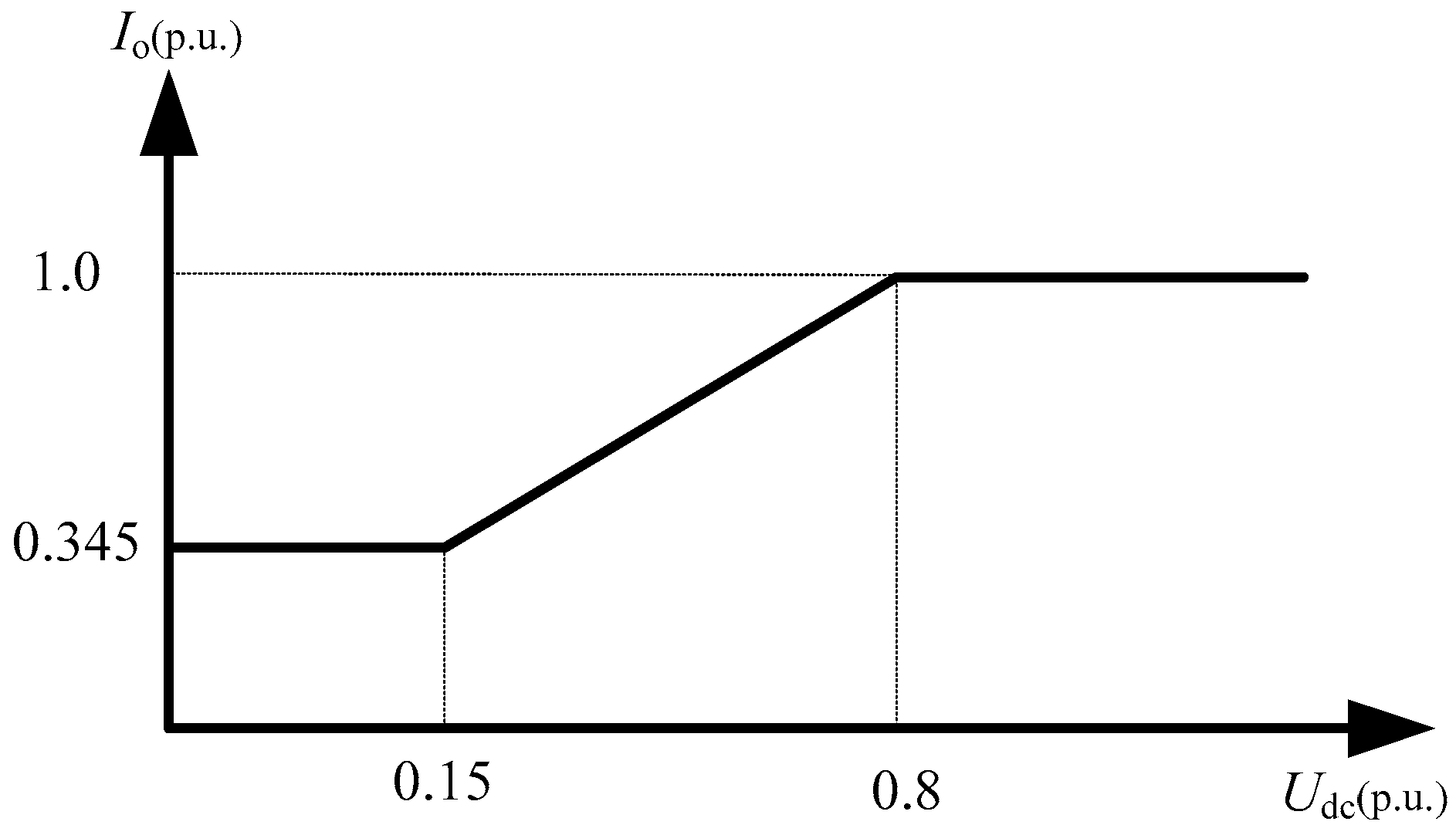
Figure 16.
The test waveform before the optimization of the commutation failure prediction.

Figure 17.
The test waveform when the improved commutation failure prediction algorithm is applied. (Note: IVD is the Yd transformer current in the valve side; CFPREV_Harm is the output of CFPREV based on harmonic detection, Uac_Harm_Blk is the action signal of CFPREV based on harmonic detection.).
Figure 17.
The test waveform when the improved commutation failure prediction algorithm is applied. (Note: IVD is the Yd transformer current in the valve side; CFPREV_Harm is the output of CFPREV based on harmonic detection, Uac_Harm_Blk is the action signal of CFPREV based on harmonic detection.).


Table 1.
The main parameters of Tianzhong ± 800 kV ultra high voltage direct current (UHVDC).
| Serial Number | Items | Units | Parameters |
|---|---|---|---|
| 1 | Bipolar rated power | MW | 8000 |
| 2 | Rated voltage | kV | 800 |
| 3 | Rated current | kA | 5.0 |
| 4 | Rated firing angle at rectifier | ° | 15 |
| 5 | Rated extinction angle at inverter | ° | 17 |
| 6 | Smoothing reactor | mH | 6 × 50 |
| 7 | the commutating reactance | % | 24 |
| 8 | The distance of DC lines | km | 2192 |
Table 2.
The AC/DC filter of TianZhong ± 800 kV UHVDC.
| Items | Location | Type |
|---|---|---|
| DC filter | TianShan | 1*HP2/39, 1*HP12/24 |
| ZhongZhou | 1*HP2/39, 1*HP12/24 | |
| AC filter | TianShan | 4*BP11BP13, 4*HP24/36, 3*HP3,5*SC |
| ZhongZhou | 8*HP12/24, 2*HP3, 9*SC |
© 2017 by the authors. Licensee MDPI, Basel, Switzerland. This article is an open access article distributed under the terms and conditions of the Creative Commons Attribution (CC BY) license (http://creativecommons.org/licenses/by/4.0/).
Share and Cite
MDPI and ACS Style
Li, X.; Li, F.; Chen, S.; Li, Y.; Zou, Q.; Wu, Z.; Lin, S. An Improved Commutation Prediction Algorithm to Mitigate Commutation Failure in High Voltage Direct Current. Energies 2017, 10, 1481. https://doi.org/10.3390/en10101481
AMA Style
Li X, Li F, Chen S, Li Y, Zou Q, Wu Z, Lin S. An Improved Commutation Prediction Algorithm to Mitigate Commutation Failure in High Voltage Direct Current. Energies. 2017; 10(10):1481. https://doi.org/10.3390/en10101481
Chicago/Turabian StyleLi, Xinnian, Fengqi Li, Shuyong Chen, Yanan Li, Qiang Zou, Ziping Wu, and Shaobo Lin. 2017. "An Improved Commutation Prediction Algorithm to Mitigate Commutation Failure in High Voltage Direct Current" Energies 10, no. 10: 1481. https://doi.org/10.3390/en10101481
Note that from the first issue of 2016, this journal uses article numbers instead of page numbers. See further details here.