Optimal Operation of Microgrids Considering Auto-Configuration Function Using Multiagent System


1
Department of Electrical Engineering, Incheon National University, 12-1 Songdo-dong, Yeonsu-gu, Incheon 406840, Korea
2
Research Institute for Northeast Asian Super Grid, Incheon National University, 12-1 Songdo-dong, Yeonsu-gu, Incheon 406840, Korea
*
Author to whom correspondence should be addressed.
Energies 2017, 10(10), 1484; https://doi.org/10.3390/en10101484
Submission received: 7 September 2017
/
Revised: 19 September 2017
/
Accepted: 22 September 2017
/
Published: 25 September 2017
(This article belongs to the Special Issue Control and Communication in Distributed Generation Systems)
Abstract
:Monitoring the status of existing devices and identification of newly added devices is required in microgrids to adjust the operation schedule followed by any event or integration of a new device. Therefore, in this paper, automatic reconfiguration of microgrids is considered after the addition of a new device or change in the operation status of an existing device by using a multiagent system. This capability of the microgrid is named as auto-configuration function, which is performed by the auto-configurator agent. In case of addition of a new device, the auto-configurator agent is responsible for authorization and registration of the newly added device. In case of change in status of any existing device, the status information is updated. After integration of a new device or change in status of an existing device, re-optimization is carried out by the energy management system (EMS) agent. Agent communication language (ACL) is used to develop a modified contract net protocol (MCNP) for communication among different agents. EMS agent and auto-configurator agent exchange information for economic rescheduling of the microgrid components. Simulation results have shown that the proposed method can be used for optimal operation of microgrids when the configuration changes due to the addition/removal of a device.
1. Introduction
Due to the growing energy demand and environmental protection issues, distributed energy resources (DERs), such as renewable distributed generators (RDGs), battery energy storage systems (BESSs), and controllable distributed generators (CDGs), are becoming the major considerations for the modern power industry. The fossil fuel based distributed generators, i.e., CDGs are not able to supply all the connected loads and are also damaging the environment. In order to solve this problem, renewable energy sources (RESs) based power plants should be installed more and more across the globe. Among all available RESs, wind turbines (WTs) and photovoltaics (PVs) are gaining interest as clean and renewable power sources. However, due to the uncertainties of WTs and PVs, there are many issues, which should be considered when these RESs are interconnected to the grid. These issues include the maximum power point tracking (MPPT) control [1], reducing the power fluctuations [2], voltage imbalance, fault current limit, power quality, and stability issues [3,4,5]. To address these issues, microgrids (MGs) have been developed as a small-scale power system with high penetration of RESs under various control techniques.
MGs are one of the most effective ways to integrate these different characteristic energy sources into a system to interface with the conventional utility grid [6,7,8]. An MG system can operate safely and efficiently in either grid-connected mode or islanded mode [9]. In grid-connected mode, the MG system can import/export electric power from/to the utility grid. In islanded mode, the balance between power supply and power demand is maintained by its resources and by performing load shedding in case of having shortage power [10,11]. From the viewpoint of MG energy management, minimizing operation cost and enhancing the system reliability are major challenges. Integration of new devices and disconnection of existing devices can alter the configuration of microgrids and can potentially influence both operation cost and system reliability. In order to optimally schedule power resources and optimize the amount of power to be exchanged with the power grid, different energy management systems (EMSs) are introduced by [12,13] to maintain the balance of power supply and power demand in the MG system. Two fundamentally different frameworks have been investigated for the design of such an EMS, i.e., distributed management based on local controllers and centralized management based on a centralized controller [14,15].
The MG systems are usually comprised of many types of equipment, which includes CDGs, RDGs, and BESSs along with different information interfaces [16]. Moreover, due to the influence of uncertain factors such as intermittent fluctuations in renewable energy sources (RESs) and faults [17,18], these equipment may connect/disconnect to/from the MG system. In these cases, EMSs could not automatically update the device characteristics, or adjust operation algorithms to adapt to new operation mode [16,19]. Therefore, EMS having the capability of auto-configuration is required to optimally reschedule the available resources. This re-configuration followed by rescheduling can adjust the operation schedule of MG components for achieving both minimal operation cost and enhanced system reliability.
In order to solve the above-mentioned problem, the authors in [20] have summarized and introduced various agent-based control methods to operate the MG system in effective ways. An intelligent energy management have been developed to control an independent MG system based on multiagent system (MAS) [21]. The proposed algorithm has been designed to optimize the extraction of the maximum power from RDGs and life time of ESS units. A distributed control method using the MAS technology has been developed for MG control [22]. This approach presented an algorithm based on the symmetrical assignment problem to optimize power exchange between the supply units and the local demands, as well the utility grid. The authors in [23] have developed a power management strategy, where each module in the system is in the distributed control and can be plugged and unplugged into the system without affecting the system performance. To achieve the autonomous control of the MG, the plug and play power electronics interface for DER has been proposed as a solution to support device self-identification and system resources assignment [24]. A decentralized control architecture, where the primary controller of each distributed generator unit (DGU) can be designed in a plug and play fashion, allowing the seamless addition of new DGUs [25]. For distributed diesel generator (DG) units and ESS units, the droop control that can autonomously share power among different DGs and energy storage units is introduced to realize plug and play control of a dc MG [26]. Modeling of distributed generators has been proposed to demonstrate how local controllers of distributed generators supervisory control located in distribution management systems can communicate with each other [27].
However, most of the researches available in the literature for plug and play function are only focused on the effect analysis of DERs on the control of the MG system with a communication system while the operation cost of the MG system is also becoming a major consideration. Moreover, the behaviors of EMS with considering faults for plug and play is not considered. In MG system, many type of faults have been investigated and analyzed, for instance unsymmetrical faults [4], MG distribution ground faults [5]. These faults may pose many challengers for MG operation, such as out of service of DERs, unbalancing between supply and demand [28,29].
In this paper, an auto-configuration function is proposed for automatic reconfiguration of MGs after the addition of a new device or change in the operation status of an existing device by using a MAS. An operation algorithm based on the auto-configuration function of an MG is proposed for registration/deregistration whenever a new device connects to the MG system or an existing device disconnects from the MG system. Moreover, a centralized EMS is also developed based on the proposed algorithm for optimal operation cost of the MG system. In the proposed model, the main process of auto-configuration is comprised of authorization, registration, and update to identify equipment whenever an event occurs. Moreover, by applying the proposed algorithm, MGs can work well while changing the operation mode between grid-connected mode and islanded mode. The simulation results show that the MG system can automatically update the system information and adjust the schedules for all the participating components followed by any changing in the configuration of the MG system. The MG system can be operated in a cost-effective way in both grid-connected and islanded modes.
The remainder of this paper is structured as follows. In Section 2, the configuration of MG and a state diagram of MG operation mode are presented. Section 3 presents the definition of the auto-configuration function, the communication protocol, and the main operation algorithm of EMS. A mixed integer linear program based-mathematical model is shown in Section 4. The simulation results are analyzed in Section 5. Section 6 concludes this paper.
2. System Model
2.1. Microgrid System Configuration
The configuration of a typical MG is shown in Figure 1. As shown in the configuration, the MG system is composed of several units, such as CDGs (diesel generators), RDGs (photovoltaics, wind turbines), ESSs (batteries, flywheels), and loads. MG can buy/sell electric power from/to the utility grid in the grid-connected or can operate with only its local resources in the islanded mode. The EMS is responsible for economic operation of the MG. In addition to the EMS, an auto-configurator is also introduced in this study. The role of the auto-configurator is to register and authenticate any new device and inform the EMS when the device is ready to use. The EMS reschedules its resources whenever integration of a new device is reported by the auto-configurator or operation status of an existing device is changed.
2.2. State Diagram for Microgrid Operation Modes
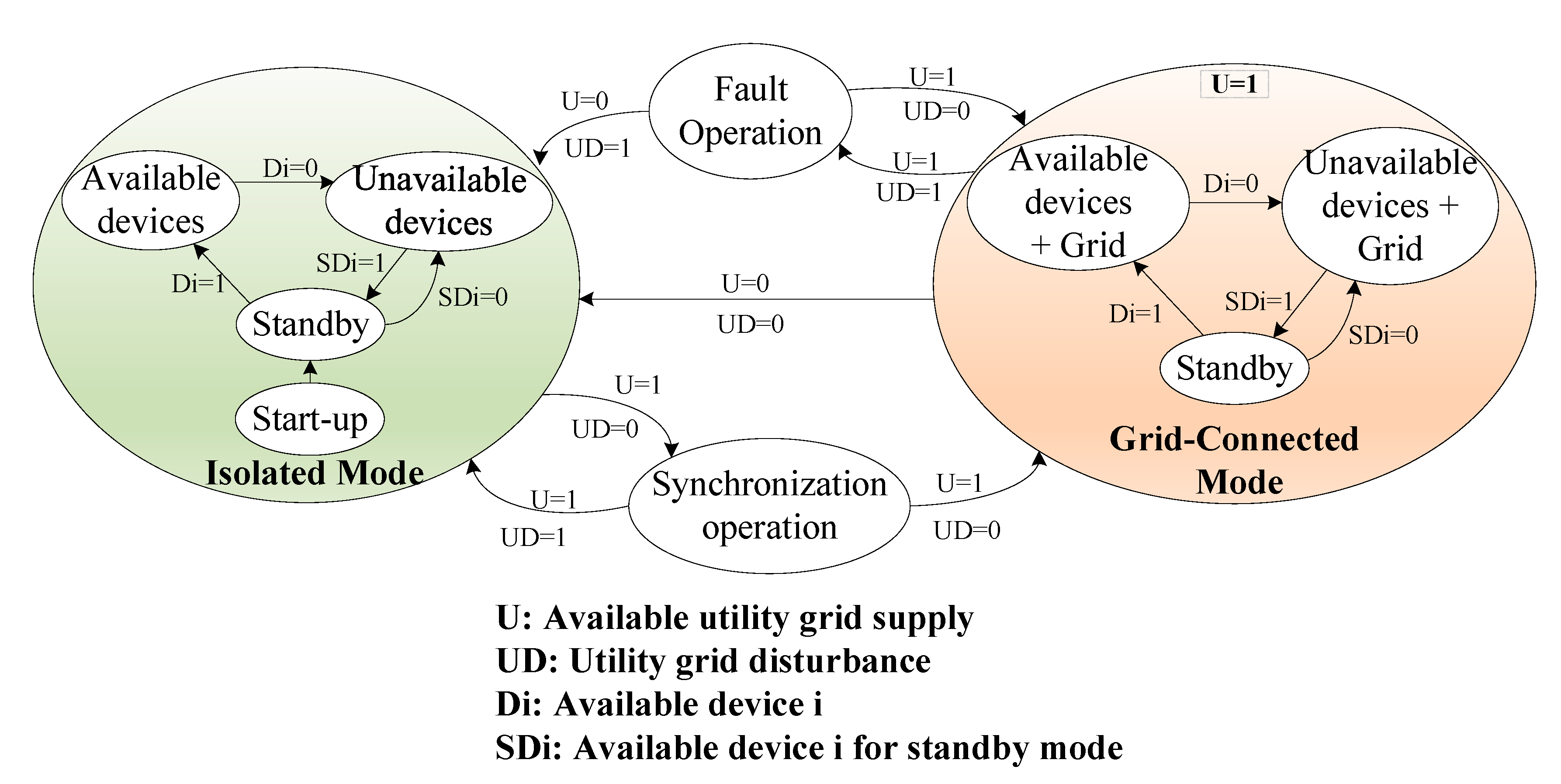
The Figure 2 shows the state diagram of MG operation considering the available/unavailable devices and the utility grid. In normal operation, the MG system is operated in the grid-connected mode to exchange power with the utility grid. The number of the available/unavailable devices is updated every time according to the status of all devices in the MG system. In case of faults, the MG is switched to the islanded mode. Similarly, the number of the available/unavailable devices is updated every time according to the status of all devices in this operation mode. The number of available devices along with their parameters is informed to the EMS for scheduling. Whenever the utility grid is available, the MG is switched to the grid-connected mode as soon as possible to optimize the operation cost and reduce load shedding amount during peak load intervals.
3. Auto-Configuration Function
3.1. Definition of Auto-Configuration Function
The auto-configuration function is defined as the capability of the MG system to automatically configure itself followed by any change in the system configuration. The devices can describe their capabilities to the auto-configurator agent and specify their services for monitoring and control. The auto-configuration function was developed taking into account the following sub-functions:
- Plug and play of smart appliances in smart house/building
- Registration/deregistration of devices owned by the MG operator
- Registration/deregistration of a home/building energy management system
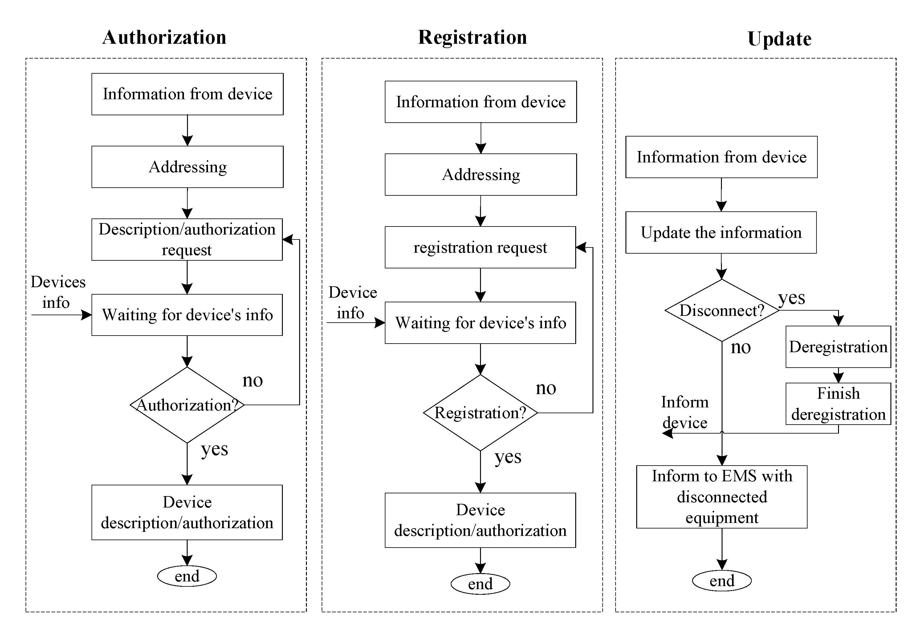
The flowchart of the auto-configuration function of an MG is shown in Figure 3. The main process of auto-configuration is includes authorization, registration/deregistration, and updating. Whenever devices are registered/deregistered, the information is sent to the EMS for rescheduling the operation of all the participating components.
The processes for sub-functions of the auto-configuration are represented in Figure 4. In these processes, the communication between the device agents and the auto-configurator agent has been shown in detail for authorization, registration, and updating.
3.2. Sniffer Diagram for Adding/Removing devices
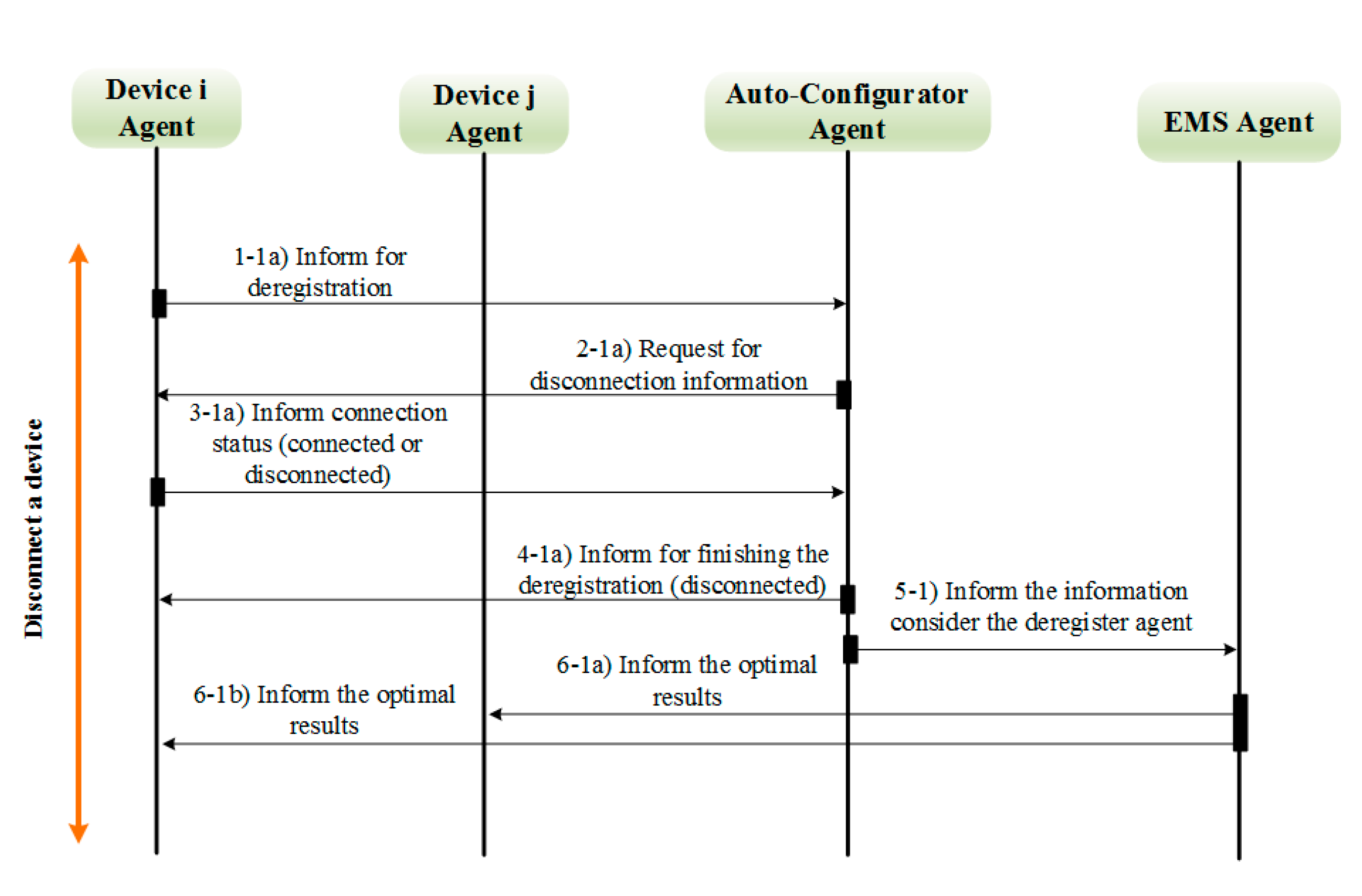
Figure 5 and Figure 6 show the sequence of data exchange among agents at the occurrence time of events, such as the change in the operation mode of MG or the change in the equipment status. The foundation for intelligent physical agents (FIPA) ACL is used for all messages in the proposed processing. Firstly, in order to register with the auto-configurator agent, each new device agent informs its address to the auto-configurator agent. A request message is sent to all the new device agents for authorization. Each device agent sends the device description to the auto-configurator agent for authorization and waits for registration request. Whenever the auto-configuration checks all the information of the new device agents, the requests for final registration are sent to all the device agents. The device agent informs its information for registration and waits a response message. Finally, all the information of the new devices is sent to the EMS agent after finishing the registration process. The EMS performs optimization and informs the optimal results to all the participating agents.
Similarly, whenever the auto-configurator agent receives the information of disconnection from a device agent. Confirmation for deregistration is requested by the auto-configurator agent. After receiving a confirmation, the auto-configurator agent performs deregistration and informs to EMS with updated information of the devices. Finally, EMS agent performs optimization and informs the new schedules to all the participating agents.
3.3. Operation Algorithm for EMS
Figure 7 represents the operation algorithm for energy management system. Firstly, the EMS receives the information of all available equipment and the utility grid from the auto-configurator agent as inputs for optimization problem. In case of the grid-connected mode, EMS performs optimization to minimize the operation cost with these available equipment and decides the amount of power exchange with the utility grid. The optimization results are informed to all the participating components at the end of the processing. Whenever auto-configurator agent informs the updated information of the number of registered/deregistered equipment along with their parameters, the EMS updates the information and rescheduling with the updating information. When the utility grid is unavailable, the MG system is changed to the islanded mode. In this mode, EMS performs optimization without the amount of exchange power with the utility grid. Whenever the local supply cannot fulfil the demand, the load shedding scheme should be considered to maintain the power balance in the MG system. In order to operate the MG system in an economical way, the information of the registered/deregistered equipment is also updated and is sent to the EMS by auto-configurator agent. The operation of all participating equipment is rescheduled and updated by EMS.
4. Mathematical Models
The main objective aims to minimize the total operation cost of the MG, as given by Equation (1). The first term of (1) contains generation cost, shut-down cost, and start-up cost of DG units. The second term contains the paying for importing power from the utility grid and the profit gained by exporting electricity to the utility grid. The penalty for load shedding in the islanded mode is represented in last term of the objective function:
Subject to
Constraint (3) guarantees that the power outputs of each DG unit is within the generation capacities. The start-up and shut-down status are decided based on the mode of DG units, as given in (5)–(6). Constraints (7)–(8) represent the ramp up and ramp down limits.
Constraint (9) is power balance equation which ensures that the sum of power generated by DG units, BESS unit, and the power exchange with the utility grid (in grid-connected mode) matches the total load consumption. In the islanded mode, the power balance is maintained by using its own resources. In case of having shortage power, the mismatch power between supply and consumption is fulfilled by performing load shedding. The power outputs of DG units and BESS units are control variables, while the RDG units are non-dispatchable. The power of BESS unit can be positive (discharging), negative (charging), or zero (idle). The power exchanged with the utility grid can be positive (selling power), negative (buying power), or zero. The power losses is sum of the BESS charging/discharging loss and line loss. The BESS charging/discharging loss is considerded as shown in (10)–(12) while the active power line loss can be calculated by using the following equation:
where Imn is the current magnitude flowing through the line between two buses m and n in the MG system [31]. MG is localized and small-scale power system and the length of line cable is short. Therefore, the resistance of the MG cable between two buses m and n (Rmn) is very small and the power line losses is neglectable in the MG system [21,31]. Therefor, power losses of lines are not considered in this study.
Constraints (10)–(11) present the charging and discharging limits of a BESS unit according to the value of SOC. Constraint (12) represents the SOC of a BESS, which is updated every interval based on the charging/discharging amount. Constraint (13) shows that the value of BESS at first interval is set to initial value. The operation bounds of BESS is constrained in (14).
5. Simulation Results
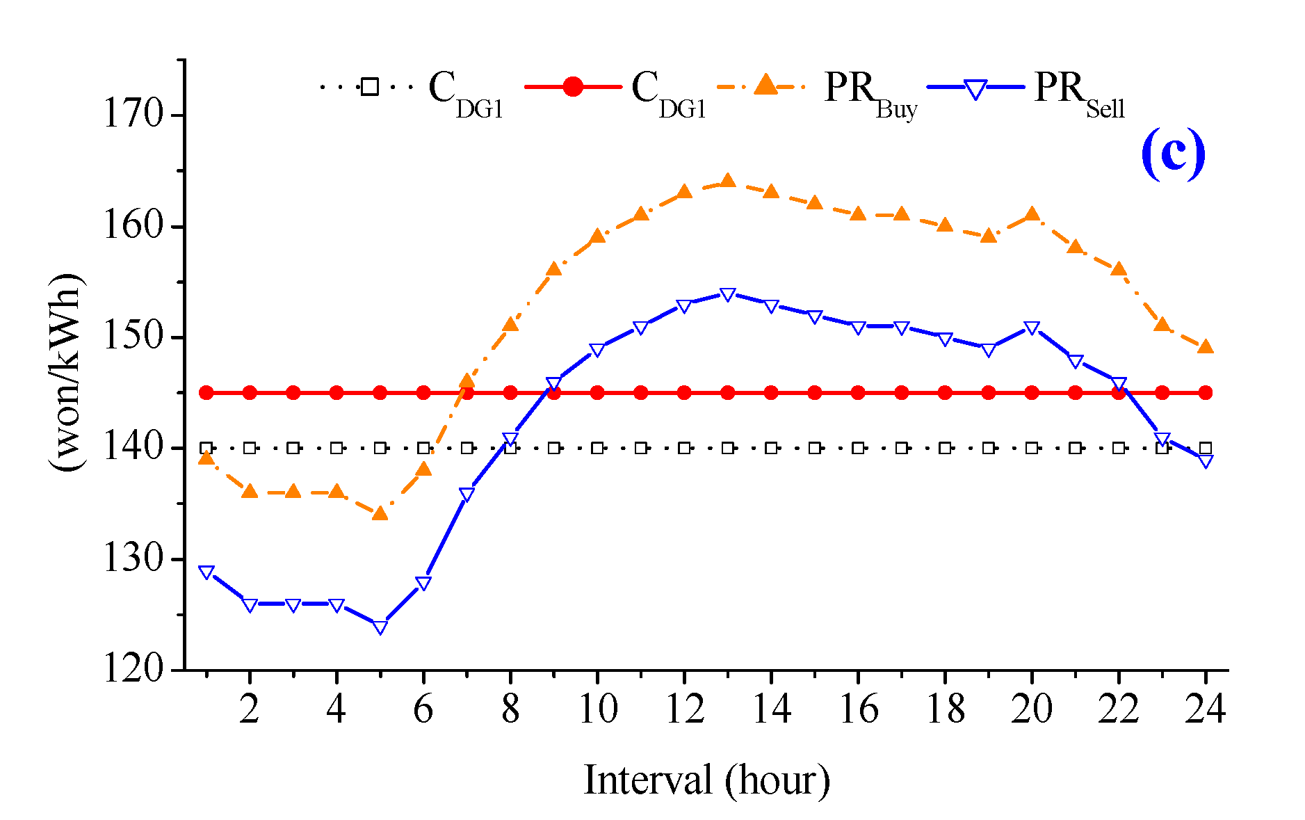
The proposed method has been implemented on a microgrid system, as shown in Figure 1. In this paper, diesel generators and BESSs are considered as the main power supply in the MG system. The detail parameters of DG units and BESS unit are summarized in Table 1. The output power of RDG units, the amount of load, and the market price signals are shown in Figure 8. The proposed model is formulated for 24 h with a 1-h time step. The proposed model has been implemented on a computer using Java, JADE [32] with integration of IBM ILOG CPLEX [33] with an Intel(R) Core i5(TM) 2500 CPU @ 3.30GHz and 8 GB of RAM memory and MATLAB/Simulink.
Figure 9 shows the scheduling of the MG considering the disconnection of DG1 at 8 h and reconnection of DG1 at 11 h. Therefore, DG1 is out of service from 8 h to 11 h. The auto-configurator updates the disconnection information of DG1 to the EMS at time interval 8. Then the EMS reschedules its remaining resources to operate the MG system in an economical way. From interval 1 to 7, the MG is operated based on the previous schedule, as shown in Figure 9.
At interval 8, DG1 is out of service therefore, the output power of DG1 is reduced from 60 kWh to zero. In order to maintain the power balance in the system, the output power of DG2 is increased to the maximum value, 50 kWh. The amount of buying power from the utility grid is also increased from zero to 34 kWh. The dynamic response for all components is shown in detail in Figure 10.
Similarly, at interval 11, DG1 is reconnected again to the MG system. The information of a new registration is informed to EMS agent by the auto-configurator agent. To operate the MG system in an economical way, the EMS considers the generation cost of new equipment and decides the output power of each resource. In this case, the output power of DG1 is set to the maximum values (60 kWh) to reduce the buying power from 58 kWh to 6 kWh at peak price interval. The dynamic response for all components is shown in detail in Figure 11.
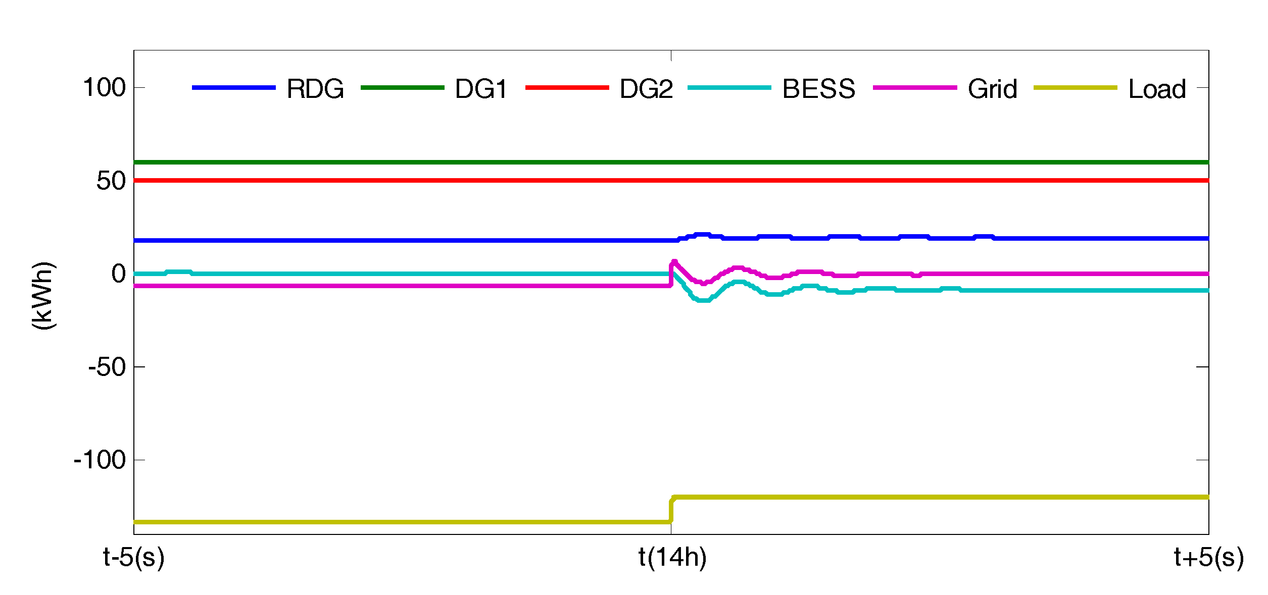
It is assumed that at interval 14, the MG is switched to the islanded mode. The auto-configurator agent deregisters with the market agent and the MG is disconnected from the utility grid. In this mode, The MG system cannot exchange power with the utility grid. Therefore, in order to maintain the power balance, load shedding is performed during some peak-time intervals. The new schedules for all components are shown in Figure 12. The EMS reschedules its resources to minimize the total operation cost and the amount of load shedding considering the islanded mode from interval 14. The output power of DG2 is adjusted to fulfill the load amount, as shown in Figure 12. However, in some peak load intervals, even though all DG units are set at the maximum values, the power supply cannot fulfill the load amount. Some load is shed to maintain the power balance in the MG system (intervals 18–23).
Figure 13 represents the response of all components when the MG switches to the islanded mode. Before interval 14, the buying power is set to 7 kWh. During interval 14, the selling power is set to 9 kWh, as shown in Figure 9. However, the MG system is operated in the islanded mode from interval 14. Therefore, the power exchange with the utility grid is reduce to zero and the surplus power is charged to BESS for reducing the load shedding amount in the peak-time intervals (intervals 20, 21).
Comparison of the amount of exchanged power with the utility grid for normal case and event cases is shown in Figure 14. The output power of DG units is decided by comparing the generation cost of DGs and market price. In normal operation case, the DG1 having low cost is used during interval 8 to 10. In the event case, we consider that the DG1 is out of service at 8 h and reconnect at 11 h. Therefore, the output power of DG1 is reduced to zero during three hours. The generation cost of DG2 is less than the market price, so DG2 is increased to fulfil the load amount. In case of having shortage amount, the MG has to import more electrical power from the utility grid. Therefore, in event case, the total power exchange with the utility grid increases compared with the normal case, as shown in Figure 14 from interval 8 to 10.
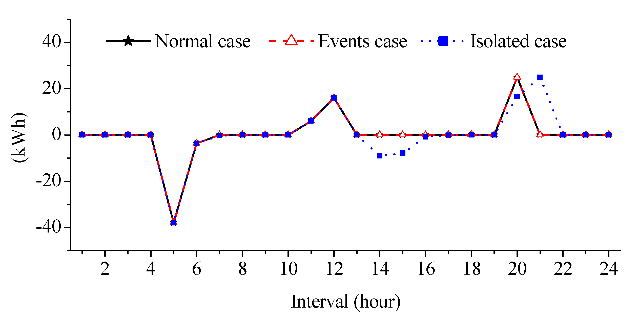
A comparison of the amount of BESS charging/ discharging in the three different cases is shown in Figure 15. The amount of BESS charging and discharging is same in both normal and event cases due to the short duration of event time. However, in islanded case, BESS always charges surplus power as much as possible to fulfill the load amount at peak load intervals. Therefore, after discharging at intervals 11 and 12, BESS is fully charged at intervals 14 and 15 for using in future intervals. During peak load intervals, BESS has discharged more power for reducing the load shedding amount, as shown in Figure 15, intervals 20 and 21.
6. Conclusions
In this paper, an auto-configuration function is proposed for integration of new devices and updating the operation status of existing devices, which is followed by a rescheduling process. The auto-configurator can assist the EMS for minimizing the operation cost while reducing load shedding amount. By applying the proposed algorithm with the integration of auto-configuration function, the MG system can update the number of the participating agents (devices) along with their parameters in the MG system. In this way, EMS is able to adjust the schedules of all components by using the received information from the auto-configurator. Additionally, the response of the system has also been analyzed considering the connection/disconnection of a device. After the occurrence of an event (connect/disconnect a device), EMS receives the system information from the auto-configurator agent and reschedules all the participating agents. The load shedding scheme is implemented to maintain the power balance in the islanded mode. It can be observed from the simulation results that the auto-configuration function can improve the efficiency of the MG system integration and operation management.
However, in case of connecting new loads or disconnecting existing generators, the microgrid should require more power supply from the utility grid to cover the load amount. Therefore, the grid power profile is increased and it could make a peak power in the utility grid. It is necessary to develop an algorithm for tradeoff between improving MG system reliability and avoiding a peak power in the utility grid. Auto-configuration function with consideration of grid disturbance issues wills a suitable extension of this paper.
Acknowledgments
This work was supported by Incheon National University Research Grant in 2016.
Author Contributions
Van-Hai Bui conceived and designed the experiments; Akhtar Hussain performed the experiments and analyzed the data; Hak-Man Kim revised and analyzed the results; Van-Hai Bui wrote the paper.
Conflicts of Interest
The authors declare no conflict of interest.
Abbreviations
| Index of time, running from 1 to | |
| T | Set of time intervals |
| i | Index of generator, running from 1 to |
| I | Set of generators |
| l | Index of load, running from 1 to |
| L | Set of loads |
| m | Index of bus, running from 1 to |
| M | Set of buses |
| Production cost of unit i | |
| Min/max production limits of unit i | |
| Start-up cost of unit i | |
| Shut-down cost of unit i | |
| Buying price at t | |
| Selling price at t | |
| , | Forecasted output of PV cell & wind turbine |
| , | Losses for charging/discharging of BESS |
| Capacity of BESS | |
| Total amount of load l at t | |
| Minimum value of state of charge of BESS | |
| Maximum value of state of charge of BESS | |
| Initial value of state of charge of BESS | |
| On or off mode of unit i at t | |
| Operation mode at t | |
| Start-up status of unit i at t | |
| Shut-down status of unit i at t | |
| Generation amount of unit i at t | |
| Charging/discharging power of BESS at t | |
| , | Buying/selling power of MG at t |
| State of charge of BESS at t | |
| Penalty for load shedding at t | |
| Total load shedding amount at t | |
| Total active power line loss at t | |
| The resistance of the cable between buses m and n | |
| The magnitude of the current flows through the line between buses m and n |
References
- Ou, T.C.; Hong, C.M. Dynamic operation and control of microgrid hybrid power systems. Energy 2014, 66, 314–323. [Google Scholar] [CrossRef]
- Ou, T.C.; Lu, K.H.; Huang, C.J. Improvement of transient stability in a hybrid power multi-system using a designed NIDC (Novel Intelligent Damping Controller). Energies 2017, 10, 488. [Google Scholar] [CrossRef]
- Ou, T.C.; Su, W.F.; Liu, X.Z.; Huang, S.J.; Tai, T.Y. A modified bird-mating optimization with hill-climbing for connection decisions of transformers. Energies 2016, 9, 671. [Google Scholar] [CrossRef]
- Ou, T.C. A novel unsymmetrical faults analysis for microgrid distribution systems. Int. J. Electr. Power. Energy Syst. 2012, 43, 1017–1024. [Google Scholar] [CrossRef]
- Ou, T.C. Ground fault current analysis with a direct building algorithm for microgrid distribution. Int. J. Electr. Power. Energy Syst. 2013, 53, 867–875. [Google Scholar] [CrossRef]
- Zamani, M.A.; Sidhu, T.S.; Yazdani, A. Investigations into the control and protection of an existing distribution network to operate as a microgrid: A case study. IEEE Trans. Ind. Electron. 2014, 61, 1904–1915. [Google Scholar] [CrossRef]
- Kim, H.M.; Kinoshita, T.; Shin, M.C. A multiagent system for autonomous operation of islanded microgrids based on a power market environment. Energies 2010, 3, 1972–1990. [Google Scholar] [CrossRef]
- Hatziargyriou, N.; Asano, H.; Iravani, R.; Marnay, C. Microgrids. IEEE Power Energy Mag. 2007, 5, 78–94. [Google Scholar] [CrossRef]
- Bui, V.H.; Hussain, A.; Nguyen, T.T.; Kim, H.M. Real-time optimization for microgrid operation based on auto-configuration in grid-connected mode. In Proceedings of the 2016 IEEE International Conference, Vietnam, Hanoi, 14–16 November 2016. [Google Scholar]
- Kim, H.M.; Lim, Y.; Kinoshita, T. An intelligent multiagent system for autonomous microgrid operation. Energies 2012, 5, 3347–3362. [Google Scholar] [CrossRef]
- Bui, V.H.; Hussain, A.; Kim, H.M. Optimal microgrid operation considering auto-configuration in islanded mode. In Proceedings of the 2016 IEEE International Conference, Vietnam, Hanoi, 14–16 November 2016. [Google Scholar]
- Katiraei, F.; Iravani, R.; Hatziargyriou, N.; Dimeas, A. Microgrid management. IEEE Power Energy Mag. 2008, 6, 54–65. [Google Scholar] [CrossRef]
- Su, W.; Wang, J. Energy management systems in microgrid operations. Electr. J. 2012, 25, 45–60. [Google Scholar] [CrossRef]
- Hussain, A.; Bui, V.H.; Kim, H.M. A resilient and privacy-preserving energy management strategy for networked microgrids. IEEE Trans. Smart Grid 2017, 99, 1. [Google Scholar] [CrossRef]
- Bui, V.H.; Hussain, A.; Kim, H.M. A multiagent-based hierarchical energy management strategy for multi-microgrids considering adjustable power and demand response. IEEE Trans. Smart Grid 2017, 99, 1. [Google Scholar] [CrossRef]
- Deng, W.; Pei, W.; Shen, Z.; Zhao, Z.; Qu, H. Adaptive micro-grid operation based on IEC 61850. Energies 2015, 8, 4455–4475. [Google Scholar] [CrossRef]
- Hussain, A.; Bui, V.H.; Kim, H.M. Robust optimization-based scheduling of multi-microgrids considering uncertainties. Energies 2016, 9, 278. [Google Scholar] [CrossRef]
- Mohan, V.; Suresh, R.; Singh, J.G.; Ongsakul, W.; Madhu, N. Microgrid energy management combining sensitivities, interval and probabilistic uncertainties of renewable generation and loads. IEEE J. Emerg. Sel. Top. Circuits Syst. 2017, 7, 262–270. [Google Scholar] [CrossRef]
- Deng, W.; Pei, W.; Qi, Z. Microgrid information exchange based on IEC 61850. Autom. Electr. Power Syst. 2013, 37, 6–11. [Google Scholar]
- Gomez-Sanz, J.J.; Garcia-Rodriguez, S.; Cuartero-Soler, N.; Hernandez-Callejo, L. Reviewing microgrids from a multi-agent systems perspective. Energies 2014, 7, 3355–3382. [Google Scholar] [CrossRef]
- Bogaraj, T.; Kanakaraj, J. Intelligent energy management control for independent microgrid. Sādhanā 2016, 41, 755–769. [Google Scholar] [CrossRef]
- Dimeas, A.L.; Hatziargyriou, N.D. Operation of a multiagent system for microgrid control. IEEE Trans. Power Syst. 2005, 20, 1447–1455. [Google Scholar] [CrossRef]
- Yu, X.; Wang, F.; Huang, A.Q. Power management strategy for plug and play DC microgrid. In Proceedings of the 2012 3rd IEEE PES International Conference, Berlin, Germany, 14–17 October 2012. [Google Scholar]
- Hou, C.; Hu, X.; Hui, D. Plug and play power electronics interface applied in microgrid. In Proceedings of the 2011 4th International Conference, Weihai, China, 6–9 July 2011. [Google Scholar]
- Tucci, M.; Riverso, S.; Ferrari-Trecate, G. Line-independent plug-and-play controllers for voltage stabilization in dc microgrids. IEEE Trans. Control Syst. Technol. 2017, PP, 1–9. [Google Scholar] [CrossRef]
- Ito, Y.; Zhongqing, Y.; Akagi, H. DC microgrid based distribution power generation system. In Proceedings of the 4th International Power Electronics and Motion Control Conference (IPEMC 2004), Xi’an, China, 14–16 August 2004. [Google Scholar]
- Crisostomi, E.; Liu, M.; Raugi, M.; Shorten, R. Plug-and-play distributed algorithms for optimized power generation in a microgrid. IEEE Trans. Smart Grid 2014, 5, 2145–2154. [Google Scholar] [CrossRef]
- Laaksone, H.; Kauhaniemi, K. Fault type and location detection in islanded microgrid with different control methods based converters. In Proceedings of the 19th International Conference on Electricity Distribution, Vienna, Austria, 21–24 May 2007. [Google Scholar]
- Nikkhajoei, H.; Lasseter, R.H. Microgrid protection. In Proceedings of the IEEE 2007 Power Engineering Society General Meeting, Tampa, FL, USA, 24–28 June 2007. [Google Scholar]
- FIPA, The Foundation for Intelligent Physical Agents standards. Available online: http://www.fipa.org (accessed on 7 September 2017).
- Zehir, M.A.; Batman, A.; Sonmez, M.A.; Font, A.; Tsiamitros, D.; Stimoniaris, D.; Kollatou, T.; Bagriyanik, M.; Ozdemir, A.; Dialynas, E. Impacts of microgrids with renewables on secondary distribution networks. Appl. Energy 2017, 201, 308–319. [Google Scholar] [CrossRef]
- Java Agent Development Environment (JADE). Available online: http://jade.tilab.com (accessed on 7 September 2017).
- IBM ILOG CPLEX V12.6 User’s Manual for CPLEX 2015, CPLEX Division; ILOG: Incline Village, NV, USA, 2015; Available online: https://www.ibm.com/support/knowledgecenter/SSSA5P_12.6.2/ilog.odms.studio.help/pdf/usrcplex.pdf (accessed on 7 September 2017).
Figure 1.
Microgrid system configuration.
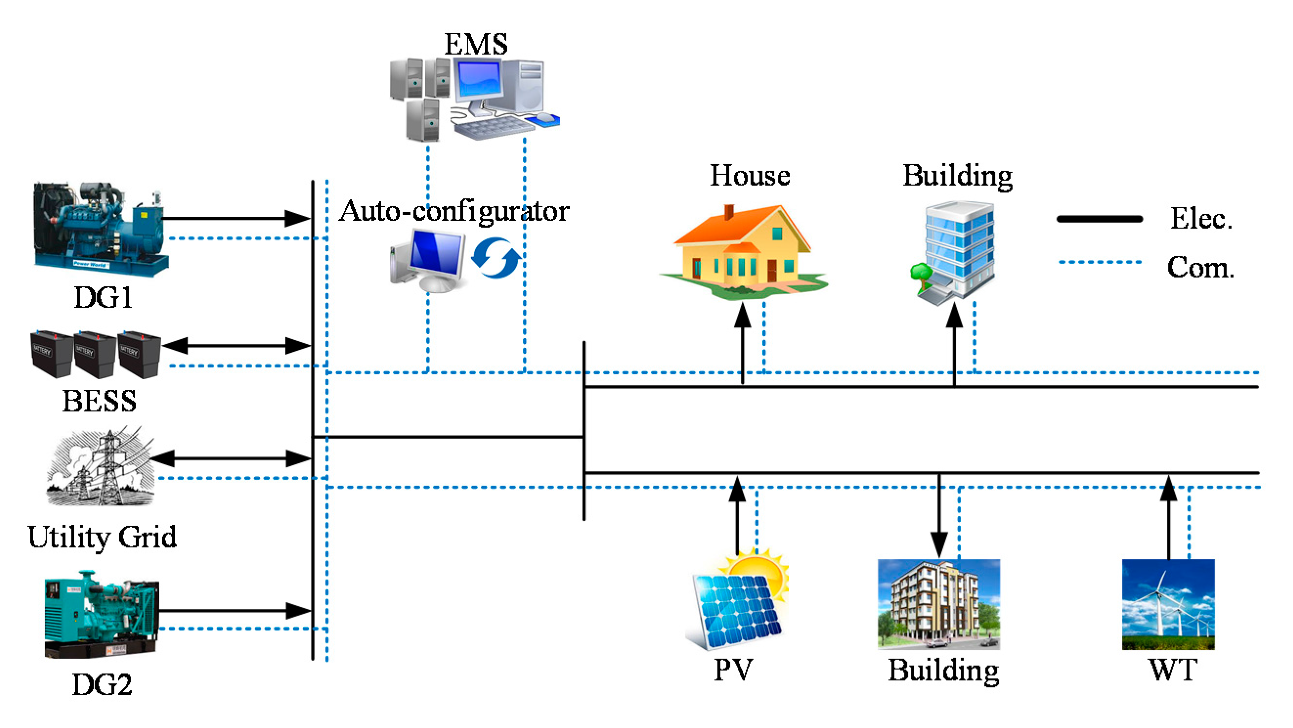
Figure 2.
The state diagram of microgrid operation.

Figure 3.
Main sub-functions of auto-configuration.

Figure 4.
Flowchart of the sub-functions of auto-configuration.

Figure 5.
Sniffer diagram for adding new devices.
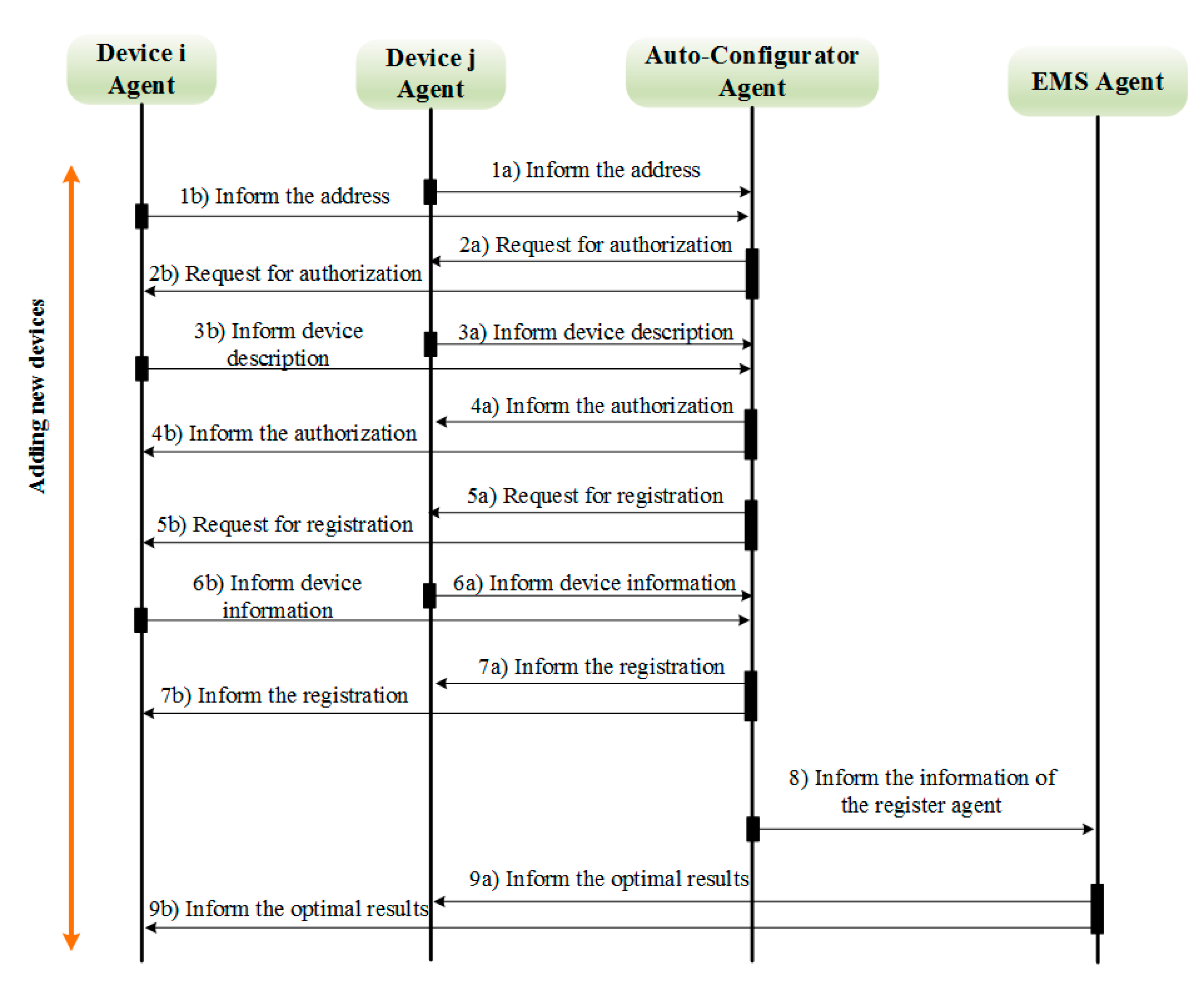
Figure 6.
Sniffer diagram for disconnecting a device.

Figure 7.
The proposed operation algorithm for EMS.
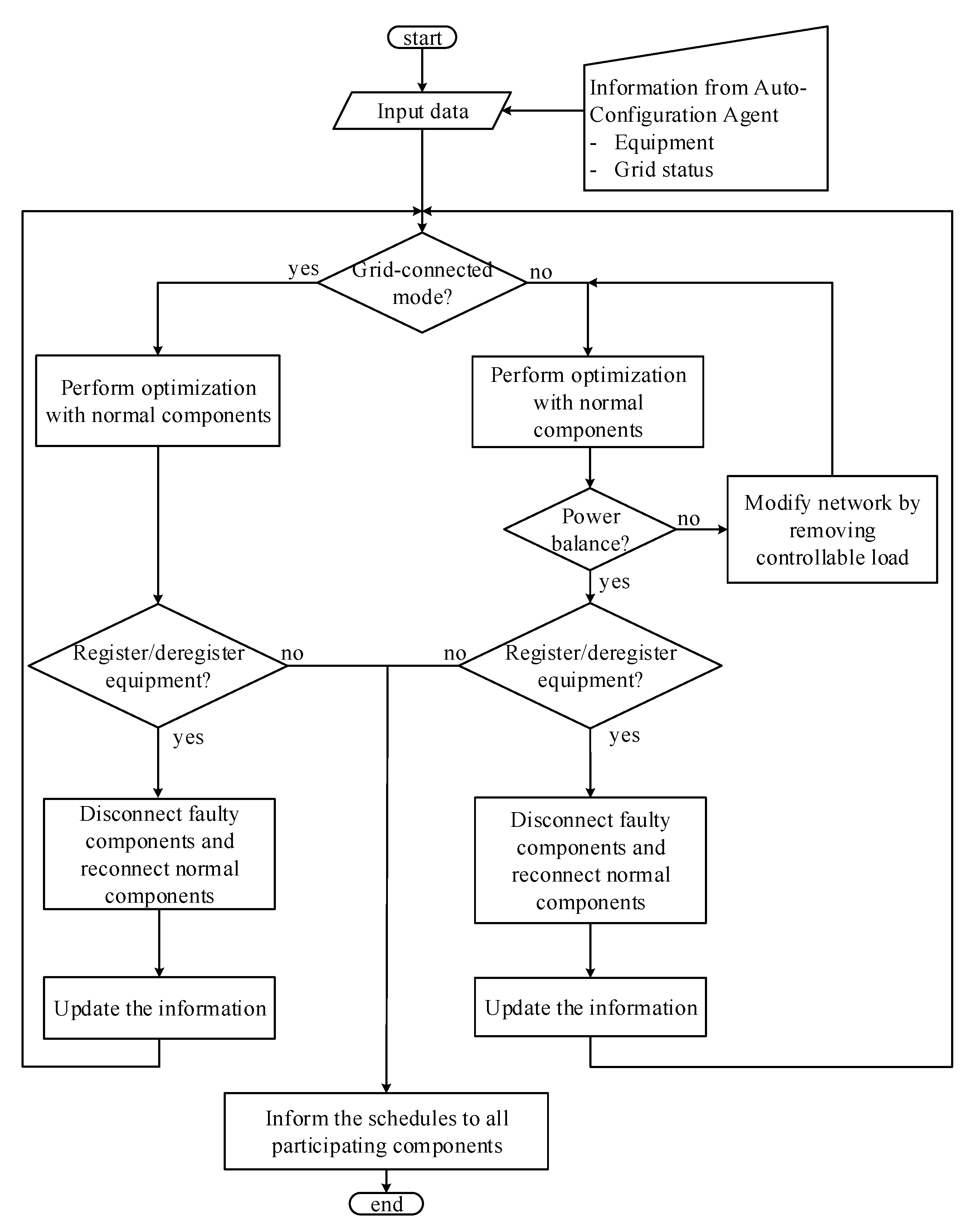
Figure 8.
Input data: (a) RDG units output; (b) load amount; (c) market price signals.
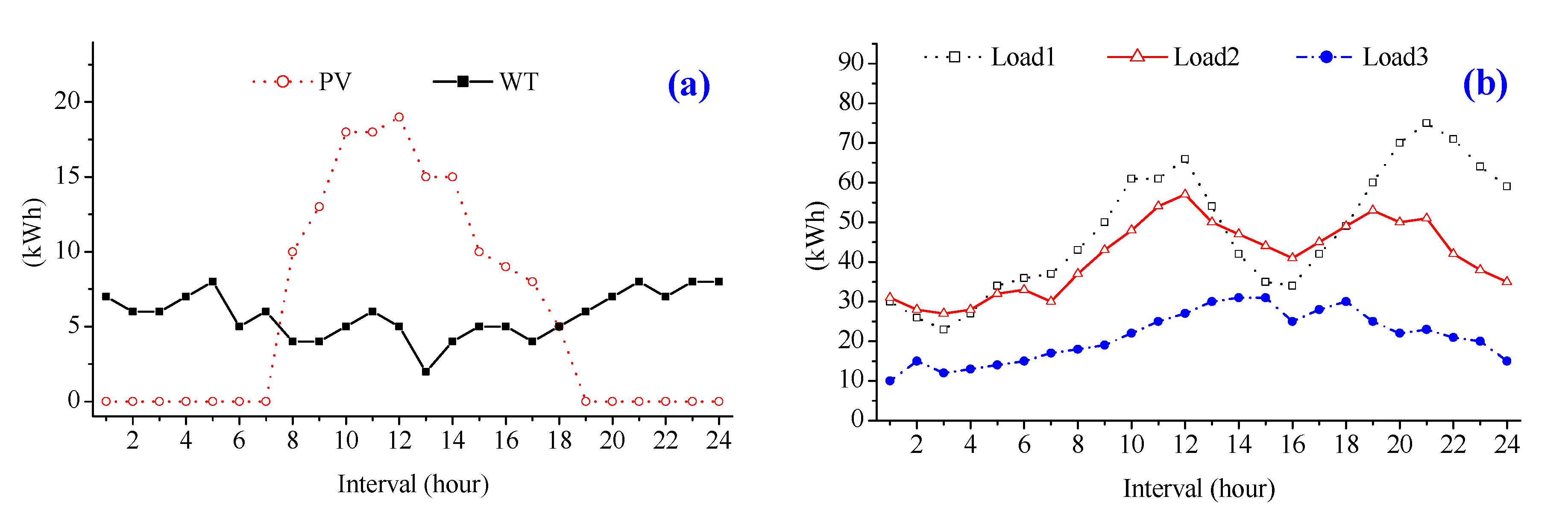

Figure 9.
Schedule for all components considering the events at 8 h and 10 h.
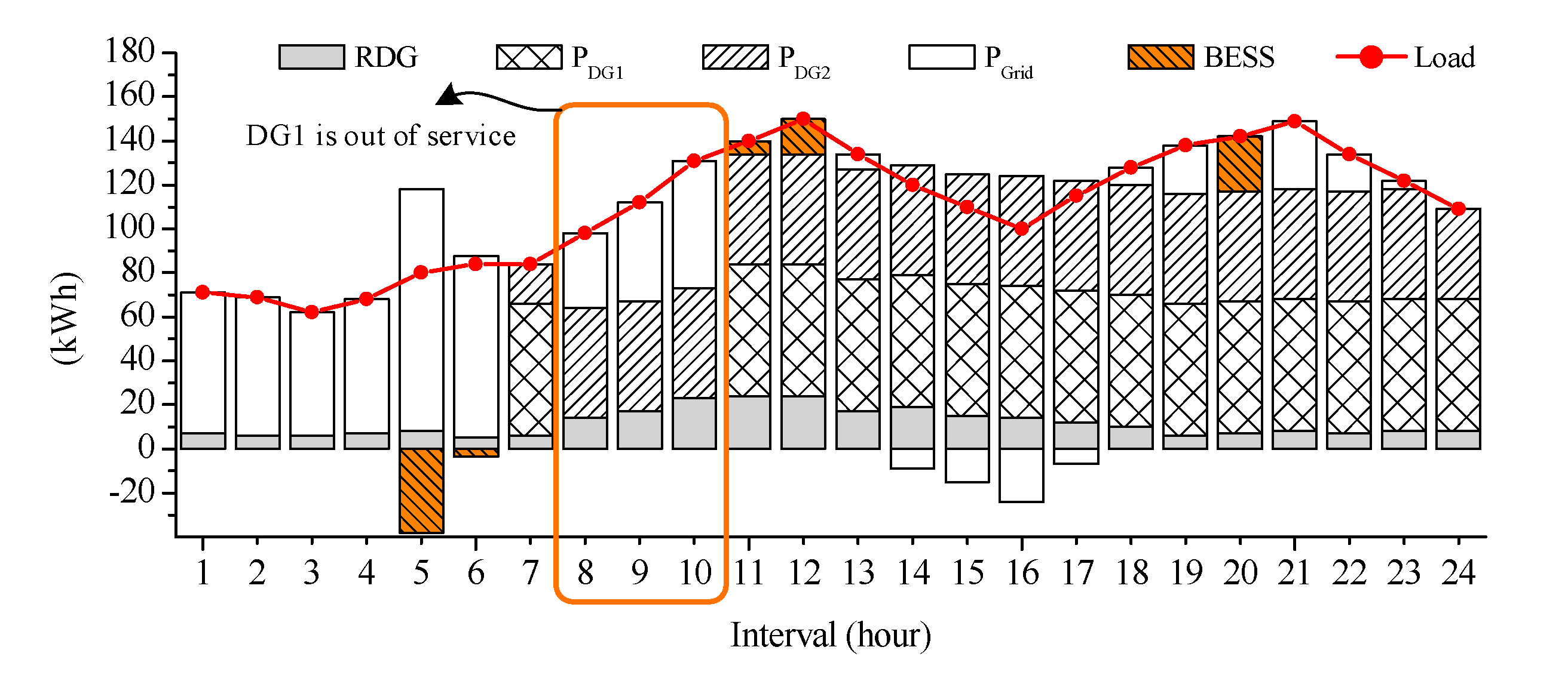
Figure 10.
The response of all components in case of disconnecting DG1 at 8 h.
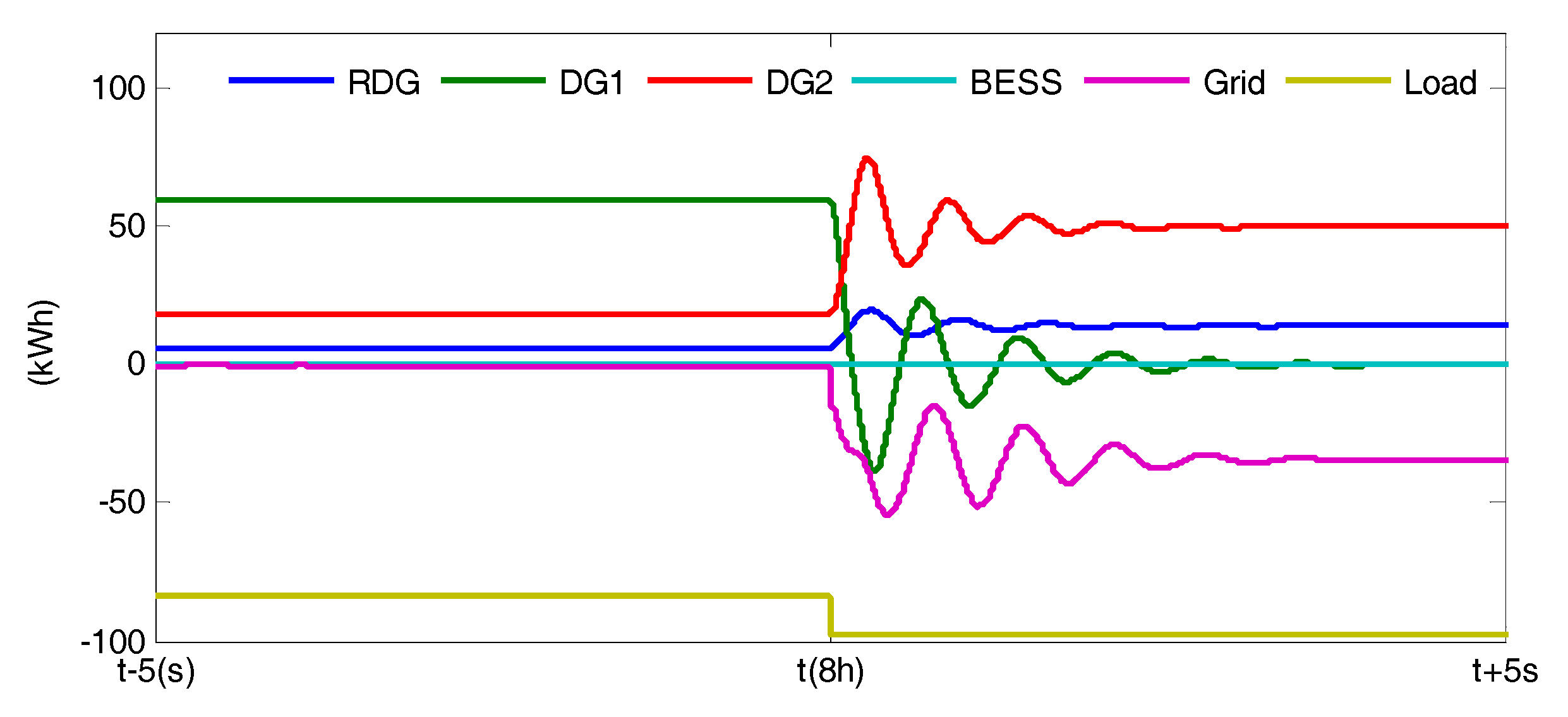
Figure 11.
The response of all components in case of reconnecting DG1 at 11 h.

Figure 12.
Schedule for all components considering the islanded mode from 14 h.
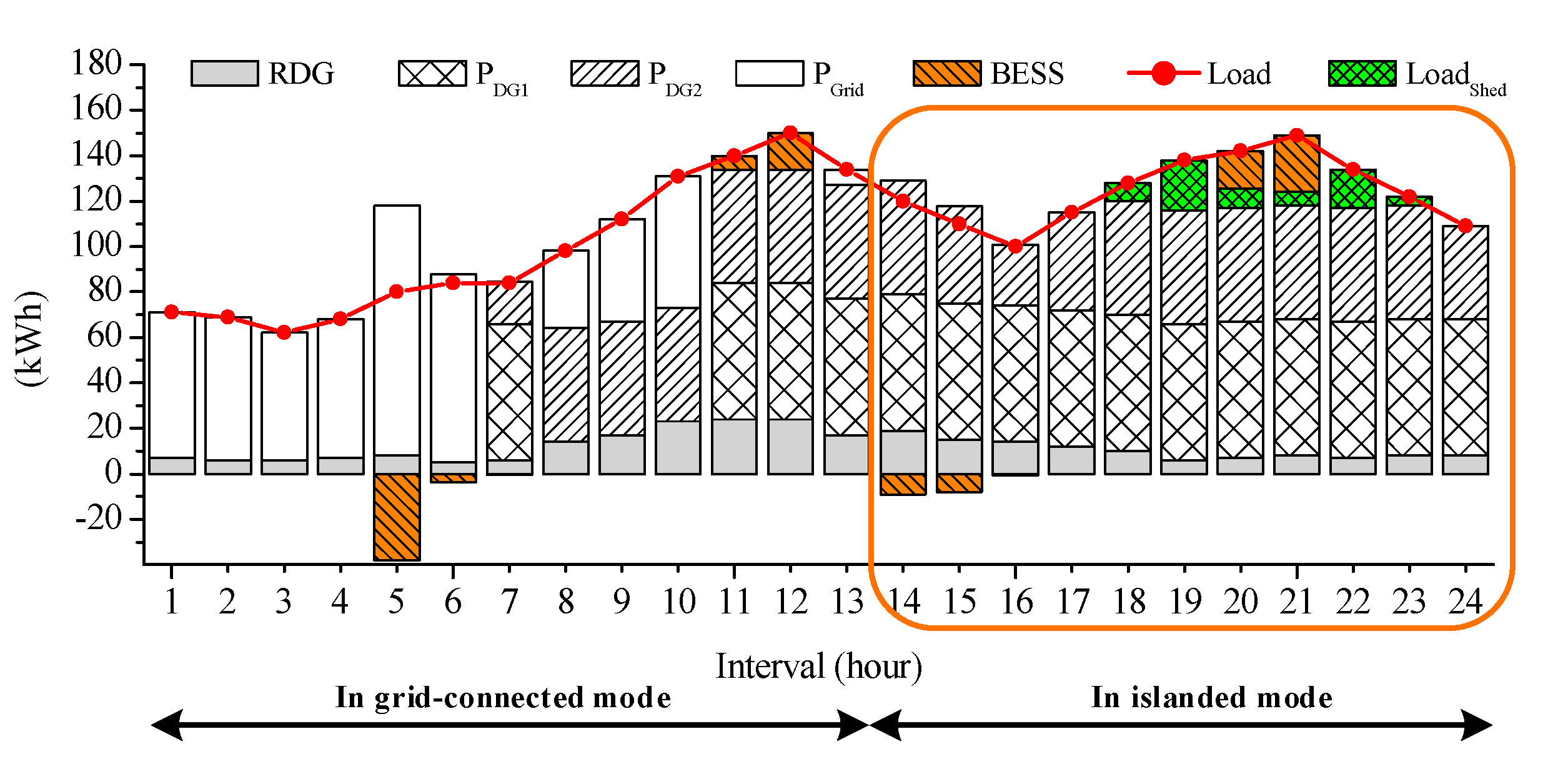
Figure 13.
The response of all components when the MG switches to the islanded mode at 14 h.

Figure 14.
Comparison of the amount of power exchange with the utility grid.
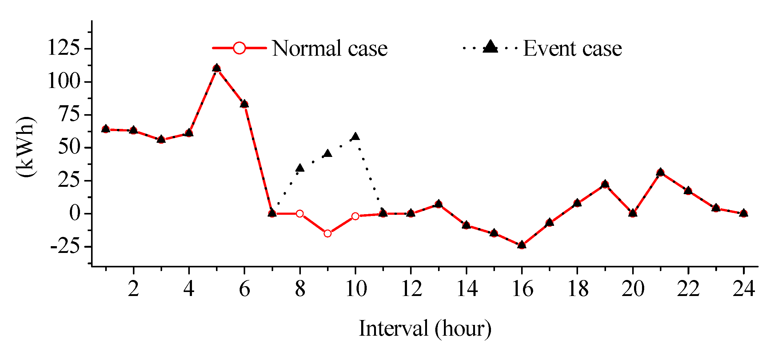
Figure 15.
Comparison of the amount of power exchange with the utility grid.


Table 1.
Parameters related to DG units and BESS of the MG system.
| Parameters | DG1 | DG2 | Parameters | BESS |
|---|---|---|---|---|
| Cost/kWh | 140 | 145 | Capacity | 50 |
| Start-up cost | 200 | 200 | Min | 0 |
| Shut-down cost | 100 | 100 | Initial | 10 |
| Min | 0 | 0 | Char. Loss (%) | 5 |
| Max | 60 | 50 | Dis. Loss (%) | 5 |
© 2017 by the authors. Licensee MDPI, Basel, Switzerland. This article is an open access article distributed under the terms and conditions of the Creative Commons Attribution (CC BY) license (http://creativecommons.org/licenses/by/4.0/).
Share and Cite
MDPI and ACS Style
Bui, V.-H.; Hussain, A.; Kim, H.-M. Optimal Operation of Microgrids Considering Auto-Configuration Function Using Multiagent System. Energies 2017, 10, 1484. https://doi.org/10.3390/en10101484
AMA Style
Bui V-H, Hussain A, Kim H-M. Optimal Operation of Microgrids Considering Auto-Configuration Function Using Multiagent System. Energies. 2017; 10(10):1484. https://doi.org/10.3390/en10101484
Chicago/Turabian StyleBui, Van-Hai, Akhtar Hussain, and Hak-Man Kim. 2017. "Optimal Operation of Microgrids Considering Auto-Configuration Function Using Multiagent System" Energies 10, no. 10: 1484. https://doi.org/10.3390/en10101484
Note that from the first issue of 2016, this journal uses article numbers instead of page numbers. See further details here.