
Performance Analysis of Thermoelectric Based Automotive Waste Heat Recovery System with Nanofluid Coolant

1
Hubei Key Laboratory of Advanced Technology for Automotive Components, Wuhan University of Technology, Wuhan 430070, China
2
Institute of Power Machinery and Vehicular Engineering, Zhejiang University, Hangzhou 310027, China
3
Hubei Collaborative Innovation Center for Automotive Components Technology, Wuhan University of Technology, Wuhan 430070, China
4
School of Mechanical and Electronic Engineering, Wuhan University of Technology, Wuhan 430070, China
*
Author to whom correspondence should be addressed.
Energies 2017, 10(10), 1489; https://doi.org/10.3390/en10101489
Submission received: 3 August 2017
/
Revised: 31 August 2017
/
Accepted: 20 September 2017
/
Published: 26 September 2017
(This article belongs to the Section I: Energy Fundamentals and Conversion)
Abstract
:Output performance of a thermoelectric-based automotive waste heat recovery system with a nanofluid coolant is analyzed in this study. Comparison between Cu-Ethylene glycol (Cu-EG) nanofluid coolant and ethylene glycol with water (EG-W) coolant under equal mass flow rate indicates that Cu-EG nanofluid as a coolant can effectively improve power output and thermoelectric conversion efficiency for the system. Power output enhancement for a 3% concentration of nanofluid is 2.5–8 W (12.65–13.95%) compared to EG-Water when inlet temperature of exhaust varies within 500–710 K. The increase of nanofluid concentration within a realizable range (6%) has positive effect on output performance of the system. Study on the relationship between total area of thermoelectric modules (TEMs) and output performance of the system indicates that optimal total area of TEMs exists for maximizing output performance of the system. Cu-EG nanofluid as coolant can decrease optimal total area of TEMs compared with EG-W, which will bring significant advantages for the optimization and arrangement of TEMs whether the system space is sufficient or not. Moreover, power output enhancement under Cu-EG nanofluid coolant is larger than that of EG-W coolant due to the increase of hot side heat transfer coefficient of TEMs.
1. Introduction
Due to the worldwide shortage of oil resources and environmental issues, energy saving and automotive emission reduction have attracted much attention in recent years. For the traditional internal combustion engine (ICE), 30–45% heat from fuel combustion is discharged into the surroundings by exhaust gas, which causes a great waste of energy and accelerates the deterioration of the environment [1,2,3]. One of the best solutions for these problems is to recover waste heat contained in exhaust gas. Vazquez et al. [4] indicates that if 6% of waste heat is recovered from exhaust gas, the fuel consumption rate of an ICE would decline by 10%.
Liang et al. [5] summarized all existing waste heat recovery technologies, such as Organic Rankine Cycle (ORC), turbocharging, etc. As for ORC, in spite of its relatively high thermal efficiency, it is not currently suitable for vehicle use because of its complicated structure and large size. Due to the requirement of relatively high exhaust gas temperature, turbocharging only have potential for the fuel saving under ICE high-load condition [6]. Liang et al. [5] concluded that with lots of advantages such as its simple structure, no moving parts, environment friendliness, extremely low noise, and long working hours, the thermoelectric generator (TEG) is one of the most promising methods for recovering ICE waste heat in the future.
Many studies on TEG technology for ICE waste heat recovery have been conducted. Robert J. Stevens et al. [7] designed a thermoelectric generating system on the exhaust pipe of a heavy-duty truck, and this system could recover 16% of waste heat of the exhaust with a conversion efficiency of 3–5%. Liu et al. [8] constructed a new automotive exhaust-based thermoelectric generator called the “four-TEGs” system and assembled it into the prototype vehicle called “Warrior”. A performance of 201.7 V (open circuit voltage)/944 W was obtained with a system efficiency of 1.85%. Car manufacture Hi-Z in the US succeeded in recovering waste heat from the exhaust using thermoelectric modules (TEMs). However, experimental result showed that the conversion efficiency was lower than 5% [9]. It can be found from these studies that thermoelectric generating technology is confined to a low conversion efficiency of approximately 5% in general. Thus, main challenge of applying TEG technology for ICE waste heat recovery is to improve the conversion efficiency of TEG system.
Currently, the endeavor to improve the conversion efficiency of the TEG system has concentrated on two aspects. Some focused on the efficiency of the thermoelectric material. However, although thermoelectric materials with high performance have been developed [10,11,12,13], commercial high-efficient thermoelectric modules are still not available. Another way is to maximize the temperature gradient across the embedded thermoelectric modules through system configuration optimization and heat transfer process intensification. Ahmet Z. Sahin et al. [14] studied effect of the leg length and width of TEMs on power output and conversion efficiency for the generating system with Bi2Te3 materials. Zhiqiang Niu et al. [15] established a 3D model to assess impact of the size of exhaust flow channel and the angle of fins in heat exchanger on TEG system. Simon Belanger et al. [16] optimized the internal structure of a commonly used heat exchanger and investigated the effect of TEMs quantity and circuit current on output performance of TEG system. Tongcai Wang et al. [17] designed a new heat exchanger filled with metal foam for TEG system, which realized a high heat transfer efficiency of 83.6% between hot air and coolant and increased output voltage. Yuchao Wang et al. [18] indicated that water-cooling was more competitive than air-cooling in a TEG system. Moreover, considering the limited size of exhaust flow channel and pressure, as well as the difficulty of enhancing heat transfer between the high-temperature exhaust and hot side of TEMs, more efforts should be put on the heat transfer enhancement between cold side of TEMs and coolant.
As to enhance heat transfer between cold side of TEMs and coolant, applying nanofluid as coolant is an attractive method. Nanofluids refer to fluids containing thermally conducting nanometer-sized solid particles [19], and are known to possess novel properties that make them have great potential in heat transfer applications. The promising features of nanofluids are high thermal conductivity due to much higher thermal conductivity of metals and metallic oxide nanoparticles than that of liquids (based fluid) and micro motions of nanoparticles in based fluid, which will lead to promising heat transfer performance of nanofluid. Meanwhile, due to their nanometer size, nanoparticles can be dispersed into the base fluids stably and thereby without problems such as abrasion and clogging. Thus, nanofluids can be treated as an excellent coolant in thermoelectric-based automotive waste heat recovery system. Since Choi et al. [19] proposed the conception of nanofluid with excellent heat transfer performance, many studies on the application of nanofluid for heat transfer enhancement have been conducted in recent years. Tzeng et al. [20] added CuO and Al2O3 nanoparticles into engine oil, and the results showed that two types of nanofluid enhanced cooling effect of automotive power transmission system and avoided high thermal stress of components. Kulkarni et al. [21] adopted Al2O3-EG nanofluid as a coolant for water jackets of a diesel generator, which obviously strengthened the cooling effect. S.M. Peyghambarzadeh et al. [22] studied the cooling effects of pure water, pure EG, Al2O3-water nanofluid, and Al2O3-EG nanofluid for a vehicle radiator and results showed that nanofluid had a 40% increase on cooling effect than base fluid. Although there has been previous research on the heat transfer performance of nanofluid, to the best of our knowledge, the influence of nanofluid as coolant on the performance of TEG has not been previously investigated.
At present, the coolant used in engines is EG-W. In order to compare with traditional coolant, we choose EG as the base fluid. Cu, CuO, Al, and Al2O3 are commonly used nanoparticles dispersed into EG-based fluid. Due to the much higher thermal conductivity of Cu-EG naofluid than the others, Cu-EG nanofluid was chosen as the new coolant in this study.
The present work studied the performance of a thermoelectric-based automotive waste heat recovery system with nanofluid coolant. Temperature distribution of thermoelectric modules, power output, and conversion efficiency for TEG system were obtained through simulating calculation. Affecting factors on the system performance, such as inlet temperature of exhaust gas, concentration of nanofluid, and total area of TEMs, are discussed in detail. Comparative analysis has also been carried out between Cu-EG nanofluid and traditional EG-W.
2. Mathematical Model
Waste heat contained in exhaust gas is transferred from the hot side to the cold side of TEMs and is finally taken away by the coolant. This heat transfer process is vital for the performance of the TEG system. Due to the complexity of this process, some hypotheses are made for simplifying the mathematical model as follows:
- (1)
- The heat transfer process is steady;
- (2)
- All the TEMs in the system are in series. Geometric configurations properties of P-type and N-type materials are identical, and physical properties of each P-type legs are identical, as well as the N-type legs;
- (3)
- Air between TEMs and heat exchangers are omitted because it is quite small. Thermal radiation is not taken into consideration. Contact resistance between TEMs and heat exchangers, thermal resistance perpendicular to flow direction of fluid, and Thomson effect are also omitted;
- (4)
- The external load resistance is equal to the internal resistance;
- (5)
- Thermoelectric material used in this study is Bi2Te3, its thermoelectric parameters are constants, and Table 1 presents the basic calculation parameters.
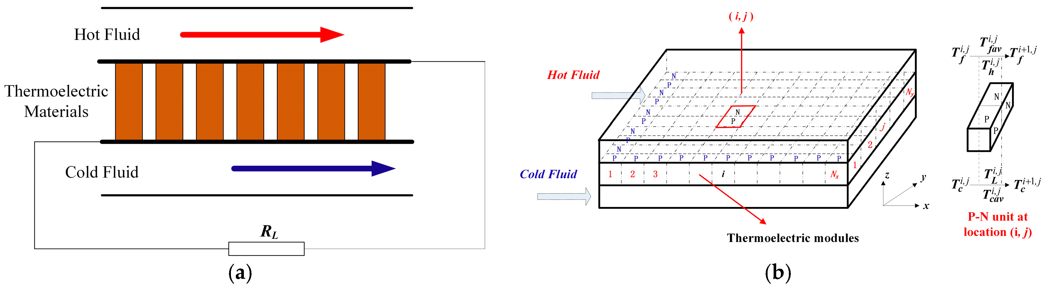
According to the different flow directions of the hot and cold fluid, there are two typical modes exist in the TEG system, namely, parallel flow mode and counter flow mode. These two modes are completely symmetrical in structure and perform under the same mechanism. Thus, only a parallel flow heat exchanger, namely, flow directions of exhaust and coolant are the same, is adopted for the TEG system in this study. The schematic of the TEG system is presented in Figure 1a, and the mathematical model for the TEG system is shown in Figure 1b. All the TEMs are divided into nx × ny computation units, and each unit is a P-N junction. The direction of fluid is defined as x direction, and along this direction there are nx rows, which are marked by i (i = 1, 2, …, nx). Similarly, the perpendicular direction is defined as y, and there are ny columns that are marked by j (i = 1, 2, …, ny). A coordinate plane is formed based on the row and column number and the coordinate of computing unit can be represented as (i, j).
A P-N junction marked (i, j) along the y direction is chosen for calculation. The inlet temperature of exhaust gas is and the outlet temperature is . The inlet temperature of coolant (Cu-EG nanofluid or EG-W) is and the outlet temperature is . Due to the small cross-sectional area of a junction, the average value of the inlet temperature and outlet temperature is used to represent fluid (exhaust gas/coolant) temperature in this junction, namely, and . Temperature of the hot side and cold side is and , and heat flux across the hot side and cold side is and , respectively. It should be pointed out that the outlet temperature of fluid in the former junction is equal to the inlet temperature of fluid in the latter junction. Apparently, along the y direction, all the P-N junctions in the same column have identical temperature distribution. Thus, each column along the y direction is considered as a computing unit.
TEMs convert the waste heat of exhaust into electricity, and the power output depends on the circuit current. According to the thermodynamic equilibrium theory, considering Joule effect, Peltier effect, and heat conduction loss of TEMs, governing equations of heat transfer process are as follows [23,24]:
In Equations (1) and (2), three terms on the right side represent Joule effect, Peltier effect, and heat conduction loss, respectively. is Seebeck coefficient of a P-N junction, is the thermal resistance of a P-N junction, and is electrical resistance of a P-N junction. These three parameters can be calculated as follows:
Because the thermal resistance of the heat exchanger is omitted, heat flux across the hot side and cold side of TEMs can be described by Newton’s cooling law as Formula (6) and (7), in which A denotes the cross section area of a P-N junction and and are heat transfer coefficient across the hot side and cold side of TEMs.
From the perspective of energy transport, it can be found that, due to the assumption of steady state, heat absorbed by the hot side of TEMs is equal to the heat loss of the exhaust. Likewise, heat loss of the cold side of TEMs is equal to the heat absorbed by the coolant. These relationships can be written as follows:
All the P-N junctions in the system are in series. Thus, current in each junction is identical to the total circuit current. Along the y direction, the total output voltage provided by junctions in a column is calculated as follows:
The total open voltage for the system can be calculated as follow:
Total resistance in the circuit is,
As a consequence, circuit current can be calculated as follows according to Ohm’s Law:
In order to solve the governing equations, initial and boundary conditions should be prescribed. In this study, the initial inlet temperatures of exhaust and coolant (Cu-EG nanofluid or EG-W) are known, and boundary conditions are given as follows:
Note that in Formulas (6) and (7), the heat transfer coefficients across the hot side and cold side of TEMs, namely, and should be prescribed. In this study, an empirical value 80 W m2 K−1 is given for [24]. The heat transfer coefficient between cold side of TEMs and coolants (Cu-EG nanofluid and EG-W) can be calculated according to following the heat transfer correlations proposed for Cu-EG nanofluid in laminar and turbulent conditions [25]:
in which denotes the Nusselt number of nanofluid, heat transfer coefficient can be calculated through the formula , denotes the Peclet number of nanoparticle , Reynolds number of nanofluid and Prandtl number of nanofluid , thermal diffusivity of nanofluid . Thermophysical properties of nanofluid are defined as follows [26,27]:
As can be seen in Equation (13), the current I was determined by the whole temperature distribution on the TEG system. Meanwhile, the temperature distribution was also affected by the current I. As can be seen in Equations (1) and (2), the current I, cold side temperature of TEMs and hot side temperature of TEMs coexist. Therefore, there is a coupled relationship between the temperature and the electric field. Since the temperature distribution of TEMs coupled with the circuit current, the iterative method presented in Figure 2 is applied to solve the governing equations, at the beginning, the number of rows along x direction nx and number of columns along y direction ny are prescribed. Then, initial current value I0 is given to solve the temperature distribution of the TEG system. According to the calculated temperature field, a new current I can be obtained and this new current I will be compared with the initial current I0. If these two value are not consistent, the new current I is set as the initial current I0 for the iterative calculation until the two values are consistent.
Power output and thermoelectric conversion efficiency are the two most important parameters to evaluate the performance of a thermoelectric-based waste heat recovery system. Thermoelectric conversion efficiency is defined as the ratio of total power output and heat absorbed from exhaust. These two parameters can be calculated by following formulas:
3. Results and Discussion
3.1. Comparison between Cu-EG Nanofluid and EG-W
In this section, the performance of the TEG system is investigated between Cu-EG nanofluid with volume fraction of 3% and EG-W. The inlet temperature of exhaust is set to 500 K, 530 K, 560 K, 590 K, 620 K, 650 K, 680 K, and 710 K, respectively. The mass flow rate of coolant is set to a constant of 0.03 kg/s. Basic computational parameters of fluids used in the iteration are listed in Table 2.
Hot side and cold side temperature distributions of TEMs for two coolants (Cu-EG nanofluid and EG-W) are obtained under different inlet temperatures of exhaust (). Along the fluid direction, temperature distributions of TEMs for the case of = 500 K, 590 K, and 710 K are presented in Figure 3a–c, respectively. As indicated in the figures, the hot side temperature of the TEMs naturally decreases slowly for both coolants, due to the heat transfer process between exhaust and hot side of the TEMs. Likewise, cold side temperature of the TEMs increases gently.
Comparison between Cu-EG nanofluid and EG-W is under the same mass flow rate. As indicated in Figure 3a–c, there are lower hot side temperature (Hot for Nano) and cold side temperature (Cold for Nano) of TEMs when Cu-EG nanofluid is adopted as the coolant. Because the heat transfer coefficient is larger than that of EG-W, it causes lower cold side temperature of TEMs than that of EG-W compared to EG-W. Moreover, although hot side temperature of TEMs also drops to some extent, the decrease of hot side temperature is smaller than the decrease of cold side temperature. Compared to EG-W, the final temperature difference is expanded when the Cu-EG is used as coolant. As can be seen in Figure 3a–c, along the x direction, the drop of cold side temperature is 4~8 K larger than the drop of hot side temperature with Cu-EG nanofluid coolant, which means the temperature difference between the hot and cold side of TEMs using Cu-EG nanofluid as coolant is 4–8 K higher than those using EG-W coolant. As mentioned in the Introduction, maximizing the temperature gradient across thermoelectric modules is an effective method to improve power output and conversion efficiency for the TEG system. Therefore, Cu-EG nanofluid as coolant would have a positive influence on the performance of TEG system.
Figure 4a,b show variations of power output and conversion efficiency with inlet temperature of exhaust under the concentration of 3% Cu-EG nanofluid and EG-W. As presented in Figure 4a, for both coolants, power output keeps increasing as the inlet temperature of exhaust increases, since increasing inlet temperature of exhaust increases heat transferred to the hot side of TEMs. Then, temperature difference across thermoelectric modules would rise when the cooling condition is fixed. Meanwhile, it clearly shows that Cu-EG nanofluid as coolant gains a larger power output than EG-W over the full temperature range. Under the same mass flow rate, the increase of power output for Cu-EG nanofluid is 2.5–8 W larger (12.65–13.95%) compared to EG-W. The conversion efficiency increases with the rise of exhaust temperature under both kinds of coolants, which is similar to the trend of power output, as presented in Figure 4b. Thus, we can conclude that Cu-EG nanofluid at a certain concentration as coolant can improve output performance of TEG system to some extent.
3.2. Comparison between Different Cu-EG Nanofluid Concentrations
Comparisons in Section 3.1 are based on the Cu-EG nanofuid with 3% concentration. For the sake of choosing optimum concentration of nanofluid, it is necessary to clarify the effects of different concentrations on the output performance of the TEG system. Therefore, in this section, the effect of nanofluid concentration on the performance of the system will be discussed in detail. Likewise, the mass flow rate of Cu-EG nanofluid coolant is equal for all cases. Computational parameters of Cu-EG nanofluid under different concentrations are listed in Table 3.
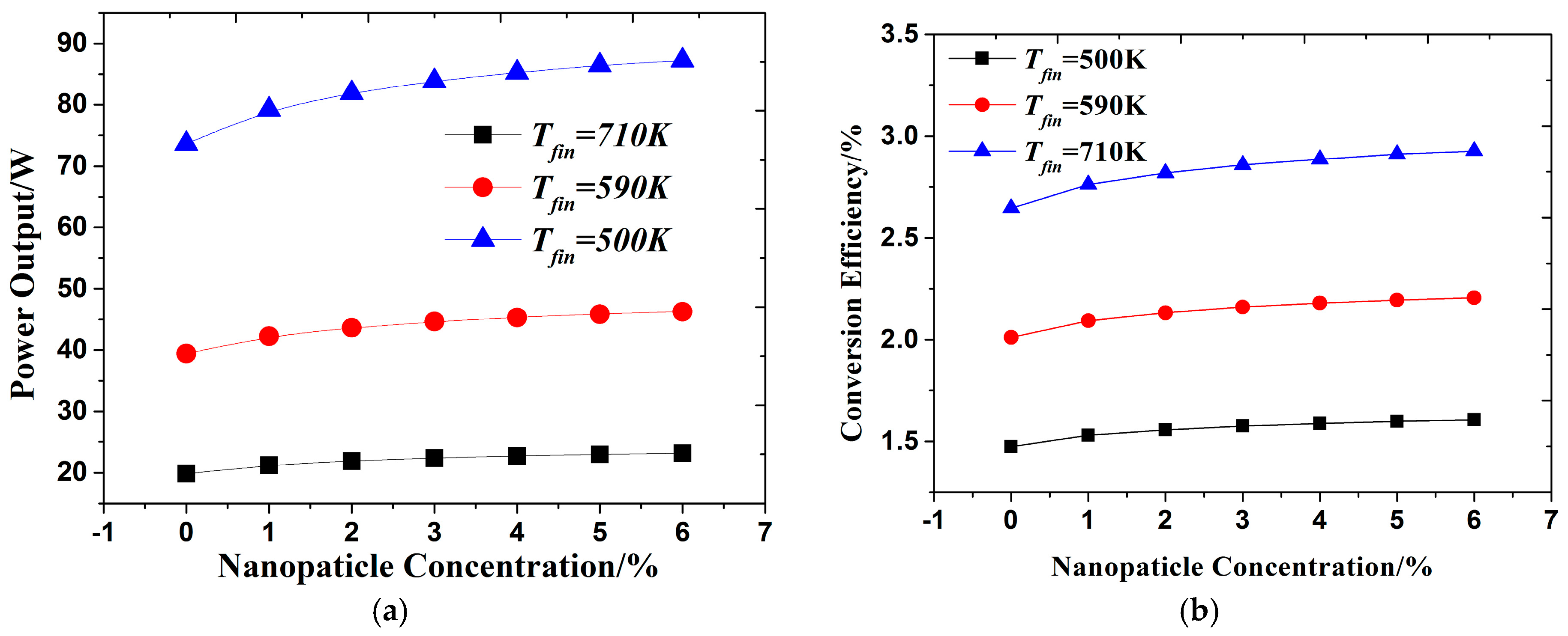
Figure 5a,b show power output and conversion efficiency varies with concentration of Cu-EG nanofluid under different exhaust inlet temperatures. Within the figures, power output and conversion efficiency under EG-W cooling condition is also plotted for comparison. It can be found that power outputs and conversion efficiency under different concentrations of Cu-EG nanofluid are higher than that of EG-W at a fixed inlet temperature of exhaust, and the bigger the concentration of nanofluid is, the higher the power output and conversion efficiency will be. The reason is that Cu-EG has larger heat transfer coefficient than EG-W, leading to a bigger temperature difference between the cold side and hot side of the TEMs and then higher power output and thermoelectric conversion efficiency. The higher the concentration of nanofluid is, the better heat transfer performance the coolant will achieve, so the output performance increases with the rise of nanofluid concentration. It should be mentioned that the concentration of nanofluid always has an upper limit considering the stability of nanofluid. Thus, the concentration of Cu-EG nanofluid discussed in this study is less than 6%. Through the comparison within Figure 5a, we can find that the variation trends of power output under different exhaust inlet temperatures are almost the same. The difference is only the value of power output, which enhances dramatically with the increase of exhaust inlet temperature when the concentration of the nanofluid is fixed. This is because the increase of inlet temperature of the exhaust will increase the heat transferred to hot side of the TEMs and will result in a larger power output as mentioned, in Section 3.1. From the analysis in this section, the conclusion can made that increasing concentration of Cu-EG nanofluid within a realizable range has a positive effect on the output performance of the TEG system.
3.3. Analysis of Total Area of TEMs
The total area of the TEMs is an important parameter for the TEG system. On the one hand, total area is related to internal resistance, which will affect circuit current and the output performance of the system. On the other hand, it also has an influence on the hot and cold side temperature distributions of the TEMs, which has significant effect on the output performance of the system as already discussed in the above sections. In order to elucidate the effect of the total area of the TEMs on the output performance of the system, the relation between power output and total area of TEMs is studied under various inlet temperatures of exhaust in this section. The mass flow rate of exhaust is fixed at 0.02 kg/s, and mass flow rates of Cu-EG nanofluid and EG-W coolant are the same.
Figure 6a,b describes power output variations with total area of TEMs for Cu-EG nanofluid and EG-W cooling conditions, respectively. It can be obviously seen from Figure 6a,b that power output rises significantly at first and then drops slightly as increasing total area of TEMs for both cooling conditions under different inlet temperatures of exhaust, indicating that optimal total area of TEMs exists for maximizing output performance of the TEG system. It is interesting to note that the optimal total area of the TEMs is independent of the inlet temperature of exhaust for both cooling conditions. As can be seen from the figures, the optimal total area of TEMs is 0.5063 m2 for EG-W cooling condition and 0.4375 m2 for Cu-EG nanofluid cooling condition with concentration of 3%. This is because the variation trends of temperature difference across thermoelectric modules are almost the same under different exhaust inlet temperatures. Therefore, the variation trends of power output under different exhaust inlet temperatures are almost the same, and the difference is only the value of power output, as already mentioned in Section 3.2. In considering the independency with inlet temperature of exhaust, this feature will have significant meaning for heat recovery from engine exhaust with fluctuating characteristics.
Through the comparison between Figure 6a,b, we can find that the optimal area of Cu-EG nanofluid cooling condition is 0.0688 m2 (13.6%) smaller than that of EG-W cooling condition. Due to the higher heat transfer coefficient provided by Cu-EG nanofluid coolant, TEMs with Cu-EG nanofluid coolant can keep recovering more waste energy along the x direction than the EG-W cooling condition. Meanwhile, waste energy of the exhaust is constant since state parameters of the exhaust gas are prescribed in normal conditions. Thus, the optimal value of the TEMs area gets smaller compared with the EG-W cooling condition. This will bring lots of advantages for the TEMs arrangement strategy within TEG system. When the arrangement space of the TEMs for the system is sufficient, both coolants can make the system obtain peak power output, but in this situation, the system can get higher peak power output with fewer TEMs using Cu-EG nanofluid as coolant, saving thermoelectric materials and cost. When the arrangement space of the TEMs is insufficient, power output for the system only can be up to as large as possible under both cooling conditions. However, using Cu-EG nanofluid as a coolant can make system realize larger power output with the same number of TEMs. In summary, Cu-EG nanofluid as coolant can decrease optimal total area of TEMs compared with EG-Water, which will bring significant advantages for the optimization and arrangement of TEMs whether system space is sufficient or not.
3.4. Effect of Hot Side Heat Transfer Coefficient of TEMs
Enhancing the heat transfer process between the hot side of the TEMs and the exhaust is also an effective method to maximize the temperature gradient across its embedded thermoelectric modules. A high porosity open-cell metal foam heat exchanger is a practical way to enhance heat transfer between high temperature exhaust and hot side of TEMs, which can increase the heat transfer coefficient of air flow from 20–100 W m2 K−1 to several hundred [28,29]. Hence, it is necessary to investigate the effect of hot side heat transfer coefficient of TEMs on output performance of the TEG system when using Cu-EG nanofluid as coolant at the cold side of TEMs.
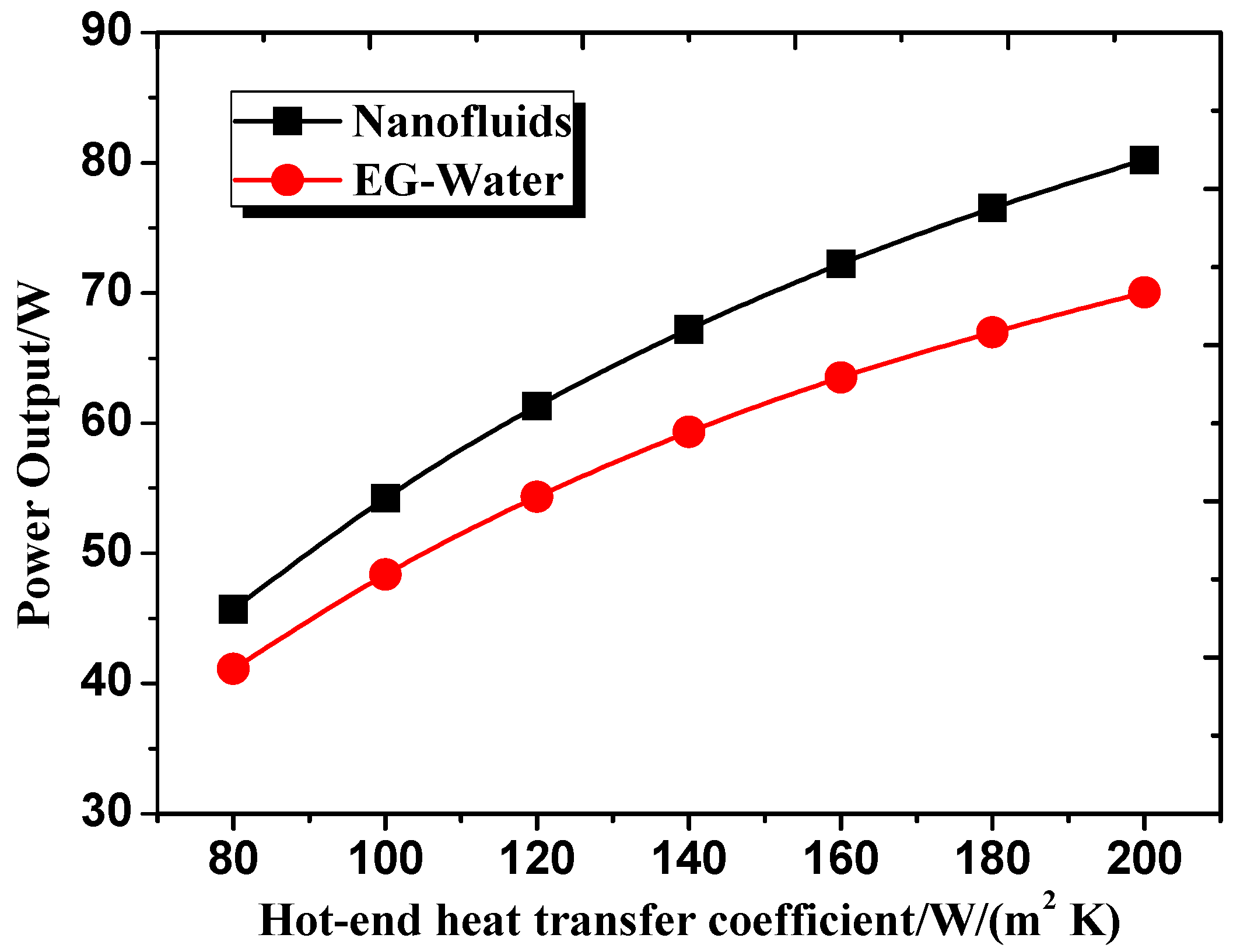
In this section, all discussions are based on the following conditions: the concentration of Cu-EG nanofluid is 3%, the mass flow rate of exhaust is 0.02 kg/s, and the inlet temperature of exhaust is 620 K. Power output variation with hot side heat transfer coefficient of TEMs is presented in Figure 7 when using Cu-EG nanofluid and EG-W as coolants for cold side of TEMs. As can be seen from Figure 7, power output increases as hot side heat transfer coefficient of TEMs increases, and power output under Cu-EG nanofluid coolant is larger than that of EG-W coolant. Moreover, the power output difference between Cu-EG nanofluid and EG-W coolant keeps increasing with the increase of hot side heat transfer coefficient of the TEMs. When hot side heat transfer coefficient is 80 W m2 K−1, power output enhancement is 4.6 W (11.2%). When hot side heat transfer coefficient rises to 200 W m2 K−1, power output enhancement rises to 11.2 W (14.6%). This can be explained as follows: due to higher heat transfer coefficient of hot side of TEMs, more heat is transferred to hot side of TEMs, resulting in a higher hot side temperature. Meanwhile, using Cu-EG nanofluid as coolant for cold side of the TEMs reduces cold side temperature of the TEMs. The higher heat transfer coefficient of hot side is, the larger temperature difference between hot and cold side of the TEMs. Therefore, power output enhancement under Cu-EG nanofluid coolant is larger than that of EG-W coolant as the increase of hot side heat transfer coefficient of the TEMs. From the perspective of synergy effect on heat transfer enhancement for hot side of the TEMs, Cu-EG nanofluid as coolant for cold side of the TEMs is also superior to EG-W coolant.
4. Conclusions
The present study investigates performance of thermoelectric based automotive waste heat recovery system with nanofluid coolant. Power output and thermoelectric conversion efficiency of the TEG system are compared between two coolants: Cu-EG nanofluid and EG-W. Moreover, key factors for system output performance, such as inlet temperature of exhaust gas, concentration of nanofluid, and total area of TEMs, are comparatively analyzed. Key findings of the present study are as follows:
- (1)
- Compared to conventional EG-W coolant, Cu-EG nanofluid can attain a lower cold side temperature of TEMs and a larger temperature difference between hot and cold end of TEMs under equal mass flow rate, which will effectively improve power output and thermoelectric conversion efficiency for the TEG system;
- (2)
- Cu-EG nanofluid as coolant can decrease the optimal total area of TEMs and increase the power output compared with EG-W coolant under equal mass flow rate. This finding will bring significant advantages for the optimization and arrangement of TEMs in the system. When the arrangement space of TEMs for the system is sufficient, less TEMs are required when using Cu-EG nanofluid as coolant, which will save thermoelectric materials and the cost. When the arrangement space of TEMs is limited, Cu-EG nanofluid as coolant can make system output more power compared to EG-W coolant under the same amount of TEMs;
- (3)
- Power output enhancement under Cu-EG nanofluid coolant is larger than that of EG-W coolant as the increase of hot side heat transfer coefficient of TEMs. From the perspective of synergy effect on heat transfer enhancement for the hot side of the TEMs, Cu-EG nanofluid as coolant for the cold side of the TEMs is also superior to EG-W coolant.
Acknowledgments
This study was supported by the Science and Technology Partnership Program, Ministry of Science and Technology of China (KY201401003).
Author Contributions
Zhi Li and Zhen Chen conceived and performed the numerical experiments; Wenhao Li analyzed the data and wrote the paper.
Conflicts of Interest
The authors declare no conflict of interest.
Nomenclature
| Nomenclature | |
| Specific heat of exhaust (kJ kg−1 K−1) | |
| Specific heat of coolant (kJ kg−1 K−1) | |
| Diameter of tube (m) | |
| dp | Diameter of nanoparticle (mm) |
| h | Height of TEM leg (mm) |
| Heat transfer coefficient of hot side (W m−2 K−1) | |
| Heat transfer coefficient of cold side (W m−2 K−1) | |
| i | Direction of x coordinate |
| j | Direction of y coordinate |
| Thermal conductivity of basic fluid (W m−1 K−1) | |
| Thermal conductivity of nanoparticle (W m−1 K−1) | |
| Thermal conductivity of nanofluid (kJ m−3 K−1) | |
| l | Length of TEM leg (mm) |
| Mass flow rate of exhaust (kg/s) | |
| Mass flow rate of coolant (kg/s) | |
| Number of TE modules in x direction | |
| Number of TE modules in y direction | |
| Heat flow density for hot side (W/m2) | |
| Heat flow density for cold side (W/m2) | |
| Resistance for a P-N junction (Ω) | |
| Electrical load resistance (Ω) | |
| Temperature of cold fluid (K) | |
| Temperature of exhaust (K) | |
| Hot side temperature of TEM (K) | |
| Cold side temperature of TEM (K) | |
| Average speed of nanofluid (m/s) | |
| w | Width of TEM leg (mm) |
| Greek Symbols | |
| Seebeck coefficient of N-type material (V/K) | |
| Thermal diffusivity coefficient of nanofluid (m2/s) | |
| Seebeck coefficient of P-type material (V/K) | |
| Thermal conductivity of P-type material (W m−1 K−1) | |
| Thermal conductivity of N-type material (W m−1 K−1) | |
| Density of nanoparticle (kg/m3) | |
| Density of nanofluid (kg/m3) | |
| Density of base fluid (kg/m3) | |
| Resistivity of P-type material (Ω·m) | |
| Product of density and specific heat capacity for base fluid (kJ m−3 K−1) | |
| Product of density and specific heat capacity for nanoparticle (kJ m−3 K−1) | |
| Product of density and specific heat capacity for nanofluid (kJ m−3 K−1) | |
| Kinematic viscosity of nanofluid (m2/s) | |
| Dynamic viscosity of basic fluid (Pa s) | |
| φ | Concentration of nanofluid |
References
- Liang, X.; Sun, X.; Tian, H.; Shu, G.; Wang, Y.; Wang, X. Comparison and parameter optimization of a two-stage thermoelectric generator using high temperature exhaust of internal combustion engine. Appl. Energy 2014, 130, 190–199. [Google Scholar] [CrossRef]
- Talbi, M.; Agnew, B. Energy recovery from diesel engine exhaust gases for performance and air conditioning. Appl. Therm. Eng. 2002, 22, 693–702. [Google Scholar] [CrossRef]
- Zhang, H.G.; Wang, E.H.; Fan, B.Y. A performance analysis of a novel system of a dual loop bottoming organic Rankine cycle (ORC) with a light-duty diesel engine. Appl. Energy 2013, 102, 1504–1513. [Google Scholar] [CrossRef]
- Vazquez, J.; Sanz-Bobi, M.; Palacios, R.; Arenas, A. State of the art of thermoelectric generators based on heat recovered from the exhaust of automobiles. In Proceedings of the Seventh European Workshop on Thermoelectric, Pamplona, Spain, 3–4 October 2002. [Google Scholar]
- Liang, X.; Sun, X.; Shu, G.; Sun, K.; Wang, X.; Wang, X. Using the analytic network process (ANP) to determine method of waste energy recovery from engine. Energy Convers. Manag. 2013, 66, 304–311. [Google Scholar] [CrossRef]
- Gewald, D.; Karellas, S.; Schuster, A.; Spliethoff, H. Integrated system approach for increase of engine combined cycle efficiency. Energy Convers Manag. 2012, 60, 32–44. [Google Scholar] [CrossRef]
- Stevens, R.J.; Weinstein, S.J.; Koppula, K.S. Theoretical limits of thermoelectric power generation from exhaust gases. Appl. Energy 2014, 133, 80–88. [Google Scholar] [CrossRef]
- Liu, X.; Deng, Y.D.; Li, Z.; Su, C.Q. Performance analysis of a waste heat recovery thermoelectric generation system for automotive application. Energy Convers. Manag. 2015, 90, 121–127. [Google Scholar] [CrossRef]
- Haidar, J.G.; Ghogel, J.I. Waste heat recovery from the exhaust of low-power diesel engine using thermal electric generators. In Proceedings of the 20th International Conference on Thermoelectrics (ICT2001), Beijing, China, 8–11 June 2001. [Google Scholar]
- Biswas, K.; He, J.Q.; Blum, I.D.; Wu, C.I.; Hogan, T.P.; Seidman, D.N.; Nan, C.-W. High-performance bulk thermoelectrics with all-scale hierarchical architectures. Nature 2012, 489, 414–418. [Google Scholar] [CrossRef] [PubMed]
- Butt, S.; Ren, Y.Y.; Farooq, M.Y.; Zhan, B.; Sagar, R.U.R.; Lin, Y.H.; Nan, C.W. Enhanced thermoelectric performance of heavy-metals (M: Ba, Pb) doped misfit-layered ceramics: (Ca2−xMxCoO3)0.62(CoO2). Energy Convers. Manag. 2014, 83, 35–41. [Google Scholar] [CrossRef]
- Zhao, L.D.; Lo, S.H.; Zhang, Y.S.; Sun, H.; Tan, G.J.; Uher, C.; Wolverton, C.; Dravid, V.P.; Kanatzidis, M.G. Ultralow thermal conductivity and high thermoelectric figure of merit in SnSe crystals. Nature 2014, 508, 373–377. [Google Scholar] [CrossRef] [PubMed]
- Kim, S.I.; Lee, K.H.; Mun, H.A.; Kim, H.S.; Hwang, S.W.; Roh, J.W.; Yang, D.J.; Shin, W.H.; Li, X.S.; Lee, Y.H.; et al. Dense dislocation arrays embedded in grain boundaries for high-performance bulk thermoelectrics. Science 2015, 348, 109–114. [Google Scholar] [CrossRef] [PubMed]
- Sahin, A.; Yilbas, B.S. The thermoelement as thermoelectric power generator: Effect of leg geometry on the efficiency and power generation. Energy Convers. Manag. 2013, 65, 26–32. [Google Scholar] [CrossRef]
- Niu, Z.; Diao, H.; Yu, S.; Jiao, K.; Du, Q.; Shu, G. Investigation and design optimization of exhaust-based thermoelectric generator system for internal combustion engine. Energy Convers. Manag. 2014, 85, 85–101. [Google Scholar] [CrossRef]
- Belanger, S.; Gosselin, L. Thermoelectric generator sandwiched in a crossflow heat exchanger with optimal connectivity between modules. Energy Convers. Manag. 2011, 552, 2911–2918. [Google Scholar] [CrossRef]
- Wang, T.; Luan, W.; Wang, W.; Tu, S.-T. Waste heat recovery through plate heat exchanger based thermoelectric generator system. Appl. Energy 2014, 136, 860–865. [Google Scholar] [CrossRef]
- Wang, Y.; Dai, C.; Wang, S. Theoretical analysis of a thermoelectric generator using exhaust gas of vehicles as heat source. Appl. Energy 2013, 112, 1171–1180. [Google Scholar] [CrossRef]
- Choi, S.U.S.; Eastman, J.A. Enhancing thermal conductivity of fluids with nanoparticles. In Developments and Applications of Non-Newtonian Flow, Proceedings of the ASME International Mechanical Engineering Congress and Exhibition, San Francisco, CA, USA, 12–17 November 1995; Siginer, D.A., Wang, H.P., Eds.; American Society of Mechanical Engineers: New York, NY, USA, 1995. [Google Scholar]
- Tzeng, S.C.; Lin, C.W.; Huang, K.D. Heat transfer enhancement of nanofluids in rotary blade coupling of four-wheel-drive vehicles. Acta Mech. 2005, 179, 11–23. [Google Scholar] [CrossRef]
- Kulkarni, D.P.; Vajjha, R.S.; Das, D.K.; Oliva, D. Application of aluminum oxide nanofluids in diesel electric generator as jacket water coolant. Appl. Therm. Eng. 2008, 28, 1774–1781. [Google Scholar] [CrossRef]
- Peyghambarzadeh, S.M.; Hashemabadi, S.H.; Hoseini, S.M.; Jamnani, M.S. Experimental study of heat transfer enhancement using water/ethylene glycol based nanofluids as a new coolant for car radiators. Int. Commun. Heat Mass Transf. 2011, 38, 1283–1290. [Google Scholar] [CrossRef]
- He, W.; Wang, S.X.; Zhang, X.; Li, Y.Z.; Lu, C. Optimization design method of thermoelectric generator based on exhaust gas parameters for recovery of engine waste heat. Energy 2015, 91, 1–9. [Google Scholar] [CrossRef]
- He, W.; Wang, S.X.; Lu, C.; Zhang, X.; Li, Y.Z. Influence of different cooling methods on thermoelectric performance of an engine exhaust gas waste heat recovery system. Appl. Energy 2016, 162, 1251–1258. [Google Scholar] [CrossRef]
- Xuan, Y.; Li, Q. Investigation on convective heat transfer and flow features of nanofluids. J. Heat Transf. Trans. ASME 2003, 125, 151–155. [Google Scholar] [CrossRef]
- Xuan, Y.; Roetzel, W. Conceptions of heat transfer correlation of nanofluids. Int. J. Heat Mass Transf. 2000, 43, 3701–3707. [Google Scholar] [CrossRef]
- Pak, B.C.; Cho, Y.I. Hydrodynamic and heat transfer study of dispersed fluids with submicron metallic oxide particles. Exp. Heat Transf. 1998, 11, 151–170. [Google Scholar] [CrossRef]
- Mancin, S.; Zilio, C.; Diani, A.; Rossetto, L. Air forced convection through metal foams: Experimental results and modeling. Int. J. Heat Mass Transf. 2013, 62, 112–123. [Google Scholar] [CrossRef]
- Mancin, S.; Zilio, C.; Diani, A.; Rossetto, L. Experimental air heat transfer and pressure drop through copper foams. Exp. Therm. Fluid Sci. 2012, 36, 224–232. [Google Scholar] [CrossRef]
Figure 1.
(a) Schematic of the thermoelectric generator (TEG) system; (b) mathematical model for the TEG system.
Figure 1.
(a) Schematic of the thermoelectric generator (TEG) system; (b) mathematical model for the TEG system.

Figure 2.
Flow chart of iterative calculation.
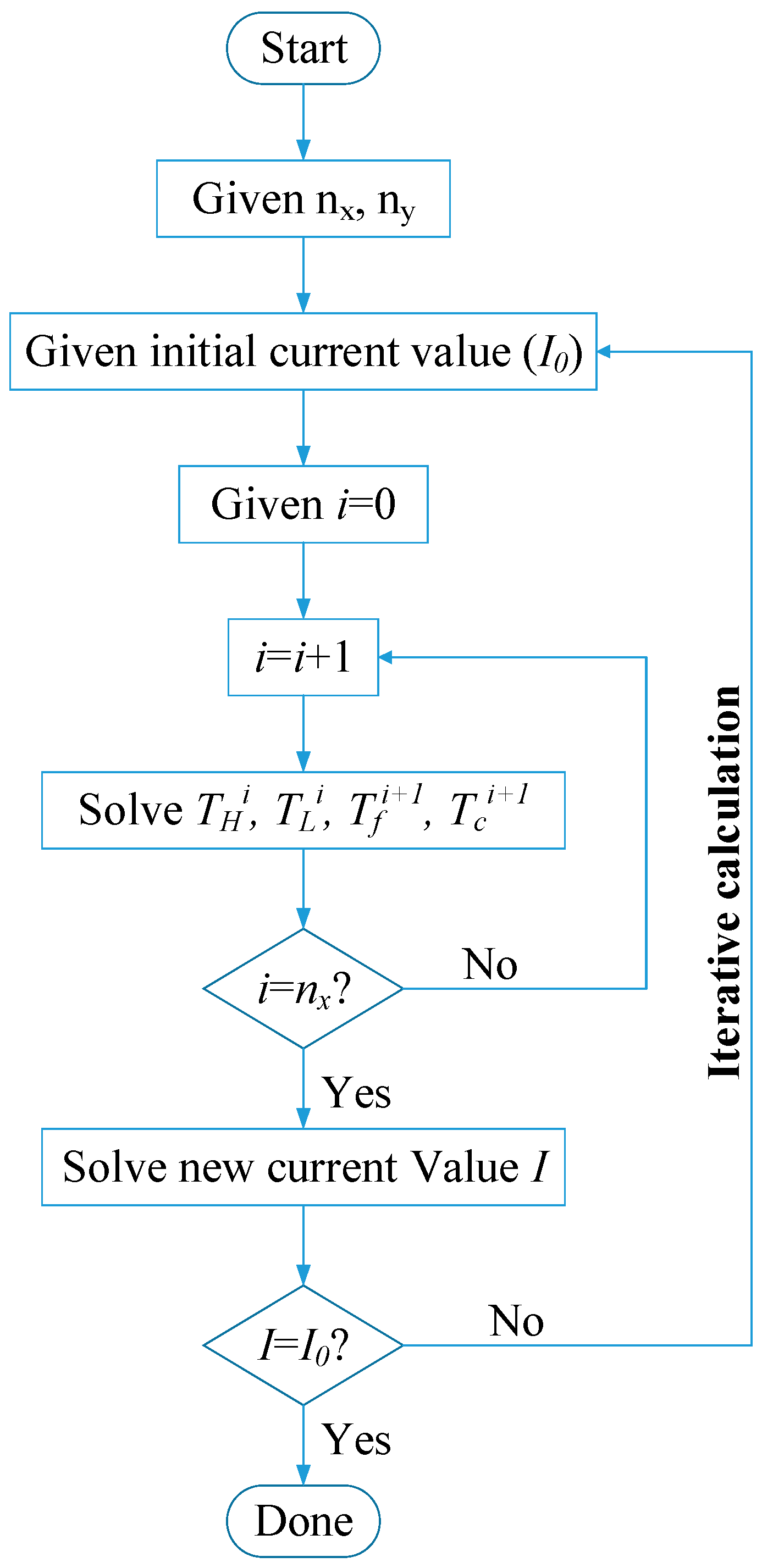
Figure 3.
Temperature distributions of thermoelectric modules (TEMs) for two coolants under different inlet temperatures of exhaust: (a) Tfin = 500 K; (b) Tfin = 590 K; (c) Tfin = 720 K.
Figure 3.
Temperature distributions of thermoelectric modules (TEMs) for two coolants under different inlet temperatures of exhaust: (a) Tfin = 500 K; (b) Tfin = 590 K; (c) Tfin = 720 K.
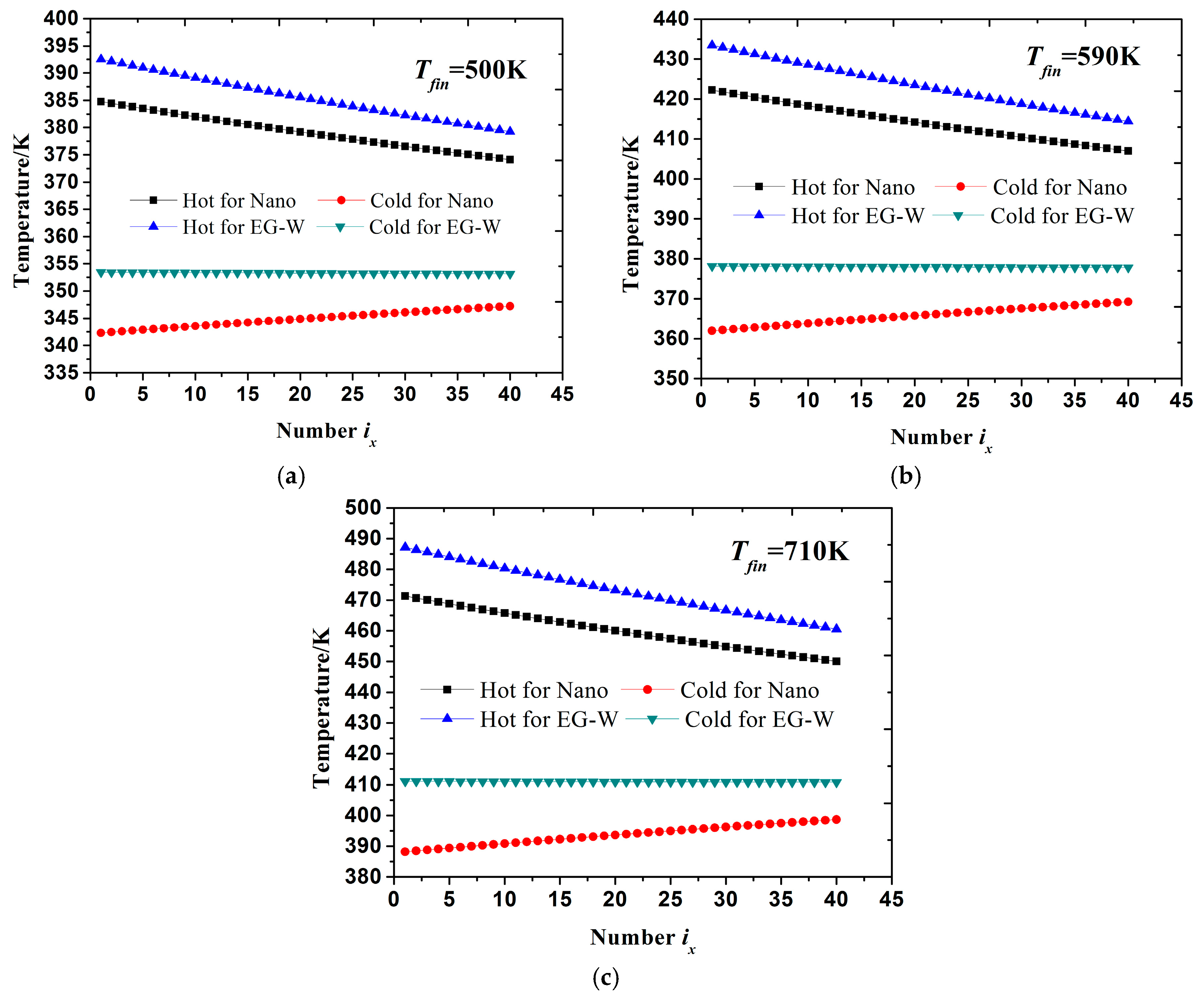
Figure 4.
Variations of power output and conversion efficiency with inlet temperature of exhaust under two coolants: (a) Power output; (b) Conversion efficiency.
Figure 4.
Variations of power output and conversion efficiency with inlet temperature of exhaust under two coolants: (a) Power output; (b) Conversion efficiency.

Figure 5.
Variations of power output and conversion efficiency with Cu-EG nanofluid concentration under different exhaust inlet temperatures: (a) Power output; (b) Conversion efficiency.
Figure 5.
Variations of power output and conversion efficiency with Cu-EG nanofluid concentration under different exhaust inlet temperatures: (a) Power output; (b) Conversion efficiency.

Figure 6.
Power output variations with total area of TEMs for Cu-EG nanofluid and EG-W coolant: (a) EG-W coolant; (b) Cu-EG nanofluid coolant.
Figure 6.
Power output variations with total area of TEMs for Cu-EG nanofluid and EG-W coolant: (a) EG-W coolant; (b) Cu-EG nanofluid coolant.
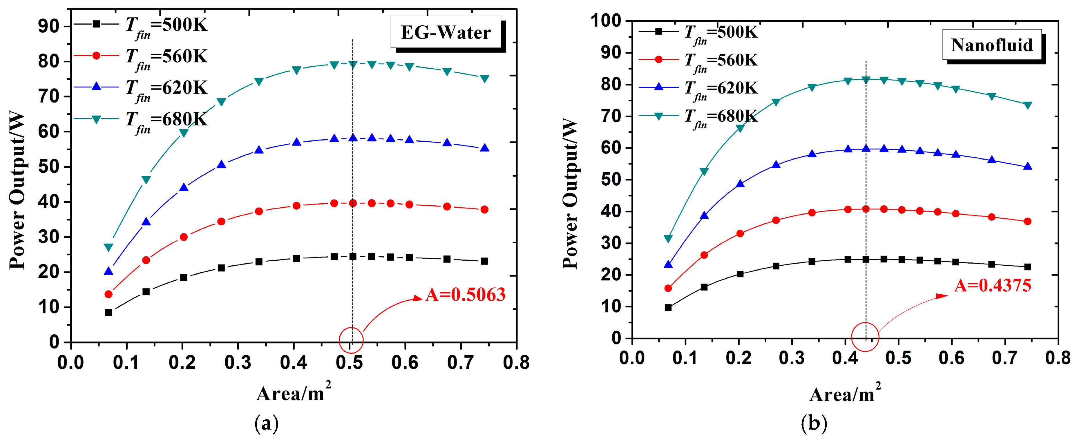
Figure 7.
Power output varies with hot side heat transfer coefficient of the TEMs under Cu-EG nanofluid and EG-W as coolants for the cold side of the TEMs.
Figure 7.
Power output varies with hot side heat transfer coefficient of the TEMs under Cu-EG nanofluid and EG-W as coolants for the cold side of the TEMs.


Table 1.
Basic calculation parameters of thermoelectric material.
| Semiconductor Parameters | Value |
|---|---|
| Seebeck coefficient of P-type leg | 2.037 × 10⁻⁴ V K−1 |
| Seebeck coefficient of N-type leg | −1.721 × 10⁻⁴ V K−1 |
| Resistivity of P-type leg | 1.314 × 10⁻⁵ Ω m |
| Resistivity of N-type leg | 1.119 × 10⁻⁵ Ω m |
| Thermal conductivity of P-type leg | 1.265 W m−1 K−1 |
| Thermal conductivity of N-type leg | 1.011 W m−1 K−1 |
| Length of P- and N-type leg | 5 mm |
| Width of P- and N-type leg | 5 mm |
| Height of P- and N-type leg | 5 mm |
Table 2.
Basic computational parameters of fluid.
| Parameters | Value |
|---|---|
| Inlet temperature of cold fluid | 298 K |
| Specific heat capacity of Cu-EG nanofluid | 2775 J kg−1 K−1 |
| Specific heat capacity of EG-W | 3400 J kg−1 K−1 |
| Specific heat capacity of exhaust gas | 1020 J kg−1 K−1 |
| Heat transfer coefficient of Cu-EG nanofluid | 204 W m−2 K−1 |
| Heat transfer coefficient of EG-W | 152 W m−2 K−1 |
| Heat transfer coefficient of exhaust gas | 80 W m−2 K−1 |
| Mass flow rate of exhaust gas | 0.03 kg s−1 |
| Mass flow rate of cold fluid | 0.03 kg s−1 |
Table 3.
Computational parameters of Cu-Ethylene glycol (Cu-EG) nanofluid under different concentrations.
Table 3.
Computational parameters of Cu-Ethylene glycol (Cu-EG) nanofluid under different concentrations.
| Concentration φ | Heat Transfer Coefficient (W·m−2·K−1) | Specific Heat Capacity (J·kg−1·K−1) | Density (kg·m−3) | Thermal Diffusivity (m2·s−1) | Dynamic Viscosity (Pa·s) |
|---|---|---|---|---|---|
| 1% | 176 | 3160 | 1136 | 1.15 × 10⁻⁷ | 0.00183 |
| 2% | 191 | 2955 | 1215 | 1.19 × 10⁻⁷ | 0.00187 |
| 3% | 204 | 2775 | 1293 | 1.22 × 10⁻⁷ | 0.00192 |
| 4% | 215 | 2615 | 1371 | 1.26 × 10⁻⁷ | 0.00197 |
| 5% | 225 | 2473 | 1450 | 1.30 × 10⁻⁷ | 0.00202 |
| 6% | 234 | 2346 | 1528 | 1.34 × 10⁻⁷ | 0.00208 |
© 2017 by the authors. Licensee MDPI, Basel, Switzerland. This article is an open access article distributed under the terms and conditions of the Creative Commons Attribution (CC BY) license (http://creativecommons.org/licenses/by/4.0/).
Share and Cite
MDPI and ACS Style
Li, Z.; Li, W.; Chen, Z. Performance Analysis of Thermoelectric Based Automotive Waste Heat Recovery System with Nanofluid Coolant. Energies 2017, 10, 1489. https://doi.org/10.3390/en10101489
AMA Style
Li Z, Li W, Chen Z. Performance Analysis of Thermoelectric Based Automotive Waste Heat Recovery System with Nanofluid Coolant. Energies. 2017; 10(10):1489. https://doi.org/10.3390/en10101489
Chicago/Turabian StyleLi, Zhi, Wenhao Li, and Zhen Chen. 2017. "Performance Analysis of Thermoelectric Based Automotive Waste Heat Recovery System with Nanofluid Coolant" Energies 10, no. 10: 1489. https://doi.org/10.3390/en10101489
Note that from the first issue of 2016, this journal uses article numbers instead of page numbers. See further details here.