Effect of Coil Configuration on Conversion Efficiency of EMAT on 7050 Aluminum Alloy

1
Research Institute of Light Alloys, Central South University, Changsha 410083, China
2
State Key Laboratory of High-Performance Complex Manufacturing, Central South University, Changsha 410083, China
3
Nonferrous Metal Oriented Advanced Structural Material and Manufacturing Cooperative Innovation Center, Central South University, Changsha 410083, China
*
Author to whom correspondence should be addressed.
Energies 2017, 10(10), 1496; https://doi.org/10.3390/en10101496
Submission received: 11 August 2017
/
Revised: 6 September 2017
/
Accepted: 20 September 2017
/
Published: 26 September 2017
Abstract
:Compared to traditional ultrasonic detection methods, the electromagnetic acoustic transducer (EMAT) technique can be applied in many hostile environments such as elevated temperatures, on-line inspections, etc. However, the EMAT technique has a low conversion efficiency. This paper develops a numerical model to study the effects of the coil configurations on the conversion efficiency of shear-wave EMAT on 7050 aluminum alloy. The numerical model is fully validated by the experiment data. The effects of the configuration parameters, including the coil wires’ cross-sectional area, coil wires’ cross-sectional shape, and distance between coil wires, on the conversion efficiency are then discussed. The results indicate that after using the coil with a square cross-section, the conversion efficiency of EMAT is increased by 22.5%. In addition, the coil wires’ cross-sectional area and the distance between coil wires also have a significant effect on the conversion efficiency.
1. Introduction
The electromagnetic acoustic transducer (EMAT) technique was developed in the early 1970s [1,2,3,4]. As a potential method of non-destructive testing and evaluation, EMAT has attracted great attention [5,6,7,8,9] due to its advantages, such as the liquid coupling and the surface preconditioning being not required, which consequently render this method useful in many areas of modern technology [10,11,12,13,14]. However, many researchers [15,16,17,18] found that EMAT has a low conversion efficiency compared to traditional acoustic transducers. In addition, 7050 aluminum alloy, a key material due to its excellent properties including low density, high special strength, and perfect resistance to corrosion, has been applied extensively in modern industries [19]. Therefore, the enhancement in the conversion efficiency of EMAT on 7050 aluminum alloy is required urgently.
Generally, there are four main influence factors on the conversion efficiency of EMAT, including magnetic circuit, electric circuit, coil, and lift-off. Pei et al. [20] presented a new magnetic circuit configuration for the enhancement of EMAT, and pointed out that the peak flux density could be increased by a factor of approximately 1.9. Isla et al. [21] established a model to investigate the impedance of the coil of EMAT, and found that the resistance of the source and the coil should be the smallest possible to maximize the eddy currents under the maximum power transfer condition. Ashigwuike et al. [22] developed a numerical model to discuss different coil structures, such as meander line coil, butterfly/linear coil, and spiral coil. Huang et al. [23] studied the relationship between the lift-off of coil and the transmitting/receiving ultrasonic signals.
In order to enhance the performance and gain a better understanding of EMAT operation, some relevant investigations have been carried out. Lee et al. [5] used numerical and experimental approaches to investigate the EMAT generating Lamb-wave mode, and presented a method to generate only symmetric omnidirectional Lamb-wave. Edwards et al. [7] designed a low-frequency and a wide-band Rayleigh surface wave EMAT on a real rail sample, and found that the depth of defect could be characterized by the study of both the time domain signal and frequency-dependent behavior. Clough et al. [16] established a system of circumferential shear horizontal guided wave EMAT for pipeline screening, and analyzed the behaviors of wave modes under the wave interaction with defects.
In summary, the improvement to the conversion efficiency of EMAT is a rather involved problem, and it is therefore not surprising that only scant information regarding the conversion efficiency problem has been reported. In this paper, a frequency domain numerical model is established to calculate the static magnetic field generated by a permanent magnet, as well as the dynamic magnetic field and eddy current at skin depth generated by the transmitting coil. The effects of different coil configurations on the conversion efficiency of shear wave EMAT on 7050 aluminum alloy are discussed.
2. Model Development
2.1. Mathematic Model
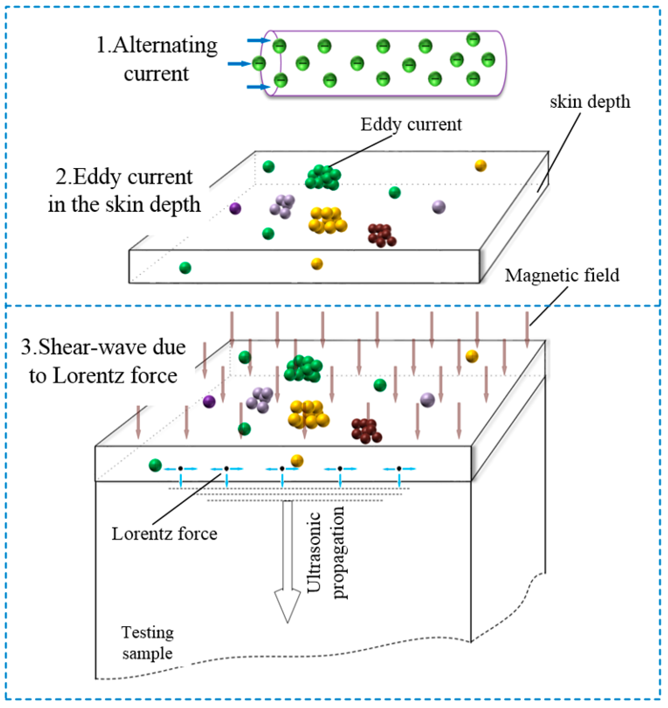
The processes of the conversion in EMAT involve the multi-physics coupling problem, and the fundamental schematic of electromagnetic-acoustic coupling is shown in Figure 1. When an alternating current travels through the coil, it will induce the alternating eddy current in the skin depth of the testing sample that is near to coil. Simultaneously, if there is an extra magnetic field, it will interact with the alternating eddy current to generate the Lorentz force, following which the vibrations of the particles in the skin depth will be activated by the Lorentz force, which consequently forms the ultrasonic wave propagating into the material.
For an EMAT system, a magnetic field generated by a permanent magnet belongs to magnetostatic problems where no electric currents are presented. Therefore, the magnetic field’s control equation can be deduced based on Maxwell’s theory [24,25]. In the region of the free currents, the electric field E is zero. The Maxwell’s equations [24] can be written in the following form:
where H is the magnetic field intensity and B is the magnetic flux density. Equations (1) and (2) imply that the magnetic scalar potential , as shown in the following, can be defined.
Additionally, if the permanent magnet belongs to the nonlinear material, the constitutive relations [26,27] can be expressed as:
By applying Equations (3) and (4) to Equation (2), the magnetic field’s control equation can be rewritten as the following:
where is the relative permeability, is the permeability of vacuum, is the remanent magnetic flux density, which is to say, the magnetic flux density when no magnetic field is present. By solving Equation (5), the modeling of a static magnetic field generated by a permanent magnet can be achieved.
In order to deduce the control equations of the dynamic magnetic field and the eddy current generated by the AC current in the coil, Maxwell-Ampère’s law [24] is adopted, as shown by the following:
where D is the electric flux density and is the current density, which includes the external current density and the internal current density, which can be expressed as:
Therefore, substituting Equation (7) into Equation (6), Maxwell-Ampère’s law can be rewritten as the following:
where is the external current density, is the electrical conductivity, and E is the electric field intensity. Generally, the magnetic vector potential A is defined to formulate the problems, which can be expressed as:
By combining the constitutive relations (10) with Equations (7)–(9), the frequency domain control equations of the dynamic magnetic field and the eddy current can be written as follows:
where is the relative permeability, is the permeability of vacuum, is the permittivity of vacuum, and is the relative permittivity.
Ultrasonic wave is generated by the Lorentz force, which is a result of the interaction between the magnetic field and the induced eddy current. The relationship can be expressed as:
where is the induced eddy current density.
2.2. Geometrical Configuration
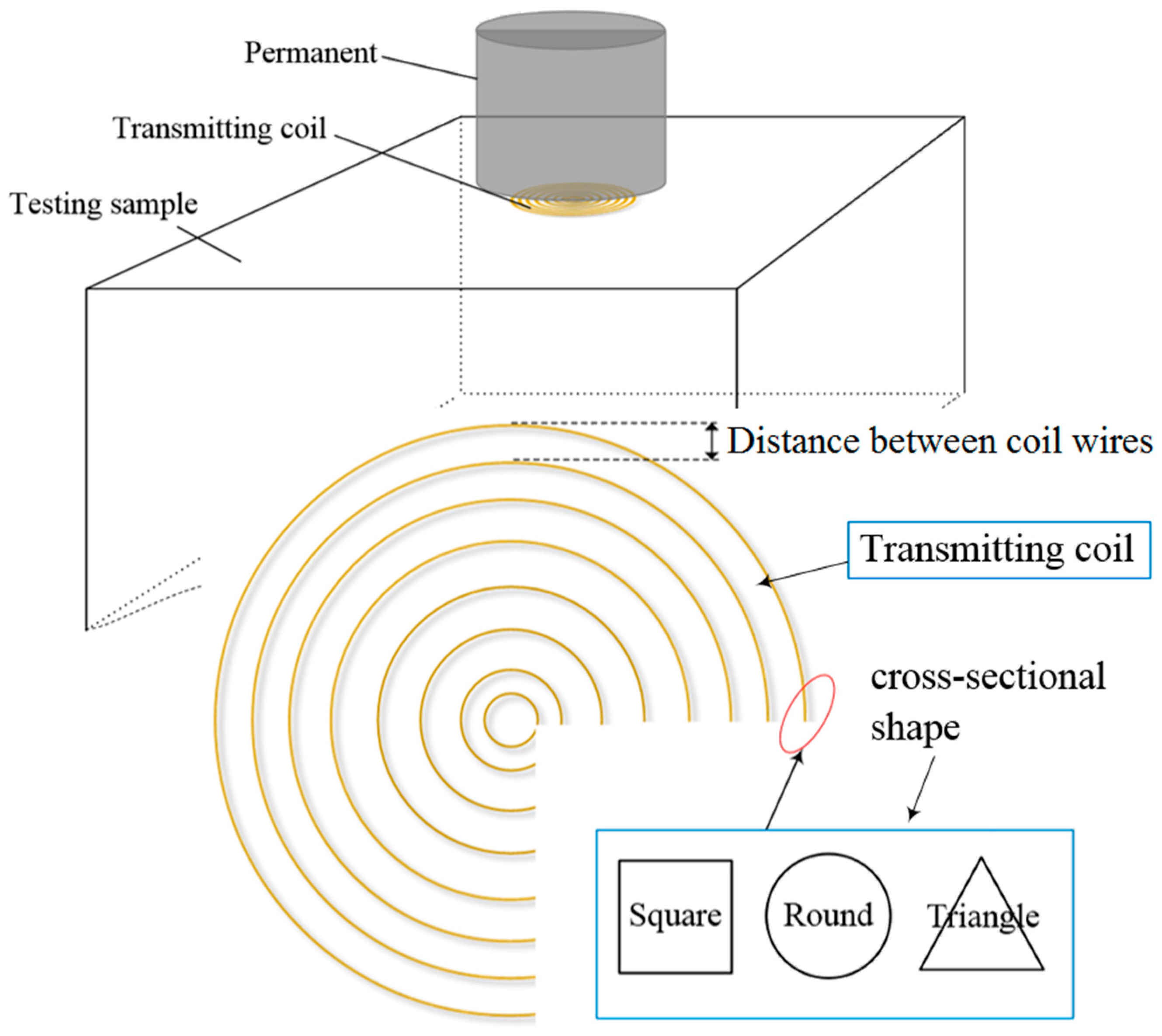
An EMAT system based on the spiral coil transmitting, which can generate shear wave to propagate into the materials, as shown in Figure 2, is analyzed. The purpose of this paper is to extend the study of the coil configurations, focusing on the effects of coil wires’ cross-sectional shape, coil wires’ cross-sectional area, and distance between coil wires on the conversion efficiency.
Due to the symmetries of the permanent magnet and the spiral coil, the two-dimensional (2-D) axis-symmetric model is used. As can be seen in Figure 3, the symmetric axis is set to the y axis, the radius and the height of the permanent magnet are 20 mm and 10 mm, and the radius and the height of the testing sample are 25 mm and 10 mm. Generally, the finite air domain is defined or hypothesized when a numerical model of the magnetic field is established. As shown in Figure 3, the air domain boundaries consist of three boundaries due to the symmetries of the model. In addition, to obtain a fine numerical solution, the triangular mesh element is adopted, and the number of the mesh elements is proximately 80,000 in the computation domain. Further, because the induced eddy current distributes in the skin depth of the testing sample, the boundary layers are used in the surface of the testing sample and the number is set to eight, while the stretching factor is 1.2.
Based on a 2-D axis-symmetric geometric model, the simulations of the magnetic field and the electric field can be performed by applying the control Equations (5) and (11) in the commercial software Comsol multiphysics code. In order to solve these equations, two boundary conditions are needed. (a) When the magnetic field is calculated, the finite air domain which contains the permanent magnet is needed, and the normal magnetic field intensity on the air domain boundary is set to zero. (b) The external current density of the transmitting coil can be calculated by , where Acoil is the cross-sectional area of a coil wire.
2.3. Model Validation
Table 1 lists the geometrical, operating, and physical parameters for the magnetic field and the induced eddy current modeling. The present model is numerically solved by a commercial software Comsol multiphysics code. After computing, the results including magnetic field flux density, induced eddy current density, Lorentz force, and coil impedance can be directly obtained.
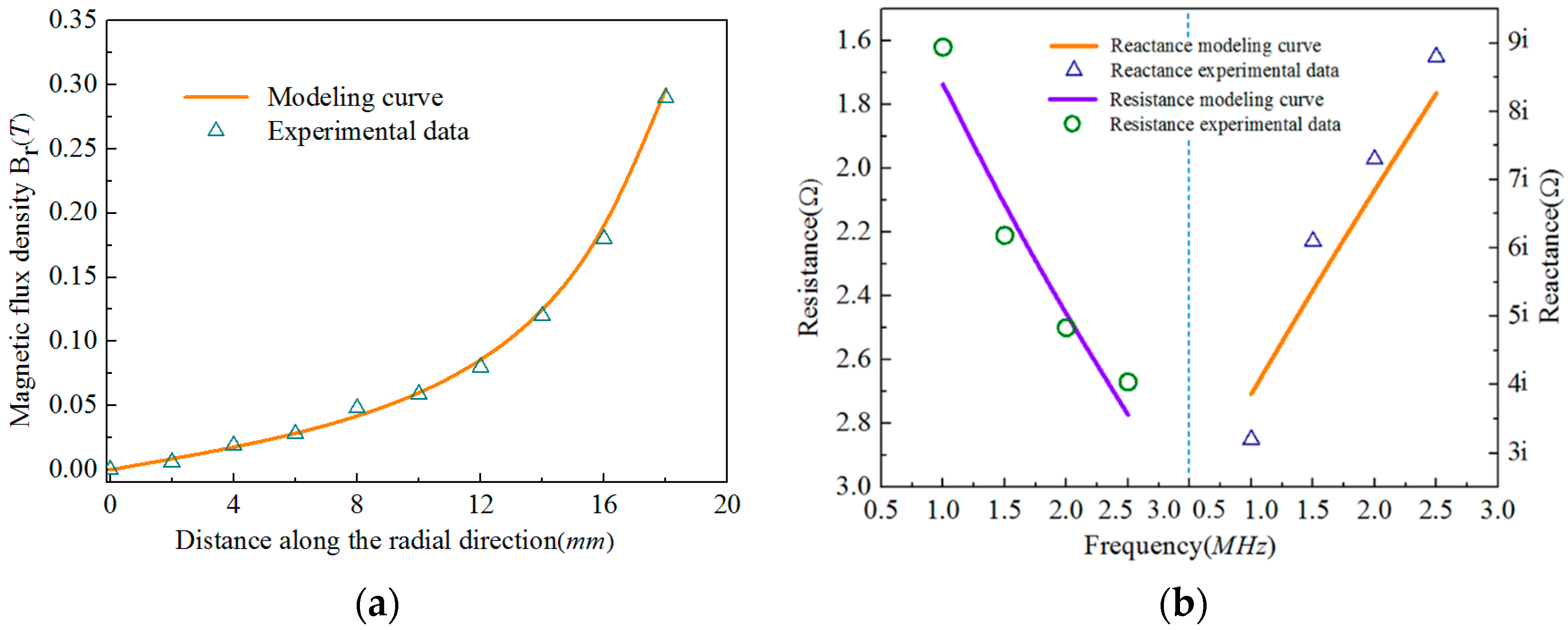
To validate the present model, the Lake Shore 475 Gauss Meter, which has the same functional parameters as the present model, is used to measure the magnetic flux density of the permanent magnet. Because the static magnetic field generated by the permanent magnet can be conveniently obtained, the standard probe of the Lake Shore 475 Gauss Meter is used. In order to compare the experimental data with the modeling data, a real cylindrical permanent magnet with the remanent flux density of 1.2 T is selected as the testing sample. Its size can be seen in Table 1; the radius and the height of the permanent magnet are 20 mm and 10 mm. Due to the time cost, 10 points along the radial direction on the surface of the permanent magnet N pole is considered as the experimental measurable points. The measurable data is then used to compare with the modeling data. As shown in Figure 4a, the magnetic flux density along the radial direction of the permanent magnet is obtained by modeling and experiment, and the modeling results have a good agreement with the experimental data.
The experimental case 2 adopts a Vector Network Analyzer (VNA) to measure the impedance of the transmitting coil. According to the definition of the transmitting coil in the modeling, the real testing spiral coils adopting enameled copper coils are used to measure its impedance. To avoid the repeated works, the impedance of a spiral enameled copper coil with a round cross-section is experimentally measured. In addition, the diameter of the spiral coil using measure impedance is 19 mm, and the diameter of the coil wire is 0.3 mm. By adjusting the frequency range of the Vector Network Analyzer (VNA), the impedance of the spiral coil under different frequencies can be obtained. As shown in Figure 4b, the impedance values from modeling also show a good agreement with the experimental data. Therefore, the present model can be validated by the above experiments.
3. Results and Discussion
To investigate the effects of the coil configurations on conversion efficiency, the coil configuration parameters including coil cross-sectional area, coil wire cross-sectional shape, and distance between coil wires are provided, as shown in Table 2; the excitation frequencies are also given. The present model is then used to calculate the Lorentz force at different coil configuration parameters and at different excitation frequencies.
3.1. Effect of Coil Cross-Sectional Area
This section focuses on the cross-sectional area of the transmitting coil. There are five data which refer to different coil cross-sectional areas, as shown in Table 2, for the candidates of the modeling parameters. For the traditional spiral coils, its cross-sectional shape is round. Generally, the diameter of the coil wires, as a key research parameter, is used in many reports of EMAT [28]. Corresponding to the five coil cross-sectional areas mentioned in Table 2, the diameters of the coil wires with a round cross-section are 0.1 mm, 0.2 mm, 0.3 mm, 0.4 mm, and 0.5 mm, respectively. Besides the coil wires with a round cross-section, other coil wires with irregular cross-sectional shapes such as triangle and square are also used in this paper. For convenient comparisons of the coils with different types of cross-sectional shape, coil cross-sectional area is therefore used as a key parameter to study the conversion efficiency of EMAT.
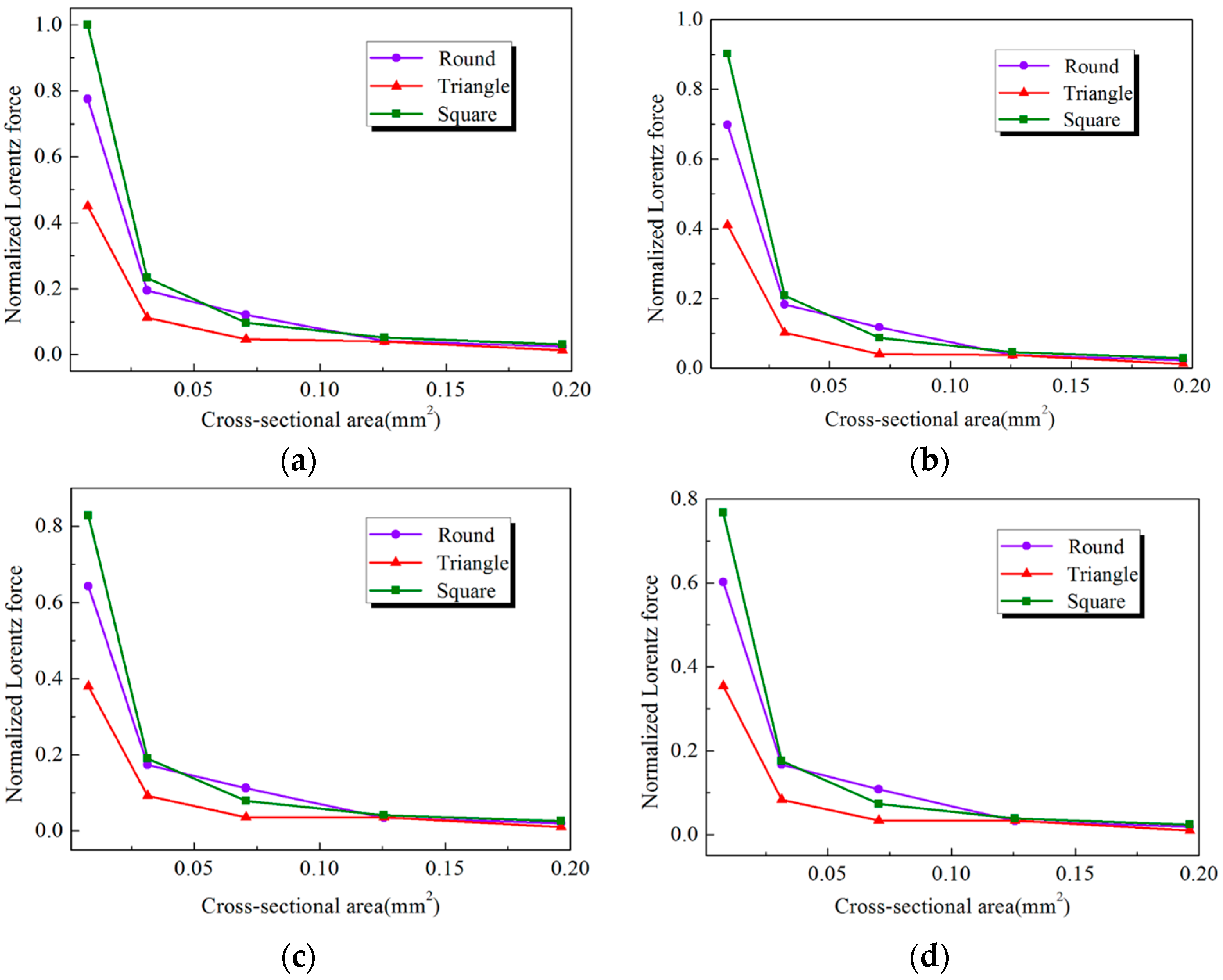
Due to the Lorentz force generated by the transmitting coil, the ultrasonic wave is formed and propagated into the materials. Therefore, the relationships between the Lorentz force and the transmitting coil are presented, as shown in Figure 5. In Figure 5a, it can be seen that as the coil cross-sectional area increases, the Lorentz force exhibits a sharp decrease at the beginning and a gradual, mild decrease later. In addition, when the coil cross-sectional shape is different, the changing trend of the curves is similar. Further, by observing Figure 5b–d, when the excitation frequency of the coil is different, the coil wire’s cross-sectional area has also same effects on the Lorentz force. The relationship between the excitation frequencies of the coil and the Lorentz force can also be seen in Figure 5; when the excitation frequency of the coil increases, the Lorentz force exhibits a mild decrease.
As can be seen from Equation (14), the Lorentz force is a result of the interaction between the magnetic field and the induced eddy current. In this paper, the magnetic field generated by the permanent magnet is not changed, so the different cross-sectional areas of the coil may have different distributions of the induced eddy current in the skin depth of the testing sample. For a spiral coil with the same radius, a smaller cross-sectional area means that the coil has a greater number of turns. If the spiral coil has more turns, the distribution of the induced eddy current will be more close-knit, which consequently results in a stronger density of the induced eddy current. Thus, a smaller cross-sectional area can lead to a larger Lorentz force.
These phenomena indicate that the coil wire’s cross-sectional area has a significant effect on the conversion efficiency of EMAT, and the effect is not independent from other factors. It is also found that the smaller the cross-sectional area, the larger the conversion efficiency. Therefore, when the electromagnetic acoustic transducer is produced or designed, the cross-sectional area of the coil wires must be as a key design factor and the corresponding frequency range must be cautiously selected.
3.2. Effect of Coil Wire Cross-Sectional Shape
As a spiral coil, the coil wire’s cross-sectional shape is usually round in many applications [28]. On coils with other cross-sectional shapes, there have been little reports in recent years. Therefore, to further obtain the optimized transmitting coil to improve the performance and efficiency of EMAT, it is necessary to investigate the effect of coil cross-sectional shape on the conversion. The previous section has mentioned that a smaller cross-sectional area can obtain better conversion efficiency. So, the relationship between a coil wire’s cross-sectional shape and the Lorentz force is investigated at a given cross-sectional area (which is 0.00785 mm2) and different excitation frequencies.
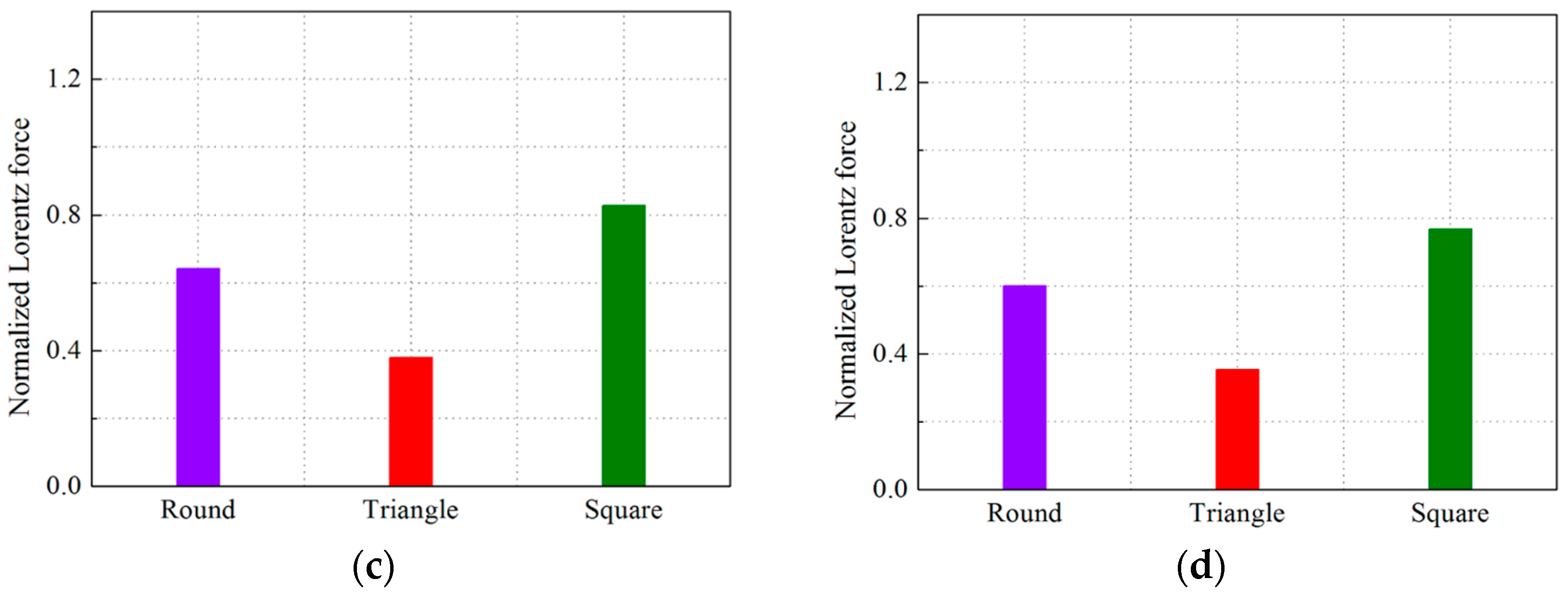
Figure 6 lists the comparisons of the Lorentz force under different cross-sectional shapes and different excitation frequencies. When the excitation frequencies are 1 MHz, 1.5 MHz, 2 MHz, and 2.5 MHz, respectively, there is a common trend that the square cross-sectional shape can generate the largest Lorentz force. In addition, for different cross-sectional shapes mentioned in this paper, square is better than round, and round is better than triangle. It is also found that the square can increase the Lorentz force at the frequency of 1 MHz by 22.5% compared to the traditional round cross-section. This phenomenon indicates that the conversion efficiency of the shear wave EMAT can be enhanced by employing the modified transmitting coil with a square cross-section, and the conversion efficiency can also increase by 22.5% when the transducer is set to 1 MHz frequency.
The main reason why a transmitting coil with a square cross-sectional shape can generate greater conversion efficiency than other cross-sectional shapes is due to the generation of the dynamic magnetic field due to the alternating current in the transmitting coil. When a pulsing alternating current travels through the transmitting coil, the dynamic magnetic field will be formed around the circumferential direction of the coil wires. However, different cross-sectional shapes of the coil wires will lead to different distributed directions of the dynamic magnetic field. For a shear wave EMAT based on a spiral coil, only the magnetic field direction perpendicular to the surface of the testing sample is able to generate the vibration of the shear direction. When the cross-sectional shape is square, the dynamic magnetic field of two sides on the coil wires will have a direction perpendicular to the surface of the testing sample. This means that a large proportion of the dynamic magnetic field generated by the transmitting coil can be used to generate the vibration of the shear direction. For the transmitting coil with the round cross-section or triangle cross-section, the dynamic magnetic field with a direction perpendicular to surface of the testing sample makes up only a small portion, although the round cross-section has a larger portion than the triangle cross-section.
Therefore, when the cross-sectional shape of the transmitting coil is square, a larger Lorentz force will be generated. In other word, when a shear wave EMAT based on a spiral coil system is designed, the selection of the transmitting coil with a square cross-section will be able to generate greater conversion efficiency.
3.3. Effect of Distance between Coil Wires
For a spiral coil, distances between coil wires are equal at every turn. When the distance between the coil wires is changed, the distribution of the eddy current in the skin depth induced by the transmitting coil will undergo a corresponding change. The changing eddy current will affect conversion efficiency of EMAT; thus, it is also necessary to study the distance between the coil wires.
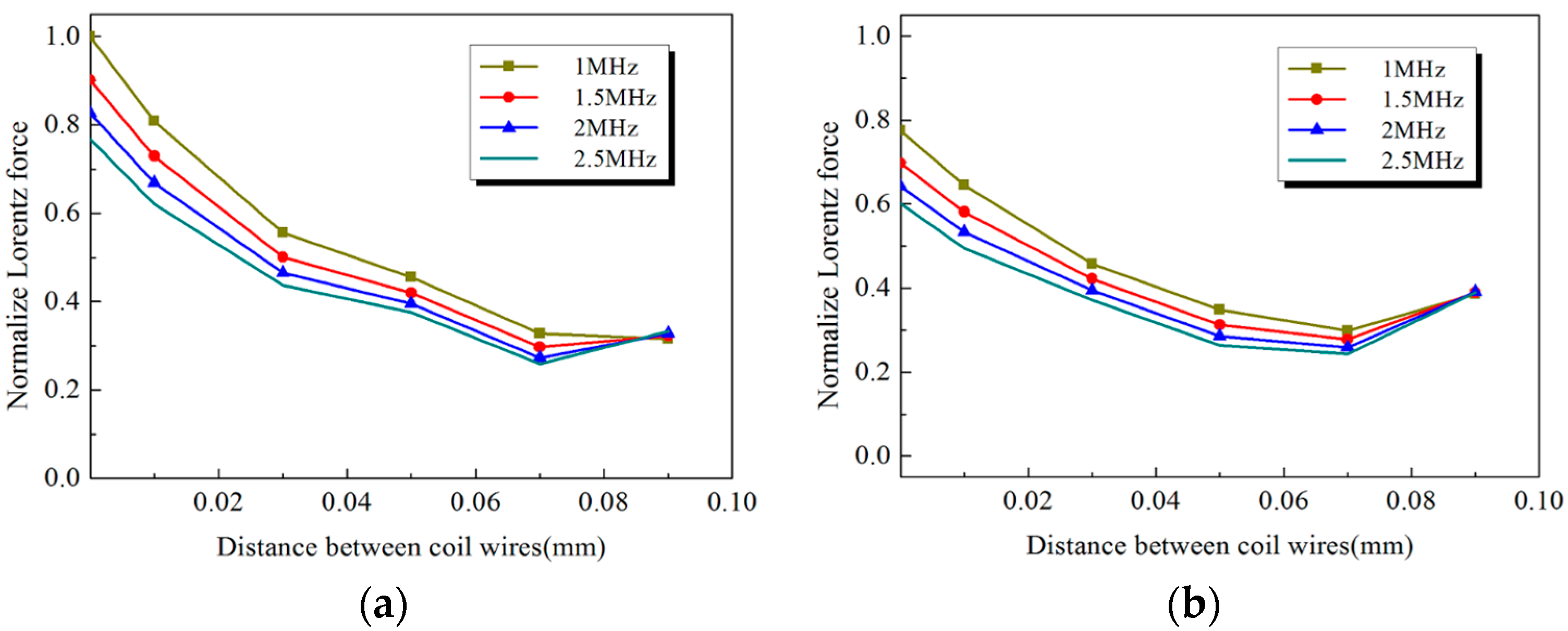
As can be seen in Figure 7, the modeling curves of the transmitting coil with different distances between coil wires and the Lorentz force are established at different excitation frequencies and for different cross-sectional shapes. In Figure 7a, as distance between the coil wires increases from 0.01 mm to 0.07 mm, while the Lorentz force exhibits a sharp decrease. However, when the distance between the coil wires is greater than 0.07 mm, the Lorentz force increases gradually. This means that the distance between the coil wires has a key value corresponding to the worst conversion efficiency. In order to further validate this viewpoint, the traditional coil which has a round cross-section is also analyzed, as shown in Figure 7b, and the relationships between the Lorentz force and the distance between the coil wires show a similarity, and the key value is also 0.07 mm. Therefore, when an EMAT system is designed, coil winding must avoid this key value.
When the distance between the coil wires is smaller, this means that the spiral coil is more close-knit. The close-knit coil will directly lead to a more uniform and a larger induced eddy current density field in a finite domain. However, with the increase of the distance between the coil wires, the induced eddy current density field will become non-uniform, which will lead to an interaction of the induced eddy current of the coil wires to reduce the induced eddy current density. When the distance between the coil wires is more than 0.07 mm, the induced eddy current of each wire will be independent. This means that the induced eddy current of the coil wires has no interaction at this condition. So, when the distance between the coil wires is more than 0.07 mm, the Lorentz force increases.
4. Conclusions
In this paper, a new numerical model for the electromagnetic conversion of EMAT is reasonably developed and validated. In particular, the Lorentz force equation is incorporated into the magnetic field model, as well as the frequency domain equations of the dynamic magnetic field and the eddy current. A simulation is then performed to investigate the effects of the coil configurations, including coil wires’ cross-sectional shape, coil wires’ cross-sectional area, and distance between coil wires, on the conversion efficiency of shear wave EMAT on 7050 aluminum alloy. Modeling results show that the conversion efficiency is increased by 22.5% after using the transmitting coil with a square cross-section at the frequency of 1 MHz. In addition, the coil wires’ cross-sectional area also has a significant influence on the conversion efficiency. Decreasing the area of the coil wires’ cross-section can generate a larger Lorentz force, which can consequently improve the performance and efficiency of EMAT. Further, the distance between the coil wires has a key value corresponding to the worst conversion efficiency, and the key value is 0.07 mm. Therefore, when an EMAT system is designed, the transmitting coil winding must avoid this key value.
Acknowledgments
The authors greatly appreciate the support from the Project of State Key Laboratory of High Performance Complex Manufacturing, Central South University under Award ZZYJKT2017-06. The authors also wish to express their appreciation to Wenze Shi and Liangchen Tan for their help.
Author Contributions
All authors contributed equally to this article. Especially, Lei Han and Yunxin Wu established numerical model and carried out the simulation; Hai Gong, Jiangang Yang, and Wei Li managed the data information. All authors contributed to the writing of the paper.
Conflicts of Interest
The authors declare no conflict of interest.
References
- Dobbs, E.R.; Llewellyn, J.D. Generation of ultrasonic waves without using a transducer. Non-Destr. Test. 1971, 4, 49–56. [Google Scholar] [CrossRef]
- Moran, T.J.; Panos, R.M. Electromagnetic generation of electronically steered ultrasonic bulk waves. J. Appl. Phys. 1976, 47, 2225–2227. [Google Scholar] [CrossRef]
- Thompson, R.B. Generation of horizontally polarized shear waves in ferromagnetic materials using magnetostrictively coupled meander-coil electromagnetic transducers. Appl. Phys. Lett. 1979, 34, 175–177. [Google Scholar] [CrossRef]
- Thompson, R.B. The relationship between radiating body forces and equivalent surface stresses: Analysis and application to EMAT design. J. Nondestr. Eval. 1980, 1, 79–85. [Google Scholar] [CrossRef]
- Lee, J.K.; Kim, Y.Y. Tuned double-coil EMATs for omnidirectional symmetric mode lamb wave generation. NDT E Int. 2016, 83, 38–47. [Google Scholar] [CrossRef]
- Wang, S.; Kang, L.; Li, Z.; Zhai, G.; Zhang, L. 3-D modeling and analysis of meander-line-coil surface wave EMATs. Mechatronics 2012, 22, 653–660. [Google Scholar] [CrossRef]
- Edwards, R.S.; Dixon, S.; Jian, X. Characterisation of defects in the railhead using ultrasonic surface waves. NDT E Int. 2006, 39, 468–475. [Google Scholar] [CrossRef]
- Zhao, X.; Varma, V.K.; Mei, G.; Ayhan, B.; Kwan, C. In-line nondestructive inspection of mechanical dents on pipelines with guided shear horizontal wave electromagnetic acoustic transducers. J. Press. Vessel Technol. 2005, 127, 304–309. [Google Scholar] [CrossRef]
- Clough, A.R.; Edwards, R.S. Characterisation of hidden defects using the near-field ultrasonic enhancement of Lamb waves. Ultrasonics 2015, 59, 64–71. [Google Scholar] [CrossRef] [PubMed]
- Nagy, P.B.; Simonetti, F.; Instanes, G. Corrosion and erosion monitoring in plates and pipes using constant group velocity Lamb wave inspection. Ultrasonics 2014, 54, 1832–1841. [Google Scholar] [CrossRef] [PubMed]
- Cheng, L.; Kogia, M.; Mohimi, A.; Kappatos, V.; Selcuk, C.; Gan, T.H. Crack characterisation using invariable feature extraction in stainless steel specimen used for absorber tubes of CSP applications via EMAT. Renew. Energy 2017, 101, 771–781. [Google Scholar] [CrossRef]
- Nakamura, N.; Ogi, H.; Hirao, M. EMAT pipe inspection technique using higher mode torsional guided wave T (0, 2). NDT E Int. 2017, 87, 78–84. [Google Scholar]
- Petcher, P.A.; Potter, M.D.G.; Dixon, S. A new electromagnetic acoustic transducer (EMAT) design for operation on rail. NDT E Int. 2014, 65, 1–7. [Google Scholar] [CrossRef]
- Petcher, P.A.; Dixon, S. Weld defect detection using PPM EMAT generated shear horizontal ultrasound. NDT E Int. 2015, 74, 58–65. [Google Scholar] [CrossRef]
- Shi, W.; Wu, Y.; Gong, H.; Zhang, T.; Tan, L.; Han, L.; Yang, J.; Li, W. Optimal design of spiral coil electromagnetic acoustic transducers considering lift-off sensitivity operating on non-ferromagnetic media. Nondestr. Test. Eval. 2016, 9, 1–19. [Google Scholar] [CrossRef]
- Clough, M.; Fleming, M.; Dixon, S. Circumferential guided wave EMAT system for pipeline screening using shear horizontal ultrasound. NDT E Int. 2017, 86, 20–27. [Google Scholar] [CrossRef]
- Thring, C.B.; Fan, Y.; Edwards, R.S. Focused Rayleigh wave EMAT for characterisation of surface-breaking defects. NDT E Int. 2016, 81, 20–27. [Google Scholar] [CrossRef]
- Thring, C.B.; Fan, Y.; Edwards, R.S. Multi-coil focused EMAT for characterisation of surface-breaking defects of arbitrary orientation. NDT E Int. 2017, 88, 1–7. [Google Scholar] [CrossRef]
- Quan, G.; Mao, Y.; Li, G.; Lv, W.Q.; Wang, Y.; Zhou, J. A characterization for the dynamic recrystallization kinetics of as-extruded 7075 aluminum alloy based on true stress–strain curves. Comput. Mater. Sci. 2012, 55, 65–72. [Google Scholar] [CrossRef]
- Pei, C.; Zhao, S.; Xiao, P.; Chen, Z. A modified meander-line-coil EMAT design for signal amplitude enhancement. Sens. Actuators Phys. 2016, 247, 539–546. [Google Scholar] [CrossRef]
- Isla, J.; Seher, M.; Challis, R.; Cegla, F. Optimal Impedance on Transmission of Lorentz Force EMATs; AIP Publishing: Melville, NY, USA, 2016. [Google Scholar]
- Ashigwuike, E.; Balachandran, W.; Thomas, S.; Mackay, R. Numerical study of EMAT coil structure based on finite element method. Pet. Technol. Dev. J. 2013, 3, 8–24. [Google Scholar]
- Huang, S.; Zhao, W.; Zhang, Y.; Wang, S. Study on the lift-off effect of EMAT. Sens. Actuators Phys. 2009, 153, 218–221. [Google Scholar] [CrossRef]
- Griffiths, D.J. Introduction to Electrodynamics; Prentice Hall: Upper Saddle River, NJ, USA, 1962. [Google Scholar]
- Reitz, J.R.; Milford, F.J.; Christy, R.W. Foundations of Electromagnetic Theory; Addison-Wesley Publishing Company: Boston, MA, USA, 2008. [Google Scholar]
- Cheng, D.K. Field and Wave Electromagnetics; Addison Wesley: Boston, MA, USA, 1989. [Google Scholar]
- Jin, J.M. The Finite Element Method in Electromagnetics; John Wiley & Sons: Hoboken, NJ, USA, 2015. [Google Scholar]
- Ribichini, R.; Cegla, F.; Nagy, P.B.; Cawley, P. Experimental and numerical evaluation of electromagnetic acoustic transducer performance on steel materials. NDT E Int. 2012, 45, 32–38. [Google Scholar] [CrossRef]
Figure 1.
Schematic of electromagnetic-acoustic conversion.

Figure 2.
Geometrical model schematic of an electromagnetic acoustic transducer system.

Figure 3.
Geometrical schematic of a two -dimensional (2-D) axis-symmetric model.
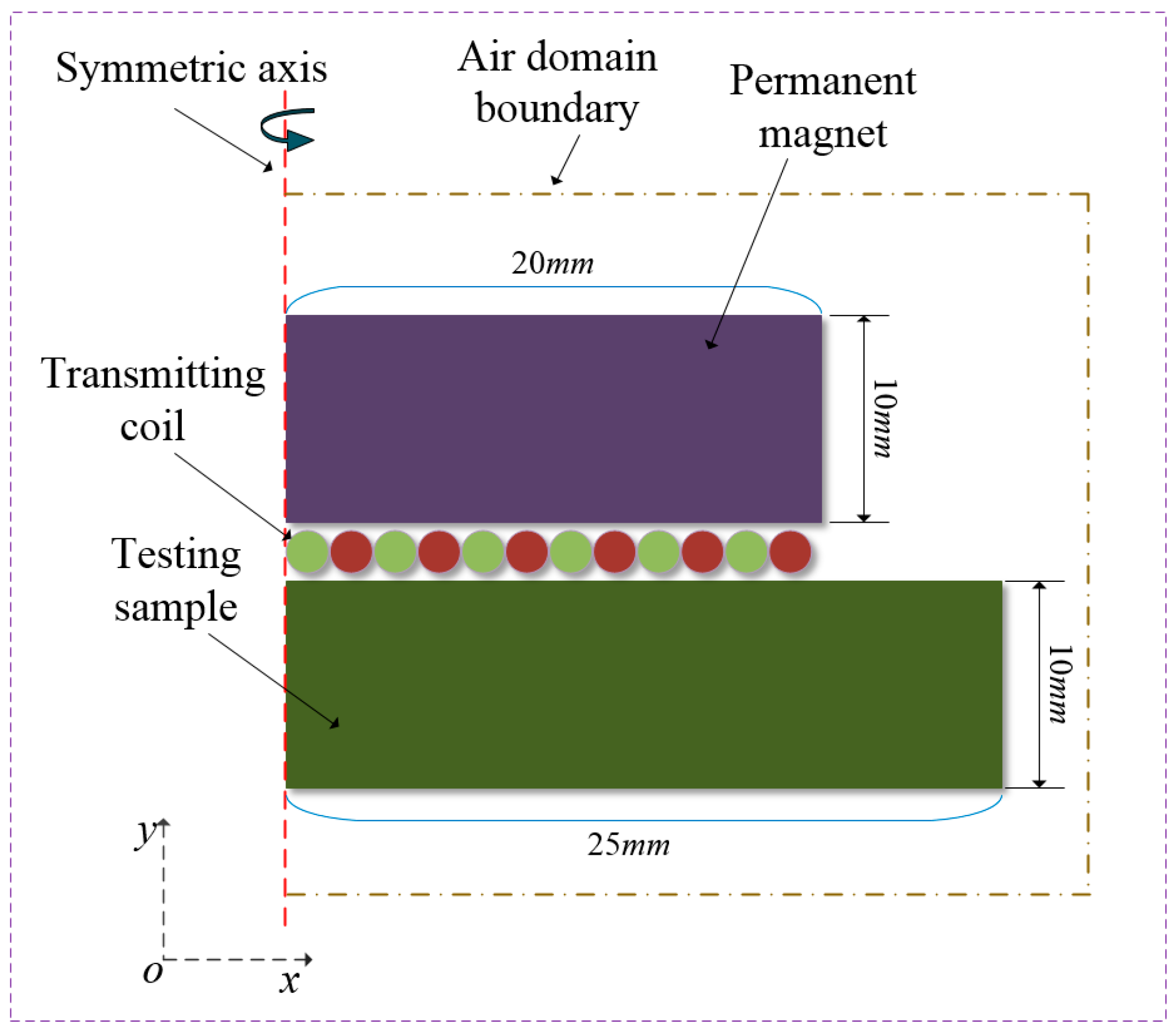
Figure 4.
Comparison of the modeling magnetic flux density and the coil impedance with experimental data. (a) Magnetic field flux density; (b) Coil impedance.
Figure 4.
Comparison of the modeling magnetic flux density and the coil impedance with experimental data. (a) Magnetic field flux density; (b) Coil impedance.

Figure 5.
Normalized Lorentz force in skin depth with different coil cross-sectional areas and cross-sectional shapes. (a) f = 1 MHz; (b) f = 1.5 MHz; (c) f = 2 MHz; (d) f = 2.5 MHz.
Figure 5.
Normalized Lorentz force in skin depth with different coil cross-sectional areas and cross-sectional shapes. (a) f = 1 MHz; (b) f = 1.5 MHz; (c) f = 2 MHz; (d) f = 2.5 MHz.

Figure 6.
Normalized Lorentz force in skin depth with different coil wires’ cross-sectional shapes. (a) f = 1 MHz; (b) f = 1.5 MHz; (c) f = 2 MHz; (d) f = 2.5 MHz.
Figure 6.
Normalized Lorentz force in skin depth with different coil wires’ cross-sectional shapes. (a) f = 1 MHz; (b) f = 1.5 MHz; (c) f = 2 MHz; (d) f = 2.5 MHz.


Figure 7.
Normalized Lorentz force in skin depth with different distances between coil wires and excitation frequencies. (a) Square cross-section; (b) Round cross-section.
Figure 7.
Normalized Lorentz force in skin depth with different distances between coil wires and excitation frequencies. (a) Square cross-section; (b) Round cross-section.

Table 1.
Basic parameters for modeling EMAT.
| Description, Symbol | Value, Unit |
|---|---|
| Remanent flux density, Br | 1.2 T |
| Relative permeability | 1 |
| Relative permittivity | 1 |
| Coil radius | 9.5 mm |
| Lift-off | 0.1 mm |
| Transmitting coil current | 30 A |
| Electrical conductivity, Al | |
| Electrical conductivity, magnet | |
| Electrical conductivity, coil | |
| Permanent magnet size | |
| Test sample size |
Table 2.
Coil configuration parameters and excitation frequencies.
| Description | Value |
|---|---|
| Frequency (MHz) | 1, 1.5, 2, 2.5 |
| Coil cross-sectional area (mm2) | 0.00785, 0.0314, 0.07065, 0.1256, 0.19625 |
| Coil wire cross-sectional shape | Round, Triangle, Square |
| Distance between coil wires (mm) | 0.01, 0.03, 0.05, 0.07, 0.09 |
© 2017 by the authors. Licensee MDPI, Basel, Switzerland. This article is an open access article distributed under the terms and conditions of the Creative Commons Attribution (CC BY) license (http://creativecommons.org/licenses/by/4.0/).
Share and Cite
MDPI and ACS Style
Wu, Y.; Han, L.; Gong, H.; Yang, J.; Li, W. Effect of Coil Configuration on Conversion Efficiency of EMAT on 7050 Aluminum Alloy. Energies 2017, 10, 1496. https://doi.org/10.3390/en10101496
AMA Style
Wu Y, Han L, Gong H, Yang J, Li W. Effect of Coil Configuration on Conversion Efficiency of EMAT on 7050 Aluminum Alloy. Energies. 2017; 10(10):1496. https://doi.org/10.3390/en10101496
Chicago/Turabian StyleWu, Yunxin, Lei Han, Hai Gong, Jiangang Yang, and Wei Li. 2017. "Effect of Coil Configuration on Conversion Efficiency of EMAT on 7050 Aluminum Alloy" Energies 10, no. 10: 1496. https://doi.org/10.3390/en10101496
Note that from the first issue of 2016, this journal uses article numbers instead of page numbers. See further details here.