
Analytical Derivation of Electrical-Side Maximum Power Line for Wind Generators

1
Department of Electrical Engineering and Electronics, Ariel University of Samaria, Ariel 40700, Israel
2
Department of Electrical and Computer Engineering, Ben-Gurion University of the Negev, Beer-Sheva 84105, Israel
*
Author to whom correspondence should be addressed.
Energies 2017, 10(10), 1498; https://doi.org/10.3390/en10101498
Submission received: 16 August 2017
/
Revised: 18 September 2017
/
Accepted: 25 September 2017
/
Published: 26 September 2017
(This article belongs to the Special Issue Wind Generators Modelling and Control)
Abstract
:In order to enhance the maximum power point tracking (MPPT) speed of solar generators, offline calculated maximum power line (MPL) is often used as a feed-forward signal added to the output of MPPT controller. MPL is nonlinear static electrical characteristic of renewable energy generators connecting all the maximum power points for given temperature. In this letter, electrical side MPL is derived for a typical wind turbine generator (WTG). It is shown that MPLs of solar and wind generators possess similar structure, supporting the similarity between the two energy conversion processes.
1. Introduction
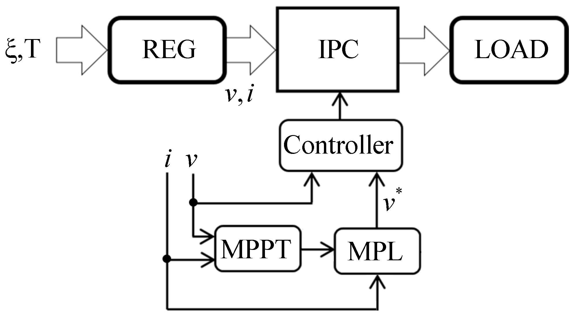
Renewable energy sources possess the so-called soft source characteristics, requiring careful interfacing (i.e., maximum power point tracking, MPPT) to allow optimal utilization in terms of cost and reliability [1,2]. A generalized renewable energy conversion system is shown in Figure 1, consisting of a renewable energy generator (REG), an interfacing power converter (IPC), and a load.
Typical inputs affecting REG operation are the energy producing variable ξ (solar irradiation, wind, etc.) and the temperature T. On the electrical side of the REG, voltage and current are sampled and fed back into an MPPT algorithm in order to utilize as much harvested energy as possible [3,4]. In order to increase the response time of conventional (MPP) trackers and decrease the effect of fast varying energy processing variable, the authors of [5] proposed the inclusion of a feed-forward term which predicts REG MPP voltage (v*) from measured REG current I according to a priori calculated MPL, as shown in Figure 2. Thus, the feed-forward term brings the operational point of the IPC to the vicinity of MPP and the tracker performs only the fine-tuning required due to parameter inaccuracies and slow varying temperature. The method is used in both solar [6] and wind [7] energy conversion systems; nevertheless, the latter typically employ mechanical rather than electrical side MPL, utilizing torque control requiring mechanical sensors [8]. In this brief, electrical side MPL is derived for wind generators, treated as electrical sources to allow application of the well-studied methods of interfacing photovoltaic generators to wind turbine generators without the need of mechanical sensors.
2. Wind Turbine Generator (WTG) MPL Derivation
Wind power extracted by a wind turbine is given by [9]
where ρ is air density, A is the area swept by turbine’s blades, vW is wind speed, and CP is power coefficient, which is a nonlinear function of turbine tip-speed ratio (TSR), given by
with R denoting blade radius. Substituting (3) into (2), there is
The typical CP-versus-TSR curve is bell-shaped, possessing a single MPP, defined by (TSROPT, CP,MAX) pair which is constant for a given wind turbine. Hence, maximum power is extracted from the wind blowing with speed vW by rotating the turbine at
and is given by
Note that KMPP is temperature-dependent since it is influenced by air density. Consequently, the relation between wind-produced torque and turbine speed at MPP is given by
defining mechanical MPL of the wind turbine, typically used in the literature.
Consider (without loss of generality) a WTG, consisting of wind turbine WT, driving DC generator (DCG) via stiff gear G, as shown in Figure 3. Low-frequency dynamics of the WTG is governed by
where JT and BT are turbine moment of inertia and friction coefficient, respectively, ωT is turbine angular speed, TW is wind-produced torque, and TT is DCG torque, reflected to the low-speed turbine shaft. The transmission relates turbine and generator speeds and torques as
with ηG denoting gear efficiency. Dynamics of the generator mechanical part is governed by
where JM, BM, and ηM are machine moment of inertia, friction coefficient, and efficiency, respectively, i is DCG output current, and KT is DCG torque constant. Combining (7)–(9), generator-side dynamics is obtained as
with
Electrical side DCG behavior is described by
with LM and RM denoting machine coil inductance and resistance, respectively, e = KT·ωM signifying back electromotive force and v symbolizing DCG terminal voltage. Since electrical time constant is typically much lower than the mechanical one, (12) may be approximated by
neglecting phase inductance dynamics. Further substituting DCG speed with back electromotive force results in the electrical-side system of equations, given by
In steady state, (14) reduces to
Combining (6) and (8) with (15) gives after rearranging
Electrical-side MPL is obtained by solving (16) as
In some cases, REG power rather than voltage is fed back to the controller; i.e., power-voltage plane MPL is required, obtained as
3. Numerical Example
Consider a WTG-DCG system, shown in Figure 3, characterized by the following parameters:
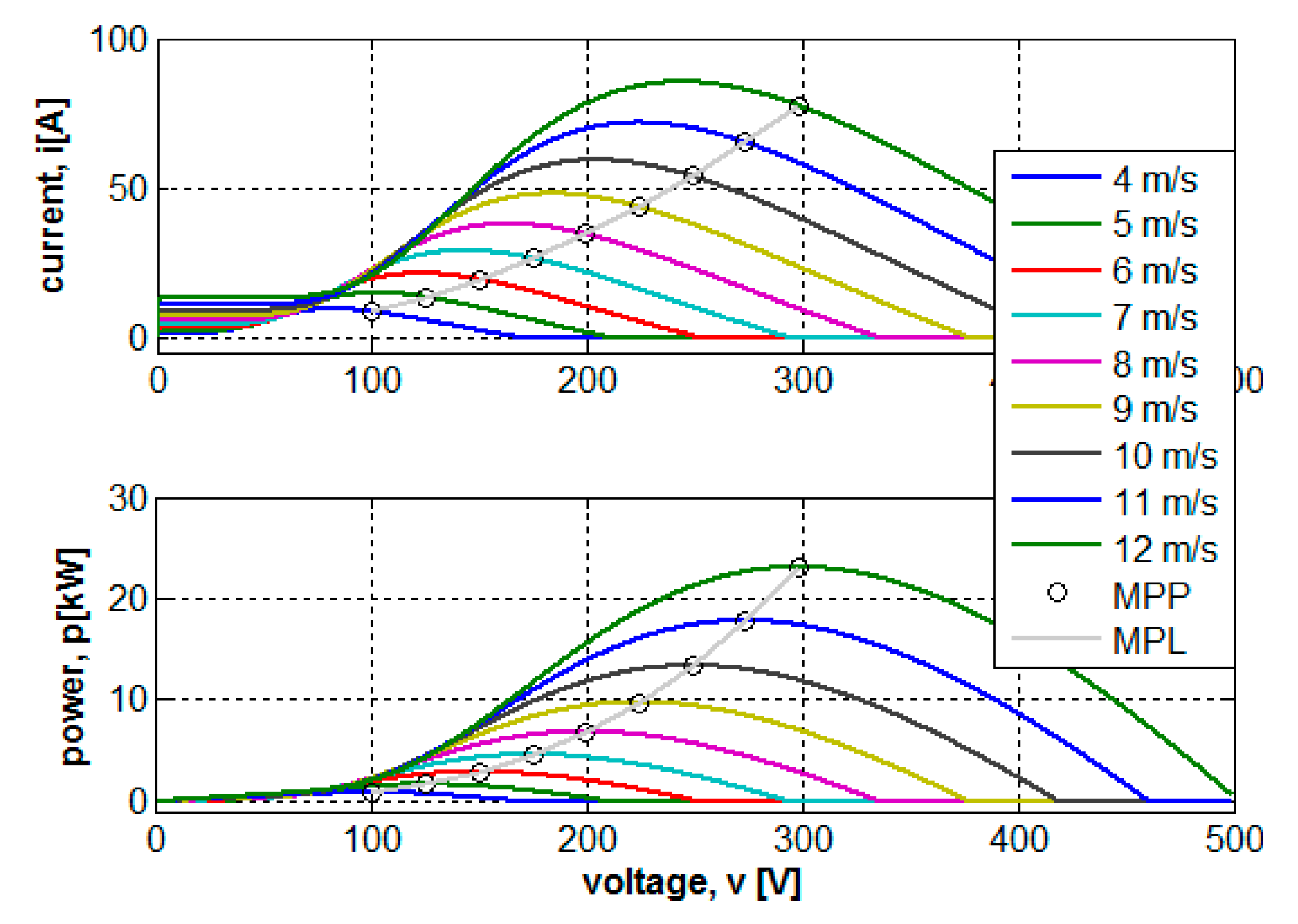
Turbine nominal power 24 kW, base wind speed 12 m/s, base rotational speed 60 rpm, total moment of inertia 10 × 10−3 N·m·s2/rad, KT = 0.02 Nm/A, gear ratio 10, DCG rotor resistance 40 mΩ. Power coefficient versus tip-speed ratio was adopted from [10]. Figure 4 presents the electrical side characteristics of the system for different wind speeds at 25 °C with corresponding MPPs specified by circles. The MPLs shown were calculated according to (17) and (18). It may be concluded that estimated MPLs accurately link all the indicated MPPs in both current and power domains.
4. Discussion
Several important remarks should be emphasized as follows:
- Even though a simple model of a DC Generator was utilized, it may be easily shown that in case permanent magnet generator (PMG) driving a three-phase diode rectifier (DR) is utilized, the solution form remains (some scaling should be carried out). Interested readers are referred to [7,11] for detailed modeling of a PMG-DR unit.
- The derived expression (17) contains KMPP and is therefore temperature-dependent. This is the main reason (apart from parameter uncertainty and possible variations) for the necessity of employing MPPT algorithm in addition to utilizing MPL. Nevertheless, since both temperature and parameter variations are relatively slow, high-bandwidth MPPT is unnecessary.
- The MPL for solar generators was recently derived in [12] and is given bywhere χ(∙) is a nonlinear operator (Lambert-W function related) and Rs is solar generator output series resistance. Note that the form of (18) is similar to that of (17), including temperature dependence. This further supports the similarity between solar and wind generators, recently pointed out in [13].
- It should be pointed out that if friction and series resistance are neglected, (17) reduces toindicating pure quadratic relation between DC current and voltage. This result was reported in some earlier works. Furthermore, comparing (19) to the right-hand side of (6) reveals that in case the DCG is lossless (i.e., perceived as an ideal mechanical-to-electrical energy transformer), (19) is a mechanical-to-electrical domain transformation of (6); i.e., v ~ ωT and i ~ TW.
5. Conclusions
In this brief, electrical-side MPL for wind turbine generators was derived. The finding allows a wind generator to be treated as an electrical source and thus potentially makes it possible to apply well-studied methods of interfacing photovoltaic generators to wind turbine generators. Moreover, mechanical sensorless operation is enabled, requiring information regarding electrical-side variables only.
Conflicts of Interest
The authors declare no conflict of interest.
References
- Gadelovits, S.; Kuperman, A.; Sitbon, M.; Aharon, I.; Singer, S. Interfacing renewable energy sources for maximum power transfer—Part 1: Statics. Renew. Sustain. Energy Rev. 2014, 31, 501–508. [Google Scholar] [CrossRef]
- Kolesnik, S.; Sitbon, M.; Gadelovits, S.; Suntio, T.; Kuperman, A. Interfacing renewable energy sources for maximum power transfer—Part II: Dynamics. Renew. Sustain. Energy Rev. 2015, 51, 1771–1783. [Google Scholar] [CrossRef]
- Kumar, D.; Chatterjee, K. A review of conventional and advanced MPPT algorithms for wind energy systems. Renew. Sustain. Energy Rev. 2016, 55, 957–970. [Google Scholar] [CrossRef]
- Kolesnik, S.; Kuperman, A. On the equivalence of major variable-step size MPPT algorithms. IEEE J. Photovolt. 2016, 6, 590–594. [Google Scholar] [CrossRef]
- Sokolov, M.; Shmilovitz, D. A modified MPPT scheme for accelerated convergence. IEEE Trans. Energy Convers. 2008, 23, 1105–1107. [Google Scholar] [CrossRef]
- Scarpa, V.; Buso, S.; Spiazzi, G. Low-complexity MPPT technique exploiting the PV module MPP locus characterization. IEEE Trans. Ind. Electron. 2009, 56, 1531–1538. [Google Scholar] [CrossRef]
- Xia, Y.; Ahmed, K.; Williams, B. Wind turbine power coefficient analysis of a new maximum power point tracking technique. IEEE Trans. Ind. Electron. 2013, 60, 1122–1132. [Google Scholar] [CrossRef]
- Tan, K.; Islam, S. Optimum control strategies in energy conversion of PMSG wind turbine system without mechanical sensors. IEEE Trans. Energy Convers. 2004, 19, 392–399. [Google Scholar] [CrossRef]
- Duong, M.Q.; Grimaccia, F.; Leva, S.; Musetta, M.; Le, K.H. Improving transient stability in a grid-connected squirrel-cage induction generator wind turbine system using a fuzzy logic controller. Energies 2015, 8, 6328–6349. [Google Scholar] [CrossRef] [Green Version]
- Heier, S.; Waddington, R. Grid Integration of Wind Energy Conversion Systems; Wiley: Chichester, UK, 2006. [Google Scholar]
- Dalala, Z.; Zahid, Z.; Lai, J. New overall control strategy for small scale WECS in MPPT and stall regions with mode transfer control. IEEE Trans. Energy Convers. 2013, 28, 1082–1092. [Google Scholar] [CrossRef]
- Kolesnik, S.; Sitbon, M.; Lineykin, S.; Batzelis, E.; Papathanassiou, S.; Suntio, T.; Kuperman, A. Solar irradiation independent expression for photovoltaic generator maximum power line. IEEE J. Photovolt. 2017, 7, 1416–1420. [Google Scholar] [CrossRef]
- Kolesnik, S.; Kuperman, A. On the similarity between low-frequency equivalent circuits of photovoltaic and wind generators. IEEE Trans. Energy Convers. 2015, 30, 407–409. [Google Scholar] [CrossRef]
Figure 1.
Generalized renewable energy conversion system operating in maximum power point tracking (MPPT) mode. IPC: interfacing power converter; MPL: maximum power line; REG: renewable energy generator.
Figure 1.
Generalized renewable energy conversion system operating in maximum power point tracking (MPPT) mode. IPC: interfacing power converter; MPL: maximum power line; REG: renewable energy generator.

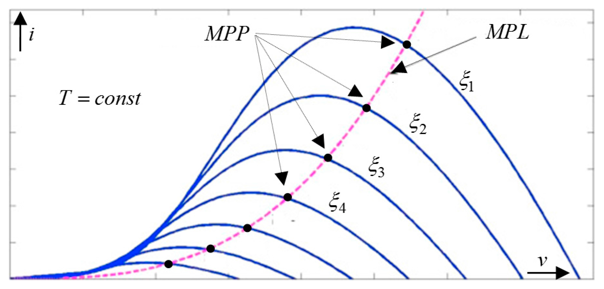
Figure 2.
Electrical side REG characteristics for different values of energy producing variable and corresponding MPL.
Figure 2.
Electrical side REG characteristics for different values of energy producing variable and corresponding MPL.

Figure 3.
Wind turbine generator under study.
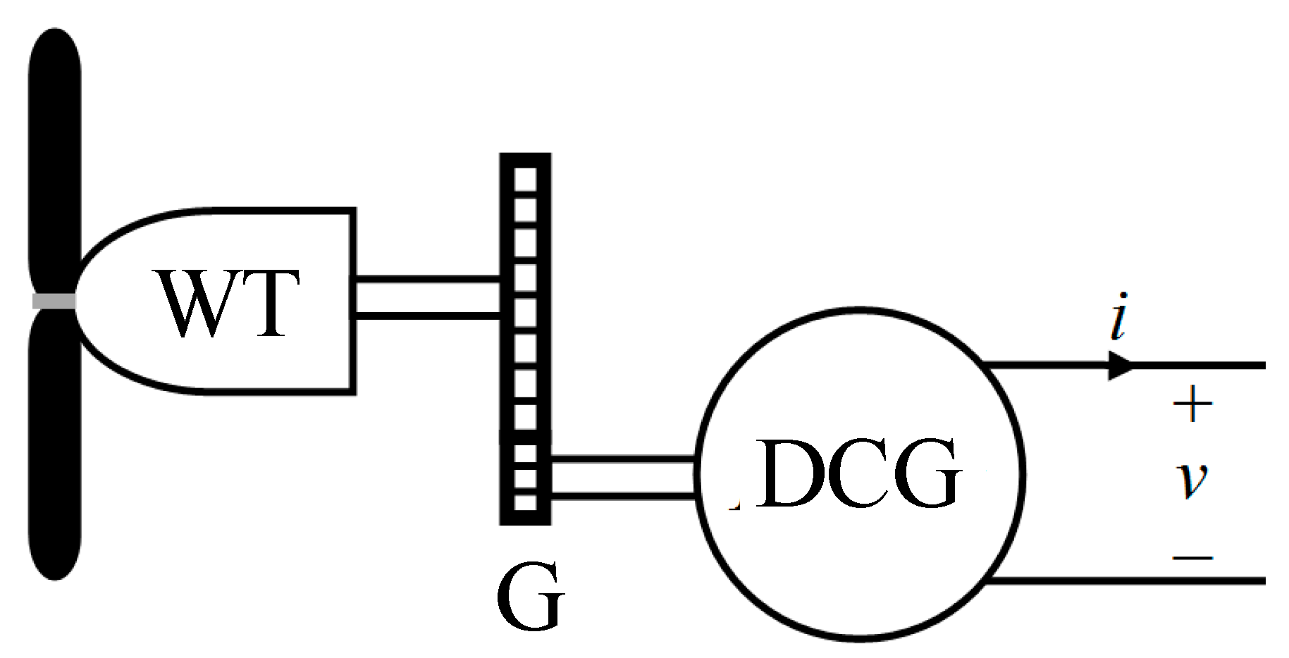
Figure 4.
Electrical side characteristics of the wind turbine generator (WTG)-DC generator (DCG) and MPLs calculated according to (17) and (18).
Figure 4.
Electrical side characteristics of the wind turbine generator (WTG)-DC generator (DCG) and MPLs calculated according to (17) and (18).

© 2017 by the authors. Licensee MDPI, Basel, Switzerland. This article is an open access article distributed under the terms and conditions of the Creative Commons Attribution (CC BY) license (http://creativecommons.org/licenses/by/4.0/).
Share and Cite
MDPI and ACS Style
Kolesnik, S.; Kuperman, A. Analytical Derivation of Electrical-Side Maximum Power Line for Wind Generators. Energies 2017, 10, 1498. https://doi.org/10.3390/en10101498
AMA Style
Kolesnik S, Kuperman A. Analytical Derivation of Electrical-Side Maximum Power Line for Wind Generators. Energies. 2017; 10(10):1498. https://doi.org/10.3390/en10101498
Chicago/Turabian StyleKolesnik, Sergei, and Alon Kuperman. 2017. "Analytical Derivation of Electrical-Side Maximum Power Line for Wind Generators" Energies 10, no. 10: 1498. https://doi.org/10.3390/en10101498
Note that from the first issue of 2016, this journal uses article numbers instead of page numbers. See further details here.