Optimization of Solar Water Heating System under Time and Spatial Partition Heating in Rural Dwellings

School of Environment and Municipal Engineering, Xi’an University of Architecture and Technology, Xi’an 710055, China
*
Author to whom correspondence should be addressed.
Energies 2017, 10(10), 1561; https://doi.org/10.3390/en10101561
Submission received: 10 September 2017
/
Revised: 23 September 2017
/
Accepted: 27 September 2017
/
Published: 11 October 2017
(This article belongs to the Special Issue Solar Technologies for Buildings)
Abstract
:This paper proposes the application of time and spatial partition heating to a solar water heating system. The heating effect and system performance were analyzed under the continuous and whole space heating and time and spatial partition heating using TRNSYS. The results were validated by comparing with the test results of the demonstration building. Compared to continuous and whole space heating, the use of time and spatial partition heating increases the solar fraction by 16.5%, reduces the auxiliary heating by 7390 MJ, and reduces the annual operation cost by 2010 RMB. Under time and spatial partition heating, optimization analyses were conducted for the two system capacity parameters of the solar collector area and tank volume and the one operation parameter of auxiliary heater setting outlet temperature. The results showed that a reasonable choice of the solar collector area can reduce the dynamic annual cost, the increased tank volume is advantageous to heat storage, and the auxiliary heater setting outlet temperature have greater influence on the indoor heating effect. The advanced opening of solar water heating system and the normal opening of passive air vents are recommended. Based on the comparison of the two modes, the time and spatial partition heating technology is a better choice for rural dwellings.
1. Introduction
With the increasing rate of urbanization in China, the requirements for indoor thermal environment have improved with the gradual improvement in resident living standards [1,2]. As a result, the energy consumed in rural buildings accounts for more than half of the total building energy consumption in recent years [3], in which the heating energy consumption accounted for a majority proportion. Most areas in Northwest China have abundant solar energy and possess solar heating conditions. Therefore, solar heating should be the priority development direction of building heating and energy saving.
In the present, many researchers have studied the solar water heating system (SWHS) and focused mainly on aspects such as system optimization, operation control analysis, and system evaluation [4,5,6]. The research of system optimization mainly includes the unit design parameters of different types of collectors [7,8,9], water tanks [10,11,12], heat exchangers [13,14], and system operating parameters [15,16,17]. The operation control can be divided into solar collecting and heating systems according to the control objectives. System evaluation is mainly divided into solar fraction [18] and economic analysis [19]. Marcos et al. [20] analyzed the thermal performances of SWHS of plate solar collector by experiment, and the results showed that the solar facility was able to meet 55% of the space heating demand. Zeghib and Chaker [21] established the theoretical model of solar heating to analyze the system performances. These research methods provided references for the optimization and performance analysis of SWHS. Presently, the solar heating technology has matured, and correspondingly the demonstration buildings were built in many areas [22,23]. Furthermore, the corresponding technical specifications and evaluation standards [24,25] were formed to provide the basis of engineering applications and constructions.
The SWHSs are ordinarily conventional heating mode [26], namely continuous and whole space heating (CWSH), in which the heat demand is huge in order to meet the heat requirements of all rooms. As a result, the system scale tended to be great, resulting in high initial investment [27,28,29]. On the contrary, if smaller SWHS was adopted, thus, the solar fraction would tend to be low with high auxiliary energy and running cost [30]. Martinopoulos and Tsaliki [31] showed that solar space heating systems have rather low levels of market penetration and public acceptance despite being a mature technology. Obviously, the higher investment cost of SWHS is a hindrance its popularization and application. In addition, the problems of poor indoor thermal environment and low solar fraction [32] still exist due to lack of scientific operation management. It is the key to propose a rational heating mode for improving the application of SWHS.
Badran et al. [33] illustrated that the intermittent heating could effectively reduce the fuel. Shen [34] compared the local heating simulation of different rooms and found that the intermittent heating could effectively reduce the heating load. It is an effective way to reduce the energy supply of solar system while the intermittent or local heating mode was adopted in solar buildings.
In Northwest China, the indoor activities of rural residents during different periods are relatively concentrated to some fixed rooms [35]. In addition, relative researches showed that persons tend to have different thermal requirements under active and sleeping conditions [36,37]. Therefore, the heating mode can adopt not only the intermittent heating, but also local heating with differences of design temperature. Thus, it is feasible to propose a new heating system that provides heat via different time, space, and design temperature alternatives in rural areas of Northwest China.
While the intermittent or local heating was adopted, the hourly energy demand varies greatly, which would influence the operation of system and heat storage. As a result, the SWHS was affected and varied. However, the study of intermittent and local heating in the solar system is rare, especially when the two heating systems exist simultaneously.
A demonstration building of solar heating in Northwest China was considered as the research object, the main objectives of this paper include the following four parts: (1) A time and spatial partition heating (TSPH) mode was proposed for the SWHS based on the indoor activity trajectory and differences of heat demand in winter in rural areas of Northwest China. (2) The TRNSYS simulation models of TSPH and CWSH were established and the accuracy of the simulation models was validated through an indoor thermal-environment test and system performance analysis. The application feasibility of TSPH was analyzed by comparing the indoor heating effect and system performance. (3) Considering that TSPH and CWSH differ in system thermal performance, the influences of design parameters and operating parameters on the indoor heating effect and system performance were analyzed. (4) The influence of active and passive system operation strategies on the indoor heating effect and system performance is discussed; this could provide the basis for the application of TSPH of a solar system in a rural building.
2. Demonstration Project and Analysis Approach
2.1. Demonstration Project
The solar heating demonstration project is located in Gangcha County, Qinghai Province (100°08′ E, 37°20′ N), with total areas of 9360 m2. Combined active and passive (attached sunspace and Trombe wall) solar heating technologies were adopted. We take one building as the investigated objective, with an area of 72 m2. Figure 1 shows the layout.
2.1.1. Passive Solar Building
In reality, only three rooms need space heating: the second bedroom (SB), master bedroom (MB), and living room (LR). Thus, the heating area is only 50.04 m2. Table 1 lists the thermo-physical property parameters of the building envelope surfaces of the passive house according to the detailed building structures. All the windows adopt a plastic steel material with 4-mm glass. Table 2 lists the components of the passive solar houses.
2.1.2. Solar Water Heating System
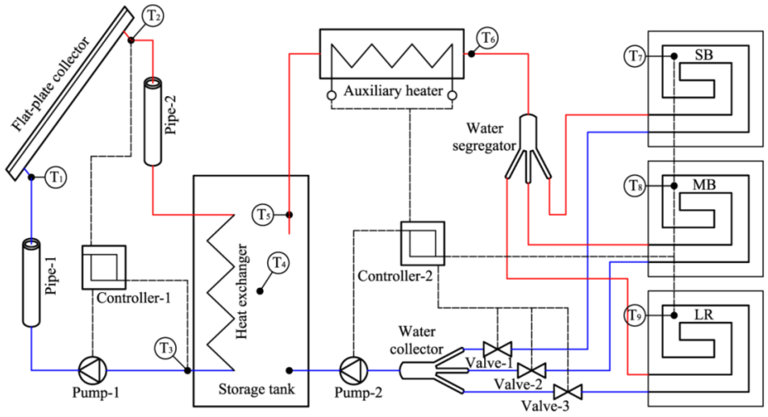
Figure 2 shows the schematic of the SWHS, which was designed for the heating of the demonstration building. The solar system has 7 flat-plate collectors with a total area of 14 m2, and the slope of each collector surface is 45°. A vertical cylindrical heat storage tank (0.9 m height × 0.54 m diameter) was adopted, located in the toilet with one inner heat exchanger (the overall heat transfer coefficient UA = 37.1 W/m·K). The auxiliary heater with a rated power of 3 kW is in series with the water-supplied side of the heating system. The diameter of the transportation pipeline is DN25, and the pipeline is wrapped in a 20-mm-thick thermal insulation material made of high-expansion polyethylene. The SWHS includes a circulating pump for the solar collector system, circulating pump for the heating system, water segregator, water collector, controller, and floor heating system. A floor heating system was used with a DN15 pipe and 300 mm pipe spacing.
2.2. Time and Spatial Partition Heating Mode
According to the activity trajectories and differences of heat demand of residents in winter in rural areas of Northwest China [35], a new heating mode was proposed in this paper, namely time and spatial partition heating (TSPH), to reduce the system scale, initial investment and running cost. Thus, the improvement of solar fraction was achieved.
TSPH was defined as a heating mode that had different time, space, and design temperature alternatives according to the activity trajectories and differences of heat demand of residents in winter in rural areas of Northwest China. It contained following two parts: (a) there is similar indoor activity trajectories in winter [35], thus, only the space occupied with persons was heated to realize the differences of heating in time and space, namely, the living room was heated in the daytime while the bedroom was heated in the night-time; (b) humans had different heat demand in various conditions, so the design temperature was dependent on the heat requirement, that is, the comfort temperature is 18 °C [38] in active conditions, while 12 °C [39] should be the comfort temperature in sleeping conditions.
As for the demonstration building, there were three function rooms which adopted CWSH. According to the features of TSPH, the design temperature was re-set. The heating periods and design temperatures in the three rooms for both the modes were listed in Table 3.
Control strategy and control parameters of TSPH are shown in Figure 3a. There are different heating time and design temperature according to the different functions. In the control process, the heating time is the first element to be judged. Then, the design temperature of each function room was determined. The master bedroom was heated the whole day, but the design temperature was different in the daytime and nighttime; the living room was heated in the daytime to a temperature of 18 °C; the second bedroom was heated in the night to a temperature of 12 °C. Whether the three indoor temperatures met the requirements determined whether the auxiliary heater was open or closed. The control system and control parameters of CWSH are shown in Figure 3b. The rooms were continuously heated and the temperature was set to 18 °C in 24 h for a day [40].
2.3. System Thermal Performance and Economic Analysis
For the short-term heat storage in a SWHS, its heat-storage capacity and tank volume are determined according to the heat consumption of a building and the useful energy gain of a solar collector system. The heat consumption of a building with WCSH and TSPH are calculated using Equations (1) and (2), respectively:
where Qload is the heat consumption of the building, j is the serial number of functional rooms, and n = x + y + z is total number of functional rooms; x, y, and z are the number of functional rooms with heating for an entire day, in the daytime, and at night, respectively.
where Qsolar is the useful energy gain of the solar collector system, cp represents the specific heat of water, and m is the mass flow of the solar collector system.
The useful energy gain of the solar collector system is calculated by
where Ac is the solar collector area, ILa is the total tilted surface solar radiation, and η is the collector efficiency.
where Qaux, Paux, and taux represent the auxiliary heating, rated power, and operation hours of the auxiliary electric heater, respectively.
The solar fraction f of the SWHS is calculated by
Therefore, the heat storage changes inevitably with heating-mode switching; this puts forward a new requirement for the tank volume. This in turn influences the heat-storage medium parameters and the useful energy gain of the solar collector system. In addition, the auxiliary heating and solar fraction will be affected directly.
To compare the economic system of the two heating modes, dynamic analysis is used according to the dynamic annual cost method. The economic model formula is as follows [41]:
where COSTy, COSTini, and COSTop are the dynamic annual cost, initial investment cost, and annual operation cost, respectively. Furthermore, i is the bank loan interest rate assumed to be 4.9% [42], n is the service life of SWHS and is assumed to be 15 years [43].
The power consumption of an auxiliary electric heater is calculated as follows:
where ELEaux is the power consumption of the auxiliary electric heater and ηele indicates the rated power of the auxiliary electric heater. Thus, the annual operation cost is calculated as follows:
where pele is the electricity price assumed to be 0.93 RMB/kWh [44], ELEpump is the pumps’ power consumption, which can be ignored compared to the power consumption of the auxiliary electric heater, and Cm is the annual maintenance cost.
3. TRNSYS Modeling and Validation
3.1. Thermal Performance Simulation Model
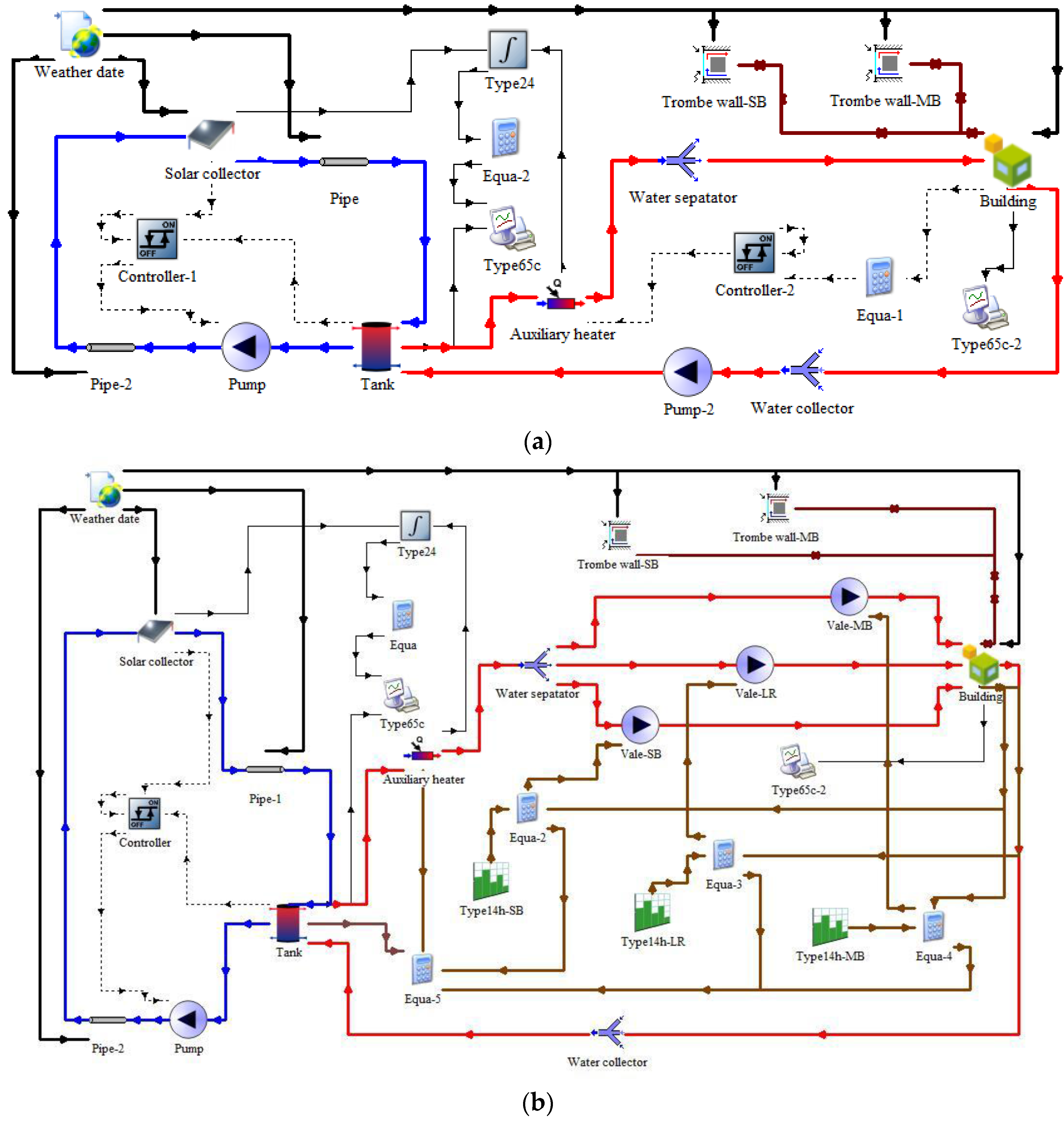
In this study, the SWHS simulation model with CWSH and TSPH developed using TRNSYS17.1 [45] was established, as shown in Figure 4a,b. Differences exist between the control of the TSPH and CWSH systems; the logical diagram is shown in Figure 3a,b. As the demonstration buildings are of the same size, one was selected as a physical model and built using Google SketchUp based on Section 2.1.1, and then imported into TRNBuild for parameter settings as an external file for Type 56. It is assumed that the partitions of the two dwellings were insulated. Active layers in the floor were only set in the MB, SB, and LR. Table 4 lists the main components and parameters of TRNSYS modeling.
3.2. Tests and Model Validation
3.2.1. Dynamic Thermal Performance Tests
In the demonstration project, one dwelling with a SWHS was taken as the research object. The outdoor meteorological conditions, heating effect, and system performance of the SWHS were measured in the testing of the demonstration building by using CWSH during 23–28 April in 2016. The main parameters of the test include the global solar irradiance on the inclined collector and horizontal surfaces, ambient temperature, indoor air temperature of the three functional rooms, inlet and outlet temperatures of each component, and mass flow of each system. The opening and closing time of each valve, start and stop time of the auxiliary heating equipment, and power consumption were also recorded. The time interval for data acquisition was 10 min.
3.2.2. Model Validation
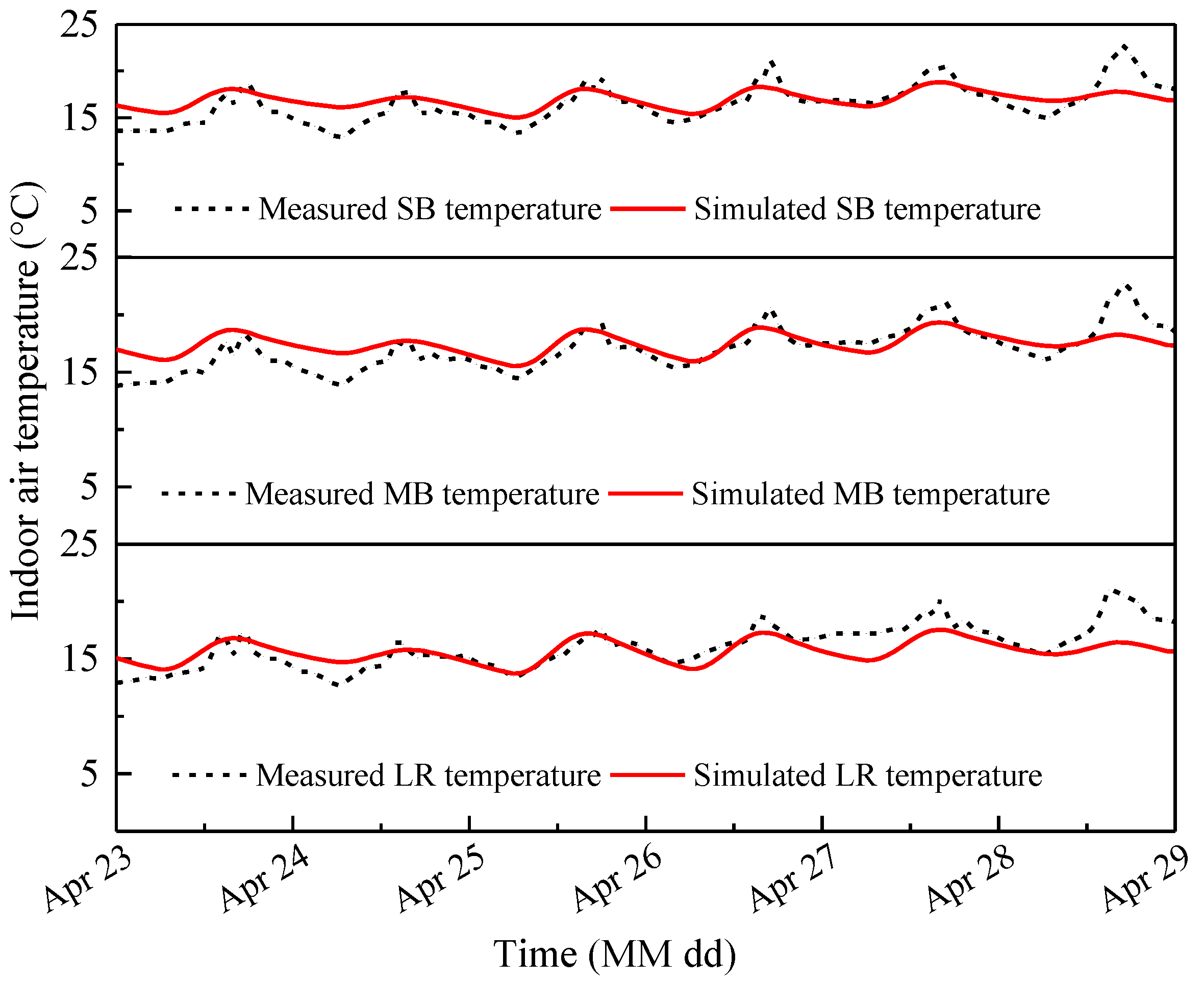
In order to guarantee the accuracies of model validations, the meteorological data tested during experiments were used as the input file in type 99 instead of the TMY data in TRNSYS. The initial temperature and charge status of the tank and heat storage have an important influence on the simulation results [46]. The initial temperature of tank was assumed to be 10 °C according to the tap water temperature in Qinghai. To eliminate the influences of initial temperature of heat storage tank and initial thermal inertia of the building on the simulation results, meteorological conditions for a month (every day was the same as 23 April) were added to the input data before the beginning of field test [40]. The simulated time step was 10 min, which was the same as that of the test data. The simulation data during the test was outputted for comparison with the test data. Figure 5 shows the simulated and test data for the indoor air temperature of the three rooms. It can be seen that the whole trend is close in both cases, although local deviations exist between them. The test and simulation results showed that the average relative error of indoor air temperature in the three rooms is 6.9%. The initial and final stages during the test period were observed to be the most different; this might be due to the following reasons: the on/off operation time of the air vents of the Trombe wall was not set, the actual amount of cold air penetration in the room was considerable because of the movement of the residents and testers in and out of the room, or other reasons.
Table 5 lists the comparison of the simulation results and the field test data of the system’s thermal performance. This comparison includes the calculation of the following three parameters during the test: useful energy gain, auxiliary heating, and solar fraction. It was determined that the relative errors of the accumulated heat energy collected by the solar system and the solar fraction are within 6%. In addition, the relative error of the accumulated heat energy provided by the electric heater is −12.7%. The auxiliary heating during the test is higher than in the simulation results; this may be because the recording of the electricity during the test also includes domestic lighting and the operation of the recording instrument. The simulation results show that the calculation error can be accepted, suggesting that the simulated model is reasonable for the following analysis.
4. Results and Discussion
4.1. System Comparison with Two Heating Modes
4.1.1. Heating Effect
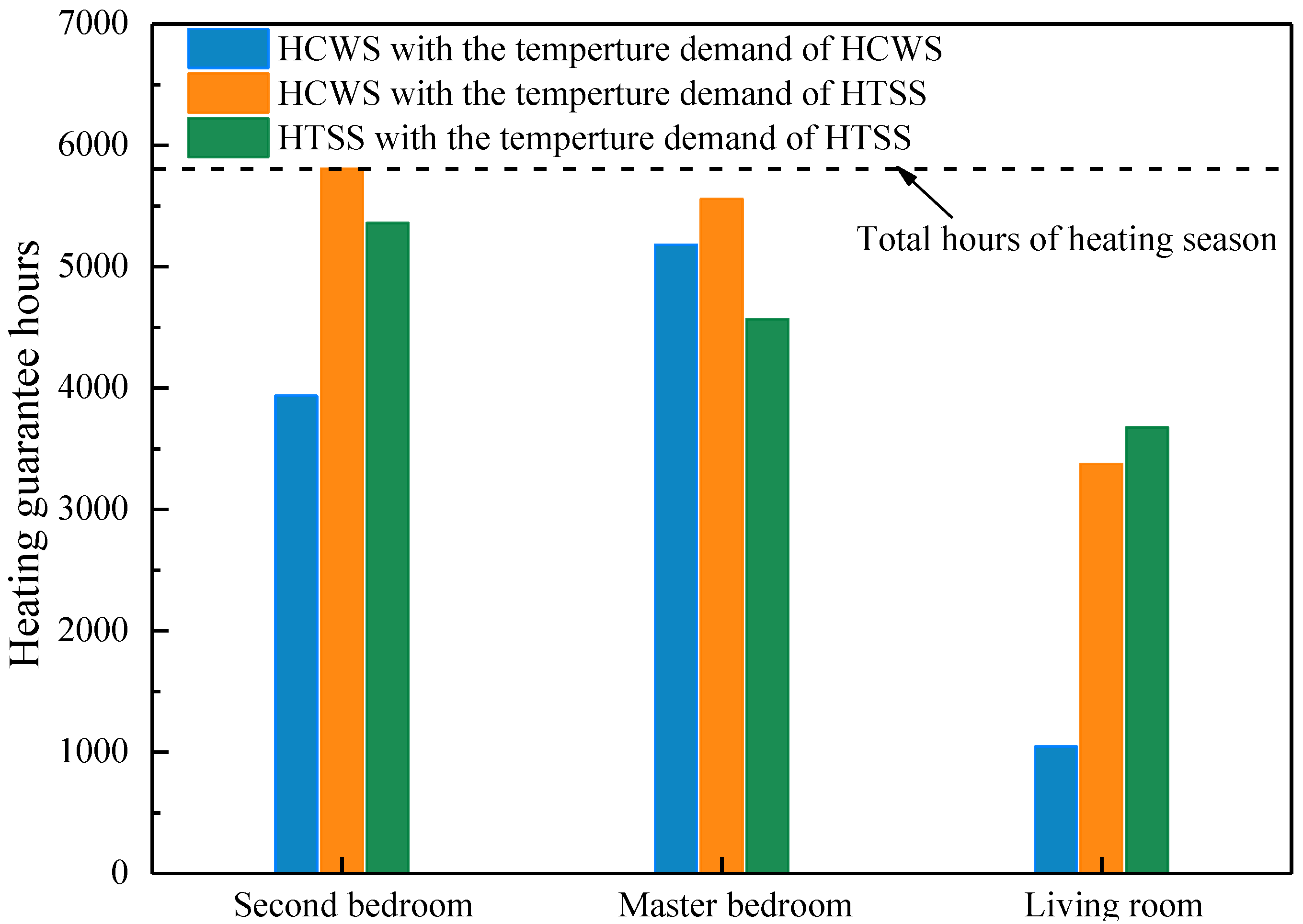
The indoor air temperature of three rooms in the two modes during the heating season was simulated using TRNSYS, and compared with the heating design temperature in Table 3. The room temperature is guaranteed when it is higher than the heating design temperature. The heating guaranteed hours of the three functional rooms under different heating modes and human thermal requirements are shown in Figure 6. It can be seen that the LR indoor air temperature was difficult to guarantee. The guaranteed hours of CWSH were higher than TSPH only in the MB, mostly because the LR temperature was difficult to guarantee even when the auxiliary heating equipment was running at rated power and the heating requirements of the TSPH system was relatively small. The heating design temperature of CWSH could not be met under the conditions of CWSH, but can comfortably meet the temperature requirements. Although the heating guaranteed hours of TSPH were lower than under CWSH, they met the heating design temperature to a large extent. Furthermore, when the indoor air temperature under the TSPH conditions could not meet the heating design temperature of TSPH, the average temperature of the three rooms was only −0.5 °C, −1.4 °C, and −2.2 °C lower than that in CWSH, respectively. Therefore, the heating effect of TSPH is mostly acceptable.
4.1.2. System Performance Evaluation
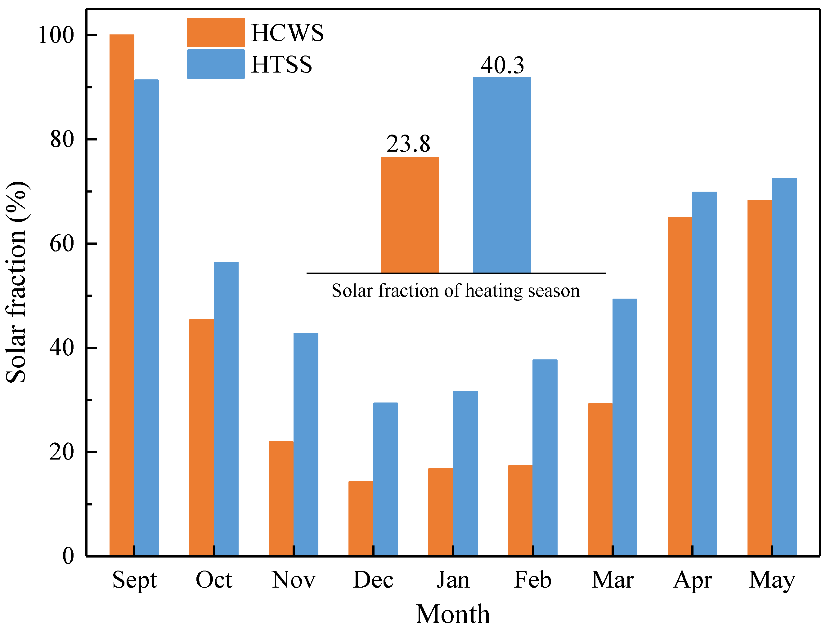
Auxiliary heating, solar fraction, and dynamic annual cost obtained by simulation were selected as the system performance evaluation analysis indicators. The monthly average solar fraction of the two models during the heating season is shown in Figure 7.
In addition to 23–30 September, the solar fraction improved in TSPH, especially during months from November to March. The effective energy gain of the solar collector system can meet the heating design temperature of CWSH owing to higher solar radiation intensity and higher outdoor temperature in September. In TSPH, the preheat load was large while the instantaneous heat supply was insufficient, resulting in decreased fraction. The solar fraction can increase by 16.5% in TSPH compared with CWSH. This is because of the fewer heating time and the lower heating design temperature.
Auxiliary heating in the two heating modes is presented in Table 6. It shows that TSPH can effectively reduce auxiliary heating, especially in low outdoor air temperature. Compared with CWSH, auxiliary heating in TSPH can be reduced by 7390 MJ in the entire heating season. Taking only the difference in the heating mode in the same SWHS into account, the initial investment cost was the same for the two heating modes. Therefore, the operating cost of the TSPH system can be reduced by 2010 RMB combined with the CWSH. The guaranteed hours of heating slightly reduced and the operating costs significantly reduced in TSPH compared with the CWSH. Therefore, it is feasible to use SWHS with TSPH for rural buildings with different heating demands.
4.2. System Optimization of TSPH
The above analysis shows that TSPH is suitable to meet indoor temperature requirements and increase solar fraction. However, there are still some periods in which it could not meet the heating design temperature. SWHS was designed in CWSH, and not in TSPH. Therefore, the optimization of the solar collector area, tank capacity, and one operating parameter of the auxiliary heater setting outlet temperature of the two systems were accomplished under TSPH condition on the basis of the current system.
4.2.1. Solar Heating Area
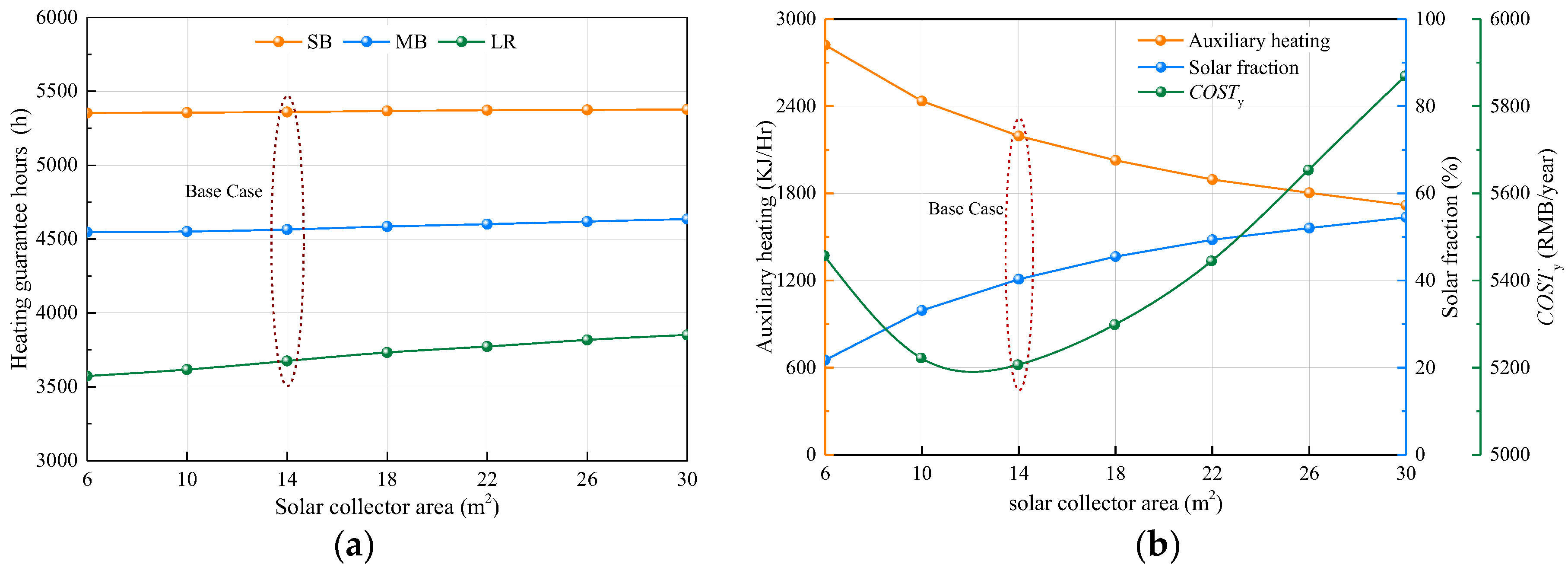
Figure 8 shows the optimized analysis of different solar collector areas. The heating guaranteed hours showed an increasing trend when the solar collector area increased. The increase in the heating guaranteed hours in the LR was the most obvious, while the SB remained unchanged. The increase in the solar collector area resulted in an increase in the water supply temperature in the water tank and instantaneous heating capacity. With the increase in the solar collector area, auxiliary heating was reduced and solar fraction increased, while the change rate was gradually reduced. It can be observed that blindly increasing the solar collector area was not a reasonable choice. When the solar collector area was 10–14 m2, the most cost effective option was achieved and the heating guaranteed hours can also be met to a certain extent. Appropriate reduction in the solar collector area favored the operation of TSPH compared with SWHS with CWSH.
4.2.2. Tank Volume
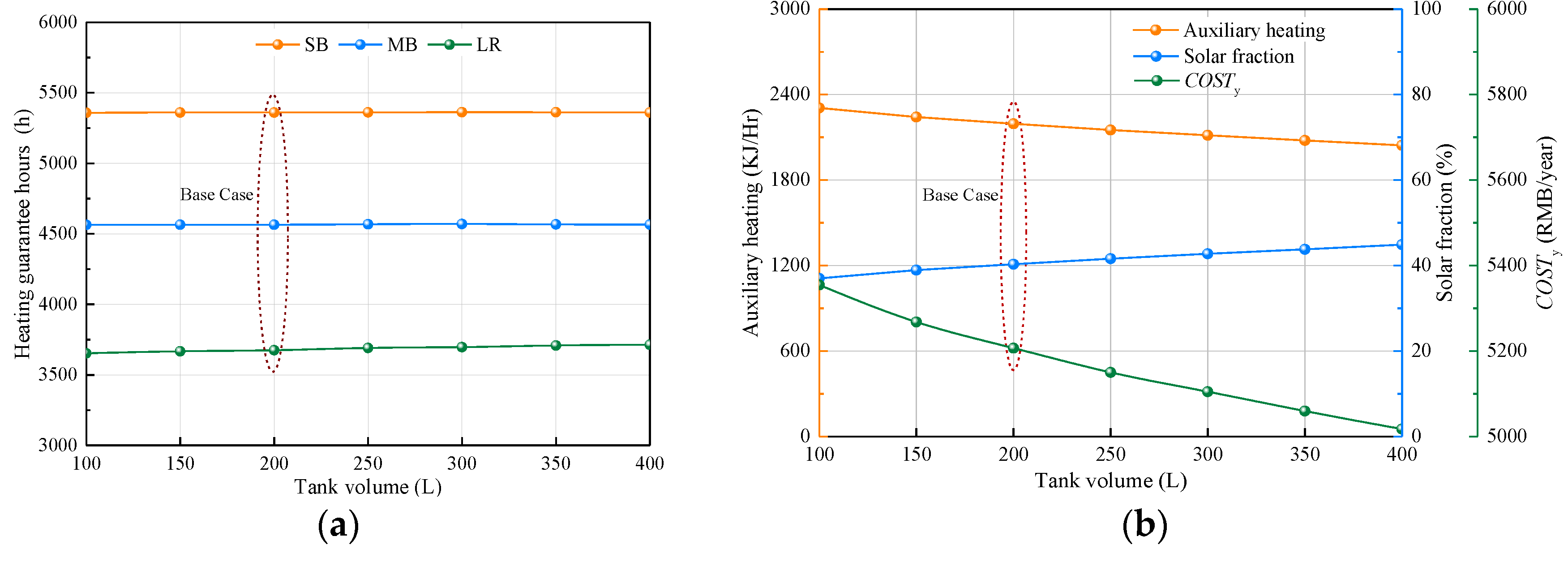
As shown in Figure 9, the heating effect and system performance were analyzed for varying tank volumes. The change in the tank volume had minor influence on the heating effect owing to minor influence on the heat source. The heating guaranteed hours of SB and MB first decreased and then increased, while that of LR slowly increased. The increase in the tank volume directly resulted in the decrease in the heat storage temperature, and increase in the heat storage capacity. For the SB and MB, the increase in the heat storage capacity had less influence on the guaranteed hours, which reached a high degree with continuous heating. Owing to a decrease in the heat storage temperature capacity, instantaneous heating supply will lead to a reduction in the guaranteed hours at the initial heating stage.
Solar fraction slowly increased and auxiliary heating and annual calculation cost gradually decreased owing to an increase in the tank volume. During the early heating season, the required heat supply of the building and the consumption of useful energy gain were low, which resulted in the use of a larger tank for heat storage. It can be seen that the tank temperature at the initial and final stage of the heating season was significantly higher than that at the middle stage. Therefore, compared with the CWSH, the tank heat storage temperature decreased, the system effective heat collection improved [47], and the heat storage in the initial heating season increased owing to an increase in the tank volume, which favored the operation of SWHS with TSPH.
4.2.3. Auxiliary Heater Setting Outlet Temperature
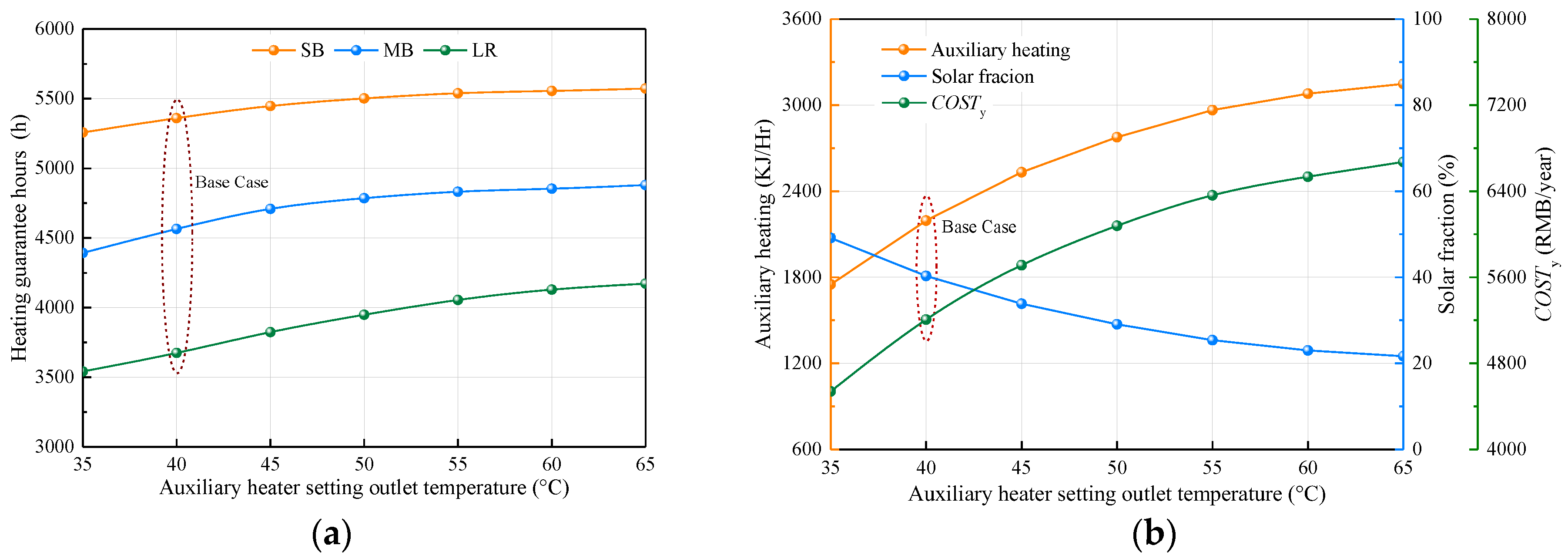
The influence of the auxiliary heater setting outlet temperature on the heating effect and system performance is shown in Figure 10. The auxiliary heater setting outlet temperature had a great influence on the heating effect and system performance, while the influence gradually decreased when the temperature was higher than 50 °C. The increase in the auxiliary heater setting outlet temperature will cause a significant increase in working time, especially when the tank temperature was insufficient in the middle of the heating season. This will increase the tank temperature, reduce the useful energy gain, and solar fraction significantly. Higher auxiliary heater outlet setting temperature can increase system instantaneous heat capacity and heating guaranteed hours, but will also increase auxiliary heating capacity and system operating costs. Therefore, by choosing the stage in which the increase in the heating guaranteed hours slowed down, the lowest dynamic annual cost corresponding to the most reasonable auxiliary heater setting outlet temperature can be achieved.
In summary, the smaller the solar collector area, the larger the tank volume, and the higher the auxiliary setting outlet temperature favorable for the operation of SHWS with TSPH compared with the CWSH. In addition, in the function rooms, such as the LR with obvious intermittent period and higher indoor heating design temperature during the heating season, the heating guaranteed hours were always at low levels under TSPH conditions. In future studies, we will consider how to enhance the heating effect of this type of function rooms.
4.3. Discussion of Optimal Operation of Active and Passive System
Based on the analysis above, a reasonable selection of system design capacity and operating parameters setting favor the operation of SWHS with TSPH. In addition, since the instantaneous heating of TSPH is not synchronized with the required heat supply, we can also optimize the on/off operation time of the active and passive systems.
4.3.1. On/Off Operation Time of SWHS
The heating effect and system performance of the on/off operation time of SWHS is presented in Table 7. Except for the SB, advanced opening of SWHS significantly increased the heating guaranteed hours of the MB and LR. The existence of the Trombe wall enabled the SB indoor air temperature to meet the requirements of 12 °C at 22:00 in most stages of the heating season. The system heat storage capacity will transfer to another two rooms while the SWHS opening time advanced, resulting in insufficient tank storage energy and shortened heating guaranteed hours.
The increase in the heating time can significantly improve the MB and LR heating guaranteed hours, but will increase auxiliary heating and reduce solar fraction. By comparing the amplification of both auxiliary heating and heating guaranteed hours in the simulated cases and the base case, it can be seen that an increase in the heating time was not favorable to the operation of SWHS. Furthermore, there is an optimal time for opening the active system.
4.3.2. On/Off Operation Time of Trombe Wall
It is necessary to discuss the on/off operation time of the Trombe wall because the opening and closing of air vents have a great impact on the passive heat gain for the room [48]. The simulation results are presented in Table 8. It can be seen that the closing of air vents was not favorable to the operation of TSPH, and will reduce passive heat gain during the daytime, which contradicts the high heat consumption of the building. Opening the air vents was not only favorable to enhance the heating guaranteed hours, but also to reduce auxiliary heating. The temperature differential control of the Trombe wall not only increased the heating guaranteed hours, but also reduced auxiliary heating and increased solar fraction to a great extent. However, this temperature differential control of the Trombe wall in the operation was cumbersome, which is not suitable for engineering applications. Therefore, the normal opening of the passive air vents is recommended when the Trombe wall is not properly managed.
5. Conclusions
This paper proposes the application of a TSPH to a SWHS. The heating effect and system optimization under TSPH were investigated using experiments and numerical simulations. The conclusions drawn from the results are stated as follows:
- (1)
- The indoor heating effect and system performance evaluation were analyzed with CWSH and TSPH by means of TRNSYS dynamic simulation software. The results were validated by comparison with the test results of a demonstration building using CWSH in the period of 23–28 April. It was found that the average relative error in the temperature of the three rooms was 6.9%, and the relative errors of the accumulated heat energy collected by the solar system and solar fraction were within 6%.
- (2)
- The indoor air temperature of TSPH was already satisfied to a great extent, although the heating guaranteed hours with TSPH was lower than with CWSH. Compared with CWSH, solar fraction can be increased by 16.5%, auxiliary heating during the heating season can be reduced by 7390 MJ, and the annual operation cost can be reduced by 2010 RMB, with TSPH. Therefore, time and spatial partition solar heating technology was a better option for rural residence.
- (3)
- The indoor heating effect and solar fraction can improve if the solar collector area increased. When the solar collector area was 10–14 m2, the dynamic annual cost could be reduced to lower than 5200 RMB. Increased tank volume is advantageous for heat storage. The auxiliary heater setting outlet temperature had greater impact on the indoor heating effect, and this influence weakened when the auxiliary heater setting outlet temperature was higher than 50 °C.
- (4)
- Advanced opening and closing with 2 h of SWHS and increased heating time could improve the guaranteed hours of MB and LR. Increasing the heating time was unfavorable to system performance, and there were a suitable number of hours for advanced opening of SWHS. Closing of air vents hindered heat gain of the Trombe wall.
Acknowledgments
This work was supported by the national key research projects (No. 2016YFC0700400) and the National Natural Science Foundation of China (No. 51378411 and No. 51678468).
Author Contributions
Yanfeng Liu has contribution on the literature search and study design; Tao Li has contribution on the literature search, data collection and manuscript writing; Yaowen Chen has contribution on the simulation and figures design; Dengjia Wang has contribution on the test design and data collection.
Conflicts of Interest
The authors declare no conflict of interest.
Nomenclature
| Ac | solar collector area (m2) |
| cp | specific heat of the water (kJ/kg·°C) |
| Cm | annual maintenance cost (RMB) |
| COSTini | initial investment cost (RMB) |
| COSTop | annual operation cost (RMB) |
| COSTy | dynamic annual cost (RMB/Year) |
| ELEaux | power consumption of auxiliary electric heater (kW h) |
| ELEpump | power consumption of pump (kW h) |
| f | solar fraction (%) |
| i | bank loan interest rate (%) |
| ILa | total tilted surface solar radiation (kJ/Hr·m2) |
| m | mass flow of solar collector system (kg/Hr) |
| n | service life of SWHS (Year) |
| pele | electricity price (RMB/kW h) |
| Paux | rated power of auxiliary electric heater (W) |
| Qaux | auxiliary heating energy (kJ) |
| Qsolar | useful energy gain of solar collector system (kJ) |
| Qload | heat consumption of the building (kJ) |
| taux | operation hours of auxiliary electric heater (h) |
| Ta | outdoor air temperature (°C) |
| Tair | indoor air temperature (°C) |
| Tair,L | temperature of air layer (°C) |
| T1 | outlet temperature of solar collector system (°C) |
| T2 | inlet temperature of solar collector system (°C) |
| T3 | temperature to heat source of tank(°C) |
| T4 | temperature of tank (°C) |
| T5 | temperature to load of tank (°C) |
| T6 | outlet temperature of auxiliary electric heater (°C) |
| T7 | indoor air temperature of second bedroom (°C) |
| T8 | indoor air temperature of master bedroom (°C) |
| T9 | indoor air temperature of living room (°C) |
| Greek Letters: | |
| η | collector efficiency (%) |
| ηele | thermal efficiency of auxiliary electric heater (%) |
| Subscripts: | |
| all | heating in the whole day |
| day | heating in the daytime |
| j | number of functional room |
| n | total number of functional rooms |
| night | heating in the nighttime |
| x | total number of functional rooms with heating in the daytime |
| y | total number of functional rooms with heating in the whole day |
| z | total number of function rooms with heating in the nighttime |
| Abbreviations: | |
| CWSH | continuous and whole space heating |
| LR | living room |
| MB | master bedroom |
| SB | second bedroom |
| SWHS | solar water heating system |
| TRNSYS | transient systems simulation program |
| TSPH | time and spatial partition heating |
References
- Li, J.P.; Li, X.Z.; Wang, N.; Hu, Y.Y.; Feng, R. Experimental research on indoor thermal environment of new rural residence with active solar water heating system and external wall insulation. Appl. Therm. Eng. 2016, 95, 35–41. [Google Scholar] [CrossRef]
- Lin, B.R.; Wang, Z.; Liu, Y.C.; Zhu, Y.X.; Ouyang, Q. Investigation of winter indoor thermal environment and heating demand of urban residential buildings in China’s hot summer—Cold winter climate region. Build. Environ. 2016, 101, 9–18. [Google Scholar] [CrossRef]
- Evans, M.; Yu, S.; Song, B.; Deng, Q.Q.; Liu, J.; Delgado, A. Building energy efficiency in rural China. Energy Policy 2014, 64, 243–251. [Google Scholar] [CrossRef]
- Shukla, R.; Sumathy, K.; Erickson, P.; Gong, J.W. Recent advances in the solar water heating systems: A review. Renew. Sustain. Energy Rev. 2013, 19, 173–190. [Google Scholar] [CrossRef]
- Wang, Z.Y.; Yang, W.S.; Qi, F.; Zhang, X.M.; Zhao, X.D. Solar water heating: From theory, application, marketing and research. Renew. Sustain. Energy Rev. 2015, 41, 68–84. [Google Scholar] [CrossRef]
- Jamar, A.; Majid, Z.A.A.; Azmi, W.H.; Norhafana, M.; Razak, A.A. A review of water heating system for solar energy applications. Int. Commun. Heat Mass Transf. 2016, 76, 178–187. [Google Scholar] [CrossRef]
- Subiantoro, A.; Ooi, K.T. Analytical models for the computation and optimization of single and double glazing flat plate solar collectors with normal and small air gap spacing. Appl. Energy 2013, 104, 392–399. [Google Scholar] [CrossRef]
- Nkwetta, D.N.; Smyth, M.; Zacharopoulos, A.; Hyde, T. Experimental performance analysis and optimisation of medium temperature solar thermal collectors with silicon oil as a heat transfer fluid. Int. J. Energy Res. 2013, 37, 570–581. [Google Scholar] [CrossRef]
- Liang, R.B.; Ma, L.D.; Zhang, J.L.; Zhao, D. Theoretical and experimental investigation of the filled-type evacuated tube solar collector with U tube. Sol. Energy 2011, 85, 1735–1744. [Google Scholar] [CrossRef]
- Fan, J.H.; Furbo, S. Thermal stratification in a hot water tank established by heat loss from the tank. Sol. Energy 2012, 86, 3460–3469. [Google Scholar] [CrossRef]
- Çomaklı, K.; Çakır, U.; Kaya, M.; Bakirci, K. The relation of collector and storage tank size in solar heating systems. Energy Convers. Manag. 2012, 63, 112–117. [Google Scholar] [CrossRef]
- Furbo, S.; Knudsen, S. Improved design of mantle tanks for small low flow SDHW systems. Int. J. Energy Res. 2006, 30, 955–965. [Google Scholar] [CrossRef]
- AL-Khaffajy, M.; Mossad, R. Optimization of the heat exchanger in a flat plate indirect heating integrated collector storage solar water heating system. Renew. Energy 2013, 57, 413–421. [Google Scholar] [CrossRef] [Green Version]
- Miao, X.Y.; Zheng, T.Y.; Görke, U.J.; Kolditz, O.; Nagel, T. Thermo-mechanical analysis of heat exchanger design for thermal energy storage systems. Appl. Therm. Eng. 2017, 114, 1082–1089. [Google Scholar] [CrossRef]
- Zainine, M.A.; Mezni, T.; Dakhlaouia, M.A.; Guizanid, A. Energetic performance and economic analysis of a solar water heating system for different flow rates values: A case study. Sol. Energy 2017, 147, 164–180. [Google Scholar] [CrossRef]
- Diego-Ayala, U.; Carrillo, J.G. Evaluation of temperature and efficiency in relation to mass flow on a solar flat plate collector in Mexico. Renew. Energy 2016, 96, 756–764. [Google Scholar] [CrossRef]
- Mazarrón, F.R.; Porras-Prieto, C.J.; García, J.L.; Benavente, R.M. Feasibility of active solar water heating systems with evacuated tube collector at different operational water temperatures. Energy Convers. Manag. 2016, 113, 16–26. [Google Scholar] [CrossRef]
- Domínguez-Muñoz, F.; Cejudo-López, J.M.; Carrillo-Andrés, A.; Ruivo, C.R. Design of solar thermal systems under uncertainty. Energy Build. 2012, 47, 474–484. [Google Scholar] [CrossRef]
- Gautam, A.; Chamoli, S.; Kumar, A.; Satyendra, S. A review on technical improvements, economic feasibility and world scenario of solar water heating system. Renew. Sustain. Energy Rev. 2017, 68, 541–562. [Google Scholar] [CrossRef]
- Marcos, J.D.; Izquierdo, M.; Parra, D. Solar space heating systems using high efficiency flat plate collectors: Experimental results. In Proceedings of the International Conference on Solar Heating, Graz, Austria, 28 September–1 October 2010. [Google Scholar]
- Zeghib, I.; Chaker, A. Modeling and simulation of a solar thermal system for domestic space heating using radiators low temperature. Int. J. Renew. Energy Res. 2015, 5, 266–276. [Google Scholar]
- Yu, Z.; Ji, J.; Sun, W.; Wang, W.; Li, G.Q.; Cai, J.Y.; Chen, H.F. Experiment and prediction of hybrid solar air heating system applied on a solar demonstration building. Energy Build. 2014, 78, 59–65. [Google Scholar] [CrossRef]
- Zheng, R.C.; Yin, Z.Q. 10-Solar thermal heating and cooling in China. Renew. Heat. Cool. 2016, 221–239. [Google Scholar]
- Standards China. Evaluation Standard for Solar Water Heating System of Civil Buildings; GB/T 50604-2010; China Building Industry Press: Beijing, China, 2012. (In Chinese) [Google Scholar]
- Zheng, R.C.; Lu, B.; Li, Z.; He, T. Technical Handbook for Solar Heating; China Building Industry Press: Beijing, China, 2012. (In Chinese) [Google Scholar]
- Badescu, V. Case study for active solar space heating and domestic hot water preparation in a passive house. J. Renew. Sustain. Energy 2011, 3, 3–11. [Google Scholar] [CrossRef]
- Tsaliki, G.; Martinopoulos, G. Solar energy systems potential for nearly net zero energy residential buildings. Sol. Energy 2015, 115, 743–756. [Google Scholar] [CrossRef]
- Marcos, J.D.; Izquierdo, M.; Parra, D. Solar space heating and cooling for Spanish housing: Potential energy savings and emissions reduction. Sol. Energy 2011, 85, 2622–2641. [Google Scholar] [CrossRef]
- Şerban, A.; Bărbuţă-Mişu, N.; Ciucescu, N.; Paraschiv, S.; Paraschiv, S. Economic and Environmental Analysis of Investing in Solar Water Heating Systems. Sustainability 2016, 8, 1286. [Google Scholar] [CrossRef]
- Glembin, J.; Haselhorst, T.; Steinweg, J.; Föste, S.; Rockendorf, G. Direct integration of solar heat into the space heating circuit. Sol. Energy 2016, 131, 1–20. [Google Scholar] [CrossRef]
- Martinopoulos, G.; Tsaliki, G. Active solar heating systems for energy efficient buildings in Greece: A technical economic and environmental evaluation. Energy Build. 2014, 68, 130–137. [Google Scholar] [CrossRef]
- Zheng, R.C.; Han, A.X. The present situation and development of solar heating technology in China. Constr. Sci. Technol. 2013, 1, 12–16. (In Chinese) [Google Scholar]
- Badran, A.A.; Jaradat, A.W.; Bahbouh, M.N. Comparative study of continuous versus intermittent heating for local residential building: Case studies in Jordan. Energy Convers. Manag. 2013, 65, 709–714. [Google Scholar] [CrossRef]
- Shen, Z.Y. Studies on the Indoor Temperature and Heat Load of Local Heating Buildings; Xi’an University of Architecture and Technology: Xi’an, China, 2010. (In Chinese) [Google Scholar]
- Wang, S.D.; Liu, Y.F.; Ma, C. Relationship between northwest rural residents behavior trace and indoor thermal environment in winter. Archit. Technol. 2014, 45, 1030–1032. (In Chinese) [Google Scholar]
- Wang, Y.Y.; Liu, Y.F.; Song, C.; Liu, J.P. Appropriate indoor operative temperature and bedding micro climate temperature that satisfies the requirements of sleep thermal comfort. Build. Environ. 2015, 92, 20–29. [Google Scholar] [CrossRef]
- Liu, Y.F.; Song, C.; Wang, Y.Y.; Wang, D.J.; Liu, J.P. Experimental study and evaluation of the thermal environment for sleeping. Build. Environ. 2014, 82, 546–555. [Google Scholar] [CrossRef]
- Standards China. Code for Design of Heating Ventilation and Air Conditioning; GB 50019-2015; China Building Industry Press: Beijing, China, 2015. (In Chinese) [Google Scholar]
- Liu, Y.F.; Song, C.; Zhou, X.J.; Liu, J.P.; Wang, Y.Y. Thermal requirements of the sleeping human body in bed warming conditions. Energy Build. 2016, 130, 709–720. [Google Scholar] [CrossRef]
- Deng, J.; Tian, Z.Y.; Fan, J.H.; Yang, M.; Furbo, S.; Wang, Z.F. Simulation and optimization study on a solar space heating system combined with a low temperature ASHP for single family rural residential houses in Beijing. Energy Build. 2016, 126, 2–13. [Google Scholar] [CrossRef] [Green Version]
- Beckman, W.A.; Klein, S.A.; Duffie, J.A. Solar Heating Design by the f-Chart Method; John Wiley & Sons, Inc.: New York, NY, USA, 1977. [Google Scholar]
- Bank of China, 2017. Available online: http://www.bankofchina.com/en/index.html (accessed on 27 September 2017).
- Lima, J.B.A.; Prado, R.T.A.; Taborianski, V.M. Optimization of tank and flat-plate collector of solar water heating system for single-family households to assure economic efficiency through the TRNSYS program. Renew. Energy 2006, 31, 1581–1595. [Google Scholar] [CrossRef]
- State Grid, 2017. Available online: http://www.sgcc.com.cn/ywlm/index.shtml (accessed on 27 September 2017).
- TRNSYS. A Transient Simulation Program, version 17.1; University of Wisconsin Solar Energy Laboratory: Madison, WI, USA, 2012. [Google Scholar]
- Antoniadis, C.N.; Martinopoulos, G. Simulation of solar thermal systems with seasonal storage operation for residential scale applications. Procedia Environ. Sci. 2017, 38, 405–412. [Google Scholar] [CrossRef]
- Porras-Prieto, C.J.; Mazarrón, F.R.; Mozos, V.; García, J.L. Influence of required tank water temperature on the energy performance and water withdrawal potential of a solar water heating system equipped with a heat pipe evacuated tube collector. Sol. Energy 2014, 110, 365–377. [Google Scholar] [CrossRef]
- Liu, Y.F.; Wang, D.J.; Ma, C.; Liu, J.P. A numerical and experimental analysis of the air vent management and heat storage characteristics of a trombe wall. Sol. Energy 2013, 91, 1–10. [Google Scholar] [CrossRef]
Figure 1.
Building. (a) Photo of the exterior feature of the demonstration building; (b) plane layout and size of the demonstration building (unit: mm).
Figure 1.
Building. (a) Photo of the exterior feature of the demonstration building; (b) plane layout and size of the demonstration building (unit: mm).

Figure 2.
Plane layout and size of the demonstration building.

Figure 3.
Logical diagram of the system running control. (a) TSPH system; (b) CWSH system.

Figure 4.
TRNSYS modeling of the SWHS with the two modes: (a) CWSH; (b) TSPH.

Figure 5.
Comparison of the simulated and measured temperatures during the test period.

Figure 6.
Comparison of heating guaranteed hours of three rooms for the two modes.

Figure 7.
Comparison of monthly average solar fraction of the two modes.

Figure 8.
Optimized analysis of different solar collector area. (a) Heating effect; (b) system performance evaluation.
Figure 8.
Optimized analysis of different solar collector area. (a) Heating effect; (b) system performance evaluation.

Figure 9.
Optimized analysis of different tank volumes. (a) Heating effect; (b) system performance evaluation.
Figure 9.
Optimized analysis of different tank volumes. (a) Heating effect; (b) system performance evaluation.

Figure 10.
Optimized analysis of auxiliary heater setting outlet temperature. (a) Heating effect; (b) system performance evaluation.
Figure 10.
Optimized analysis of auxiliary heater setting outlet temperature. (a) Heating effect; (b) system performance evaluation.


Table 1.
Thermo-physical property parameters of the building envelope surfaces of the passive house.
Table 1.
Thermo-physical property parameters of the building envelope surfaces of the passive house.
| Component | Material | Thickness (mm) | Thermal Conductivity (W/m·K) | Density (kg/m3) | Specific Heat Capacity (kJ/kg·K) | U Value (W/m2·K) |
|---|---|---|---|---|---|---|
| Wall | Cement mortar | 40 | 1.34 | 1800 | 1.05 | 0.56 (S) 0.40 (N E W) |
| Brick | 240 | 0.58 | 1400 | 1.05 | ||
| XPS (S External) | 50 | 0.042 | 30 | 1.38 | ||
| XPS (N E W External) | 80 | 0.042 | 30 | 1.38 | ||
| Roof | Cement mortar | 20 | 1.34 | 1800 | 1.05 | 0.38 |
| Reinforced concrete | 160 | 1.74 | 2500 | 9.20 | ||
| XPS | 100 | 0.042 | 30 | 1.38 | ||
| Floor | Cement mortar | 40 | 1.34 | 1800 | 1.05 | 0.51 |
| Reinforced concrete | 150 | 1.74 | 2500 | 0.92 | ||
| XPS | 60 | 0.042 | 30 | 1.38 | ||
| Sandy soil | 150 | 0.59 | 1420 | 1.51 | ||
| Window | Plate glass | 4 | 0.76 | 2500 | 0.84 | 1.30 |
| Air layer | 16 | 0.0267 | 1.165 | 1.00 | ||
| Plate glass | 4 | 0.76 | 2500 | 0.84 |
Table 2.
The components of the passive solar houses.
| Types | Component | Descriptions |
|---|---|---|
| Trombe Wall | Air vent | The total number of air vents of size 200 mm × 200 mm is 5:3 and 2 located at the top and bottom, respectively. |
| Glazing | The transparent glazing with a 4-mm-thick simple glass covers all the S external envelopes of SB and MB except the windows. | |
| Coating | The thickness of the red corrugated sheet iron is 10 mm. | |
| Air layers | The thickness of the air layer is 100 mm. | |
| Attached Sunspace | Sunspace | The size of attached sunspace is shown in Figure 2. It has a window of size 1800 mm × 2100 mm in the partition wall. |
| Glazing | The transparent glazing with a 5-mm-thick wired glass covers all the external envelopes. |
Table 3.
Heating period and design temperature in the three rooms for the two modes.
| Heating Mode | Function Rooms | Heating Period | Heating Design Temperature (°C) |
|---|---|---|---|
| CWSH | All three rooms | 0:00–24:00 | 18 [38] |
| TSPH | Second Bedroom | 0:00–8:00; 22:00–24:00 | 12 [39] |
| Master Bedroom | 8:00–22:00 | 18 | |
| 0:00–8:00; 22:00–24:00 | 12 | ||
| Living Room | 8:00–22:00 | 18 |
Table 4.
Main components and parameters of TRNSYS modeling.
| Name | Component | Main Parameters | Descriptions |
|---|---|---|---|
| Weather Date | Type 15-2 | Number of surfaces: 2; slope of surface-1: 45°. | The TMY-2 weather date of Gangcha. Used for the optimization analysis. |
| Testing Weather Date | Type 99 | The measured meteorological conditions during the test were inputted. | Used for the model validation. |
| Building | Type 56 | Room air exchange rate: 0.5 h−1; active layer of the three rooms were added. | The building model was built in Google Sketch Up, and imported to TRN Build for setting the parameters. Thermo-physical properties see Table 1. |
| Tank | Type 534 | Tank volume: 0.2 m3, tank height: 0.9 m, number of tank nodes: 2. | The fluid used for the storage tank is water. There has a heat exchanger in the tank. |
| Controller | Type 73 | Collector area: 14 m2, slope of collector: 45°; collector fin efficiency factor: 0.7; absorber plate emittance: 0.7; absorbance of absorber plate: 0.8. | The fluid used for solar collector is glycol solution. Thermal performance parameters obtained from the manufacture. |
| Auxiliary Heater | Type 6 | Maximum heating rate: 10,800 kJ/h, efficiency of auxiliary heater: 0.95. | Used for supplying the auxiliary heater |
| Trombe Wall | Type 36b | Wall height: 2.9 m, wall width: 1.5 m, wall thickness: 0.33 m, vent outlet area: 0.2 m2. | Used for calculating the energy of Trombe wall flow to MB and SB. |
| Forcing Functions | Type 14h | Time parameters and corresponding temperature of 3 rooms were set. | Used for logical signal of time control. |
| Vale | Type 3d | Maximum heating rates of three loops were set. | Pipe valves were replaced by pumps, and the influence of water temperature by pump was ignored. |
| Equation | Equations (2)–(4) | Air temperature of the three rooms was inputted, and logical relation of the three control loops was set. | Used for controlling the on-off signal of pump (vale). The control logic was shown in Figure 3a. |
Table 5.
Comparison of the simulation results and field test data of the system thermal performance.
Table 5.
Comparison of the simulation results and field test data of the system thermal performance.
| Parameters | Test Results | Simulation Results | Relative Error |
|---|---|---|---|
| Accumulated Heat Energy Collected by Solar System (MJ) | 123.66 | 125.42 | 1.42% |
| Accumulated Heat Energy Provided by the Electric Heater (MJ) | 86.58 | 75.60 | −12.70% |
| Solar Fraction f (—) | 58.82% | 62.39% | 6.07% |
Table 6.
Comparison of auxiliary heating of two modes.
| Heating Mode | Monthly Auxiliary Heating (MJ) | |||||||||
|---|---|---|---|---|---|---|---|---|---|---|
| 9 | 10 | 11 | 12 | 1 | 2 | 3 | 4 | 5 | Total | |
| CWSH | 0 | 858.48 | 2849.65 | 5032.81 | 5011.89 | 3725.63 | 2071.64 | 388.20 | 182.08 | 20,120.38 |
| TSPH | 14.14 | 570.83 | 1617.63 | 3326.66 | 3265.45 | 2288.97 | 1195.53 | 306.96 | 144.05 | 12,730.23 |
Table 7.
Heating effect and system performance evaluation of on–off operation time of SWHS.
| Serial Number | Description | Heating Guaranteed Hours (h) | Qaux (MJ) | Solar Fraction (%) | ||
|---|---|---|---|---|---|---|
| SB | MB | LR | ||||
| Base case | The starting and closing time of loop equals the heating demand time | 5360 | 4565 | 3675 | 1275.11 | 40.30 |
| 1 | The starting and closing time of loop advanced 1 h to the heating demand time | 5337 | 4623 | 3748 | 1294.88 | 39.57 |
| 2 | The starting and closing time of loop advanced 2 h to the heating demand time | 5308 | 4686 | 3816 | 1324.29 | 38.36 |
| 3 | The starting time of loop advanced 1 h to the heating demand time, closing advanced 1 h | 5330 | 4671 | 3801 | 1348.69 | 37.87 |
| 4 | The staring time of loop advanced 2 h to the heating demand time, closing equals to heating demand time | 5294 | 4772 | 3919 | 1423.83 | 35.30 |
Table 8.
Heating effect and system performance evaluation of on/off operation time of the Trombe wall.
Table 8.
Heating effect and system performance evaluation of on/off operation time of the Trombe wall.
| Serial Number | Description | Heating Guaranteed Hours (h) | Qaux (MJ) | Solar Fraction (%) | ||
|---|---|---|---|---|---|---|
| SB | MB | LR | ||||
| Base case | Air vents always closed | 5360 | 4565 | 3675 | 1275.11 | 40.30 |
| 1 | Air vents always open | 5489 | 4869 | 3715 | 1188.65 | 40.26 |
| 2 | Air vents always open if Tair,L ≥ Tair, or else keep closed. | 5489 | 4873 | 3752 | 1111.20 | 42.60 |
© 2017 by the authors. Licensee MDPI, Basel, Switzerland. This article is an open access article distributed under the terms and conditions of the Creative Commons Attribution (CC BY) license (http://creativecommons.org/licenses/by/4.0/).
Share and Cite
MDPI and ACS Style
Liu, Y.; Li, T.; Chen, Y.; Wang, D. Optimization of Solar Water Heating System under Time and Spatial Partition Heating in Rural Dwellings. Energies 2017, 10, 1561. https://doi.org/10.3390/en10101561
AMA Style
Liu Y, Li T, Chen Y, Wang D. Optimization of Solar Water Heating System under Time and Spatial Partition Heating in Rural Dwellings. Energies. 2017; 10(10):1561. https://doi.org/10.3390/en10101561
Chicago/Turabian StyleLiu, Yanfeng, Tao Li, Yaowen Chen, and Dengjia Wang. 2017. "Optimization of Solar Water Heating System under Time and Spatial Partition Heating in Rural Dwellings" Energies 10, no. 10: 1561. https://doi.org/10.3390/en10101561
Note that from the first issue of 2016, this journal uses article numbers instead of page numbers. See further details here.