Assessment of Bearing Capacity and Stiffness in New Steel Sets Used for Roadway Support in Coal Mines

1
School of Mechanics and Civil Engineering, China University of Mining and Technology (Beijing), Beijing 100083, China
2
State Key Laboratory of Mining Disaster Prevention and Control Co-Founded by Shandong Province and the Ministry of Science and Technology, Shandong University of Science and Technology, Qingdao 266590, China
*
Author to whom correspondence should be addressed.
Energies 2017, 10(10), 1581; https://doi.org/10.3390/en10101581
Submission received: 5 September 2017
/
Revised: 3 October 2017
/
Accepted: 3 October 2017
/
Published: 12 October 2017
Abstract
:There is high demand for roadway support in coal mines for the swelling soft rocks. As high strength steel sets can be taken as an effective alternative to control large deformation in this type of rocks, based on an original set, three new sets, including a floor beam set, a roof and floor beams set, and a roof and floor beams and braces set, are proposed in this research. In order to examine the strengths of new sets, four scaled sets of one original set, and three new sets, have been manufactured and tested in loading experiments. Results indicated that three new sets all exhibited higher strength than the original set. In experiments, the roof beam in set plays a significant effect on top arch strengthening, while the floor beam plays significant effect on bottom arch strengthening. The maximum bearing capacity and stiffness of the top arch with roof beam are increased to 1.63 times and 3.06 times of those in the original set, and the maximum bearing capacity and stiffness of the bottom arch with floor beam are increased to 1.44 times and 3.55 times of those in original set. Based on the roof and floor beams, two more braces in the bottom arch also play a significant effect in bottom corners strengthening, but extra braces play little role in top arch strengthening. These new sets provide more choices for roadway support in swelling soft rocks.
1. Introduction
In the mining process, when roadway excavated, original stress in surrounding rock is redistributed to reach a new balance. In the stress redistribution process, the excavation damaged zone is generated and might induce large deformation in roadway. For safety and normal utilization, roadway should be supported to inhibit the extension of excavation damaged zone. For roadway supporting, varieties of support approaches, including steel sets support, bolting support, cable bolting, and some other composite support approaches [1,2,3,4,5,6] have been developed and applied in different geological conditions.
Steel sets can provide high supporting strength in some complex geological conditions. In this support, the sets are made of several segments of U-steel, I-steel, or other types of steel [7,8,9]. According to the shape of sets, there are always two types of sets used in situ, including unclosed (opening in the floor) type sets and enclosed type sets. For unclosed sets, the sets always present as trapezium type, semi-arch with two trapezium legs type, semi-arch with two arc legs type, et al. For enclosed sets, the sets always present as ring type, oval type, or semi-arch type with an inverse arch in the floor [10]. These different types of sets have been successfully used in situ. Bolting support in coal mines has experienced a process from low supporting strength to extra high supporting strength [11,12,13]. In the initial use of bolting, the bolts were anchored by mechanical methods (i.e., split or dilation of rods) or by cement grouting, which had low strength and were only suitable for some simple geological conditions. After resin agent was developed and used, the bolting support could provide high strength and was popularized in coal mines [10,11,12,13]. Cable bolting, approximately the same supporting principle as bolting support, can provide higher strength than bolting [13,14]. With structure of 1 × 19 strands, the broken force of 28.6 mm diameter cable can reach 900 kN, which is much larger than that of anchors with the same diameter [10].
As it is necessary in situ, new approaches, such as bolting with constant resistance under large deformation support, pipes filled with concrete support, and grouted bolting support have been developed. In bolting with constant resistance under large deformation support, bolts [15,16] are composed of a constant resistance device and an elastic rod, which could provide a constant resistance under large deformation. In pipes filled with concrete support, several segments of round [17] or square [18] pipes are assembled into a set and then filled with concrete. The whole set could provide higher strength than the universally used 36 U-steel set. In grouted bolting support [19,20], the anchors are hollow and there are several small holes on rods. Through the hollow anchors, cement grout can be injected into the excavation damaged zone. Grouted bolting method could enhance the physical and mechanical properties of excavation damaged zone, and thus improve the stability of the roadway.
These above support approaches and their arbitrary composites are universally used in situ. For most geological conditions, composites of two or more above approaches could control roadway deformation effectively. However, in some complex geological conditions, composites of all above approaches even could not control roadway deformation, such as roadway in swelling soft rocks. Swelling soft rocks containing clay minerals (smectite, kaolinite, etc.), when interacted with air and water, become continuously and highly deformable [21]. Roadway support in swelling soft rocks has become one of the challenging mining problems in recent years [22,23,24,25,26,27]. Chagannuoer coal field is a typical swelling soft rock field in Inner Mongolia of China. In the field, roof and floor of coal seam are primarily mudstone with extremely low strength [28,29]. Laboratory tests showed that the mudstone is primarily composed of clay minerals (60.6% in content). Worse still was that the clay minerals were primarily highly swelling montmorillonites, illites, and kaolinite [28]. According to the swelling soft rock rating system proposed by Sun Xiaoming [30], mudstones in Chagannuoer belong to extremely swelling soft rocks. Roadway deformation results in Chagannuoer coal field are shown in Figure 1 [28]. Roadway deforms largely and continuously. Several support approaches [28] have been tested in situ, but almost all failed and the roadway needs to be repaired all the time to maintain normal use.
In swelling soft rocks, support approaches should possess sufficient bearing capacity [31]. The low intensity, poor cementation means that it is difficult for bolting and cabling to exert the anchoring effects, and because of swelling in water, grouted bolting could not be used in situ. There is a growing realization that a set with high strength is an effective alternative to control large deformation in this rock [32], therefore, high strength steel sets become an important approach to control this deformation. In order to get higher strength steel sets, higher strength materials can be used for sets manufacturing. For example, 40 U-steel sets possess a higher strength than 36 U-steel sets. But this way would increase the mass of the whole set and increase the difficulty in set installing. The other way is to add internal structures to improve the strength of sets. In situ, for example, when loads are applied on steel set (Figure 2a), there is nothing to help improve the strength of the set. But if there are internal structures (i.e., roof beam and floor beam) (Figure 2b), there would be force to resist the external loads and the set strength thereof would be improved. This way would add the mass of the whole set, but could not increase the difficulty in set installing, which will be illustrated in the discussion. Based on this idea, three new sets, including a floor beam set (Figure 3b), a roof + floor beams set (Figure 3c), and a roof + floor beams + braces set (Figure 3d) are proposed. In order to assess the strengths of new sets, four scaled sets, including one original set and three new sets are manufactured and corresponded loading experiments are conducted in laboratory conditions.
In the present study, support approaches in coal mines are reviewed and new sets are proposed in Section 1. According to full-scale sets used in situ, scaled sets are designed in section two. Loading state, as well as monitoring in experiments are also characterized in Section 2. Experimental results, including displacements and stresses, are analyzed in Section 3. The discussion is shown in Section 4. Finally, conclusions are concluded in Section 5.
2. Materials and Methods
2.1. Full-Sacle Sets Used In Situ
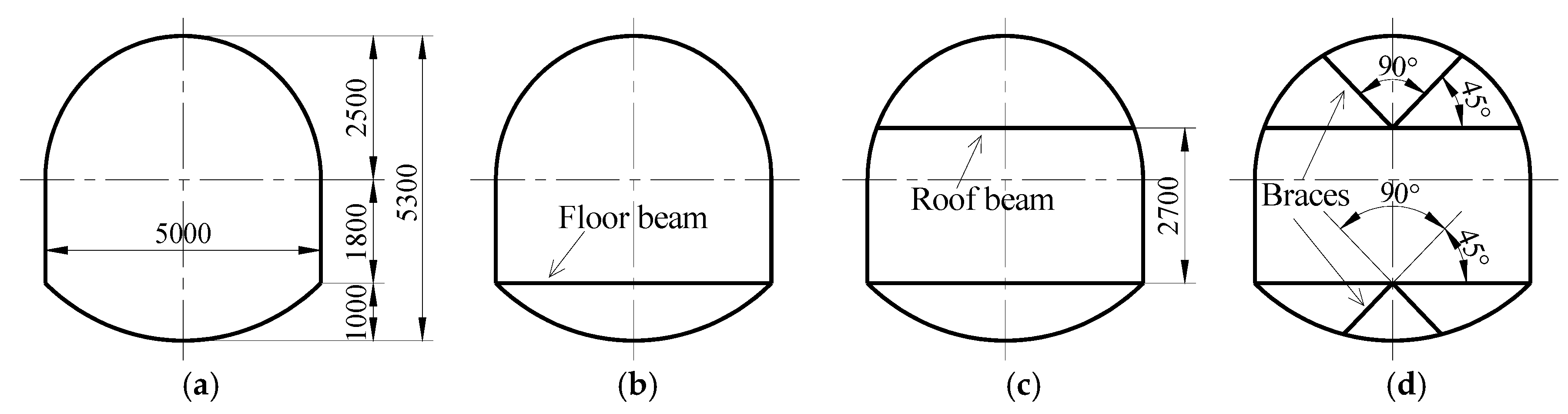
In Chagannuoer coal field, the roadway was excavated with dimensions of 5000 mm in width and 5300 mm in height (1000 mm invert), corresponded full-scale set, as presented in Figure 3a. For comparison, this steel set, without internal structures and universally used in situ, is designated as original set. Based on original set, three new sets, including a floor beam set (Figure 3b), a roof + floor beams set (Figure 3c), and a roof + floor beams + braces set (Figure 3d) are developed. When compared to original set, the floor beam set has an additional floor beam in bottom. As compared to the floor beam set, the roof + floor beams set has an additional roof beam 2700 mm above the floor beam. In the roof + floor beams + braces set, braces with 45° angle to floor or roof beam are added in both arches.
2.2. Scaled Sets Used in Experiments
Limited to size of loading frame, full-scale sets were unable to be tested. According to loading frame size, scaled sets were reduced to 0.4 times of full-scale sets (linear scale), namely the geometric ratio between full-scale sets and scaled sets was 2.5.
As 36 U-steel sets are universally used in coal mines, 36 U-steel (parameters in Table 1 [33]) was designated as the material of full-scale sets. This research is focused on the influence of internal structures on sets’ strength. Sets made of other materials would be studied in the future. Scaled sets’ material was chosen according to 36 U-steel. When loading, as material’s moment of inertia, section modulus and sectional area decide the strength of steel sets [34], these three parameters were chosen as material selection for scaled sets. Due to differences in properties, no material fitted all three parameters of moment of inertia, section modulus, and sectional area with exact ratio of 0.4 to 36 U-steel. Ultimately, the approximately material 12.6 I-steel (parameters in Table 1 [33]), with ratios of 0.53, 0.55, and 0.40 to 36 U-steel in parameters of moment of inertia, section modulus, and sectional area, was chosen as scaled sets’ material. All of the internal structures were also made of 12.6 I-steel. Uncompleted roof + floor beams + braces scaled set is shown in Figure 4.
2.3. Scaled Sets Loading State in Experiments
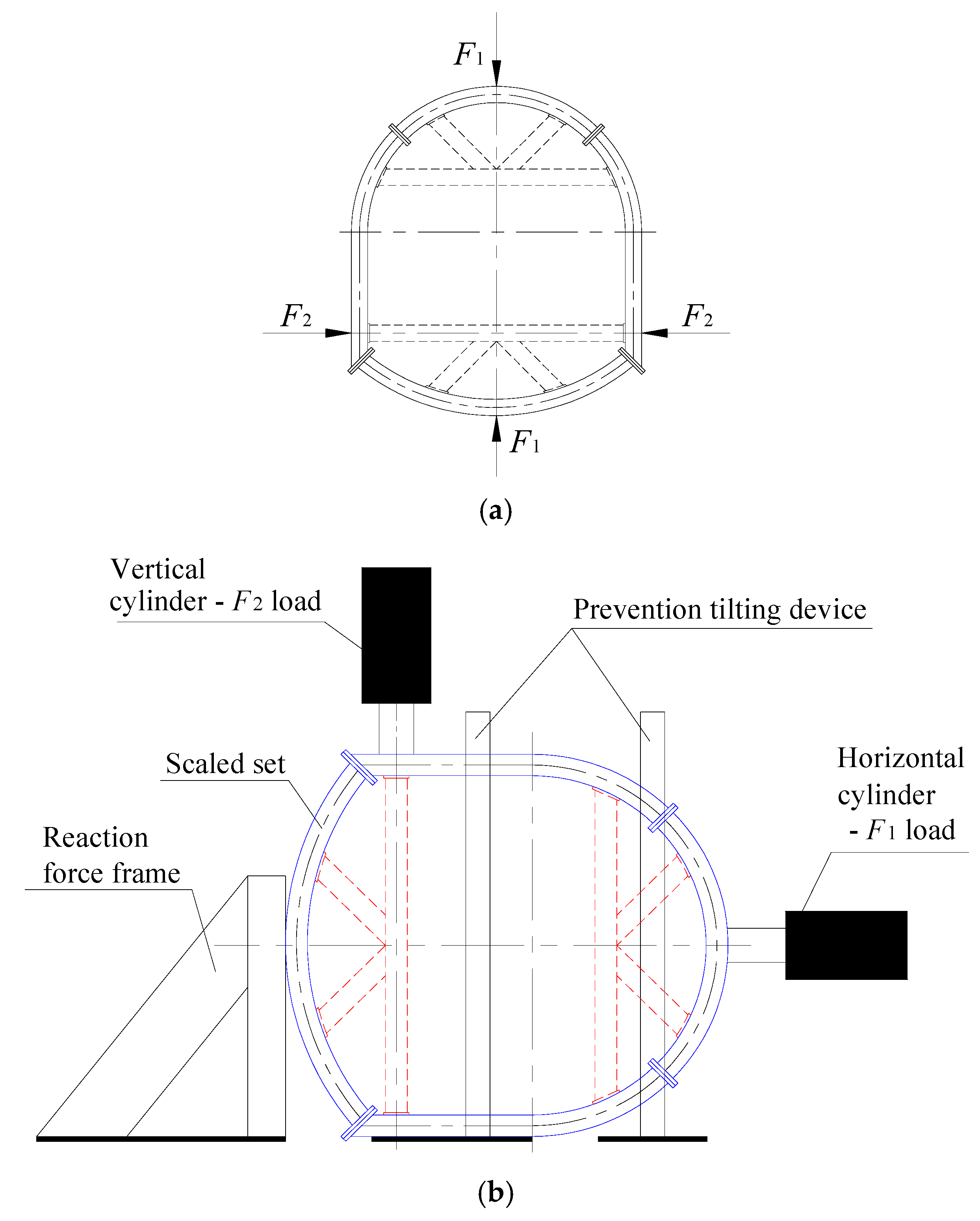
When simplifying the loading state, it is assumed that the concentrated load F1 is applied on top arch and bottom arch, while concentrated load F2 is applied on two bottom corners simultaneously (Figure 5a) in experiments. Namely, F1 and F2 are increased at the same time in loading. In loading, force control is used firstly; while top arch or bottom corners approximately yield, the force control is replaced by displacement control. As shown in Figure 5a, in force control stage, the force of F2 is chosen as 2 times the force of F1, while in displacement control stage, the displacement of F2 is chosen as 2 times the displacement of F1. Sets under complex loading states will be studied in the future.
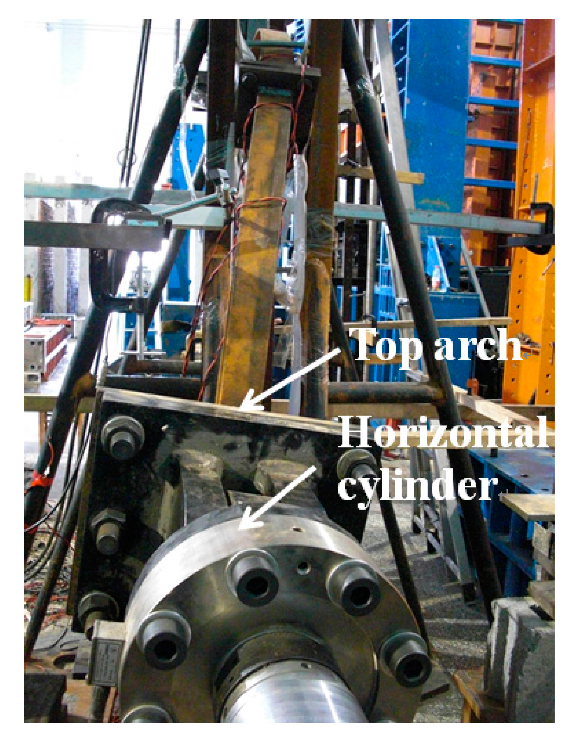
Due to the instability of top and bottom arches, scaled sets standing as in situ was almost impossible to restrain during loading. Therefore, the standing support used in situ was changed to a horizontal test configuration. In this state, the lateral wall could keep the set stable. In the horizontal direction, the top arch was loaded by horizontal hydraulic cylinder and the bottom arch was loaded by the reaction force frame. In the vertical direction, the upper side was loaded by vertical hydraulic cylinder, and the lower side was loaded by the reaction force from the ground (Figure 5b).
2.4. Deformation and Stress Monitor in Experiments
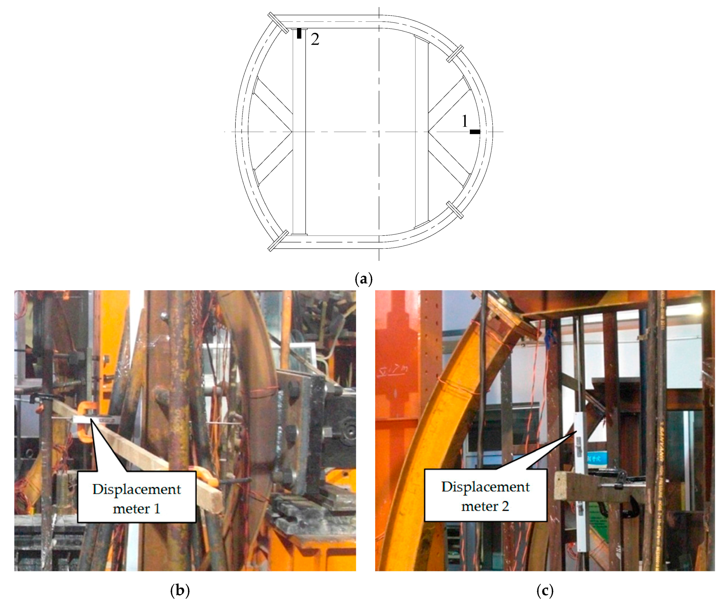
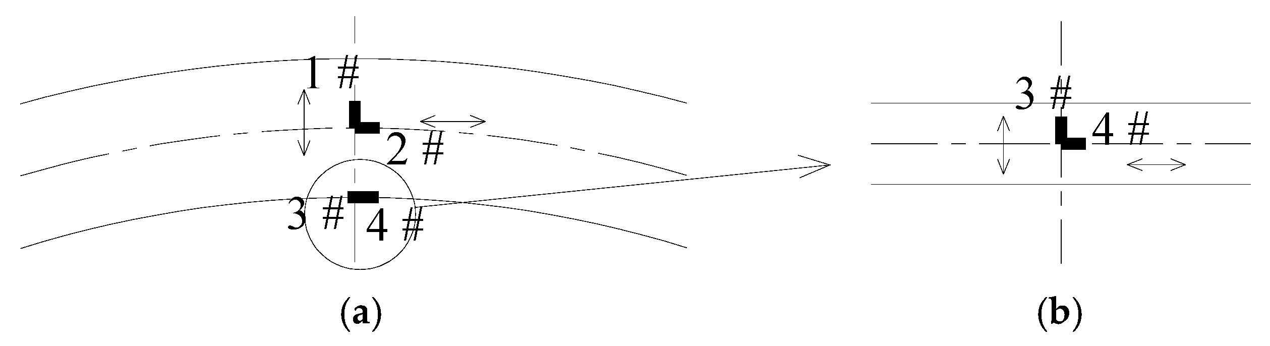
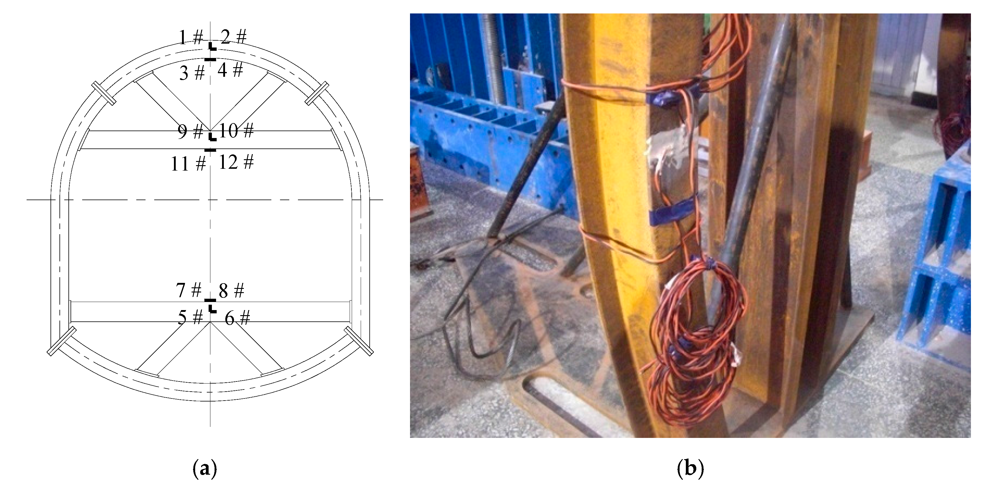
According to loading state, the scaled sets primarily deformed as horizontal deformation in top arch and vertical deformation in upper side of bottom arch. Thus, displacement meter 1 was installed to monitor horizontal displacement of top arch and meter 2 was installed to monitor vertical displacement of bottom arch upper side (Figure 6). According to loading state as well, large stress primarily occurred at top arch and floor beam. Thus, strain gauges are affixed on top arch and floor beam to monitor strain ε (and hence stress acquired by multiplied by E). BX120-3AA strain gauges, with sensitive grid 3 mm in length and 2 mm in width, as well as measurement range from −6000 to 6000 με, are used for strain monitoring in experiments. For comparison of stresses in roof beam, gauges were also affixed on roof beam to monitor strains. At each site, four gauges were used to monitor stresses along different directions. In each site, four gauges were divided into two groups and two gauges were perpendicular to each other in each group. As gauges in top arch (Figure 7), for example, the two groups (1#, 2#, and 3#, 4#) were affixed to the web (1#, 2#) and inside flange (3#, 4#), respectively. In scaled sets, the layout and number of gauges are shown in Figure 8. Gauges 1#, 5#, and 9# were used to monitor strains along horizontal direction. Gauges 2#, 4#, 6#, 8#, 10#, 12# were used to monitor strains along vertical direction. Gauges 3#, 7#, and 11# were used to monitor strains brought the model out of plane.
3. Results
For comparison, scaled sets of original set, floor beam set, roof + floor beams set, roof + floor beams + braces set are designated as models 1, 2, 3, and 4, respectively.
3.1. Displacement in Experiments
3.1.1. Horizontal Displacement in Top Arch
After loading, the top arch in model 4 is shown in Figure 9. The horizontal load F1 and its correspondence displacement Dh of top arch are shown in Figure 10. The horizontal stiffness fh is defined as the elastic slope of F1–Dh curve. Maximum bearing capacities (short as MBC) of models 1, 2, 3, and 4 are 176.8 kN, 162.5 kN, 277.0 kN, and 288.3 kN, respectively (Table 2). Horizontal stiffness of models 1, 2, 3, and 4 are 10.746 kN/mm, 9.878 kN/mm, 31.508 kN/mm, and 36.678 kN/mm, respectively (Table 2). In the four models, model 4 has the highest MBC and stiffness.
In models 1 and 2, bottom arches are different (one without floor beam and the other with floor beam), and top arches are the same (both without roof beam). When compared with model 1, at top arch, the MBC and horizontal stiffness in model 2 both are reduced by about 8.1%. The two curves in models 1 and 2 are overlapping in the initiation and before peak stages and are separated in the intermediate stage. At top arch, as less difference of MBC and horizontal stiffness in models 1 and 2, as well as first experiment and fine-tune during loading in model 1, it can be concluded that top arches without roof beam accounts for the same MBC and horizontal stiffness, and floor beam plays little role in top arch strengthening. As a consequence, in models 1 and 2, the MBC and stiffness of top arch is decided as 169.7 kN and 10.312 kN/mm (average of models 1 and 2).
In model 3, with roof beam in top arch and floor beam in bottom arch, the MBC and stiffness of top arch has been improved largely, and they are increased to 1.63 times and 3.06 times of those in models 1 and 2. Thus, roof beam plays an important part in top arch strengthening. In model 4, with roof beam + braces in top arch and floor beam + braces in bottom arch, the MBC and horizontal stiffness of top arch are increased to 1.70 times and 3.56 times of those in models 1 and 2, and to 1.04 times and 1.16 times of those in model 3. Therefore, based on roof beam, more braces have little effect on top arch strengthening.
3.1.2. Vertical Displacement in Bottom Arch
After loading, the bottom arch in model 4 is shown in Figure 11. In four models, the relationships between vertical load F2 and its correspondence displacement Dv in bottom arch are shown in Figure 12. The vertical stiffness fv is defined as the elastic slope of F2–Dv curve. The MBC of bottom arch in models 1 to 4 are 258.8 kN, 392.1 kN, 351.0 kN, and 501.9 kN, respectively (Table 3). The vertical stiffnesses are 21.831 kN/mm, 78.069 kN/mm, 76.766 kN/mm, and 80.604 kN/mm, respectively (Table 3). In the four models, model 4 has the largest MBC and stiffness.
In models 2 and 3, top arches are different (one with roof beam and the other without roof beam), and bottom arches are the same and both are reinforced by floor beam. Because of the loading frame inclined in model 2 experiment, loading was stopped at peak, and then unloaded. The MBC in model 2 is a little higher than that in model 3. When compared with model 2, the MBC of model 3 is reduced by about 10.5%. As bottom arches are both strengthened by floor beam, the vertical stiffness is approximately the same in these two models. As compared with model 2, the vertical stiffness of model 3 is reduced only about 1.7%. Consequently, it can be concluded that bottom arch reinforced by floor beam accounts for the same MBC and stiffness, and roof beam in top arch plays little role in bottom arch strengthening. Then, in the bottom arch, when reinforced by floor beam, the MBC and stiffness are increased to 371.6 kN and 77.418 kN/mm (average of models 2 and 3), respectively. In the bottom arch, the MBC and stiffness of models 2 and 3, with floor beam, are about 1.44 times and 3.55 times of those in model 1, without floor beam. So, the floor beam plays an important role in bottom arch strengthening. In model 4, with roof beam + braces in top arch and floor beam + braces in bottom arch, the MBC and vertical stiffness of bottom arch are increased to 1.94 times and 3.69 times of those in model 1, and to 1.35 times and 1.04 times of those in models 2 and 3. Therefore, based on floor beam, more braces also have some effect on bottom arch strengthening.
In models 3 and 4, with floor beam in bottom arch, there is a constant load after peak (Figure 12). This is because yielded floor beam and bottom arch combine together to afford and avoid bearing capacity loss rapidly. Due to the incline of loading frame in model 2, the post peak stage was lost. In models 3 and 4, the constant loads in post peak reaches about 386.6 kN and 415.1 kN respectively; while in model 1, the MBC of bottom arch is only about 258.8 kN. The constant loads in post peak are much higher than the MBC in model 1. Thus, steel set with floor beam in bottom arch allows releasing some deformation stress while maintaining high supporting strength, which could better meet the requirements of roadway supporting in high deformation conditions.
3.2. Stresses in Experiments
3.2.1. Stresses in Top Arch
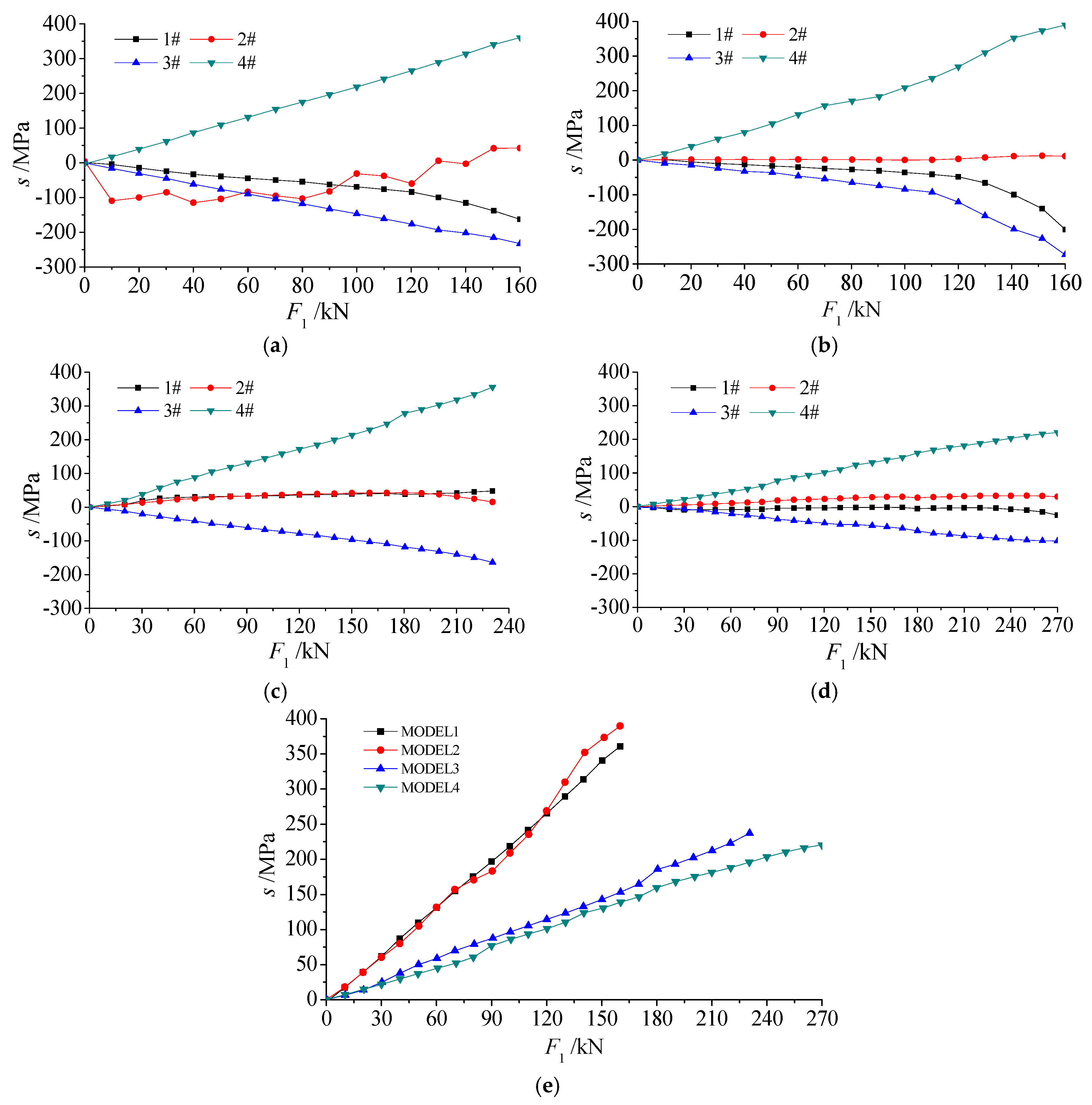
In top arch, stresses derived from strain gauges of 1 to 4 are shown in Figure 13a–d. When strain values are positive, the stresses are positive, which means that the material is in tension and vice versa, the material is in compression.
In the process of loading, stress from different positions varies differently. For example, stress values of gauge 1 in models 1 and 2, without roof beam in top arch, increase nonlinearly as load increases. But when roof beam is added, stresses of gauge 1 in models 3 and 4 vary little and are approximately zero in the process of loading. This is because when there is no roof beam, combined with Figure 10, top arch deforms largely and the web is in compression under big deformation, but when roof beam is added, top arch deforms to a small extent and this small deformation could not generate stress in web. In four models, stress values of gauge 2 vary little as load increases. In models 2, 3, and 4, the stresses of gauge 2 is approximately zero all of the time, namely the stresses do not change as load increases. Because of the first experiment and fine-tune during loading in model 1, the stress of gauge 2 fluctuates, but tends to be 0 at last.
In four models, stress values of gauge 3 increase linearly as load increases. The stress of this gauge corresponds to the out-of-plane deformation of top arch. In four stresses in each model, this stress is the larger one. Hence, in experiments, the out-of-plane deformation is one component of the main deformation and is one main cause for top arch yield. In experiments, whether or not more facilities used for top arch fixation will improve the MBC and stiffness of top arch will be studied in the future. In four models, stresses of gauge 4 increase linearly as load increases. The stress of this gauge corresponds to the bending inward deformation of top arch. In four stresses of each model, this stress is the largest one. Hence, in experiments, top arch bending inward is the major deformation and major cause for top arch yield. When bending strength of top arch is improved, the MBC of top arch will be improved further.
As the stresses of gauge 4 are the largest stress in four models, a comparison of these stresses presents in Figure 13e. In Figure 13e, stresses could be divided into two categories: stresses in models 1 and 2, and stresses in models 3 and 4. Without roof beam in top arch, the stresses are approximately the same in models 1 and 2. Even one more floor beam in model 2, top arches without roof beam in models 1 and 2 approximately account for the same stresses, thus it can be concluded that floor beam plays little role in top arch strengthening, which is in accordance to the displacement results. With roof beam in top arch, the stresses are approximately the same in models 3 and 4. Although four more braces in model 4 than in model 3, the stresses are approximately the same in these two models. Therefore, it indicates that, based on roof beam, more braces play little role in top arch strengthening, which is in accordance to displacement results as well.
When reinforced by roof beam in top arch, the stresses in models 3 and 4 are much smaller than those in models 1 and 2. The average slope of stress curves in models 3 and 4 is about 0.87, and the average slope of stress curves in models 1 and 2 is about 2.14. Under the same load, stress in models 3 and 4 is only about 40.7% of the stress in models 1 and 2. Hence, the MBC in model with roof beam is much higher than those without roof beam, which indicates that the roof beam plays a significant effect in top arch strengthening.
3.2.2. Stresses in Floor Beam
In models 2, 3, and 4, the stresses derived from gauges 5, 6, 7, and 8 are shown in Figure 14a–c. In experiments, ignoring the stresses in compression or in tension, four stresses in each model increase approximately linearly as load increases. In models, the stress from gauge 5 corresponds to deformation along horizontal direction, and the stress from gauge 7 corresponds to the deformation of out-of-plane motion. The stresses from gauges 6 and 8 correspond to the compressive deformation along vertical direction.
Stresses of gauges 5 and 7 are small and almost in equal. Therefore, under vertical loads, deformation along horizontal direction and deformation of out-of-plane motion are small. Stresses of gauges 6 and 8 are large and are approximately the same. Different gauge positions account for different distance to vertical loading axis, so little difference appears in stresses of gauges 6 and 8. Stresses from gauges 6 and 8 are much larger than stresses of gauges 5 and 7, which indicates that floor beam mainly deformed in terms of vertical compression. When the compressive strength of floor beam is improved, the bottom arch MBC will be improved further.
In floor beam, stress from gauge 8# is the largest stress in floor beam. In models 2, 3, and 4, comparisons of the largest stress are shown in Figure 14d. In models 2 and 3, with floor beam in bottom arch, stresses in these two models are approximately the same and the average slope of stress curves is about −0.68. Even one more roof beam in model 3, the stresses in models 2 and 3 are approximately the same, so it can be concluded that roof beam plays little role in floor beam (namely on bottom arch) strengthening. In model 4, there are two more braces in top arch and two more braces in bottom arch than in model 3. Roof beam plays little role in floor beam strengthening, two braces in top arch even hard to provide component force to resist vertical load, so the reinforcing effect of these two top arch braces can be neglected. But, two braces in bottom arch could provide component force to help floor beam resisting vertical load, which induced smaller stress in model 4 than in models 2 and 3. In model 4, the slope of the stress curve is reduced to −0.20. Under the same load, the stress in model 4 is only about 29.4% of stress in model 2 or model 3. Namely, the strength of bottom arch in model 4 is improved further than that in model 2 or model 3. Therefore, two bottom braces also play some role in bottom arch strengthening.
3.2.3. Stresses in Roof Beam
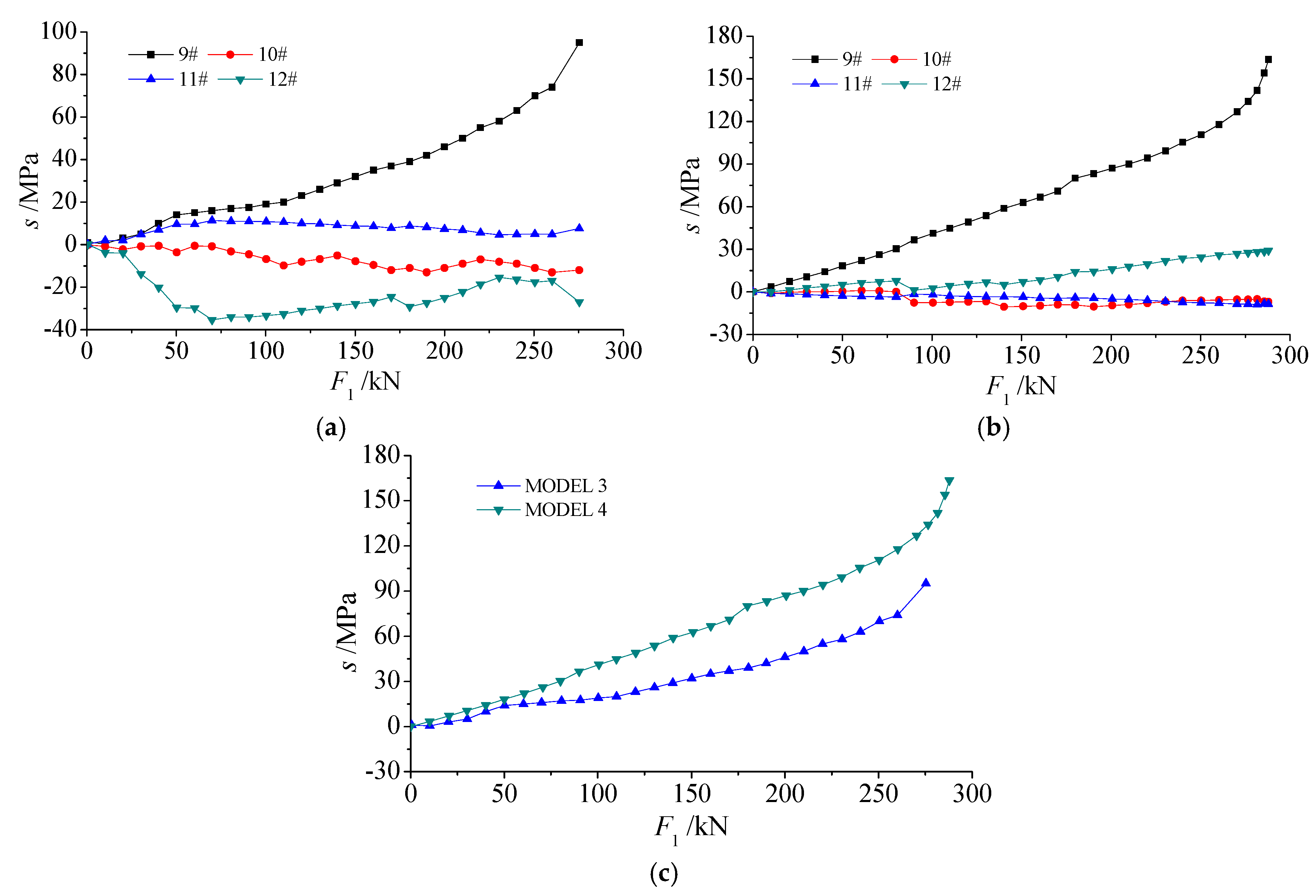
In models 3 and 4, stresses derived from gauges 9 to 12 are shown in Figure 15a,b. In roof beam, the stress of gauge 9 is the largest stress in two models, at the same time other stresses are small and could not cause roof beam to yield. The stresses from gauge 9 are compared in Figure 15c: the stress in model 3 is smaller than that in model 4, which is reinforced by braces in the top arch. In roof beam, stress from gauge 9 accounts for the deformation along horizontal direction. In model 4, the force from the horizontal actuator is transferred directly to the roof beam by the braces. When there are no braces, there is a buffering space between force application point and roof beam, which is in favor of stress releasing in top arch. When combined with deformation in top arch, based on roof beam, more braces play little role in top arch strengthening. Even worse was that two more braces could induce extra stress in roof beam and reduce the stability of top arch. So additional braces are disadvantage for top arch reinforcing.
4. Discussion
As limits of bolting, cabling, and grouted bolting in roadway supporting in swelling soft rocks, high strength steel set has become an effective approach for roadway support in this rock. In experiments, new sets reinforced by internal beams and braces exhibit a higher strength than the original set. As mentioned above, pipe sets filled with concrete has higher strength than original set, but these installation procedures, including assembling and grouting, is more complicated than the original set [17,18]. When compared with original set, the total mass of each new set has been increased, but the mass of each segment has not increased (the assembly of set is usually carried out in driving face after each segment manufactured on ground). Thus, the installation of new sets is by no means more difficult than the original set.
In this research, roof beam, floor beam, and two bottom arch braces all play important roles in sets reinforcing. In this research, effects of beams and braces with fixed positions have been tested in experiments. Whether or not sets reinforced by different positions beams and braces have higher strength needs to be studied in the future. In experiments, the horizontal loading on bottom arch was passive loading and was applied by reaction force frame, thus there was no horizontal deformation in bottom arch. If the passive loading is replaced by active loading as top arch, there would be horizontal deformation in the bottom arch. Transmitted by braces as top arch, this horizontal deformation will induce extra stress in floor beam. Whether or not this extra stress will reduce the strength of bottom arch needs to be studied in the future.
5. Conclusions
As special geological conditions in swelling soft rocks and limits of bolting, cabling, and grouted bolting in these rocks, new steel sets strengthened by internal beams and braces have been proposed in this paper. In order to assess the strengths of the new sets, four scaled sets have been manufactured and tested in loading experiments. Displacements and stresses data in key positions were obtained.
Results indicate that floor beam has little effect, but roof beam perfoms a significant effect in top arch strengthening. The MBC and stiffness of top arch with roof beam are increased to 1.63 times and 3.06 times of those in original set without roof beam. Roof beam has little effect, but floor beam plays significant role in bottom arch strengthening. The MBC and stiffness of bottom arch with floor beam are increased to 1.44 times and 3.55 times of those in original set without floor beam. Furthermore, based on roof beam, more braces has little effect on top arch strengthening, but based on floor beam, two more braces in bottom arch also has some effect on bottom arch strengthening.
Acknowledgments
This study was supported by the Program of National Key Research and Development (No. 2016YFC0600903); the Program of Introducing Talents of underground clean energy development (No. B14006); and the National Natural Science Foundation of China (No. 51604164).
Author Contributions
Renshu Yang and Qinghai Li conceived and designed the experiments; Xianlei Zhu performed the experiments; Qinghai Li and Qing Li analyzed the data; Qinghai Li wrote the paper.
Conflicts of Interest
The authors declare no conflict of interest.
References
- Butscher, C.; Huggenberger, P.; Zechner, E. Impact of tunneling on regional groundwater flow and implications for swelling of clay-sulfate rocks. Eng. Geol. 2011, 117, 198–206. [Google Scholar] [CrossRef]
- Loui, J.P.; Jhanwar, J.C.; Sheorey, P.R. Assessment of roadway support adequacy in some Indian manganese mines using theoretical in situ stress estimates. Int. J. Rock Mech. Min. Sci. 2007, 44, 148–155. [Google Scholar] [CrossRef]
- Nierobisz, A. Investigation of mine roadway support load during seismic events. J. Min. Sci. 2012, 48, 298–307. [Google Scholar] [CrossRef]
- Ulusay, R.; Aydan, Ӧ.; Geniş, M.; Hisataka, T. Stability assessment of avanos underground congress centre (Cappadocia, Turkey) in soft tuffs through an integrated scheme of rock engineering methods. Rock Mech. Rock Eng. 2013, 46, 1303–1321. [Google Scholar] [CrossRef]
- Schwingenschloegl, R.; Lehmann, C. Swelling rock behaviour in a tunnel: NATM-support vs. Q-support-A comparison. Tunnel. Undergr. Space Technol. 2009, 24, 356–362. [Google Scholar] [CrossRef]
- Shen, B.T. Coal Mine Roadway Stability in Soft Rock: A Case Study. Rock Mech. Rock Eng. 2013, 47, 2225–2238. [Google Scholar] [CrossRef]
- Szwilski, A.B. Experience with mine roadway steel arch supports in the United Kingdom. CIM Bull. 1979, 72, 92–98. [Google Scholar]
- Choquet, P. Design of steel arch supports for gate roadways. CIM Bull. 1986, 79, 88–96. [Google Scholar]
- Baxter, N.G.; Watson, T.P.; Whittaker, B.N. Study of the application of T-H support systems in coal mine gate roadways in the UK. Min. Sci. Technol. 1990, 10, 167–176. [Google Scholar] [CrossRef]
- Kang, H.P. Support technologies for deep and complex roadways in underground coal mines: A review. Int. J. Coal Sci. Technol. 2014, 1, 261–277. [Google Scholar] [CrossRef]
- Bayerl, M.; Danzebrink, B.; Thyrock, K.; Opolony, K.; Gollnick, I. Application of Hilti one step bolts for roadway support in German deep coal mines. In Proceedings of the 28th International Conference on Ground Control in Mining, Morgantown, WV, USA, 28 July 2009. [Google Scholar]
- Kang, H.P.; Lin, J.; Wu, Y.Z. Development and applications of rock bolting materials for coal mine roadways. In Proceedings of the 30th Annual International Pittsburgh Coal Conference, Beijing, China, 15–18 September 2013. [Google Scholar]
- Wu, Y.Z.; Kang, H.P.; Wu, J.X.; Fan, R.X. Development and application of mine prestressed steel bars supporting technology. Chin. J. Rock Mech. Eng. 2015, 34, 3230–3237. [Google Scholar]
- Li, S.C.; Wang, Q.; Li, W.T.; Wang, D.C.; Li, Z.; Jiang, B.; Wang, H.P.; Wang, H.T. Comparative field test study of pressure relief anchor box beam support system in deep thick top coal roadway. Chin. J. Rock Mech. Eng. 2012, 31, 656–666. [Google Scholar]
- He, M.C.; Gong, W.L.; Wang, J.; Qi, P.; Tao, Z.G.; Du, S.; Peng, Y.Y. Development of a novel energy-absorbing bolt with extraordinarily large elongation and constant resistance. Int. J. Rock Mech. Min. Sci. 2014, 67, 29–42. [Google Scholar] [CrossRef]
- Jeong, Y.Y.; Kang, H.M.; Choi, S.H.; Cho, S.H. Dynamic expansion rock bolt for rapid installing in rocks. Geosyst. Eng. 2015, 18, 85–91. [Google Scholar] [CrossRef]
- Gao, Y.F.; Wang, B.; Wang, J.; Li, B.; Xing, F.; Wang, Z.G.; Jin, T.L. Test on structural properties and application of concrete-filled steel tube support of deep mine and soft rock roadway. Chin. J. Rock Mech. Eng. 2010, 29, 2604–2609. [Google Scholar]
- Li, S.C.; Shao, X.; Jiang, B.; Wang, Q.; Wang, F.Q.; Ren, Y.X.; Wang, D.C.; Ding, G.L. Study of the mechanical characteristics and influencing factors of concrete arch confined by square steel set in deep roadways. J. China Univ. Min. Technol. 2015, 44, 400–408. [Google Scholar]
- Srivastava, L.P.; Singh, M. Effect of fully grouted passive bolts on joint shear strength parameters in a blocky mass. Rock Mech. Rock Eng. 2015, 48, 1197–1206. [Google Scholar] [CrossRef]
- Wang, L.G.; Zhang, J.; Li, H.L. A creep analysis of a bolt-grouting support structure within a soft rock roadway. J. China Univ. Min. Technol. 2009, 38, 607–612. [Google Scholar]
- Steiner, W.; Kaiser, P.K.; Spaun, G. Role of brittle fracture on swelling behaviour of weak rock tunnels: Hypothesis and qualitative evidence Sprödbruch in wenig festem Fels als Auslöser von Quellvorgängen: Beobachtungen und Analysen. Geomechanik Und Tunnelbau 2010, 3, 583–596. [Google Scholar] [CrossRef]
- Bilir, M.E. Swelling problems and triaxial swelling behavior of claystone: A case study in Tire, Turkey. Sci. Res. Essays 2011, 6, 1106–1116. [Google Scholar] [CrossRef]
- Chertkov, V.Y.; Ravina, I. Networks originating from the multiple cracking of different scales in rocks and swelling soils. Int. J. Fract. 2004, 128, 263–270. [Google Scholar] [CrossRef]
- Ghiasi, V.; Ghiasi, S.; Prasad, A. Evaluation of tunnels under squeezing rock condition. J. Eng. Des. Technol. 2012, 10, 168–179. [Google Scholar] [CrossRef]
- Schädlich, B.; Marcher, T.; Schweiger, H.F. Application of a constitutive model for swelling rock to tunneling. Geotech. Eng. 2013, 44, 47–54. [Google Scholar]
- Serafeimidis, K.; Anagnostou, G. On the time-development of sulphate hydration in anhydritic swelling rocks. Rock Mech. Rock Eng. 2013, 46, 619–634. [Google Scholar] [CrossRef]
- Mutschler, T.; Kramar, U.; Vergara, M.R.; Triantafyllidis, T. Influence of hematite coating on the activation of the swelling potential of smectite-bearing rocks. Rock Mech. Rock Eng. 2013, 46, 835–847. [Google Scholar] [CrossRef]
- Li, Q.H.; Shi, W.P.; Yang, R.S. Deformation mechanisms in a coal mine roadway in extremely swelling soft rock. SpringerPlus 2016, 5, 1–13. [Google Scholar] [CrossRef] [PubMed]
- Li, Q.H.; Shi, W.P.; Qin, Z.C. Effect of bolting on roadway support in extremely weak rock. SpringerPlus 2016, 5, 1–18. [Google Scholar] [CrossRef] [PubMed]
- Sun, X.M.; Wu, X.; He, M.C. Differentiation and grade criterion of strong swelling soft rock. Chin. J. Rock Mech. Eng. 2005, 24, 128–132. [Google Scholar]
- Aksoy, C.O.; Ogul, K.; Topal, I.; Ozer, S.C.; Ozacar, V.; Posluk, E. Numerical modeling of non-deformable support in swelling and squeezing rock. Int. J. Rock Mech. Min. Sci. 2012, 52, 61–70. [Google Scholar] [CrossRef]
- Jiao, Y.Y.; Song, L.; Wang, X.Z.; Adoko, A.C. Improvement of the U-shaped steel sets for supporting the roadways in loose thick coal seam. Int. J. Rock Mech. Min. Sci. 2013, 60, 19–25. [Google Scholar] [CrossRef]
- Jin, C.Y. Mining Design; Contemporary Chinese Audio and Video Publishing House: Beijing, China, 2004; p. 136. [Google Scholar]
- Kaiser, P.K.; Mccreath, D.R. Rock Support in Mining and Underground Construction; A.A. Balkema: Rotterdam, The Netherlands, 1992; pp. 557–567. ISBN 9054100443. [Google Scholar]
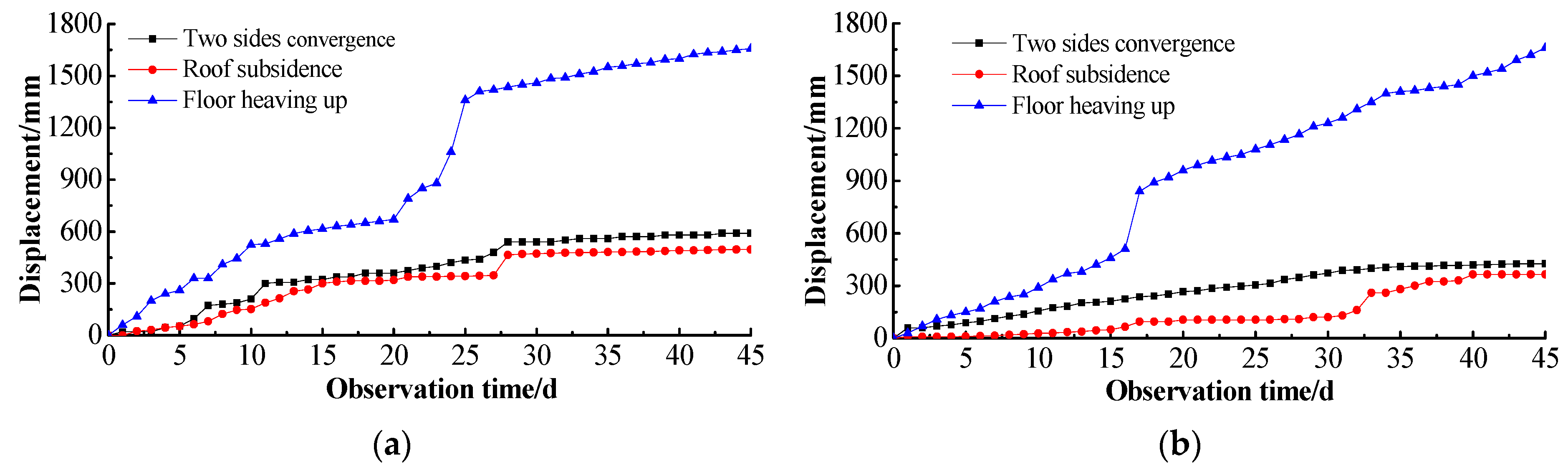
Figure 1.
Roadway deformation in stations 3 and 4 [28]. (a) Deformations of station 3; (b) Deformations of station 4.
Figure 1.
Roadway deformation in stations 3 and 4 [28]. (a) Deformations of station 3; (b) Deformations of station 4.

Figure 2.
Loads applied on steel set: (a) direct loads on steel set; (b) extra beams on steel set.
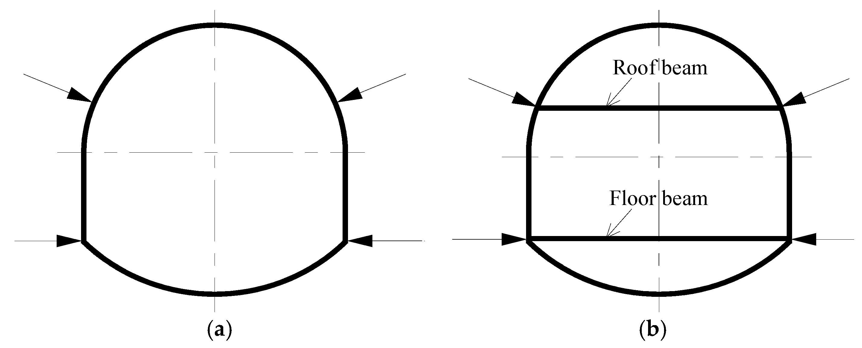
Figure 3.
Full-scale sets (units: mm): (a) original set; (b) floor beam set; (c) roof + floor beams set; and, (d) roof + floor beams + braces set.
Figure 3.
Full-scale sets (units: mm): (a) original set; (b) floor beam set; (c) roof + floor beams set; and, (d) roof + floor beams + braces set.

Figure 4.
Uncompleted roof + floor beams + braces scaled set.
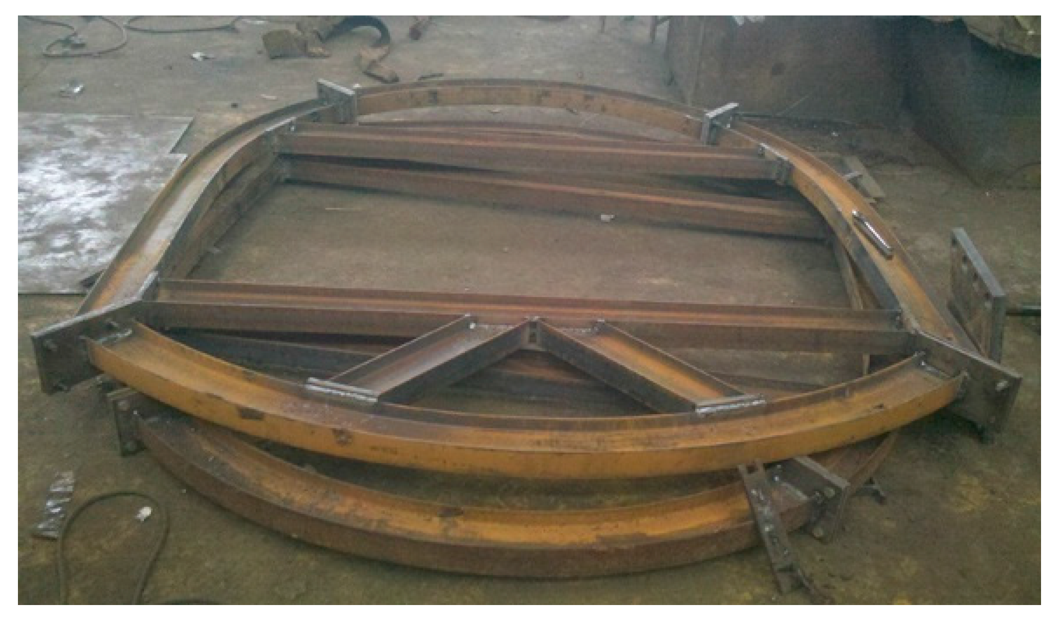
Figure 5.
Loading state on scaled sets: (a) schematic of loading state; (b) loading state in experiment.
Figure 5.
Loading state on scaled sets: (a) schematic of loading state; (b) loading state in experiment.

Figure 6.
Layout of displacement meters: (a) layout schematic of displacement meters; (b) layout of meter 1; and, (c) layout of meter 2.
Figure 6.
Layout of displacement meters: (a) layout schematic of displacement meters; (b) layout of meter 1; and, (c) layout of meter 2.

Figure 7.
Strain gauges affixed on top arch: (a) two groups in web and flange; (b) two gauges in the flange.
Figure 7.
Strain gauges affixed on top arch: (a) two groups in web and flange; (b) two gauges in the flange.

Figure 8.
Layout and numbers of strain gauges: (a) layout schematic; (b) strain gauges in scaled set.
Figure 8.
Layout and numbers of strain gauges: (a) layout schematic; (b) strain gauges in scaled set.

Figure 9.
Top arch in model 4 after loading.

Figure 10.
Relationships between horizontal load F1 and displacements Dh in top arch.
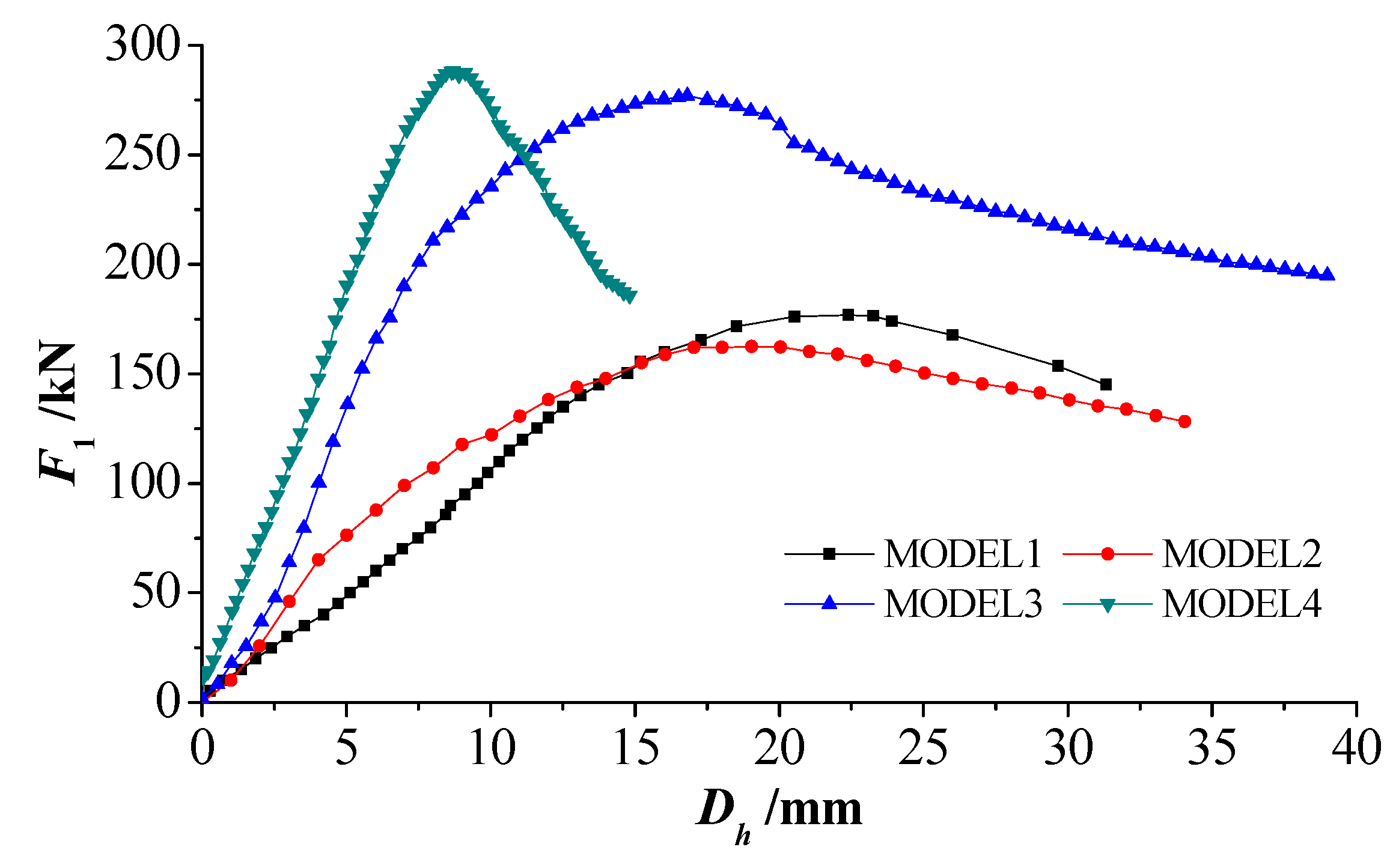
Figure 11.
Bottom arch in model 4 after loading.
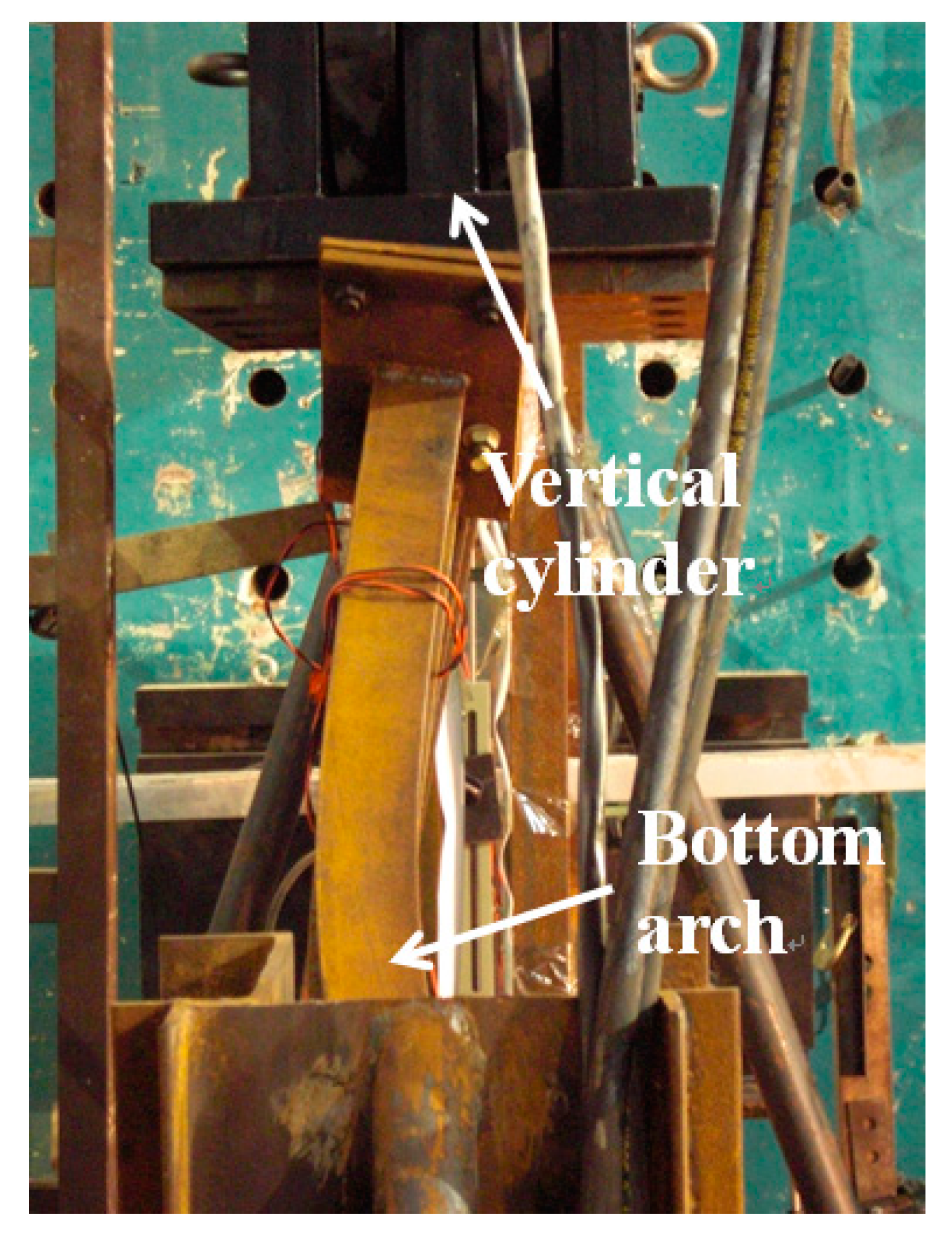
Figure 12.
Relationships between vertical load F2 and displacements Dv in bottom arch.
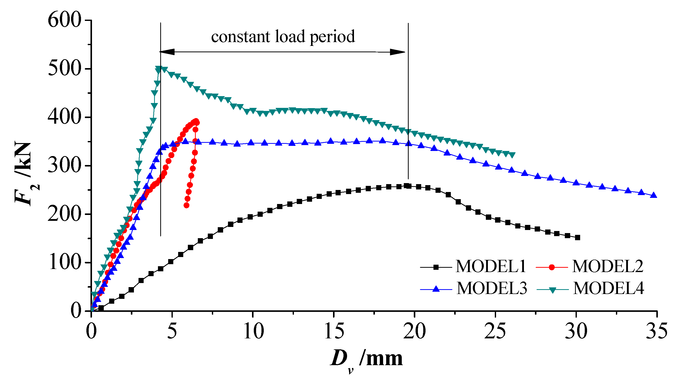
Figure 13.
Stresses in top arch: (a) stresses in model 1; (b) stresses in model 2; (c) stresses in model 3; (d) stresses in model 4; and, (e) comparison of stresses of gauge 4.
Figure 13.
Stresses in top arch: (a) stresses in model 1; (b) stresses in model 2; (c) stresses in model 3; (d) stresses in model 4; and, (e) comparison of stresses of gauge 4.

Figure 14.
Stresses in floor beam: (a) stresses in model 2; (b) stresses in model 3; (c) stresses in model 4; and, (d) comparison of stresses of gauge 8.
Figure 14.
Stresses in floor beam: (a) stresses in model 2; (b) stresses in model 3; (c) stresses in model 4; and, (d) comparison of stresses of gauge 8.
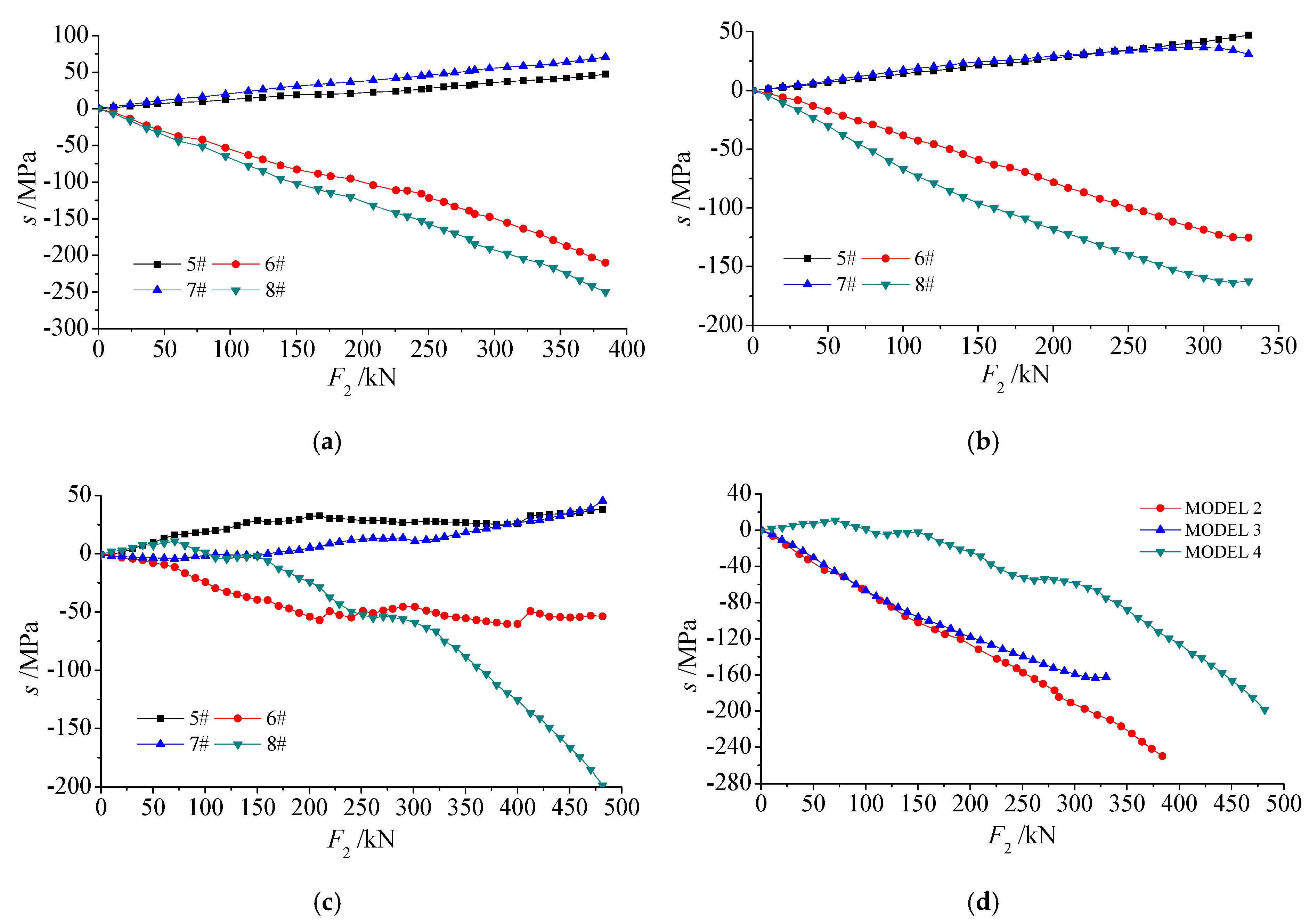
Figure 15.
Stresses in roof beam: (a) stresses in model 3; (b) stresses in model 4; and, (c) comparison of stresses of gauge 9.
Figure 15.
Stresses in roof beam: (a) stresses in model 3; (b) stresses in model 4; and, (c) comparison of stresses of gauge 9.


Table 1.
Parameters of 36 U-steel and 12.6 I-steel.
| Pattern | Theoretical Mass m (kg/m) | Sectional Area A (cm2) | Section Thickness at Neutral Axis d (cm) | Moment of Inertia I (cm4) | Elastic Modulus E (GPa) | Section Modulus W (cm3) | Static Moment S (cm3) |
|---|---|---|---|---|---|---|---|
| 36 U-steel | 35.87 | 45.69 | 1.56 | 928.65 | 200 | 141.22 | 330.05 |
| 12.6 I-steel | 14.223 | 18.118 | 0.5 | 488 | 200 | 77.5 | 44.985 |
Table 2.
Maximum bearing capacities (MBC) and horizontal stiffness in top arch.
| Results | Model 1 | Model 2 | Model 3 | Model 4 |
|---|---|---|---|---|
| MBC (kN) | 176.8 | 162.5 | 277.0 | 288.3 |
| Horizontal Stiffness fh (kN/mm) | 10.746 | 9.878 | 31.508 | 36.678 |
Table 3.
MBC and vertical stiffness in bottom arch.
| Results | Model 1 | Model 2 | Model 3 | Model 4 |
|---|---|---|---|---|
| MBC (kN) | 258.8 | 392.1 | 351.0 | 501.9 |
| Vertical Stiffness fv (kN/mm) | 21.831 | 78.069 | 76.766 | 80.604 |
© 2017 by the authors. Licensee MDPI, Basel, Switzerland. This article is an open access article distributed under the terms and conditions of the Creative Commons Attribution (CC BY) license (http://creativecommons.org/licenses/by/4.0/).
Share and Cite
MDPI and ACS Style
Yang, R.; Li, Q.; Li, Q.; Zhu, X. Assessment of Bearing Capacity and Stiffness in New Steel Sets Used for Roadway Support in Coal Mines. Energies 2017, 10, 1581. https://doi.org/10.3390/en10101581
AMA Style
Yang R, Li Q, Li Q, Zhu X. Assessment of Bearing Capacity and Stiffness in New Steel Sets Used for Roadway Support in Coal Mines. Energies. 2017; 10(10):1581. https://doi.org/10.3390/en10101581
Chicago/Turabian StyleYang, Renshu, Qinghai Li, Qing Li, and Xianlei Zhu. 2017. "Assessment of Bearing Capacity and Stiffness in New Steel Sets Used for Roadway Support in Coal Mines" Energies 10, no. 10: 1581. https://doi.org/10.3390/en10101581
Note that from the first issue of 2016, this journal uses article numbers instead of page numbers. See further details here.