Article

Integrated BMS-MMC Balancing Technique Highlighted by a Novel Space-Vector Based Approach for BEVs Application

1
Department of Electrical Eng. and IT, DIETI, University of Naples, Federico II, 80138 Napoli NA, Italy
2
Department of Electronic, Electrical and Systems Engineering, University of Birmingham, Birmingham B15 2TT, UK
*
Author to whom correspondence should be addressed.
Energies 2017, 10(10), 1628; https://doi.org/10.3390/en10101628
Submission received: 27 September 2017 / Revised: 11 October 2017 / Accepted: 12 October 2017 / Published: 17 October 2017

Abstract

:
This paper proposes a new mathematical model of modular multilevel converters for battery electric vehicles with space-vectors enabling a critical analysis of cell balancing for the battery management system. In particular, the requirements for power balancing and the actual number of degrees of freedom of the control are investigated. The paper shows that the traditional approach of cell balancing is a special case of the proposed control methodology. Numerical analyses with Matlab/Simulink™ highlight the reasons of the slow response of the standard balancing technique for specific operating conditions of the battery electric vehicle. The paper suggests potential improvements that could be introduced through the proposed generalised approach.

1. Introduction

The road transport sector is a major source of air pollutants and there is nowadays a great effort to introduce more environmentally sustainable vehicles. With a forecast of 273 million cars in 2050 in Europe and 2.5 billion worldwide [1], it is unlikely that a substantial reduction of emissions can be achieved by simply improving the technology of traditional internal combustion engines. Over the last few years, there has been a significant development of battery electric vehicles (BEVs), which are considered as a viable option to eliminate tailpipe emissions. The innovations on battery technology have constantly reduced BEVs purchase price and this has been paired up with incentive actions implemented by national and local authorities, e.g., reduced road tax, free recharge, discounts in parking lots, access to restricted traffic areas, and use of preferential lanes. However, BEVs still have a limited diffusion due to concerns over the limited range and lifetime of the battery pack. The first problem has been addressed by technological development aimed at constantly increasing the energy density of battery cells, reaching a value of 180/200 Wh/kg [2]. The second problem has been tackled by the introduction of battery management systems (BMSs) [3] that accurately manage the state of charge (SOC) of the cells [4], ensuring constant balancing for different operating conditions and limiting the effects of progressive damage and performance degradation [5], due to the uneven temperature and voltage distributions [6,7]. BMSs are traditionally electronic systems that are separated from the main traction converter.
In alternative to the traditional concept, some authors have proposed modular multilevel converters (MMCs) as at the same time they provide the functions of cell balancing and power conversion [8,9,10,11]. In the MMC topology, each submodule (SM) is formed by a battery cell and a half-bridge converter. On top of the known advantages of MMCs, i.e., high reliability, low THD, etc., this converter also allows a flexible recharge from the grid, as it can be connected to single-phase AC, three-phase AC and DC power supply without the need of intermediate filters [12,13]. However, the control algorithm is more complex as multiple tasks are required simultaneously. Indeed, the control and the minimisation of the circulating current, in transient and steady state conditions, is crucial for achieving stable and efficient operations of the MMC [14,15,16]. However, an in-depth understanding of the control variables of the converter is essential to ensure good performance in a wide range of operating conditions.
This paper addresses this knowledge gap with a new model of MMCs based on space-vectors that clearly highlights the degrees of freedom of the control. The new model explains why the SOC balancing algorithm has a different response for different operating conditions of the BEV and, hence, the standard SOC balancing technique [17,18] can be considered as a special case. In particular, the proposed model clearly highlights the critical conditions for which the traditional balancing approach becomes ineffective and the corrective actions necessary to enable cell balancing for the full frequency range. Numerical analyses in Matlab/Simulink™ on a typical city-car have been included to support the theoretical results.
The paper is structured into the following sections: Section 2 presents the system; Section 3 shows the balancing issues of the traditional approach; Section 4 shows the new space vector mathematical model of the MMC; Section 5 presents the balancing technique derived from the generalised model; Section 6 shows the numerical results; and, conclusions are reported in Section 7. The nomenclature used in this paper is reported in Table 1.

2. Description of the System

The topology of MMC considered in this paper is shown in Figure 1, together with the detail of one SM. Each SM is a half-bridge chopper, with two power switches and two antiparallel diodes; low-voltage MOSFETs can be used in order to reduce conduction and switching losses of the converter. The converter is used as a drive for a 3-phase induction motor. Each converter leg has a top and a bottom arm, whereas each arm is formed by n series-connected SMs. The top and bottom arms are connected by means of two buffer inductors, which limit the circulating current between the legs of the converter. Each SM is univocally individuated by three subscripts: the first subscript is ‘t’ or ‘b’, referring to top or bottom arm, respectively; the second subscript, ‘k’, is ‘1’, ‘2’ or ‘3’ and refers to the converter leg; the third subscript, ‘h’, indicates the cardinal number of the SM and is ‘1’, ’2’, …, ’n’.
With reference to the SM topology of Figure 1, when the switch Sa is turned ON, the SM output voltage vt,k,h is equal to the cell voltage Vcell, and, depending on the direction of the current it,k, the lithium-ion cell is charged or discharged. When the switch Sm is turned ON, vt,h,k is zero and the cell is inactive. The top (bottom) arm total voltage vt,k (vb,k) is equal to the sum of the n SMs output voltages, vt,k,h (vb,k,h). Thus, the line-to-line ac voltages have a maximum of n + 1 levels.

3. Traditional Approach to Cell Balancing

The SOC balancing technique typically has three main objectives: balancing of the cells within the same arm, balancing of the upper and lower arms of the same leg, and balancing of the three legs.
For the first objective, the cells are sorted on the basis of their SOC and if the arm’s current recharges (discharges) the cells, the modules with lowest (highest) SOC are activated. This technique assures that the SOCs of all the cells belonging to the same arm converges to the average SOCs for that arm, i.e., SOC ¯ t , k and SOC ¯ b , k .
The second and third objectives can be achieved by controlling the circulating current i c , k of each leg k, defined as:
i c , k = ( i t , k + i b , k ) / 2
Using (1), the top and bottom arm currents of the phase k can be expressed as:
i t , k = i c , k + i s , k / 2 ; i b , k = i c , k i s , k / 2
If the top and bottom arm of the same leg are controlled in a complementary way, so that n t , k + n b , k = n , where n t , k and n b , k are the number of active SMs of leg k for the top and bottom arms, the instantaneous power of these arms can be expressed as:
p t , k = v t , k i t , k = n Q max V c e l l d SOC ¯ t , k d t = ( n V c e l l 2 v s , k L d i t , k d t ) i t , k p b , k = v b , k i b , k = n Q max V c e l l d SOC ¯ b , k d t = ( n V c e l l 2 + v s , k L d i b , k d t ) i b , k
Assuming a sinusoidal load voltage and current and neglecting alternating terms, (3) can be rewritten in terms of sum and difference:
p d i f f , k = p t , k p b , k = n Q max V c e l l d ( SOC ¯ t , k SOC ¯ b , k ) d t V s , k I c , 1 , k cos θ 1 p s u m , k = p t , k + p b , k = n Q max V c e l l d ( SOC ¯ t , k + SOC ¯ b , k ) d t n V c e l l I c , d c , k V s , k I s , k cos ϕ
where I c , 1 , k is the fundamental component of the circulating current with θ 1 ; I c , d c , k is the DC component of the circulating current; V s , k is the load voltage; and, I s , k is the load current with phase ϕ .
Equation (4) shows that, while the total SOC of each leg can be controlled by the DC component of the circulating current, only the fundamental component is useful to balance the SOC between the top and bottom arms of the same leg.
The balancing problem can therefore be solved by generating proper reference values for the circulating currents i c , k * , both in terms of DC components and fundamental components for each leg k, by means of PI regulators. The DC component is controlled in a way that the quantities SOC ¯ k = SOC ¯ t , k + SOC ¯ b , k converge to the average value SOC ¯ = ( SOC ¯ 1 + SOC ¯ 2 + SOC ¯ 3 ) / 3 , whereas the fundamental component is controlled in a way that the difference SOC ¯ t , k SOC ¯ b , k is zero.
Since the contribution of each leg k to the circulating currents is dependent on the actual SOCs, the resulting 3-phase circulating currents will be composed by both a direct and an inverse sequence at fundamental frequency, with a different DC components for each phase; the zero-sequence component is identically zero due to the specific topology of the converter.

4. Generalized Mathematical Model

4.1. Main Definitions

Referring to the leg k of the MMC in Figure 1, the arms sum and difference voltages are defined as:
v σ , k = v t , k + v b , k ; v Δ , k = v t , k v b , k
while the arms sum and difference power are defined as:
{ P d c , σ , k = P d c , t , k + P d c , b , k = v t , k i t , k + v b , k i b , k P d c , Δ , k = P d c , t , k P d c , b , k = v t , k i t , k v b , k i b , k
The space vector and zero-sequence component of a generic 3-phase quantity x k are defined as:
x = 2 3 ( x 1 + x 2 e j 2 π 3 + x 3 e j 4 π 3 ) ; x 0 = 1 3 ( x 1 + x 2 + x 3 )
It is easy to verify that the space vector and zero-sequence component of the product z k = x k y k of two generic 3-phase quantities x k and y k can be obtained from the space vector and zero-sequence component of x k and y k :
z k = x k y k { z = 1 2 ( x ^ y ^ ) + y 0 x + x 0 y z 0 = 1 2 Re { x y ^ } + x 0 y 0

4.2. Voltage Balance

With reference to the MMC of Figure 1, the Kirchhoff’s Voltage Laws applied to the generic leg k yield:
{ v T , B = v t , k + v b , k + L d i t , k d t + L d i b , k d t v T , G + v B , G = v t , k v b , k + L d i t , k d t L d i b , k d t + 2 v s , k
Replacing (2) into (9), it results:
{ v T , B = v t , k + v b , k + 2 L d i c , k d t v T , G + v B , G = v t , k v b , k + L d i s , k d t + 2 v s , k
Using (5), Equation (10) become:
{ v T , B = v σ , k + 2 L d i c , k d t v T , G + v B , G = v Δ , k + L d i s , k d t + 2 v s , k
Equation (11) can be rewritten in terms of space vectors and zero-sequence components:
{ d i c d t = v σ 2 L v T , B = v σ , o v s = v Δ 2 L 2 d i s d t v T , G + v B , G = v Δ , 0 + 2 v s , 0
The first of (12) highlights that the space vector of the circulating current can be controlled by the space vector of the arms sum voltages. The second of (12) is a direct consequence of the converter topology, for which the zero-sequence component of the circulating current is identically zero. The third of (12) establishes a relation between the space vector of the arms difference voltages and the space vector of the load voltages: when considering an equivalent load, formed by the series of the load resistance and the parallel of the coupling inductors, it can be rewritten as:
v s , e q = v Δ 2
The last of (12) links the load neutral point voltage displacement to the zero-sequence component of the load voltages and of the arms difference voltage. This equation does not influence any state variable of the system, since the load neutral point is not connected, determining an additional degree of freedom, which allows to arbitrarily fix the value of v Δ , 0 .

4.3. Power Balance

Based on (2) and (5) the arms sum and difference power of the generic leg k can be expressed as:
{ P σ , k = v σ , k i c , k + 1 2 v Δ , k i s , k P Δ , k = v Δ , k i c , k + 1 2 v σ , k i s , k
which, according to (8), can also be written in term of space vectors and zero-sequence components as:
{ P σ = 1 2 v ^ σ i ^ c + v σ , 0 i c + 1 4 v ^ Δ i ^ s + 1 2 v Δ , 0 i s P σ , 0 = 1 2 Re { v σ i ^ c } + 1 4 Re { v Δ i ^ s } P Δ = 1 2 v ^ Δ i ^ c + v Δ , 0 i c + 1 4 v ^ σ i ^ s + 1 2 v σ , 0 i s P Δ , 0 = 1 2 Re { v Δ i ^ c } + 1 4 Re { v σ i ^ s }
On the other hand, by replacing the first and the third of (12) into (15) it results:
{ P σ = L i ^ c d i ^ c d t 1 4 L i ^ s d i ^ s d t + v σ , 0 i c 1 2 v ^ s i ^ s + 1 2 v Δ , 0 i s P σ , 0 = L Re { i ^ c d i c d t } 1 4 L Re { i ^ s d i s d t } 1 2 Re { v s i ^ s } P Δ = 1 2 L i ^ s d i ^ c d t 1 2 L i ^ c d i ^ s d t + 1 2 v σ , 0 i s v ^ s i ^ c + v Δ , 0 i c P Δ , 0 = 1 2 L Re { i ^ s d i c d t } 1 2 L Re { i ^ c d i s d t } Re { v s i ^ c }
The power exchanged with the coupling inductors can be calculated as:
{ P L , t , k = L i t , k d d t i t , k = L i c , k d d t i c , k + L 4 i s , k d d t i s , k + L 2 i c , k d d t i s , k + L 2 i s , k d d t i c , k P L , b , k = L i b , k d d t i b , k = L i c , k d d t i c , k + L 4 i s , k d d t i s , k L 2 i c , k d d t i s , k L 2 i s , k d d t i c , k
which in terms of sum and difference gives:
{ P L , σ , k = P L , t , k + P L , b , k = 2 L i c , k d d t i c , k + L 2 i s , k d d t i s , k P L , Δ , k = P L , t , k P L , b , k = L i c , k d d t i s , k + L i s , k d d t i c , k
resulting in the following space vectors and zero-sequence components:
{ P L , σ = L i ^ c d i ^ c d t + 1 4 L i ^ s d i ^ s d t P L , σ , 0 = L Re { i ^ c d i c d t } + 1 4 L Re { i ^ s d i s d t } P L , Δ = 1 2 L i ^ s d i ^ c d t + 1 2 L i ^ c d i ^ s d t P L , Δ , 0 = 1 2 L Re { i ^ s d i c d t } + 1 2 L Re { i ^ c d i s d t }
Finally, introducing the power transferred to the load:
P s , k = v s , k i s , k { P s = 1 2 v ^ s i ^ s P s , 0 = 1 2 Re { v s i ^ s }
and replacing (19) into (16), the power balance is calculated as:
{ P σ + P L , σ + P s = v σ , 0 i c + 1 2 v Δ , 0 i s P σ , 0 + P L , σ , 0 + P s , 0 = 0 P Δ + P L , Δ = 1 2 v σ , 0 i s v ^ s i ^ c + v Δ , 0 i c P Δ , 0 + P L , Δ , 0 = Re { v s i ^ c }

5. Balancing Technique Derived from the Generalised Model

The traditional approach to SOC balancing can be reviewed as a special case of generalised mathematical model derived in the previous section.
When the coupling inductors are correctly designed, their power can be neglected in (21). Moreover, the second of (21) simply clarifies that the total power generated by all of the cells is supplied to the load, i.e., it is not linked to the SOC balancing problem. Thus, the balancing problem can be tackled with reference to the following equations:
{ P σ v σ , 0 i c 1 2 v ^ s i ^ s + 1 2 v Δ , 0 i s P Δ 1 2 v σ , 0 i s v ^ s i ^ c + v Δ , 0 i c P Δ , 0 Re { v s i ^ c }
The space vector of the arms sum power P σ in the first equation of (22) refers to the balancing of the converter legs and must be controlled to equalise the average SOCs and obtain ( S O C σ = 0 ) . The quantities P Δ and P Δ , 0 refer instead to the balancing of the top and bottom arms. Therefore, P Δ must be controlled to ensure that on each of the three legs there is the same difference between the top arm average SOC and the bottom arm average SOC and obtain ( S O C Δ = 0 ) . The quantity P Δ , 0 must be controlled to ensure that the sum of the SOCs of the three top arms is equal to the sum of the SOCs of the three bottom arms and obtain ( SOC Δ , 0 = 0 ) . The space vector and zero-sequence component of the sum and difference arms SOC are derived by the phase components SOC σ , k = SOC ¯ t , k + SOC ¯ b , k and SOC Δ , k = SOC ¯ t , k SOC ¯ b , k .
The system of Equation (22) is composed by two vector equations and one scalar equation ( P σ , P Δ , P Δ , 0 ) , with one vector unknown and two scalar unknowns ( i c , v σ , 0 , v Δ , 0 ) , i.e., five equations for four unknowns. This implies that (22) cannot be instantaneously satisfied.
Moreover, the top and bottom arm within the same leg are typically controlled in a complementary way, resulting in v σ , 0 = n V c e l l and v Δ , 0 = 0 . This approach leaves the space vector of the circulating currents as the only manipulated variable to balance the six arms average SOCs, while the balancing of the cells SOCs within the same arm rely on the sorting technique. Therefore, in order to control the average values of the three power terms in (22), the circulating current can be composed by the following three components:
-
a DC component i c σ * that, interacting with v σ , 0 , controls P σ ;
-
an inverse component at fundamental frequency i c Δ * that, interacting with v ^ s , controls P Δ ;
-
a direct component at fundamental i c Δ , 0 * that, interacting with v s , controls P Δ , 0 ; this is indeed consistent with the traditional approach of Section 3.
Thus, the unknown variables of (22) can be calculated as:
{ i c * = i c σ * + i c Δ * + i c Δ , 0 * v σ , 0 * = n V c e l l v Δ , 0 * = 0 { i c σ * = P σ * n V c e l l i c Δ * = P ^ Δ * v s i c Δ , 0 * = P Δ , 0 * v ^ s
As previously mentioned, the Equation (23) cannot satisfy (22) instantaneously, leaving uncompensated power terms, which can be calculated in the hypothesis of steady-state operations:
{ v s = V s e j ω t = ξ n V c e l l 2 e j ω t i s = I s e j ( ω t ψ ) P s = 1 2 v ^ s i ^ s = 1 4 ξ n V c e l l I s e j ( 2 ω t ψ )
where ξ is the modulation index; V s is the load voltage amplitude; I s is the load current amplitude; ψ is the load current phase angle; ω is the electrical angular frequency.
Replacing (23) into (22) and considering (24) the residual power terms are:
{ P ˜ σ 1 4 ξ n V c e l l I s e j ( 2 ω t ψ ) 2 P ^ Δ * ξ e j ω t 2 P Δ , 0 * ξ e j ω t P ˜ Δ 1 2 n V c e l l I s e j ( ω t ψ ) ξ 2 P ^ σ * e j ω t + P Δ , 0 * e j 2 ω t P ˜ Δ , 0 Re { ξ 2 P ^ σ * e j ω t P Δ * e j 2 ω t }
The uncompensated powers contain terms oscillating at ± ω and ± 2 ω , with a magnitude dependent on the operating conditions, the balancing power reference values and the modulation index. For ω 0 the residual powers have zero average values and are not expected to have a significant influence on the SOCs, due to the slow dynamic of the electrochemical cells. On the contrary, for ω = 0 , the residual powers have a steady-state average so that (22) cannot be decoupled, i.e., the equations cannot be satisfied, not even in terms of average value, using i c as the sole control variable.
The reference power values P σ * , P ^ Δ * and P Δ , 0 * could be generated as the outputs of PI controllers processing, respectively, the errors inputs ( S O C σ * S O C σ ) , ( S O C Δ * S O C Δ ) and ( S O C Δ , 0 * S O C Δ , 0 ) , where all the SOC reference values are set to zero. On the other hand, oscillations of cells SOCs due to the residual power terms would cause a non-uniform behaviour for different operating conditions, requiring the adaptations of the regulators constants.
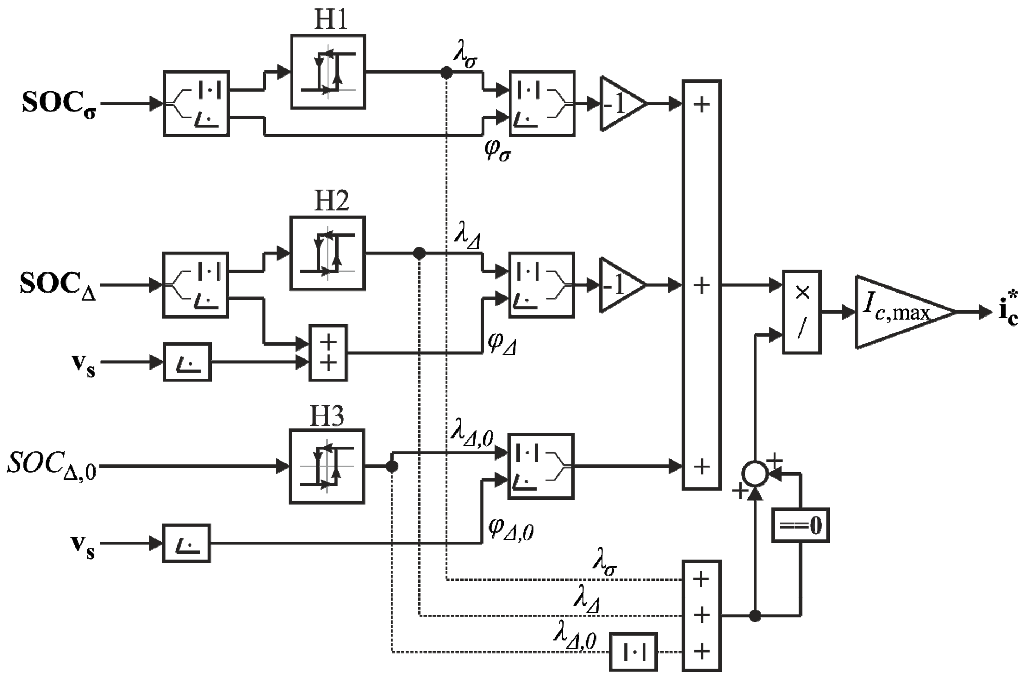
Alternatively, hysteresis controllers can be adopted in order to generate the circulating current reference value directly from the estimated SOCs. The block diagram of Figure 2 shows the calculation of the instantaneous values of the circulating current references, which, according to (22), are composed by three terms.
The first term is generated by the hysteresis controller H1: when S O C σ magnitude gets above the upper hysteresis band (UHB) the quantity λ σ becomes 1; in order to counteract the SOC deviation, the circulating current contribution is then calculated as λ σ e φ σ , where φ σ is the phase of S O C σ . When S O C σ magnitude gets below the lower hysteresis band (LHB), the quantity λ σ becomes 0. Similarly, H2 yields the second contribution via the variable λ Δ and associated phase angle φ Δ ; this angle is the difference between the phase angle of S O C Δ and that of v s because, according to (22), the circulating current counteracts the SOC deviation through the term v ^ s i ^ c .
Unlike the first two hysteresis regulators, H3 bands are symmetrical around zero and the output λ Δ , 0 can assume three values (1,0,−1): it is 1 or −1 when SOC Δ , 0 is above the UHB or below the LHB, respectively; it switches from 1 to 0 when SOC Δ , 0 reaches zero from positive values, or from −1 to 0 when SOC Δ , 0 reaches zero from negative values. The output of H3 is calculated by associating to λ Δ , 0 the phase angle, φ Δ , 0 , which is the same of that of v s .
Theoretically, the hysteresis band limits should be chosen on the basis of the achievable balancing powers, which are a function of the circulating currents that can be injected. However, there is also a dependency on the magnitude of v s . For this reason, for the sake of simplicity, the UHB limits have been set equal. To ensure numerical stability the LHB is fixed as 1/100 of the UHB for H1 and H2, while for H3 it is set as −UHB. The final reference circulating current i c * is calculated by adding the three terms and dividing it by the number of active regulators, so that the circulating current amplitude is always set at the prefixed value I c , max representing the maximum amplitude, giving the maximum available contribution for the balance of the cells SOCs.

6. Numerical Analysis

The numerical analysis of the proposed balancing technique derived from the generalised mathematical model has been carried out in Matlab/Simulink™. The main data of the simulated system are reported in Table 2.
The balancing control technique has been analysed for three different test conditions:
  • High speed: the reference speed is set for 90% of the rated speed.
  • Low speed: the reference speed is set for 10% of the rated speed.
  • Zero speed: the reference speed is set for zero.
For each condition, the initial values of the total SOC and the SOC imbalance are set for 75% and 5%, respectively.

6.1. High Speed

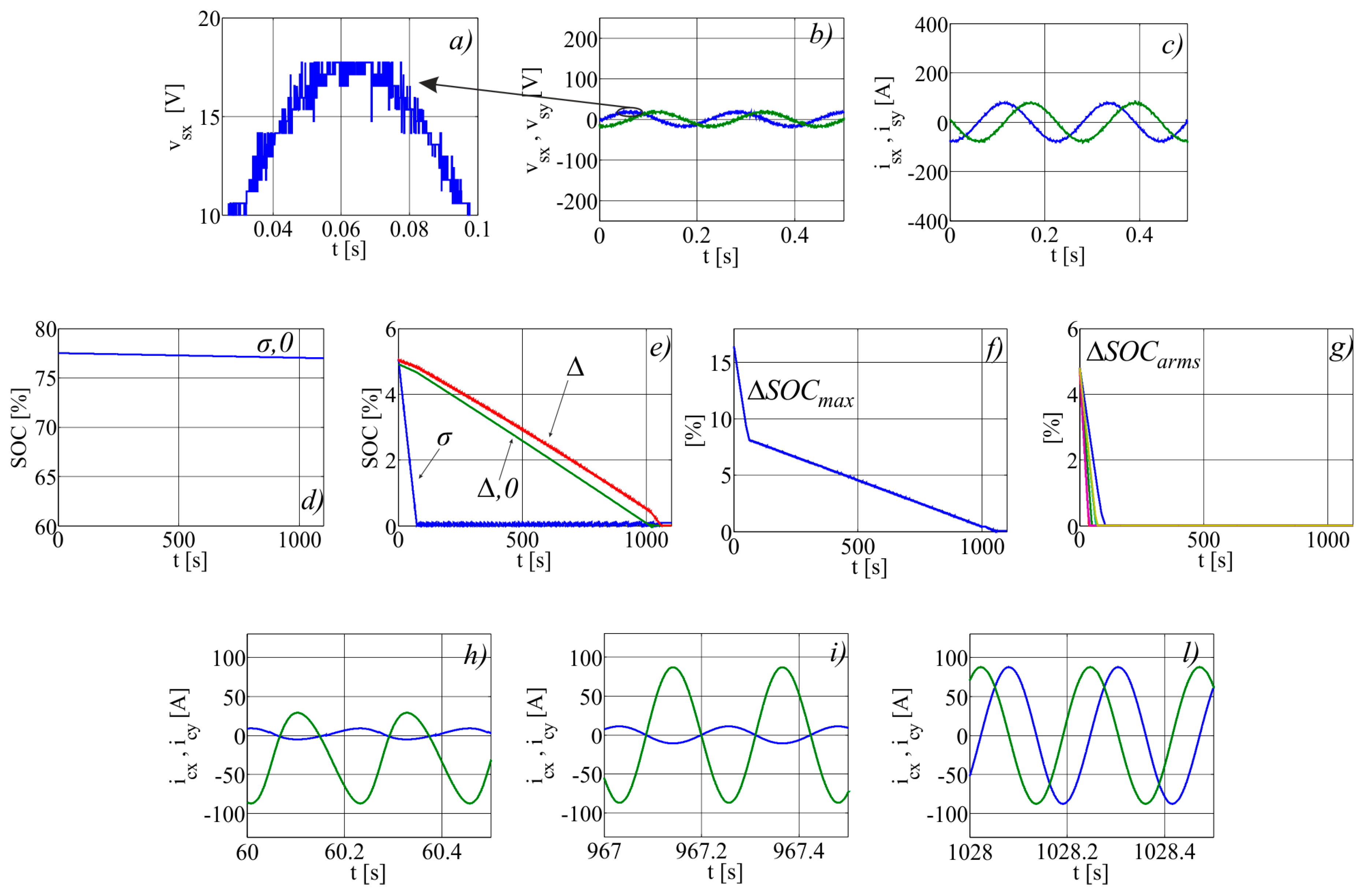
The main electrical quantities for high-speed operations are shown in Figure 3. The x and y components of the motor voltage and current space vectors are reported in Figure 3b,c respectively. Although they appear to be sinusoidal, the zoomed view of Figure 3a clarifies that the voltages are provided by a multilevel converter; the current shows instead negligible distortion.
Figure 3d shows S O C σ , 0 / 2 , corresponding to half the zero-sequence component of the arms sum SOCs and indicating the average value of all the SOCs. Given that the motor is operating at constant speed and torque, the converter output power is constant and the S O C σ , 0 component linearly decreases.
Figure 3e shows the magnitude of S O C σ , S O C Δ and SOC Δ , 0 , which are controlled by the algorithm of Figure 2. Given the initial imbalance of the cells SOCs, the three magnitudes start from the same value of 5% (all three hysteresis regulators are ON) and linearly decrease toward zero; the slopes with which the control is able to drive the SOCs depend on achievable balancing powers and the modulation index. All three SOCs components of Figure 3e are affected by the uncompensated power terms, whose magnitudes are negligible due to the slow dynamic of the electrochemical cells. As it can be noticed by Figure 3e, S O C Δ and SOC Δ , 0 show an increase of the rate of variation when S O C σ reaches zero. According to the scheme of Figure 2, indeed, when the hysteresis regulator H1 is turned OFF and λ σ switches to zero, the maximum circulating current magnitude is divided between the two remaining active regulators, increasing their contribution by a factor of 3/2; similarly, when S O C Δ reaches zero, SOC Δ , 0 undergoes a change of the rate of variation.
The circulating current waveforms are reported in Figure 3h,i,l:
(h)
all three hysteresis regulators are on: the circulating current has a DC component, a direct and an inverse component at fundamental frequency.
(i)
H1 is off, H2 and H3 are of: the circulating current has only a direct and an inverse component at fundamental frequency.
(l)
only H3 is ON: the circulating current only shows a direct component at fundamental frequency.
The difference between the maximum and the minimum SOC of all cells is depicted in Figure 3f, while Figure 3g shows the difference between the maximum and the minimum SOC of the six arms.
In about 100 s all the cells are perfectly balanced and the circulating current reference value is set to zero.

6.2. Low Speed

The main electrical quantities corresponding to low speed operations are shown in Figure 4, which is organised as Figure 3. In comparison with the high-speed operations it can be noted that the voltages are slightly distorted (a), due to their lower magnitude, but the motor currents are still sinusoidal (c). Since the motor operates at low power, the quantity S O C σ , 0 / 2 (d) decreases at slow rate as the cell discharge rate is low (d).
Figure 4e underlines the difference of the rates among the magnitudes of S O C σ , S O C Δ , and SOC Δ , 0 . When operating at low speed, the motor voltage is low and so are the 2nd and 3rd power terms in (22). The term S O C σ is instead controlled by v σ , 0 , which can be fixed independently on the motor operating conditions. As a consequence, the magnitude of S O C σ converges to zero much more rapidly than S O C Δ and SOC Δ , 0 .
The circulating current waveforms are reported in Figure 4h,i,l with reference to the cases of all the three regulators ON, two regulators ON, and only one regulator ON, respectively.
The maximum SOCs difference among the cells is reported in Figure 4f, while the maximum cells SOCs differences within the six arms are shown in Figure 4g.

6.3. Zero Speed

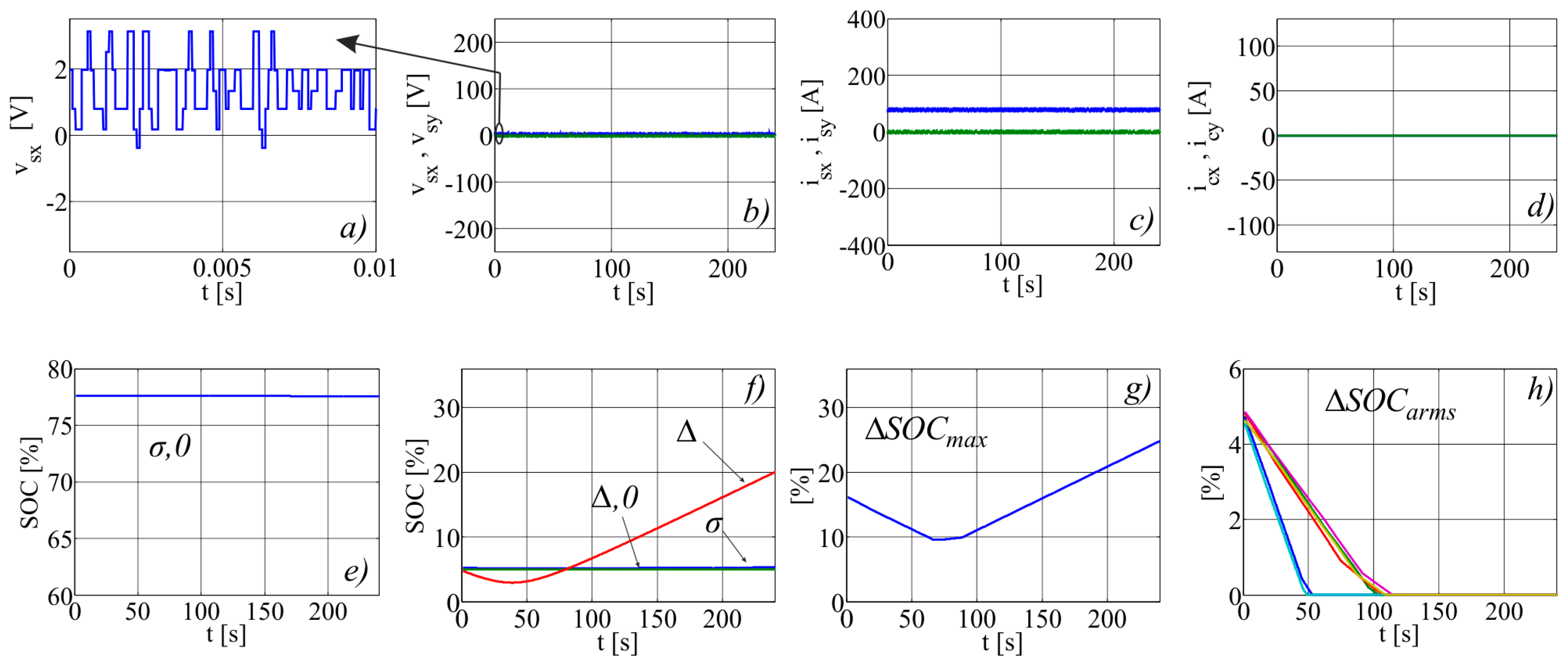
The main electrical quantities corresponding to zero speed operating condition are shown in Figure 5. At zero speed the induction motor is controlled to keep the magnetic flux at its rated value, so that a re-start can be operated at full torque without delay. Indeed, the x-axis motor current, which is shown in Figure 5c (blue line), corresponds to the rated flux current (about 25% of rated current), while the y current component (green line) is zero. The armature voltages are shown in Figure 5b with a zoomed-in view in Figure 5a, and as expected, they have low values. In this condition, the converter only provides power losses for the motor and coupling inductors, thus, the zero-sequence component S O C σ , 0 / 2 , which represents the converter average SOC, is almost constant (Figure 5e).
The magnitude of S O C σ , S O C Δ and SOC Δ , 0 is shown in Figure 5f: unlike the high and low speed operations, the three terms do not converge to zero. According to Section 5, the residual powers in (25) have an average value for ω = 0 , so that MMC arms balancing cannot be achieved using i c as the sole control variable; the x and y components of the circulating current are shown in Figure 5d. As a consequence, the difference between the minimum and maximum SOC of all cells diverges as well (Figure 5g); it is worth noting that its slope is about 0.1% s−1, determining a significant unbalance of the cells within few minutes. Since the balancing of the cells belonging to the same arm is performed by the sorting technique, even at zero speed they will eventually reach the same SOC (Figure 5h).
As long as the BEV is stationary and the induction motor is fluxed-up (e.g., traffic conditions) the average SOCs of the converter arms is divergent, eventually requiring action from the protection of electrochemical cells.
Since, for ω = 0 , (22) cannot be decoupled, the circulating current becomes a cause of unbalance: the third power term only depends on i c ( v Δ , 0 = 0 ) ; the first term mostly depends on i c ( v σ , 0 | v s | ) . As a consequence, if the circulating current reference is set to zero, the magnitude of S O C σ and SOC Δ , 0 are expected to remain almost constant.
The simulation at zero speed has been repeated with the balancing control deactivated and the results are shown in Figure 6, which is organized exactly as Figure 5. As expected, with zero circulating current (d), the magnitude of S O C σ and SOC Δ , 0 do not diverge (f). On the other hand, the motor current is still present on the second of (22), causing the unbalance of the converter SOCs through the S O C Δ term. The difference between the minimum and maximum SOC of all cells (Figure 6g) evolves in a way similar to the case of active balancing control (Figure 6g), determining a significant unbalance in short time.

7. Conclusions

This paper has presented a novel approach for the analysis of MMCs with isolated DC link based on a generalised space-vector mathematical model. The proposed model highlights the critical aspects of integrated BMSs for lithium-ion cells obtained by the standard balancing methods.
The numerical analyses carried out using the generalised model have shown that the traditional balancing technique, which uses i c as the sole control variable, does not have the same effectiveness for all of the operating conditions. In particular, it is quite effective for high-speed operations for the high magnitude of the output voltage, but it shows a slow dynamic of SOC balancing at low speeds for the low magnitude of the output voltage. Moreover, by controlling the top and bottom arms within the same leg in a complementary way to keep the DC-bus voltage constant, the traditional balancing control technique does not work at zero speed if the induction motor is kept at rated flux, regardless on the presence of the balancing control. Future work will investigate new control methods based on of a new set of control variables that will improve the limitations of the traditional approach, while retaining the same effectiveness for the whole speed range.

Acknowledgments

This work has been accomplished during the University of Naples Researcher Exchange Programme: “Programma di scambi internazionali con universitá ed istituti di ricerca stranieri per la mobilitá di breve durata di docenti, ricercatori e studiosi.

Author Contributions

Gianluca Brando, Adolfo Dannier, Ivan Spina, and Pietro Tricoli contributed equally to the work. The authors participated at the paper through a wide and balanced cooperation. They all worked at the mathematical model, the simulation set-up, the experiments and writing the manuscript.

Conflicts of Interest

The authors declare no conflict of interest.

References

  1. Statistical Office of the European Communities. Energy, Transport and Environment Indicators; Eurostat: Luxembourg, 2014; Available online: http://ec.europa.eu/eurostat (accessed on 27 September 2017).
  2. Stan, A.-I.; Swierczynski, M.; Stroe, D.-I.; Teodorescu, R.; Andreasen, S.J. Lithium ion battery chemistries from renewable energy storage to automotive and back-up power applications—An overview. In Proceedings of the 2014 International Conference on Optimization of Electrical and Electronic Equipment, OPTIM 2014, Bran, Romania, 22–24 May 2014; pp. 713–720. [Google Scholar]
  3. Yarlagadda, S.; Hartley, T.T.; Husain, I. A battery management system using an active charge equalization technique based on a dc/dc converter topology. IEEE Trans. Ind. Appl. 2013, 49, 2720–2729. [Google Scholar] [CrossRef]
  4. Gholizadeh, M.; Salmasi, F.R. Estimation of state of charge, unknown nonlinearities, and state of health of a lithium-ion battery based on a comprehensive unobservable model. IEEE Trans. Ind. Electron. 2014, 61, 1335–1344. [Google Scholar] [CrossRef]
  5. Kim, J.; Shin, J.; Chun, C.; Cho, B.H. Stable configuration of a Li-ion series battery pack based on a screening process for improved voltage/SOC balancing. IEEE Trans. Power Electron. 2012, 27, 411–424. [Google Scholar] [CrossRef]
  6. Panchal, S.; Dincer, I.; Agelin-Chaab, M.; Fowler, M.; Fraser, R. Uneven temperature and voltage distributions due to rapid discharge rates and different boundary conditions for series-connected LiFePO4 batteries. Int. Commun. Heat Mass Transf. 2017, 81, 210–217. [Google Scholar] [CrossRef]
  7. Panchal, S.; Dincer, I.; Agelin-Chaab, M.; Fraser, R.; Fowler, M. Experimental and simulated temperature variations in a LiFePO4–20Ah battery during discharge process. Appl. Energy 2016, 180, 504–515. [Google Scholar] [CrossRef]
  8. Deng, F.; Chen, Z. Voltage-Balancing Method for Modular Multilevel Converters Switched at Grid Frequency. IEEE Trans. Ind. Electron. 2015, 62, 2835–2847. [Google Scholar] [CrossRef]
  9. D’Arco, S.; Piegari, L.; Tricoli, P. Power and balancing control considerations on modular multilevel converters for battery electric vehicles. In Proceedings of the 2013 15th European Conference on Power Electronics and Applications (EPE), Lille, France, 2–6 September 2013; pp. 1–9. [Google Scholar]
  10. D’Arco, S.; Piegari, L.; Quraan, M.S.; Tricoli, P. Battery charging for electric vehicles with modular multilevel traction drives. In Proceedings of the 7th IET International Conference on Power Electronics, Machines and Drives (PEMD 2014), Manchester, UK, 8–10 April 2014; pp. 1–6. [Google Scholar]
  11. Maharjan, L.; Inoue, S.; Akagi, H.; Asakura, J. State-of-Charge (SOC)-balancing Control of a battery energy storage system based on a Cascade PWM Converter. IEEE Trans. Power Electron. 2009, 24, 1628–1636. [Google Scholar] [CrossRef]
  12. D’Arco, S.; Piegari, L.; Tricoli, P. A modular converter with embedded battery cell balancing for electric vehicles. In Proceedings of the Electrical Systems for Aircraft, Railway and Ship Propulsion (ESARS), Bologna, Italy, 16–18 October 2012; pp. 1–6. [Google Scholar]
  13. Xu, C.; Dai, K.; Chen, X.; Kang, Y. Unbalanced PCC voltage regulation with positive- and negative-sequence compensation tactics for MMC-DSTATCOM. IET Power Electron. 2016, 9, 2846–2858. [Google Scholar] [CrossRef]
  14. Ben-Brahim, L.; Gastli, A.; Trabelsi, M.; Ghazi, K.A.; Houchati, M.; Abu-Rub, H. Modular Multilevel Converter Circulating Current Reduction Using Model Predictive Control. IEEE Trans. Ind. Electron. 2016, 63, 3857–3866. [Google Scholar] [CrossRef]
  15. Saad, H.; Guillaud, X.; Mahseredjian, J.; Dennetière, S.; Nguefeu, S. MMC Capacitor Voltage Decoupling and Balancing Controls. IEEE Trans. Power Deliv. 2015, 30, 704–712. [Google Scholar] [CrossRef]
  16. Moon, J.-W.; Kim, C.-S.; Park, J.-W.; Kang, D.-W.; Kim, J.-M. Circulating current control in MMC under the unbalanced voltage. IEEE Trans. Power Deliv. 2013, 28, 1952–1959. [Google Scholar] [CrossRef]
  17. Quraan, M.; Yeo, T.; Tricoli, P. Design and Control of Modular Multilevel Converters for Battery Electric Vehicles. IEEE Trans. Power Electron. 2016, 31, 507–517. [Google Scholar] [CrossRef]
  18. Quraan, M.; Tricoli, P.; D’Arco, S.; Piegari, L. Efficiency Assessment of Modular Multilevel Converters for Battery Electric Vehicles. IEEE Trans. Power Electron. 2017, 32, 2041–2051. [Google Scholar] [CrossRef]
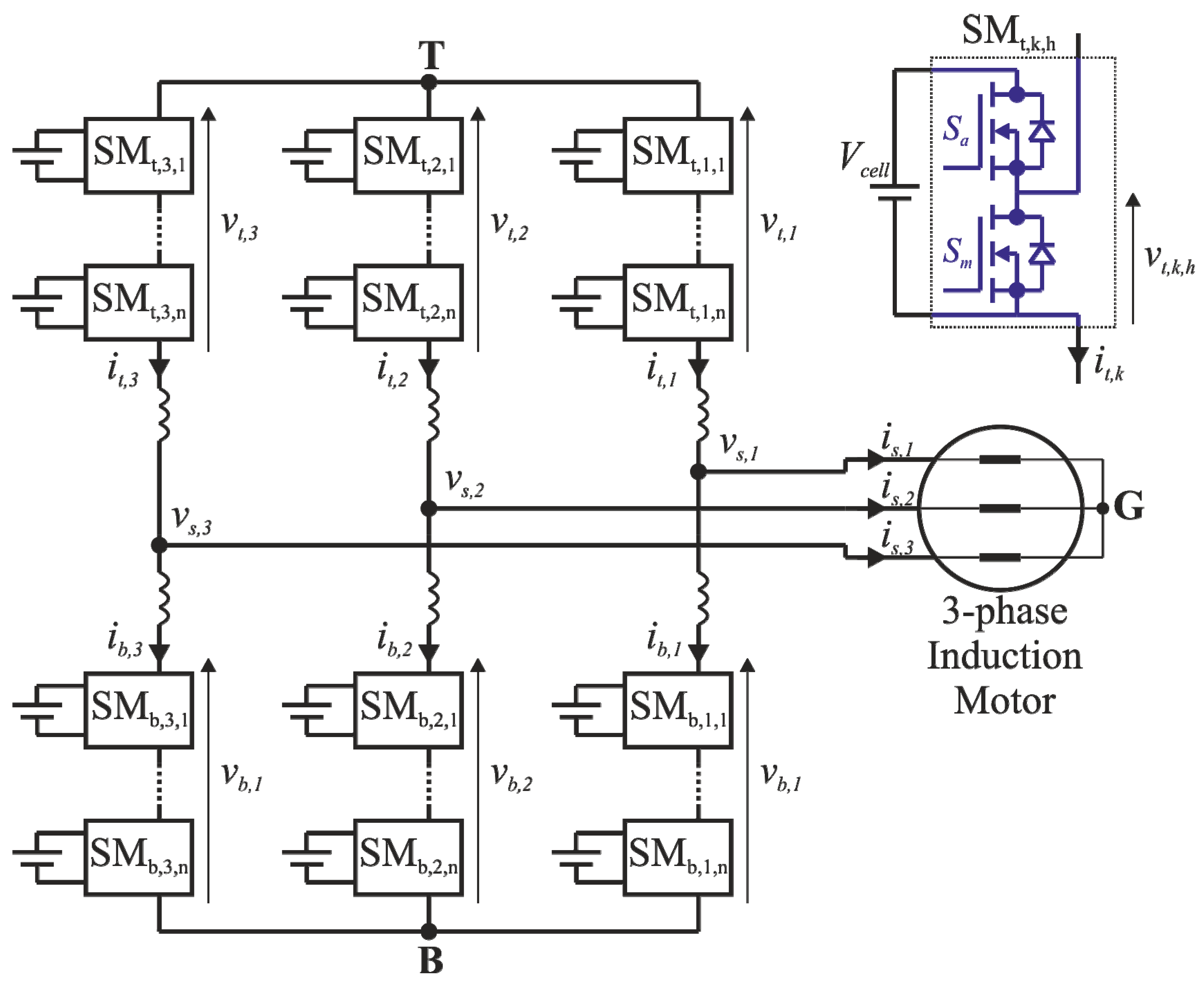
Figure 1. Modular multilevel converters (MMC) power topology.
Energies 10 01628 g001
Figure 2. Circulating current reference calculation via SOC hysteresis regulators.
Energies 10 01628 g002
Figure 3. Numerical results for high speed: (a) zoom of x motor voltage component; (b) x,y motor voltage components; (c) x,y motor current components; (d) half of the zero-sequence component of the arms sum SOCs; (e) unbalance state of charge (SOC) terms; (f) difference between the maximum and the minimum SOC of all the cells; (g) difference between the maximum and the minimum SOC of the six arms; x,y circulating current components when all three hysteresis regulators are ON (h), only two regulators are ON (i); and, only one regulator is ON (l).
Energies 10 01628 g003
Figure 4. Numerical results for low speed: (a) zoom of x motor voltage component; (b) x,y motor voltage components; (c) x,y motor current components; (d) half of the zero-sequence component of the arms sum SOCs; (e) unbalance SOC terms; (f) difference between the maximum and the minimum SOC of all cells; (g) difference between the maximum and the minimum SOC of the six arms; x,y circulating current components when all three hysteresis regulators are ON (h), only two regulators are ON (i); and, only one regulator is ON (l).
Energies 10 01628 g004
Figure 5. Numerical results for zero speed: (a) zoom of x motor voltage component; (b) x,y motor voltage components; (c) x,y motor current components; (d) x,y circulating current components; (e) half of the zero-sequence component of the arms sum SOCs; (f) unbalance SOC terms; (g) difference between the maximum and the minimum SOC of all cells; and, (h) difference between the maximum and the minimum SOC of the six arms.
Energies 10 01628 g005
Figure 6. Numerical results for zero speed deactivating the balancing control: (a) zoom of x motor voltage component; (b) x,y motor voltage components; (c) x,y motor current components; (d) x,y circulating current components; (e) half of the zero-sequence component of the arms sum SOCs; (f) unbalance SOC terms; (g) difference between the maximum and the minimum SOC of all cells; and, (h) difference between the maximum and the minimum SOC of the six arms.
Energies 10 01628 g006
Table 1. Nomenclature.
SubscriptDescription
h Arm module
k Converter leg
s Converter output electrical quantities
t , b Top arms, bottom arms
Δ Top-bottom difference
σ Top+bottom addition
0 Zero-sequence component
SymbolDescription
f Frequency
i c Circulating current
I c , max Maximum circulating current reference value
L Buffer inductance
n Number of arm sub-modules
P ˜   or   P ˜ Not compensated power term
Q max Rated capacity of the cells
SOC State of charge
v , i , p Voltage, Current, Power
V c e l l Cells voltage
V s , I s Load voltage and current amplitude
x , x ^ Generic space vector and its conjugate
λ Hysteresis regulator output
ξ Modulation Index
ψ Load current phase delay
ω Angular frequency
Table 2. Main Data of the Simulated System.
SymbolQuantityValue
-Rated motor power80 kW
-Rated motor speed2975 rpm
-Rated motor frequency50 Hz
-Rated motor voltage230 V
nNumber of cells per arm108
VcellCell voltage3.2–4.2 V
-Cell energy38 Wh
-Sampling frequency10 kHz
LRecirculating inductance50 µH