A Novel Topology of Hybrid HVDC Circuit Breaker for VSC-HVDC Application


1
Department of Electrical Engineering, Incheon National University, 119 Academy-ro, Yeonsu-gu, Incheon 22012, Korea
2
Research Institute for Northeast Asian Super Grid, Incheon National University, 119 Academy-ro, Yeonsu-gu, Incheon 22012, Korea
3
Transmission & Distribution Lab., The R&D Center of Korea Electric Power Co., 105 Munji-ro, Yuseong-gu, Daejeon 34056, Korea
*
Author to whom correspondence should be addressed.
Energies 2017, 10(10), 1675; https://doi.org/10.3390/en10101675
Submission received: 19 September 2017
/
Revised: 17 October 2017
/
Accepted: 19 October 2017
/
Published: 23 October 2017
(This article belongs to the Special Issue Emerging Power Electronics Technologies for Power Systems and Machine Drives)
Abstract
:The use of high voltage direct current (HVDC) circuit breakers (CBs) with the capabilities of bidirectional fault interruption, reclosing, and rebreaking can improve the reliable and safe operation of HVDC grids. Although several topologies of CBs have been proposed to perform these capabilities, the limitation of these topologies is either high on-state losses or long time interruption in the case bidirectional fault current interruption. Long time interruption results in the large magnitude of the fault current in the voltage source converter based HVDC (VSC-HVDC) system due to the high rate of rise of fault current. This paper proposes a new topology of hybrid CB (HCB) with lower conduction loss and lower interruption time to solve the problems. The proposed topology is based on the inverse current injection method, which uses the capacitor to enforce the fault current to zero. In the case of the bidirectional fault current interruption, the capacitor does not change its polarity after identifying the direction of fault current, which can reduce the interruption time accordingly. A switching control algorithm for the proposed topology is presented in detail. Different operation modes of proposed HCB, such as normal current mode, breaking fault current mode, discharging, and reversing capacitor voltage modes after clearing the fault, are considered in the proposed algorithm. The proposed topology with the switching control algorithm is tested in a simulation-based system. Different simulation scenarios such as temporary and permanent faults are carried out to verify the performance of the proposed topology. The simulation is performed in the Matlab/Simulink environment.
1. Introduction
The reliable and safe operation of the high voltage direct current (HVDC) grid can be improved with the use of the DC circuit breakers (CBs) [1,2,3,4,5]. The requirements for the design of CBs can be different according to the type of HVDC technologies [6]. Typically, there are two types of HVDC, traditional line-commutated current source converter (LCC-HVDC) and voltage source converter (VSC-HVDC) [7]. In the case of LCC-HVDC, the rate of rise and magnitude of the fault current is not high due to the use of the DC side reactor [8]. As a result, the time interruption of the fault current could be up to few hundred milliseconds [9]. The main focus for the design of CB in the LCC-HVDC was on the mechanism of zero current crossing. However, in the VSC-HVDC technology, the fault current increases rapidly due to the capacitive behavior of the HVDC cable and low DC side impedance [10]. Thus, the CBs for the VSC-HVDC application should have short interruption time. In addition, the CB should have capabilities of bidirectional fault current interruption, reclosing, and rebreaking to improve the reliability and safe operation of the HVDC grids [11,12,13]. The reclosing operation especially is required to avoid power outages for a long time. The rebreaking operation should be carried out for permanent faults.
Several CB topologies have been introduced in the literature. The CBs can be categorized in three types such as mechanical circuit breakers (MCBs), solid-state circuit breakers (SSCBs), and hybrid circuit breakers (HCBs) [14,15]. The design of MCBs is based on the oscillating current superimposed on the DC current to generate a current zero crossing. Thus, the characteristic of the MCBs is long interruption time (30–50 ms). Although recent developments have reduced the interruption time [16], it may be not suitable for the VSC-HVDC system. The SSCBs, which were proposed for the VSC-HVDC grid, can interrupt fault currents much faster than the MCBs [17,18,19,20]. However, these topologies have high on-state losses as well as high implementation cost compared to the MCBs [14,15]. The combination of SSCB and MCB results in HCB configurations. The HCB topology, which was introduced firstly by ASEA Brown Boveri (ABB) Group [21], can offer the advantages of both kinds of CBs. It contains a main semiconductor-based breaker (MB) using insulated-gate bipolar transistor (IGBT) and a bypass formed by semiconductor-based load communication switch (LCS) in series with an ultra-fast disconnector (UFD). This topology was based on inverse voltage generation method that reduces the fault current to zero by generating the arc voltage higher than the source voltage. This topology has lower on-state losses compared to SSCBs and short interruption time (few milliseconds). However, reclosing and rebreaking operation modes of HCB did not mentioned in this paper. The detailed analysis for the HCB with different operation modes should be considered, as mentioned in [15]. Therefore, the coordinated control of the four subunits (two semiconductor values and two mechanical switches) is analyzed in [22]. The model accurately represented the opening and closing sequences of the subunits of the HCB. In the case of the multi-terminal VSC-HVDC (MTDC) system where the fault location is difficult to recognize, the fault current might increase significantly due to the long time of fault detection, which can damage the IGBT in the auxiliary branch in this topology. Thus, this topology requires large number of semiconductor switches in the MB branch to tolerate the system voltage as well as the fault current, which results in the high implementation cost and relatively high on-state loss [23]. Reduction in the realization cost of HCBs has been researched in recent years. A HCB topology based on series-connected multiple thyristors is introduced by [24] to reduce the on-state loss. This topology is based on inverse current injection method, which generates a current zero crossing by injecting the current stored in the pre-charged capacitor on the DC fault current. However, the on-state losses in this topology is still high due to the use of IGBT in the main branch. In addition, the process of transferring fault current from the main branch to the auxiliary branch might increase the fault interruption time. Moreover, the use of external source to pre-charge capacitor might increase to overall cost of this topology. Although this topology provides the bidirectional fault current interruption, the reclosing and rebreaking capabilities of HCB have not been presented. In [25], a topology of HCB with the reclosing, rebreaking, and bidirectional fault current interruption capabilities has been proposed. The reclosing and rebreaking operations were proposed to avoid the interruption of power to the connected AC grids. An auxiliary power supply is used in this topology to charge the capacitor. In the case of bidirectional fault current interruption, the polarity of the pre-charged capacitor is changed after identifying the direction of fault current. Therefore, it takes a delay time (about 2 ms) to begin the process of the fault interruption, which results in the increase of the fault current magnitude. As a result, the topology proposed in [25] is not suitable for the VSC-HVDC system due to the high rate of rise fault current.
Since the use of the VSC-HVDC technology is a superior alternative to the LCC-HVDC due to the independent control of active and reactive power, the suitable HCB for VSC-HVDC with the capabilities of the bidirectional fault current interruption, reclosing, and rebreaking should be considered. This paper proposes a new topology of HCB to solve the above-mentioned problems. The main contributions of this paper are as follows:
- A topology of HCB based on the thyristor technique is proposed to reduce the realization cost and on-state loss. The bidirectional HCB is designed to interrupt the fault current in both directions by using silicon-controlled rectifier (SCR) devices. The polarity of pre-charged capacitor in the proposed topology is independent on the direction of the fault, which results in the reduction of the interruption time in the case of bidirectional fault current interruption. As a result, it can be used in the VSC-HVDC grid due to lower fault current interruption time. Besides, the proposed topology is capable of the reclosing and rebreaking operations without an auxiliary power supply, which results in the cost reduction.
- A switching control algorithm for the proposed HCB model to operate in different modes, such as normal, breaking, discharging, and reversing modes, is proposed. The algorithm represents sufficiently detailed protection sequence among the operation modes. The closing and opening operations of thyristors and switches detect and control accurately in case of normal and fault conditions.
The paper is organized as follows: Section 2 describes the proposed topology of HCB based on the inverse current injection method. The operation principles and design parameters of the proposed topology are explained in this section. In Section 3, a switching control algorithm for the proposed topology is presented. Simulation results are discussed in Section 4. Finally, the main conclusions are summarized in Section 5.
2. Proposed HCB and Operation Principle
2.1. Configuration of Proposed Topology
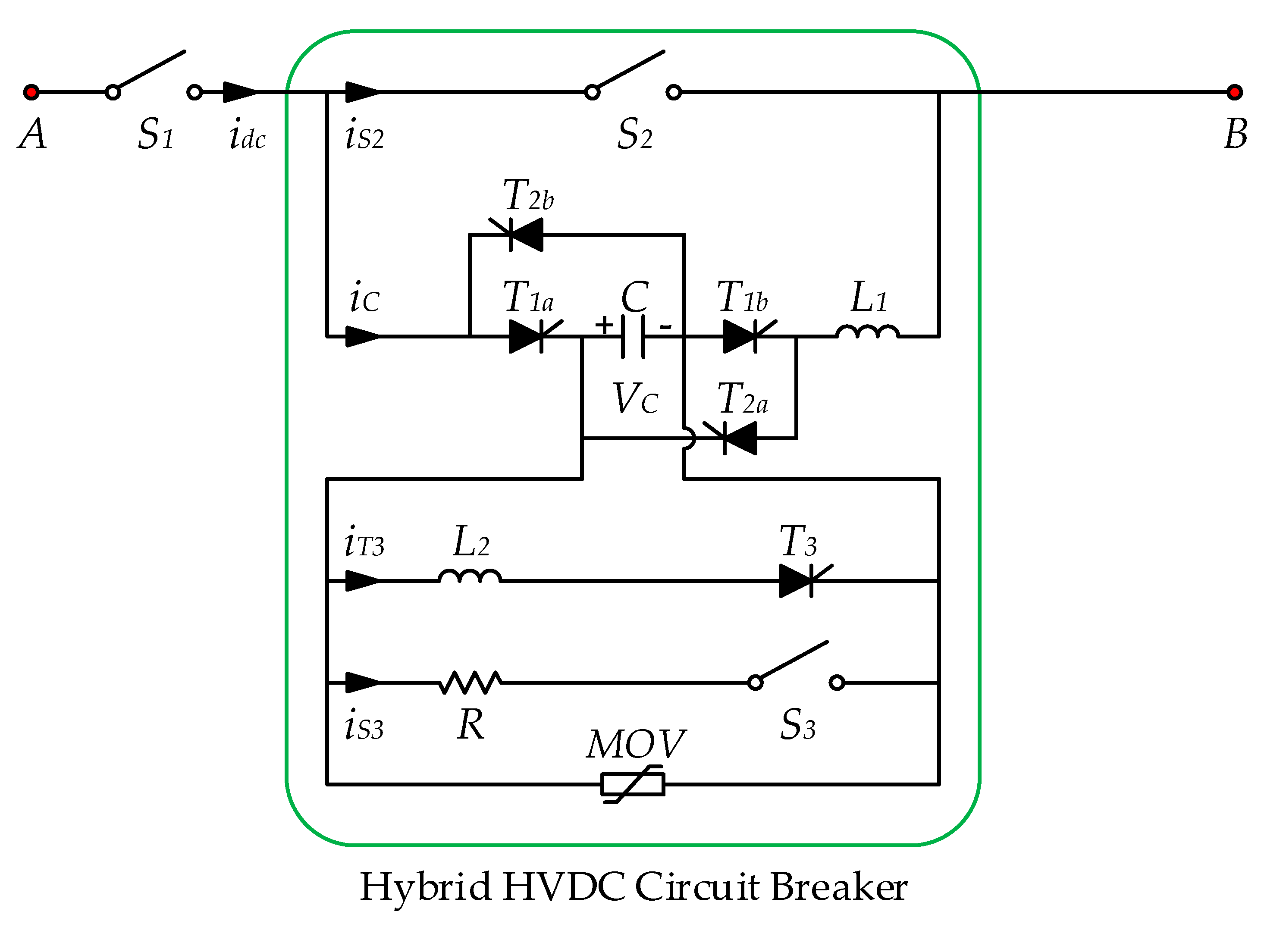
The structure of the proposed HCB with bidirectional current interruption is shown in Figure 1, which is composed of a main branch, an energy absorbing branch, and auxiliary branches. The main branch has a fast mechanical switch S2. The auxiliary branches include a capacitor C, a resistor R, a fast mechanical switch S3, two inductors (L1 and L2), and five thyristors (T1a, T1b, T2a, T2b, and T3). The T1a, T1b, T2a, and T2b are used for breaking the bidirectional fault current, whereas the T3 is employed to reverse the polarity of capacitor voltage. The absorbing branch is composed of series-parallel metal oxide varistors MOVs to protect the overvoltage of the capacitor. In addition, a residual DC current disconnector S1 is used to completely isolate the DC circuit. The mechanical switches S1, S2, and S3 consist of the vacuum interrupter to extinguish the electrical arc.
2.2. Operation Principle
The operation modes of the proposed HCB are based on predefined the states of the switches in the proposed HCB. The switches can be turned-on or turned-off depending on the operation modes. The operation of proposed HCB can be divided into four modes such as normal mode, breaking mode, discharging mode, and reversing mode. The states of the switches are different according to the direction of the current, as shown in Table 1. The direction of the fault current is positive when it flows from A-side to B-side and negative for the flow from B-side to A-side. The delay time for operating switches in the proposed HCB is neglected for the case of interpretation in the description.
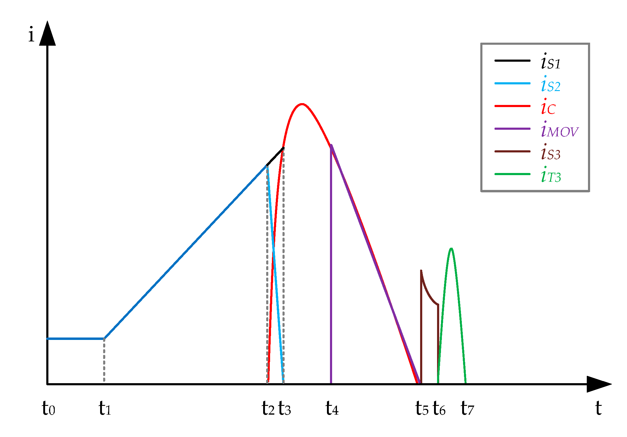
In order to easily understand the operation principle of the proposed HCB, the detailed current waveforms for the positive current interruption are illustrated in Figure 2. The operation of the proposed HCB is divided into eight intervals corresponding to four operation modes. It contains a normal mode (t0~t2) to transfer the power between the sides without any interruption, a breaking mode (t2~t5) to break the fault current, a discharging mode (t5~t6) to reduce the capacitor voltage to the rated voltage, and a reverse mode (t6~t7) to change the capacitor polarity. The detailed operation characteristics of each mode are explained as follows.
2.2.1. Normal Mode (t0~t2)
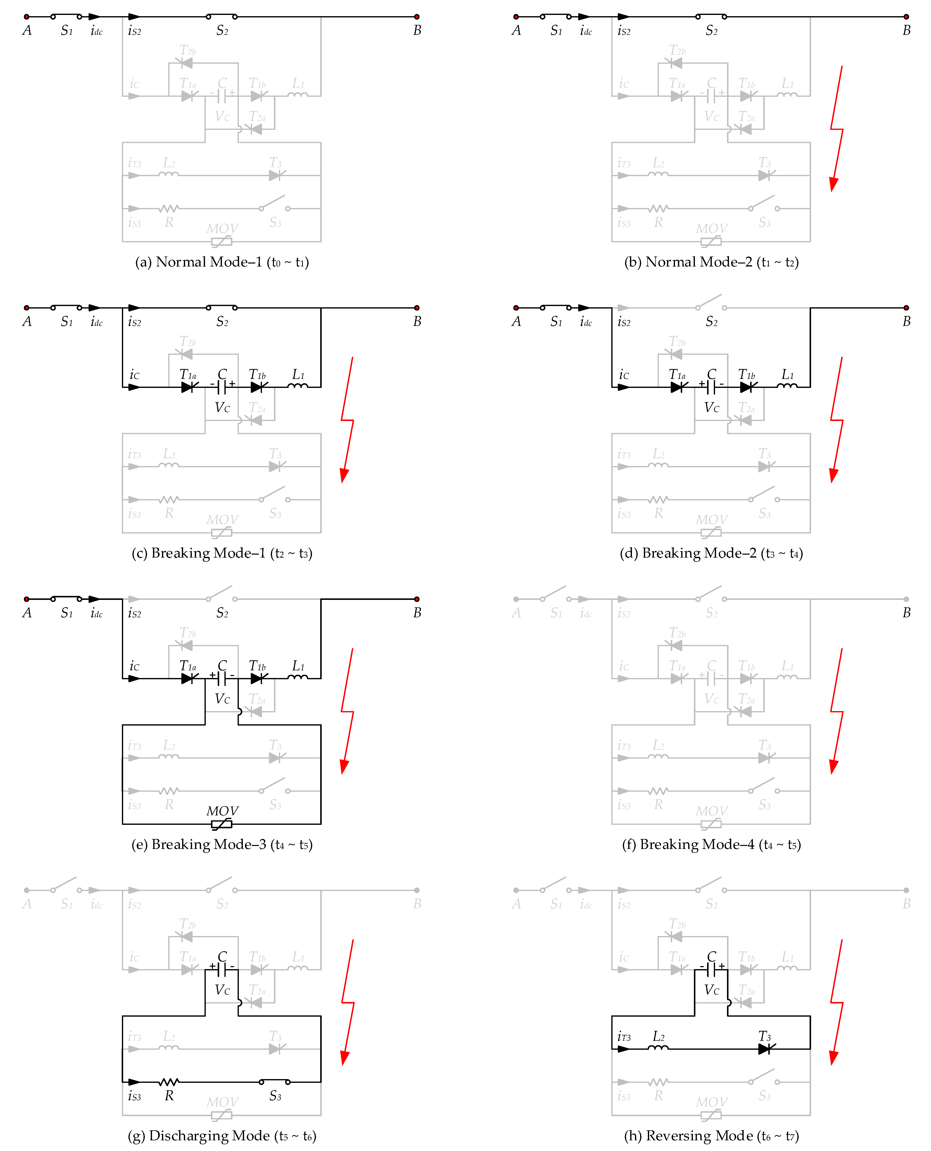
Under normal conditions, the switches S1 and S2 are closed while the switch S3 is opened. Therefore, the DC current between the terminals can stably flow through the main branches on the CB as shown in Figure 3a. The DC current start to increase when a fault occurs at t = t1. At this moment, the normal mode is kept until the DC current is larger than a predefined threshold Itrip to detect a short-circuit fault.
2.2.2. Breaking Mode (t2~t5)
When the DC current reaches a predefined threshold at t = t2, the interruption processes start with opening S2 on the main branch. An electric arc occurs inside the vacuum interrupter of the mechanical switch S2 and the fault current rises continuously while the arc is extinct. Simultaneously, the thyristors (T1a and T1b) are turned-on for the positive current, whereas thyristors (T2a and T2b) are turned-on for negative current, as shown in Figure 3c and Figure 4c. Therefore, the inverse current generated by the resonance circuit including the inductor L1 and capacitor C is injected to the main branch. Due to this, the arc current on the main branch is rapidly decreased and naturally dissipated with the zero crossing of the current at t = t3. In addition, the fault current is completely commutated from the main branch to the auxiliary branch with capacitor C, as shown in Figure 3d and Figure 4d. Subsequently, the fault current oscillates by the capacitor C and inductor L1. The MOV starts to absorb the fault current at t = t4 when the voltage of the capacitor C is over the protection level, as shown in Figure 3e and Figure 4e. At t = t5, when the fault current reaches to zero, the thyristors (T1a and T1b) are turned-off for the positive fault current, whereas thyristors (T2a and T2b) are turned-off for negative fault current, as shown in Figure 3f and Figure 4f. Finally, the DC circuit is isolated by turning-on the residual DC current disconnector S1.
2.2.3. Discharging Mode (t5~t6)
Although the voltage of the capacitor C is protected by the MOV, the overcharged voltage of capacitor C is not suitable for the reclosing operation. Therefore, the loop circuit with the resistor R is used to recover to magnitude of the rated voltage by turning-on the fast mechanical switch S3. During the period of t = t5~t6, the capacitor voltage VC is discharged to magnitude of the rated voltage.
2.2.4. Reversing Mode (t6~t7)
For the reclosing operation, the voltage polarity of the capacitor C should also be changed to the initial condition. Therefore, the reverse capacitor mode is done for the period of t = t6~t7 by turning-on thyristor T3. After this time, the proposed HCB can be reclosed on the DC circuit and have the rebreaking capability by repeating the above operation modes.
2.3. Design Parameters
The component parameters in the proposed topology should be properly designed to successful interrupt the fault current. The operation time and interruption capability of the proposed HCB can affect the circuit parameters. In the following sub-sections, the process of designing parameters is explained in detail below.
2.3.1. Design of Auxiliary Branch with L1-C
During the breaking operation, the injected current from the auxiliary branch with L1-C should be higher than the main branch. The injected current can be obtained as follows:
where is the pre-charging voltage of the capacitor.
From Equation (1), the maximum magnitude of the injected current is . Assuming the minimum injected current for successful interruption of the fault current, the time taken by the injected current to reach the fault current is equal to corresponding to a quarter of the period the injected current. Therefore, the relationship between the inductance and the capacitance C can be represented as follow:
where is the predefined threshold to detect the fault, is the margin of the breaking current, and is the time that the fault current is equal to the injected current. The should be decided within 1 milliseconds by considering the rate of the fault current rise.
Rearranging the Equations (2) and (3), the inductance and the capacitance C are obtained as follows:
2.3.2. Design of Auxiliary Branches with R and L2
The auxiliary branches with R and are used to recover the capacitor voltage to the initial voltage. The parameters can be obtained as follow:
where is the time taken by the discharging mode and is the time taken by the reversing mode.
2.3.3. Design of Energy Absorbing Branch
The MOV is used to protect the capacitor overvoltage by absorbing the energy on the DC circuit. The energy absorbed by the MOV can be represented as follow [24]:
where is the protection voltage level, is the time for absorbing the energy, and is the fault current.
3. Switching Control Algorithm for Proposed HCB
3.1. Outline of the Switching Control Algorithm
The operation mode of proposed HCB is shown in Figure 5. The main components of the control method are divided into two parts. First is the checking mode part and second is the mode selector part. In mode checking, the present operation mode of the HCB is recognized by measuring the DC line current and capacitor voltage. In addition, the function to detect any fault is also included to activate the HCB. From the data of the checking mode, a control unit is required to select the operation mode and control signals. Hence, the real signal of switching state is transferred to each switch by considering the time delay of the real devices. The time delay was considered as 2 ms for the fast mechanical switch and 20 ms for the residual switch [26]. In case of the switch based on the semiconductor, the time delay can be neglected because the switching time is short (0–40 μs) [22]. Therefore, the time delay of the mechanical switch is only considered in the simulation model to reflect the characteristics of real devices.
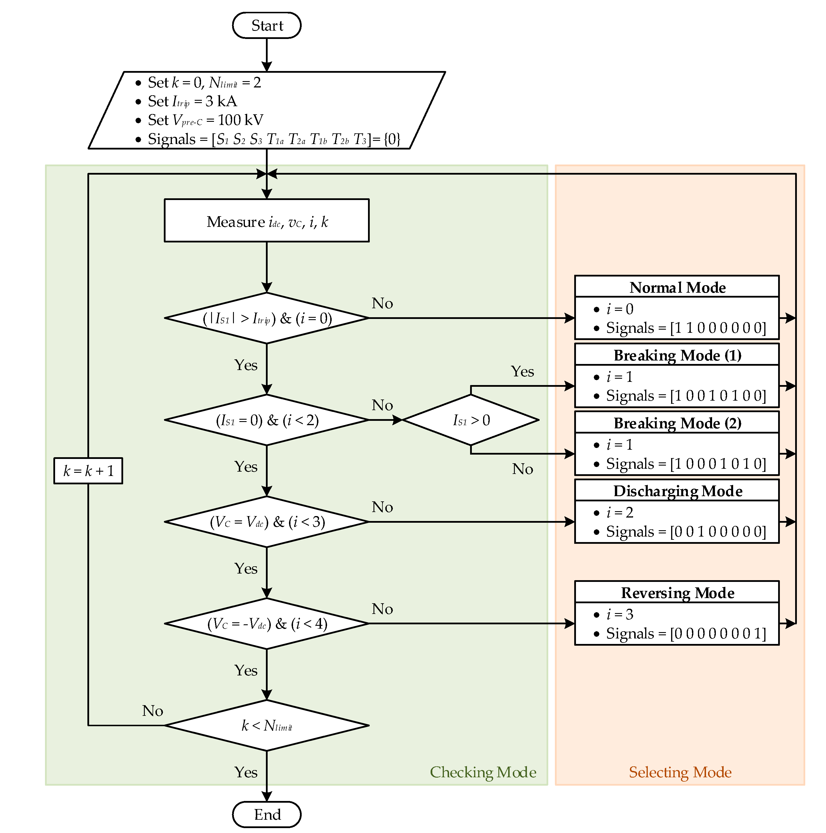
3.2. Flowchart of the Switching Control Algorithm
It is important for the controller to accurately detect the operation status of the HCB as well as the fault depending on the direction of the current. Figure 6 shows the switching control algorithm of the HCB that includes the checking mode and the selecting mode. The variable k is used for limiting the number of the operation of the HCB (Nlimit = 2). The fault can be detected by the predefined threshold Itrip to detect the fault. The two measurement signals, DC line current and the capacitor voltage, are required for the algorithm. The detailed procedures of the switching control algorithm are shown as follows.
- Initially, the number of the operation of HCB and the threshold for detecting the fault are determined. After closing HCB in the normal mode, the control system checks the operation mode of the HCB by measuring the DC line current and capacitor voltage.
- If the magnitude of the DC line current is higher than the predefined threshold, the fault is detected and the direction of the fault current is determined (positive or negative). At the same time, the proper breaking mode is selected according to the direction of the fault current. For example, the breaking mode is active by turning on the thyristors (T1a and T1b) for the forward direction and the thyristors (T2a and T2b) for the reverse direction. The breaking mode is kept until the DC line current is dropped to zero.
- The DC line can be isolated by the HCB after the breaking mode. Considering the reclosing operation of the HCB, the capacitor voltage is checked whether the magnitude and polarity is same with the pre-charged voltage. If capacitor voltage is not equal to the pre-charged value, the capacitor voltage is controlled by the discharging mode and reversing mode.
- The HCB can be reclosed shortly after the reversing mode is passed. However, the number of the reclosing the HCB can be restricted by operating sequence: open–close/open–close/open (O–CO–CO) [25].
4. Simulation Results
4.1. Test System for Case Studies
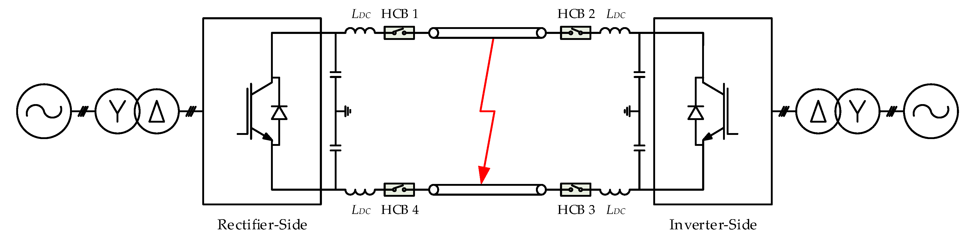
In order to test the performance of the proposed HCB, a symmetrical monopole VSC-HVDC was modeled in MATLAB/Simulink, as illustrated in Figure 7. The AC network next to the HVDC link is substituted by an equivalent resistor (R)–inductor (L) impedance, which enabled the X/R ratio of the power system to be determined. The converter transformer is a wye-delta connection. A phase reactor is added between the converter and transformer to filter the harmonics during conversion. Each HCB is located at the output of both the rectifier and inverter sides. The detail specifications of the HVDC link are as follows [27]: the rated voltage () = ±100 kV, nominal current () = 1 kA, nominal power flow () = 200 MW, DC reactor () = 50 mH, and the transmission line length = 100 km.
The basic parameters of the designed HCB topology are summarized in Table 2. Four HCBs are applied to the positive and negative pole at each side. The mechanical switches in the HCB are considered as the breaker blocks provided by MATLAB/Simulink. The arc extinction process is modeled by opening the mechanical switches when its current passes through 0 at the first current zero crossing.
The simulations are carried out under two different scenarios to verify the performances of the proposed HCB. The first scenario is under the temporary fault while the second scenario is under permanent fault on the middle of the DC transmission line at 0.5 s.
4.2. Temporary Fault on DC Line
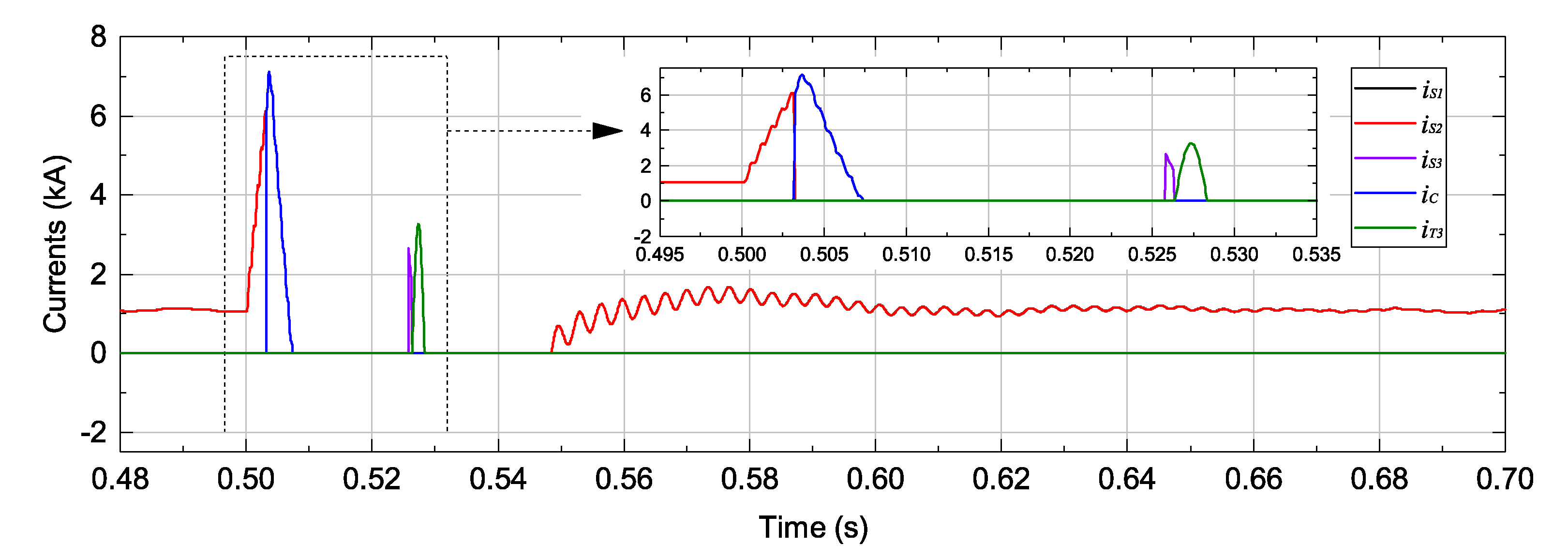
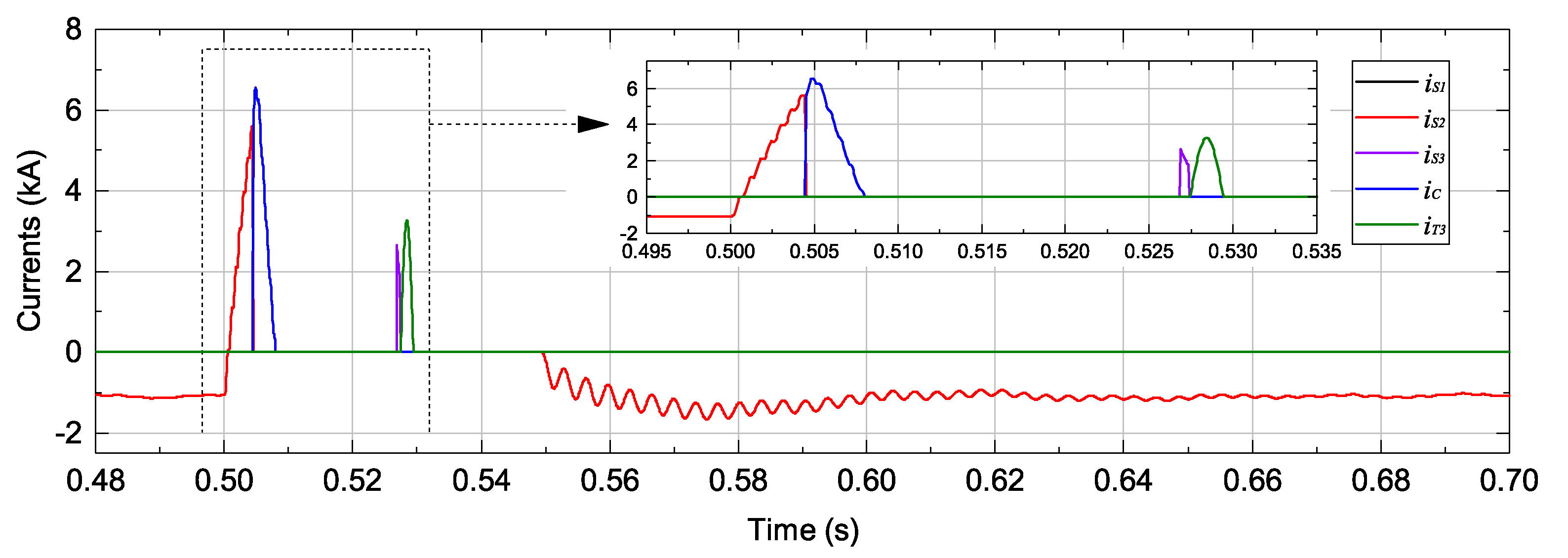
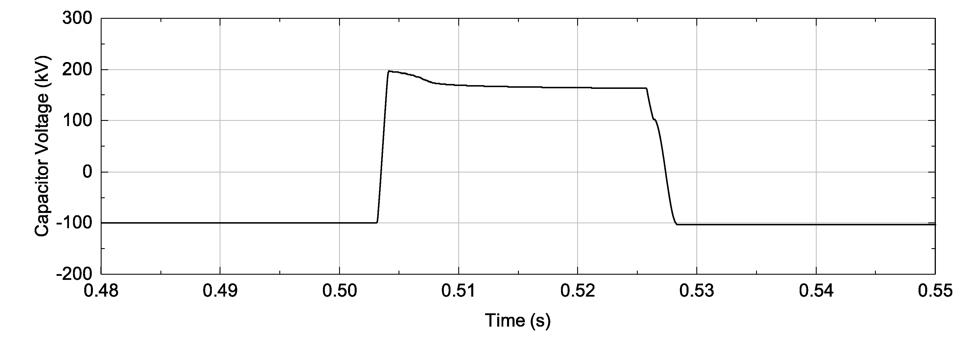
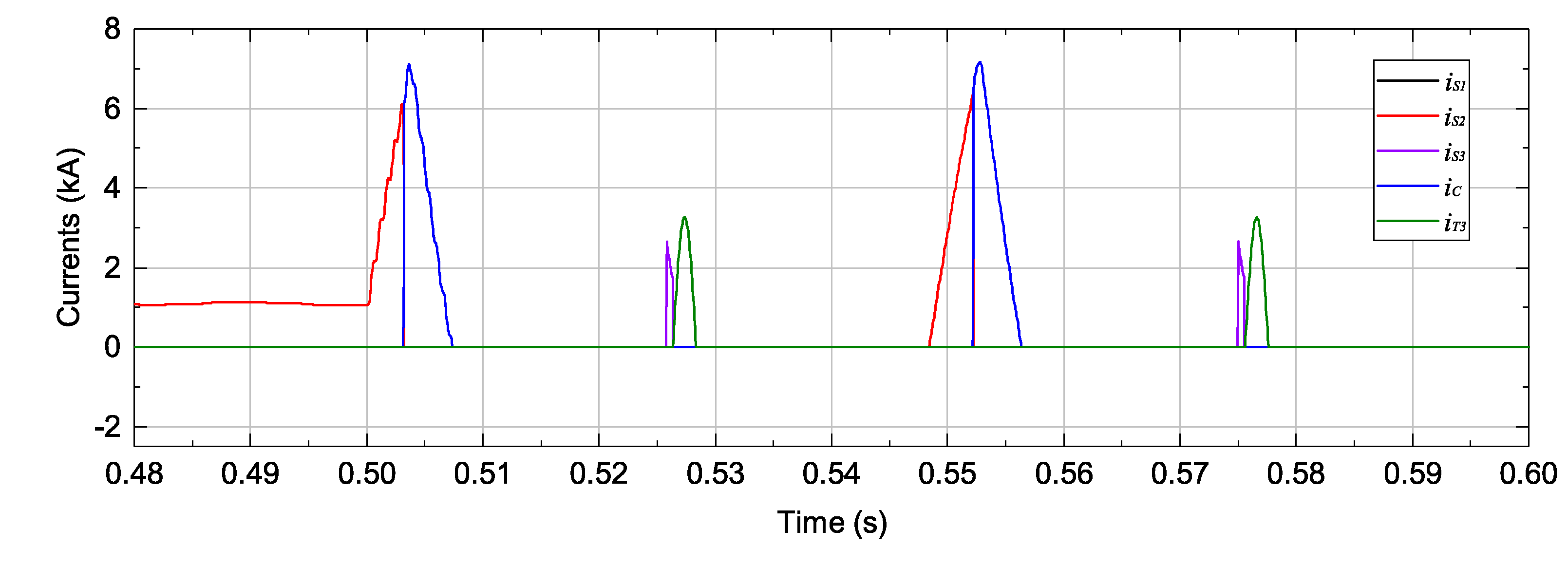
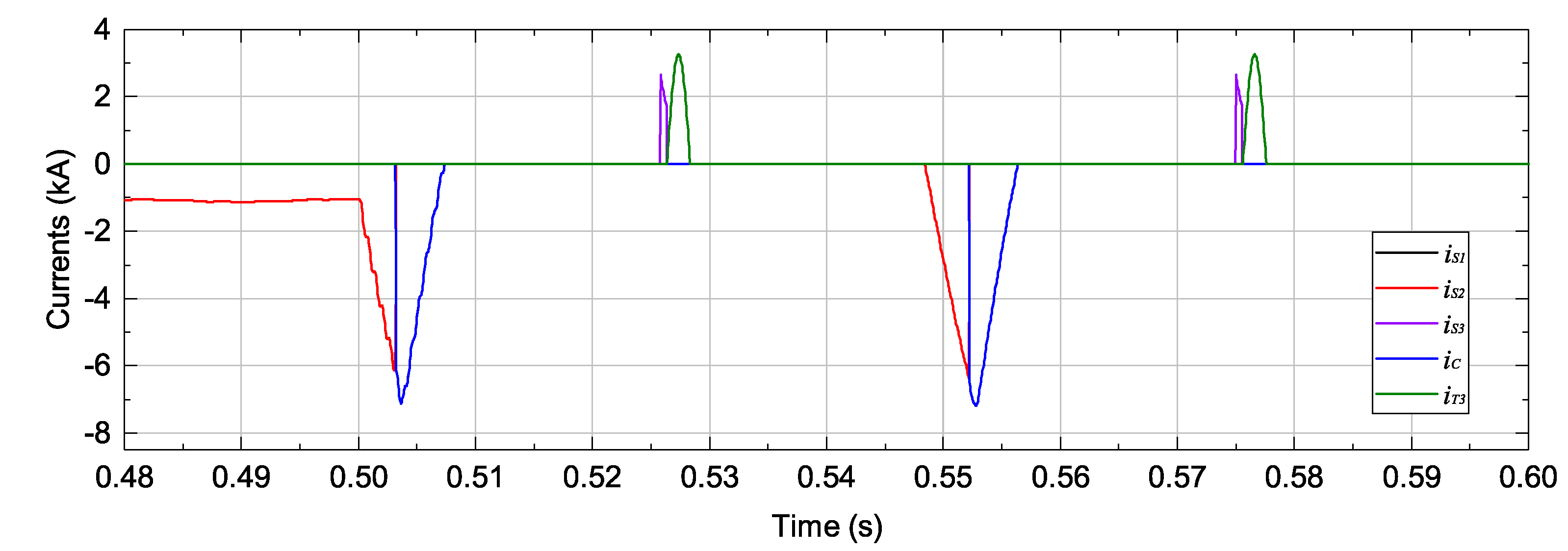
The current and capacitor voltage waveforms of the proposed HCBs during a temporary fault are shown in Figure 8, Figure 9, Figure 10, Figure 11 and Figure 12. Under normal conditions, the current direction on the positive pole is from rectifier to inverter while the current direction on the negative pole is opposite. It is assumed that the fault occurs at 0.5 s and it is cleared from the HVDC system after 5 ms. The DC current is increased due to the short circuit. The fault currents flow from both sides to the fault location. At this moment, the fault is detected when the fault current reaches the positive threshold for HCB 1 and HCB 3 and the negative threshold for HCB 2 and HCB 4. After detecting the fault, the turn-off signal is transferred to switch S2 in each HCB. At the same time, the thyristors (T1a and T1b) in HCB 1 and HCB 3 are turned-on while the thyristors (T2a and T2b) in HCB 2 and HCB 4 are turned-on. The current on the auxiliary branch with thyristors (T1a and T1b or T2a and T2b) is injected to the branch with L1-C. Therefore, the current on the switch S2 is naturally dissipated because the current on the branch with the switch S2 reaches to zero. After that, the fault current flows through the auxiliary and is fully dissipated at about 0.5074 s. During breaking operation, the capacitor voltages in each HCB are increased to the protection level of MOV and the polarity is opposite to the initial condition as shown in Figure 11. In order to reclose the DC line, the capacitor voltage through the auxiliary branches with R-C and L2-C is reversed after the time delay of S1. At t = 0.5284 s, the reverse voltage mode of the HCBs is conducted and HVDC system is recovered to the normal mode by reclosing the HCBs.
4.3. Permanent Fault on DC Line
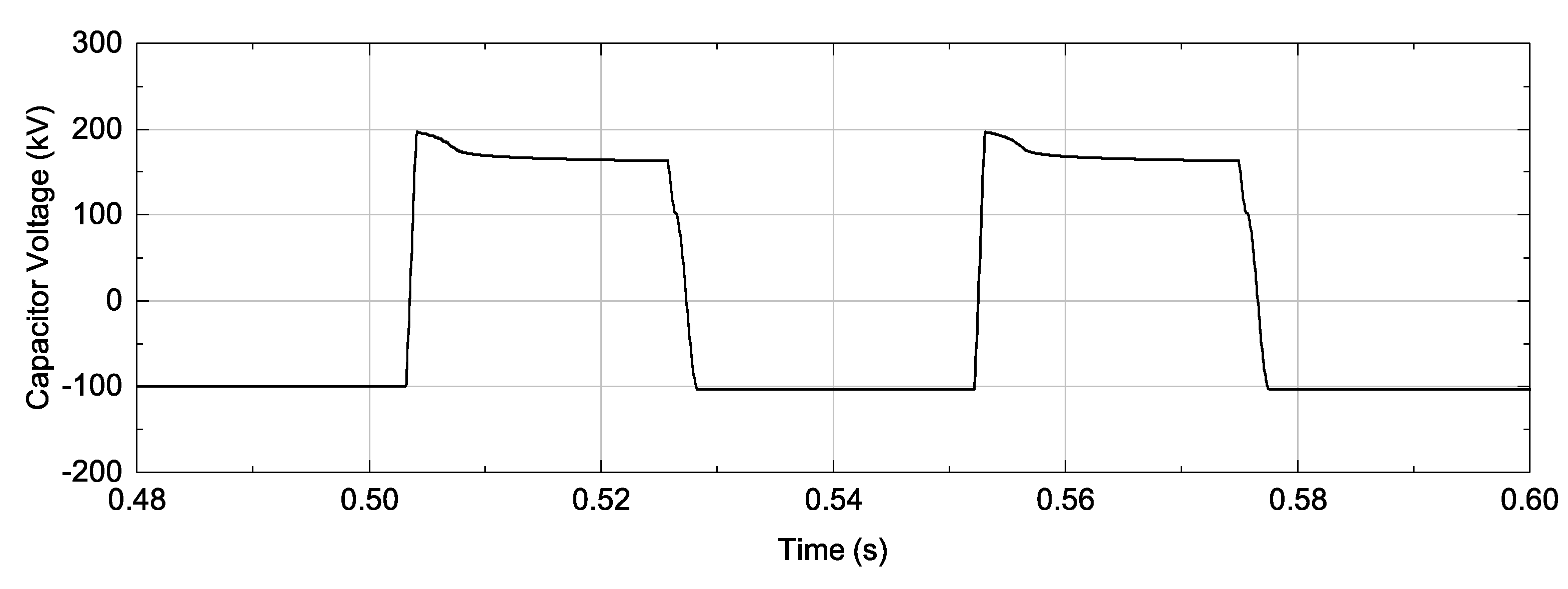
After the initial fault current is cleared with a typical temporary fault, the reclosing and rebreaking operations are carried out continuously with the proposed HCB. The current and capacitor voltage waveforms of fours the HCBs in a typical permanent fault condition are illustrated in Figure 13, Figure 14, Figure 15, Figure 16 and Figure 17. The reclosing operation of the HCBs is started at 0.5274 s after the delay time by turned-off switch S1. For this operation, the discharging and reversing capacitor voltage modes are performed and are finished at 0.5284 s. After this time, the HCBs allow the rebreaking operation by reclosed the switch S1. The rebreaking operation of the HCBs begins at 0.5484 s after 20 ms the delay time of switch S1. The procedure to rebreak the fault current is same operation in case of the temporary fault. Hence, the fault current interruption repeatedly of the HCBs is done at 0.5558 s. In order to fulfil the operation of the HCBs, the voltage of the capacitor (C) is recovered to the normal condition by the implementation of the discharging and reversing modes again. This process takes 10 ms after a delay time of turned-off switch S1 at 0.5758 s. At 0.5768 s, the operation of HCBs for a typical permanent fault condition is completed. In addition, the peak fault current is limited at 7 (kA) and the operation time to break fault current is 5 ms in both the process of fault current interruption.
5. Conclusions
This paper proposed a novel topology of HCB with the capabilities of bidirectional fault current interruption, reclosing, and rebreaking. In addition, a switching control algorithm for the HCBs was developed to operate the proposed HCB in different operation modes, such as the normal mode, breaking mode, discharging mode, and reversing the capacitor after clearing the fault. The simulation results showed that the HVDC system could be recovered by reclosing the HCB for the temporary fault. In the case of the permanent fault, the proposed HCB could interrupt the fault current continuously. The reclosing and rebreaking capabilities of the proposed HCB could supply the benefit of reliable and safe operation of the HVDC grid. The proposed HCB has lower on-state losses than the semiconductor-based HCB such as ABB HCB due to the use of thyristor instead of IGBT. The proposed HCB can reduce the fault interruption time in the case of bidirectional fault interruption because the polarity of the pre-charged capacitor does not change after identifying the direction of the fault current. Simulation results have shown that the fault interruption time of the proposed HCB was about 7 ms, which is about 30% lower than the interruption time of the HCB model in [25] (the interruption time is about 10 ms).
With the capabilities of bidirectional fault current interruption, reclosing, and rebreaking, the proposed HCB topology can be considered a potential solution for the protection of the multi-terminal VSC-HVDC (MTDC) system. Our future work will focus on the testing of the proposed HCB topology in the MTDC system.
Acknowledgments
This research was supported by Korea Electric Power Corporation [grant number: R15XA03-40].
Author Contributions
V.-V.N. conceived and designed the experiments; H.-I.S. and T.-T.N. performed the experiments; H.-M.K. and C.-K.K. revised and analyzed the results; V.-V.N. wrote the paper.
Conflicts of Interest
The authors declare no conflict of interest.
References
- Greenwood, A.; Kanngiessner, K.; Lesclae, V.; Margaard, T.; Schultz, W. Circuit breakers for meshed multiterminal HVDC systems. Part I: Introduction DC side substation switching under normal and fault conditions. Electra 1995, 163, 98–122. [Google Scholar]
- Greenwood, A.; Kanngiessner, K.; Lesclae, V.; Margaard, T.; Schultz, W. Circuit breakers for meshed multiterminal HVDC systems. Part II: Switching of transmission lines in meshed MTDC systems. Electra 1996, 164, 62–82. [Google Scholar]
- Bergstrom, L.; Juhlin, L.E.; Liss, G.; Svensson, S. Simulator study of multiiterminal HVDC system performance. IEEE Trans. Power Appl. Syst. 1978, PAS-97, 2057–2066. [Google Scholar] [CrossRef]
- Kanngiesser, K.; Ring, H.; Wess, T. Simulator study on line fault clearing by DC circuit breakers in a meshed MTDC system. In Proceedings of the International Conference on AC and DC Power Transmission, London, UK, 17–20 September 1991; pp. 102–107. [Google Scholar]
- Franck, C.M. HVDC circuit breakers: A review identifying future research needs. IEEE Trans. Power Deliv. 2011, 26, 998–1007. [Google Scholar] [CrossRef]
- Chaffey, G.; Green, T.C. Reduced DC circuit breaker requirement on mixed converter HVDC networks. In Proceedings of the IEEE Eindhoven PowerTech, Eindhoven, The Netherlands, 29 June–2 July 2015; pp. 1–6. [Google Scholar]
- Saad, H.; Peralta, J.; Dennetiere, S.; Mahseredjian, J.; Jatskevich, J.; Martinez, J.; Davoudi, A.; Saeedifard, M.; Sood, V.; Wang, X.; et al. Dynamic averaged and simplified models for MMC-based HVDC transmission systems. IEEE Trans. Power Deliv. 2013, 28, 1723–1730. [Google Scholar] [CrossRef]
- Ekstrom, A.; Hartel, H.; Lips, H.; Schultz, W.; Joss, P.; Holfeld, H.; Kind, D. Design and Testing of an HVDC Circuit Breaker; CIGRE: Paris, France, 1976. [Google Scholar]
- Belda, N.A.; Smeets, R.P.P. Test circuits for HVDC circuit breakers. IEEE Trans. Power Deliv. 2017, 32, 285–293. [Google Scholar] [CrossRef]
- Ahmed, N. Efficient modeling of an MMC-based multiterminal DC system employing hybrid HVDC breakers. IEEE Trans. Power Deliv. 2015, 30, 1792–1801. [Google Scholar] [CrossRef]
- Sano, K.; Takasaki, M. A surgeless solid-state DC circuit breaker for voltage-source-converter-based HVDC systems. IEEE Trans. Ind. Appl. 2014, 50, 2690–2699. [Google Scholar] [CrossRef]
- Asplund, G. HVDC Grid Feasibility Study Working Group b4-52; CIGRE: Paris, France, 2013; pp. 56–65. [Google Scholar]
- Kim, J.Y.; Choi, S.S.; Kim, I.D. A new reclosing and re-breaking DC thyristor circuit breaker for DC distribution applications. J. Power Electron. 2017, 17, 272–281. [Google Scholar] [CrossRef]
- Mokhberdoran, A.; Carvalho, A.; Leite, H.; Silva, N. A review on HVDC circuit breakers. In Proceedings of the 3rd Renewable Power Generation Conference (RPG 2014), Naples, Italy, 24–25 September 2014; pp. 1–6. [Google Scholar]
- Shukla, A.; Demetriades, G.D. A survey on hybrid circuit-breaker topologies. IEEE Trans. Power Deliv. 2015, 30, 627–641. [Google Scholar] [CrossRef]
- Tokoyoda, S.; Sato, M.; Kamei, K.; Yoshida, D.; Miyashita, M.; Kikuchi, K.; Ito, H. High frequency interruption characteristics of VCB and its application to high voltage DC circuit breaker. In Proceedings of the 2015 3rd International Conference on Electric Power Equipment; Switching Technology (ICEPE-ST), Busan, Korea, 25–28 October 2015; pp. 117–121. [Google Scholar]
- Corzine, K.A. A new-coupled-inductor circuit breaker for DC applications. IEEE Trans. Power Electron. 2017, 32, 1411–1418. [Google Scholar] [CrossRef]
- Keshavarzi, D.; Ghanbari, T.; Farjah, E. A Z-source based bidirectional DC circuit breaker with fault current limitation and interruption capabilities. IEEE Trans. Power Electron. 2017, 32, 6813–6822. [Google Scholar] [CrossRef]
- Maqsood, A.; Overstreet, A.; Corzine, K.A. Modified Z-source DC circuit breaker topologies. IEEE Trans. Power Electron. 2016, 31, 7394–7403. [Google Scholar] [CrossRef]
- Mokhberdoran, A.; Carvalho, A.; Silva, N.; Leite, H.; Carrapatoso, A. A new topology of fast solid-state HVDC circuit breaker for offshore wind integration applications. In Proceedings of the 17th European Conference on Power Electronics and Applications (EPE’15 ECCE-Europe), Geneva, Switzerland, 8–10 September 2015; pp. 1–10. [Google Scholar]
- Hafner, J.; Jacobson, B. Proactive hybrid HVDC breakers—A key innovation for reliable HVDC grids. In Proceedings of the Electric Power System of the Future—Integrating Supergrids and Microgrids International Symposium, Bologna, Italy, 13–15 September 2011; pp. 1–9. [Google Scholar]
- Lin, W.; Jovcic, D.; Nguefeu, S.; Saad, H. Modelling of high-power hybrid DC circuit breaker for grid-level studies. IET Power Electron. 2016, 9, 237–246. [Google Scholar] [CrossRef]
- Liu, G.; Xu, F.; Xu, Z.; Zhang, Z.; Tang, G. Assembly HVDC breaker for HVDC grids with modular multilevel converters. IEEE Trans. Power Electron. 2017, 32, 931–941. [Google Scholar] [CrossRef]
- Feng, L. A 320 kV hybrid HVDC circuit breaker based on thyristors forced current zero technique. In Proceedings of the IEEE Applied Power Electronics Conference and Exposition (APEC), Tampa, FL, USA, 26–30 March 2017; pp. 384–390. [Google Scholar]
- Kim, B.C.; Chung, Y.H.; Hwang, H.D.; Mok, H.S. Comparison of inverse current injecting HVDC curcuit breaker. In Proceedings of the 3rd International Conference on Electric Power Equipment–Switching Technology (ICEPE-ST), Busan, Korea, 25–28 October 2015; pp. 501–505. [Google Scholar]
- Khan, U.A. A novel model of HVDC hybrid-type superconducting circuit breaker and its performance analysis for limiting and breaking DC fault currents. IEEE Trans. Appl. Supercond. 2015, 25, 5603009. [Google Scholar] [CrossRef]
- Lee, J.G.; Khan, U.A.; Lee, H.Y.; Lee, B.W. Impact of SFCL on the four types of HVDC circuit breakers by simulation. IEEE Trans. Appl. Supercond. 2016, 26, 5602606. [Google Scholar] [CrossRef]
Figure 1.
The proposed bidirectional hybrid circuit breaker (HCB) topology.

Figure 2.
Current waveforms of the proposed HCB topology.

Figure 3.
Operating modes of the proposed HCB topology with DC fault at the B-side.

Figure 4.
Operating modes of the proposed HCB topology with DC fault at the A-side.
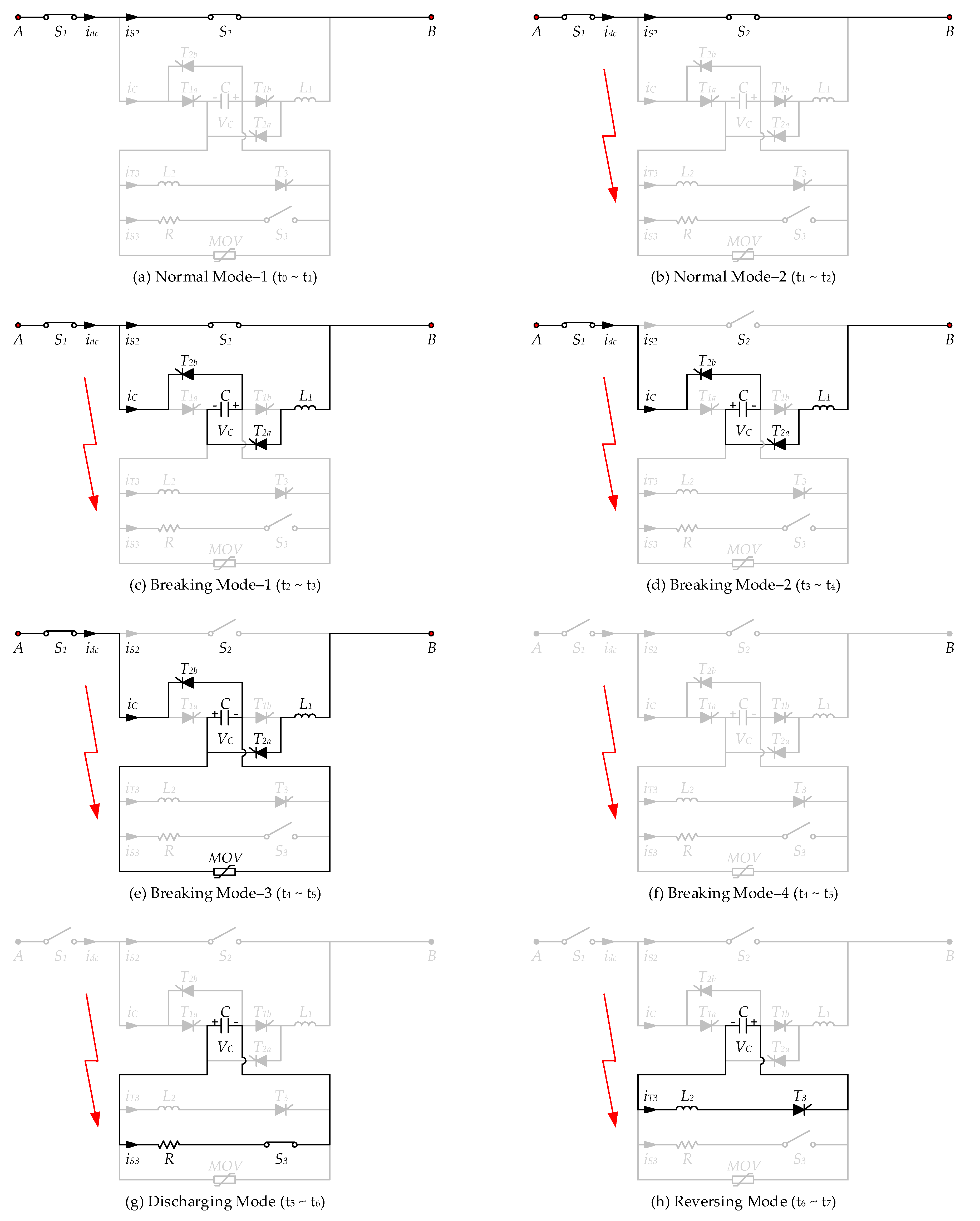
Figure 5.
Operation mode of proposed HCB topology.
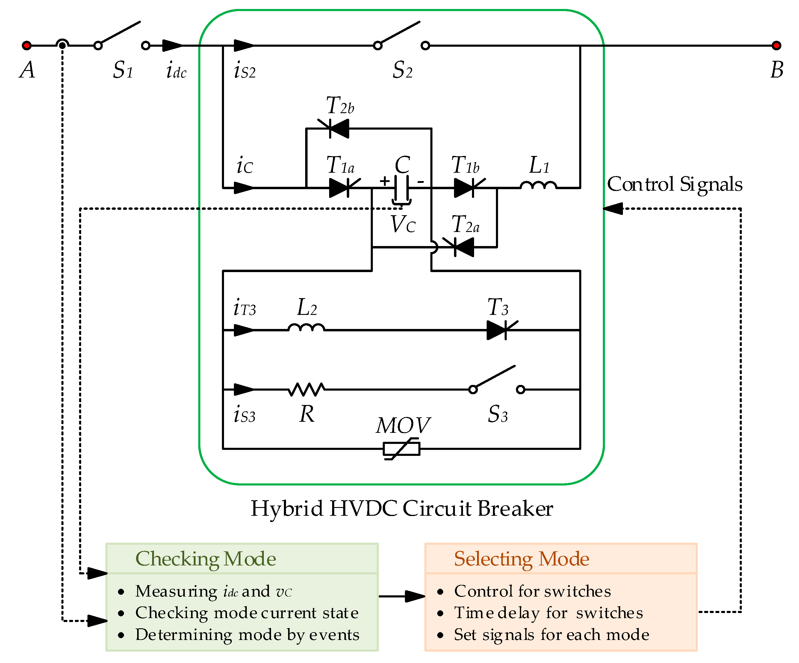
Figure 6.
Flowchart of the switching control algorithm for the proposed HCB topology.

Figure 7.
Configuration of the voltage source converter-based high voltage direct current (VSC-HVDC) model.
Figure 7.
Configuration of the voltage source converter-based high voltage direct current (VSC-HVDC) model.

Figure 8.
Overall currents on the switches of HCB 1.

Figure 9.
Overall currents on the switches of HCB 2.
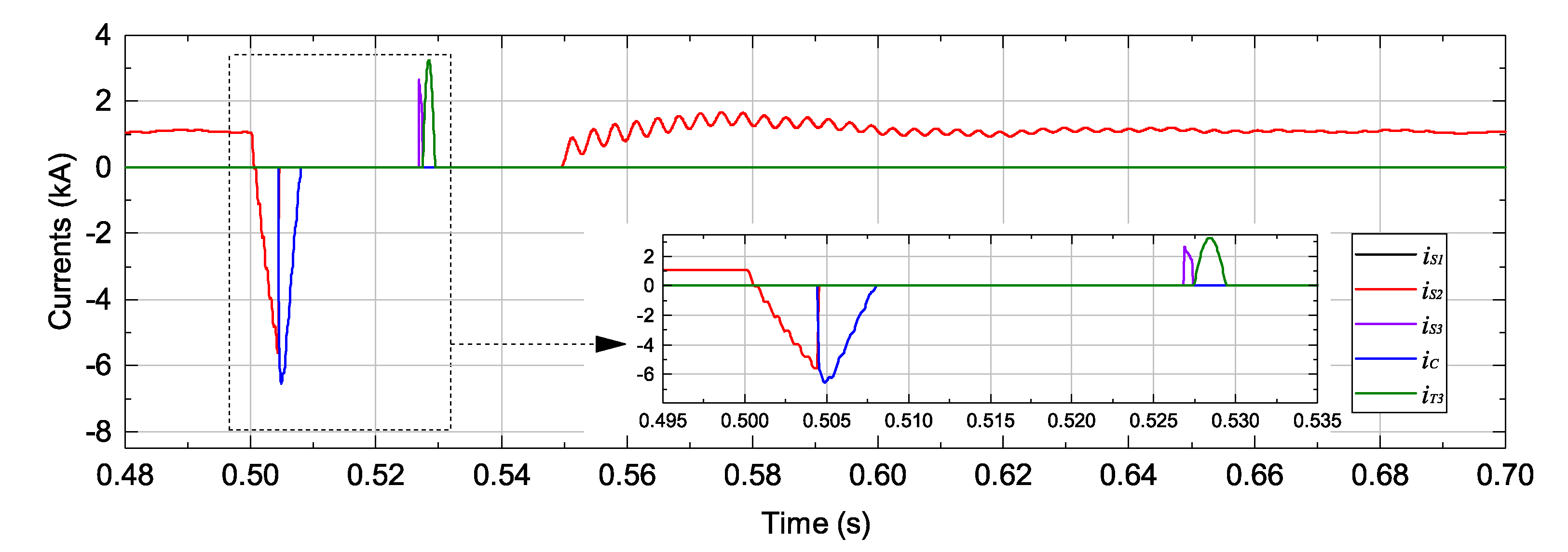
Figure 10.
Overall currents on the switches of HCB 3.

Figure 11.
Overall currents on the switches of HCB 4.
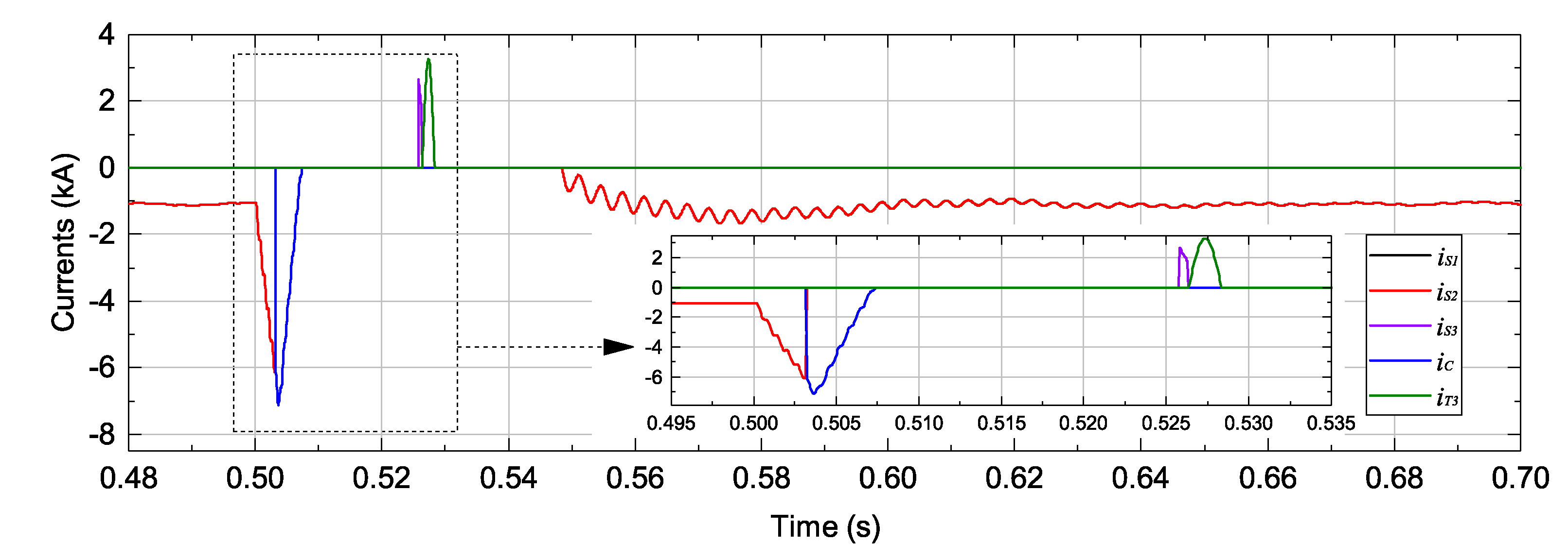
Figure 12.
Capacitor voltage in the proposed HCB.

Figure 13.
Overall currents on the switches of HCB 1.

Figure 14.
Overall currents on the switches of HCB 2.
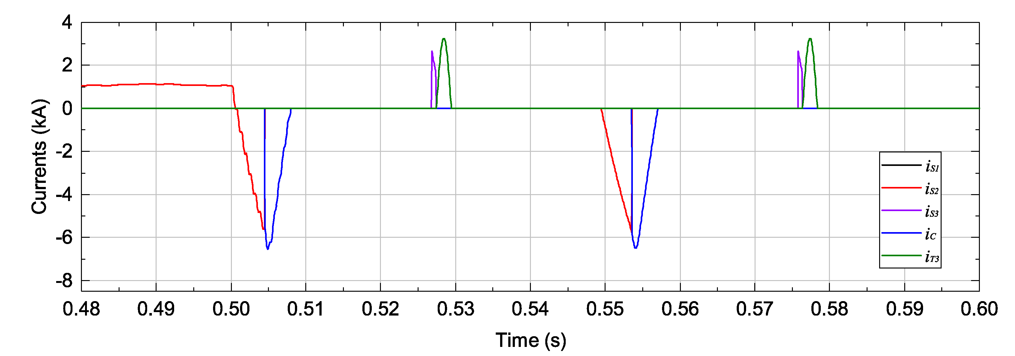
Figure 15.
Overall currents on the switches of HCB 3.

Figure 16.
Overall currents on the switches of HCB 4.

Figure 17.
Capacitor voltage in the proposed HCB.


Table 1.
Switching states for positive and negative current scenarios.
| Positive Currents | ||||||||
| Modes | S1 | S2 | S3 | T1a | T2a | T1b | T2b | T3 |
| Normal Mode | 1 a | 1 | 0 | 0 | 0 | 0 | 0 | 0 |
| Breaking Mode | 1 | 0 | 0 | 1 | 0 | 1 | 0 | 0 |
| Discharging Mode | 0 b | 0 | 1 | 0 | 0 | 0 | 0 | 0 |
| Reversing Mode | 0 | 0 | 0 | 0 | 0 | 0 | 0 | 1 |
| Negative Currents | ||||||||
| Modes | S1 | S2 | S3 | T1a | T2a | T1b | T2b | T3 |
| Normal Mode | 1 | 1 | 0 | 0 | 0 | 0 | 0 | 0 |
| Breaking Mode | 1 | 0 | 0 | 0 | 1 | 0 | 1 | 0 |
| Discharging Mode | 0 | 0 | 1 | 0 | 0 | 0 | 0 | 0 |
| Reversing Mode | 0 | 0 | 0 | 0 | 0 | 0 | 0 | 1 |
a 1 represents for the closed or turned-on state; b 0 represents for the opened or turned-off state.
Table 2.
HCBs parameters.
| Parameters | Symbol | Specifications |
|---|---|---|
| Capacitor | C | 20 µF |
| Inductance 1 | L1 | 1 mH |
| Inductance 2 | L2 | 20 mH |
| Resistance | R | 60 Ω |
| Time delay of residual switch | TS1 | 20 ms |
| Time delay of mechanical switch | TS2 | 2 ms |
© 2017 by the authors. Licensee MDPI, Basel, Switzerland. This article is an open access article distributed under the terms and conditions of the Creative Commons Attribution (CC BY) license (http://creativecommons.org/licenses/by/4.0/).
Share and Cite
MDPI and ACS Style
Nguyen, V.-V.; Son, H.-I.; Nguyen, T.-T.; Kim, H.-M.; Kim, C.-K. A Novel Topology of Hybrid HVDC Circuit Breaker for VSC-HVDC Application. Energies 2017, 10, 1675. https://doi.org/10.3390/en10101675
AMA Style
Nguyen V-V, Son H-I, Nguyen T-T, Kim H-M, Kim C-K. A Novel Topology of Hybrid HVDC Circuit Breaker for VSC-HVDC Application. Energies. 2017; 10(10):1675. https://doi.org/10.3390/en10101675
Chicago/Turabian StyleNguyen, Van-Vinh, Ho-Ik Son, Thai-Thanh Nguyen, Hak-Man Kim, and Chan-Ki Kim. 2017. "A Novel Topology of Hybrid HVDC Circuit Breaker for VSC-HVDC Application" Energies 10, no. 10: 1675. https://doi.org/10.3390/en10101675
Note that from the first issue of 2016, this journal uses article numbers instead of page numbers. See further details here.