Using IEC 61850 GOOSE Service for Adaptive ANSI 67/67N Protection in Ring Main Systems with Distributed Energy Resources


1
Schneider Electric, Energy, 08019 Barcelona, Spain
2
La Salle—Ramon Llull University, GRITS—Research Group in Internet Technologies and Storage, 08022 Barcelona, Spain
*
Author to whom correspondence should be addressed.
Energies 2017, 10(11), 1685; https://doi.org/10.3390/en10111685
Submission received: 28 August 2017
/
Revised: 17 October 2017
/
Accepted: 19 October 2017
/
Published: 25 October 2017
(This article belongs to the Special Issue Control and Communication in Distributed Generation Systems)
Abstract
:Smart Grids are electricity networks that use digital technology to co-ordinate the needs and capabilities of all generators, grid operators, end users and electricity market stakeholders in such a way that it can optimize asset utilization and operation while maintaining system reliability, resilience and stability. However, Smart Grids are increasingly proposing a much more distributed architecture with the integration of multiple Distributed Energy Resources (DERs) that demand different control and protection schemes. In that sense, the implementation of standards such as IEC 61850 and the integration with Ethernet-based communication networks provide novel tools to manage DER efficiently. This paper analyses the potential usage and benefits of ANSI 67/67N protection in combination with Generic Object Oriented Substation Event (GOOSE) communication service, from the standard 61850 of the International Electro-technical Commission (IEC), for providing adaptive network protection, specifying the configuration and implementation and exposing the obtained results.
1. Introduction
The concept of Smart Grids has been considered in the last years as the appropriate answer to address the new challenges in the energy domain: network reliability, energy efficiency, distributed renewable energy sources and the increasing network complexity. However, multiple barriers appear in the road to realize these achievements. Proactive operation of the grid, efficient integration of demand and renewable generation into grid operation, or the integration of Smart Grids with other energy networks still need additional resources to get applicable solutions.
Moreover, the increasing penetration of Distributed Energy Resources (DERs) demands the evolution of the traditional control and protection schemes of electrical energy systems. Traditional protection schemes are evolving in new functionalities thanks to the emergence of standards such as IEC 61850 and the usage of Ethernet-based communication capabilities. They are necessaries to success in new electrical energy system topologies that are coming with the increasing penetration of renewal energy sources distributed around the Smart Grid.
The protection relays’ evolution to the current Intelligent Electronic Devices (IEDs), which include measurement, protection, control, fault recording and reporting, allows fast and efficient system management. That is possible because of their capability for providing and communicating more data and increasing the Smart Grid distributed automation versus the traditional centralized nodes.
Research work has been presented in [1] proposing the application of IEDs and their communications capabilities on traditional protection schemes. Indeed, there is a research trend focused in the evolution of Fault Location, Isolation and Restoration System (FLIRS) applications and adaptive protection schemes as a part of the automation in the future smart grids and micro-grids. Several research articles [2,3,4,5] have revealed projects developing self-healing functionality in mesh grids after a fault location using IEC 61850 services in directional protection schemes. All these functions are included in Advanced Distributed Automation (ADA) systems, which are necessaries to cover the increasing penetration of DER in the grids.
In previous research steps, the authors worked on the analysis of different communications options for efficient and flexible deployment of novel Smart Grid services at the distribution level towards the Software-Defined Utility (SDU) concept [6], with the objective of obtaining a higher software-based and automated management of the grid and reducing its operational cost. As stated in [6], SDU strategies send messages with stringent reliability demands between different points of the electrical distribution network with delay requirements of a few milliseconds, which force the communication network to react in a similar response time in case of failure. Thus, many of the SDU services have stringent requirements in terms of availability and delay [6,7]. For example, in the European project FINESCE, SDU claims are not always considering their extension to the power distribution network and thus they were confined to the primary substation. This was mostly due to the difficulties arisen from the distributed, complex and partly buried nature of the distribution network in addition to its partially meshed physical topology. To bridge this challenging gap, distribution network requirements has been defined according to the analysis performed on IEC 61850 among others. From the main master lines of the SDU developments, the authors stress on coping with the stringent Smart Grid ICT requirements and allowing the easy deployment of distributed applications over the grid by following existing standards as much as possible. An example of the SDU paradigm pursues to extend the Primary Substation protocols to its surrounding distribution area by creating an IEC 61850 centric system that allows to consider the defined area as a virtual substation from the communications point of view. Following this line of thought, the approach proposed in [7] for communications over the distribution network is to focus on the development of a novel and flexible ICT infrastructure based on a mix of heterogeneous Ethernet link layer technologies.
Previous articles [6,7] have disclosed that intelligent electronic devices operating with the IEC 61850 protocol and that any other protocols for accessing data are translated to the mentioned protocol before storing the data in the repositories. The enablement of Generic Object Oriented Substation Event (GOOSE) messages defined in the IEC 61850 standard in the whole domain is also relevant, even outside of the Primary Substation. In [7], it was highlighted that the low latency and very high reliability needed for Active Protection Functions can be difficult to achieve with the GOOSE protocol. However, it also remarked the high reliability needed for Command & Regulations and Monitoring & Analysis functional classes, which are not easy to achieve in practice in a distribution grid environment over Ethernet protocol. In summary, although there are some publications such as [8], which presented a method that can communicate several nodes in a microgrid by means of IEEE Time Sensitive Networking and GOOSE messages, the demonstration of GOOSE capabilities in these concerns is still an uncompleted scientific study regarding the communication in a SDU paradigm.
Taking into account this background, this paper focuses on validating and evaluating the usage of IEC 61850 in the configuration and deployment of phase directional protection and earth fault directional protection cases, respectively called 67 and 67N in ANSI codes. Notwithstanding, although it focused in these specific cases, it also represents a very valuable study for the SDU deployment, exploring how IEC 61850 GOOSE service can be configured and applied to different protection cases, but also provides a proof-of-concept of how other SDU applications could be adapted for running with a communications layer directly over Ethernet.
The rest of the paper is organized as follows: Section 2 introduces the directional protection, ANSI 67/67N and details its usage over 3-phase systems. Section 3 summarizes the different models and services provided by the IEC 61850 standard, presents the potential usage in combination with ANSI 67/67N for adaptive protection of electrical systems with DER and reviews related work of this research topic. Section 4 specifies the configuration and implementation process of the testbed, and Section 5 exposes and analyses the obtained results. Finally, Section 6 presents some conclusions and further work to be undertaken.
2. Directional Protection
This section describes the meaning of ANSI 67/67N protection and the potential of directional protection in 3-phase systems using the GOOSE service of the IEC 61850 standard. Distribution line protection can use any of the following principles [9]:
- Directional overcurrent protection: The overcurrent protection can be given directional features by adding directional element in the protection system. Directional overcurrent protection responds to an overcurrent for a particular direction flow.
- Directional comparison protection: Directional comparison protection can work with any high-speed, dedicated channel. Channel impairments may affect scheme dependability or security, depending upon the scheme logic (tripping or blocking logic).
- Current differential protection: Line current differential protection compares current information from the line terminals over the communications channel. Phase comparison protection only compares current phase angle information, which reduces the channel bandwidth requirements. Line current differential protection is secure and more dependable than other types of protection in response to the effects of unbalances, power swings, mutual coupling, and voltage inversion.
2.1. ANSI 67/67N (Fault Directional Protection)
ANSI 67/67N protection has diverse applications like main protection of aerial lines and cables, of transformers of distribution, motors among many others. Usually it is also used as backup protection for power transformers and large generators and as emergency protection for distance protections and line differentials. In power transformers connected in parallel and in parallel lines fed by one end, overcurrent protections need the criterion of directionality to be selective. In these cases, the measurement of the voltages is required to determine the direction of the energy input to the fault. The trip is blocked with a fault current flow that is opposite to the set point and the directionality is represented in the protection schemes with an arrow indicating the direction of the current flow that will produce tripping. Equally to any other protection scheme in electrical systems, the main target is to detect the fault and to isolate the damaged part in a section as smallest as possible, respecting the selectivity term.
As shown in [10], the directional protection is necessary in the following conditions:
- there are several sources,
- there are closed rings or parallel cabled systems or mesh networks,
- there is an abnormal direction of flow of active or reactive power (generators),
- in isolated neutral systems for the return of capacitive currents.
When facing new mesh networks with DERs it is necessary to know the current flow in order to detect a fault and isolate it. The main faults in an electrical mesh network and in fact in a radial network are the earth faults and after these, the phase faults [11]. Below, both protections, 67 and 67N are explained in order to explain their functionalities in several cases such as open or close rings with DERs. These cases are presented in ring network, considered the future network trend in order to enhance the power quality in the electrical system.
ANSI 67N is the association of the protection against maximum currents and the element which measures the difference between the residual current and the polarization magnitude vectors. The directional earth fault protection, measures the direction of the fault current on a phase versus its polarization magnitude, as is shown in Figure 1. Therefore, the protection trip occurs when the fault current is higher that a preset threshold and the differences between fault current and polarization magnitude, centered by the characteristic angle (Θ), which defines the zones trip. The angle Θ is formed by the normal vector to the half-plane of the trip with the magnitude of polarization.
It is necessary to note that ANSI 67N protection is an extension of the ANSI 50N/51N [12] in which it only checks the earth fault current level versus a threshold. Figure 1 shows an example of waveforms in case of phase 2 earth fault in a 3-phase system. The fault occurs in the time 0.06 s where the voltage in phase 2 drops and the fault current flow in the same phase to earth, increasing to maximum value (the current and voltage values depend on the neutral system chosen, R/L relation and I-V angle in that instant). Also, the relation between the residuals current and voltage (polarization magnitude) and their angles difference is shown.
The directional phase protection, codified as ANSI 67, has a similar behavior as the protection above, and the protection trip is due to the same conditions, but in ANSI 67 protection, the simple voltage is not used due to the fact that in a phase fault it can change significantly. In this case, the polarization magnitude is the composite voltage of two phases. The protection analyses the direction of the fault current on a phase versus its polarization magnitude (in other words the derivation angle of the protection is 90°), as is shown in Figure 2. Analogously to ANSI 67N, ANSI 67 is an extension of the ANSI 50/51 [12] protection that only analyses the phase fault current level.
As in earth fault directional protection, the characteristic angle in a phase directional protection defines the orientation of the angular zone of the trip. The angle Θ is formed by the normal vector to the half-plane of the trip with the magnitude of polarization vector.
Figure 2 shows an example of waveforms in case of 3-phase fault. The fault occurs in the time 0.06 s where the voltages in all phases drop. The fault’s currents increase to maximum values which depend of the SC power ratio and the system impedance. In this case, the relation between the phase 1 current and U23 voltage (polarization magnitude) and their angle difference is shown.
2.2. Directional Protection Application in Ring Main Systems
In order to reduce losses and increase the availability in electrical system, ring main distribution topologies are implemented. Basically there are two types of electrical rings, based in:
- automatic circuit breakers (CB)
- switch (SW)
This subsection focuses on three phase balanced networks and medium size ring networks (e.g., industrial, utility, isolated, etc.) with automatic CB topology, which represent a good option for critical power supply systems, target of future installations and distribution grids. Moreover, it is also considering DER integration plants in which the type of the DER and its protection point of interconnection (POI) are not considered.
To carry out the protection in a CB-based ring, in closed or opened operation mode, it is necessary to set a protection system that allows a proper selectivity between the CBs included in the ring. All of them will have the same pick-up and setting time, so it will be necessary to implement logic discrimination block signals.
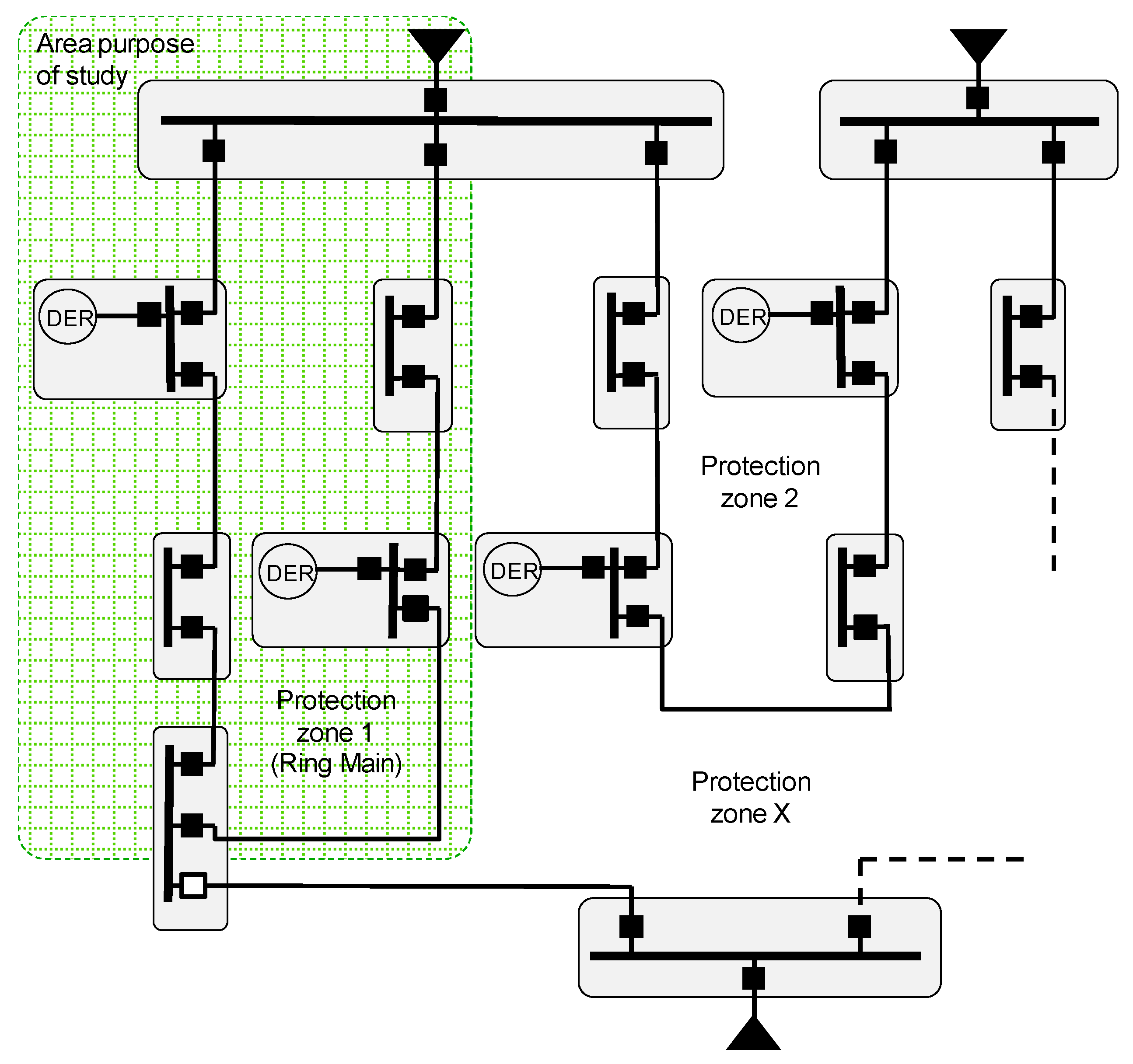
The DER penetration in distribution network can affect mainly to three network aspects: the voltage quality, the current quality and the stability of the system [13]. As mentioned before, one of the objectives of this paper is to find an adaptive network protection for current faults. Therefore, some modification may be necessary regarding the number of DERs that are working in each possible scenario, as shown in Figure 3. According to [14], it will be necessary to introduce a new current setting, a new time setting or even to enable or disable directional protection when a DER is present in the electrical bus. More concretely, the scope of the study in this paper is the protection zone 1 shown in Figure 3.
2.2.1. Ring Main in Closed Operation
The equipment configuration of this topology is based in automatic CBs around the ring. It is an expensive solution but it allows a maximum availability because it avoids a zero voltage drop in the system in case of an electrical fault. When a fault occurs in this topology, every IED activates the pick-up level because the fault current flows from the source to the fault location for both paths. In addition, the two IEDs that are closest to the fault activate the pick-up, but each of them senses the current fault in opposite directions, as it is shown in Figure 4.
In order to implement a priority and to allow the fault isolation only from the closest IEDs to the fault point, it establishes an automatic sequence by ANSI 67/67N protections called logic discrimination. In case of a fault, this sequence sends a temporary block signal (Block Indication) from each IED to their adjacent, in the opposite direction where the fault current comes from. These signals allow a temporary blocking of every IED, except of the closest IEDs (non-blocking ones, because they are not blocked by other), which they are going to trip themselves and to execute a fault fast path isolation in the minimum setting time (typically between 50–100 ms).
It is important to highlight that in Figure 4 there are no indicated voltage transformers for voltage measure but these devices are mandatory in order to the properly function of 67/67N protection as explained before in this section.
In case of CB open failure, considering the blocking signals are temporal, after the logic waiting time (typically 200 ms) the adjacent IED is still sensing the current fault and trips the CB. If the ring is managed in open mode due to system operation, when fault occurs, the current will circulate only for one path from the source to the fault location. In this case, the sequence will be the same way as the one in closed operation, but just on the IEDs that sense the fault current. It is shown in Figure 5.
In the feeders of the busbar in which there is an incomer fed by a source, the selected protections in the feeder (also in the incomer) are ANSI 50/51 and 50N/51N, unlike the rest of the feeder protections of the ring. This option is selected because the ANSI 67/67N will not work properly in this case, when there is a three-phase fault in the busbar and the voltage reference can be lost.
2.2.2. Ring Main Operation with DER Sources
In the case that there are several DERs in the main ring, the fault current level can be significantly different, especially in the islanded mode. This operation mode can affect directly the fault detection because of some sources (distributed generators) will provide current to the fault until their limits, but it can be lower than the fault current in non-islanded mode, when the fault current contribution level reaches the short circuit power of the grid. For this reason, using the same protection setting as the non-islanded mode, the IEDs will not detect the fault and it will not activate any of its over-current protections.
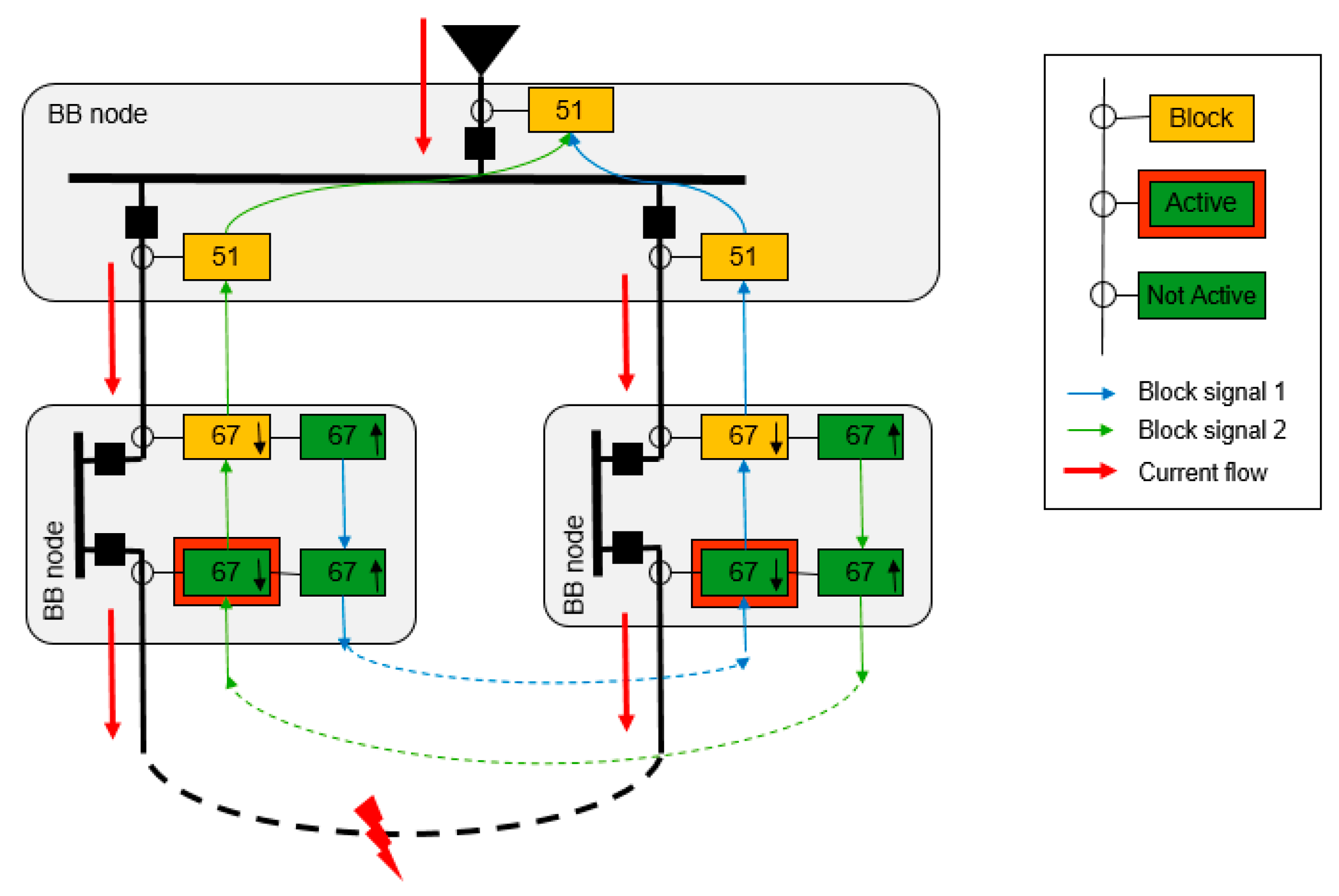
Therefore, in these cases where DERs are present, it is necessary to take in account the islanding mode detection and the currents contribution of DER in the ring faults in order to establish appropriated protection settings. In the migration of the system to an isolated mode, several protections are enabled and others are disabled. As it was comment before, and shown in Figure 6, the ANSI 51/51N protection will be enabled in the IEDs feeders of each busbar where there is a DER, and the ANSI 67/67N protection will be enabled in the rest of IEDs.
Consequently, it will be necessary to know if these DERs are contributing to the fault level, and how it will be this contribution depending on the typology of the DER [15]. Also, the presence of each DER at the time of the fault can establish a different level of contribution in the current fault, and it can be different in each segment of the network.
3. IEC 61850 and Its Usage for Directional Protection
International Electro-technical Commission (IEC) 61850 is a data model and communication architecture standard that allows the interoperation in automation systems in power systems.
The IEC 61850 standard is becoming the most common communication solution in EES of many countries. The standard provides the features and services needed to make this standard the tool for devices’ communication and automation.
The strengths of IEC 61850 are standard modelling object-oriented equipment belonging to the EES and communication services it offers [16]. This communication services offers a dialog both between IED devices, known as the horizontal communication, and between IED devices and the Supervision and Control platforms, known as vertical communication.
3.1. IEC 61850 Data Model
IEC 61850-7-4 part of the standard describes the data model hierarchy. Its target is to virtualize the IED devices in a common object-oriented based model. It defines a hierarchy that is based on a decomposition of the information contained in the devices, through assemblies and subassemblies, to reach the smallest information unit. The set of information that represent the hardware is named Logical Device (LD). The Logical Nodes (LN), which are subsets of LD, represent physical or functional parts of the device. As an example of the LN, the LN MMXU is related with measurement and it contains all the variables measured on the device. Within the LN, there is the Data Object (DO) that includes all data forming the LN. Analogously, the DOs in the LN MMXU are phase-phase voltage (VPP), phase-neutral voltage (PHV), intensity (A), frequency (Hz), etc. Finally, DO ends in the structure of the Data Attributes (DA). DAs in MMXU are, for example, the value of the above magnitudes of DO (V, A or Hz respectively), the quality bit (q) which represents that the value measured is valid or within the defined ranges, and the time stamp (t) which represents the moment in which the measures have been realized.
The standard defines the common structure of LD, LN, DO and DA for all devices in the market, but keeps free the grouping of different LN into groups and subgroups according to functionalities of equipment, such as Measures, Protection, Control, States, etc. Figure 7 shows the virtualization and data model of a medium voltage (MV) cabin and its IED device.
3.2. IEC 61850 Abstracts Models and Communication Services
IEC 61850-8 and 9 standard parts describe the set of communication models and services in order to allow the exchange of the data model information between different IED in electrical power systems. The goal is the deployment of automation of the electrical system by sending data groups of different IED LNs. Figure 8 shows the abstract models and communication services defined in the standard. Finally, they are mapped or encapsulated over an Ethernet network frame.
The first three models are based on a client-server model. The server is the device which contains the information while the client accesses it. Reading and writing models are used to access data and their attributes. The control model is a specialization writing service, which allows management of attributes that are defined in this class, and it allows action on the device. The reporting model is used to exchange a set of event-oriented information, which is transmitted spontaneously when the data value is modified. Today, all these models are mapped over MMS Ethernet protocol in the OSI layer 7.
The other services are based on a publish-subscribe model. In IEC 61850, the term peer-to-peer communication is introduced to emphasize that communication between the publisher and the subscriber involves communication between devices. These communications services are used for the exchange of critical information. The device, which is the source of information, publishes it, and any other equipment that needs this information can receive it by subscribing to it. The GOOSE service is a fast transmission of event information to multiple devices. Instead of using a communication service with receipt confirmation, the information exchanged is repetitively sent for ensuring the arrival to the subscriber. Sample Value (SV) transmission service, is used when is needed to transmit analog field signals, such as current, voltage or any of its derivatives, using digital communications. The analog signals are sampled and transmitted. Both the GOOSE and SV services are encapsulated in OSI layer 2 Ethernet.
On the other hand, the standard allows for an evolution in communications technology, because their models and information exchange services are abstract and uncoupled from the protocols that implement them (MMS, TCP/IP, etc.), which helps to improve communications technology without affecting the standard model and services. An example of this is that the standard is working to provide the mapping of client-server model in Web Services, replacing the MMS.
3.3. GOOSE Service
Conceptually the GOOSE service is implemented to substitute the traditional signal wiring in the control systems, and to add new functionalities. GOOSE provides several advantages over traditional wires:
- traditional wiring is substituted by a medium only for communication,
- a GOOSE can carry more information that a simple cable,
- protection, supervision and control applications use the same physical medium,
- VLAN and QoS implementation capabilities.
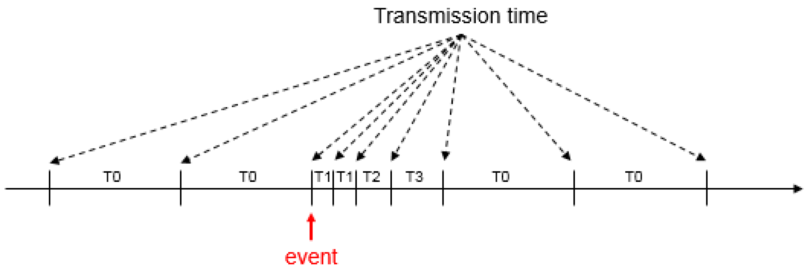
As it was mentioned before, a GOOSE message is based on publish-subscribe pattern. Publishers send GOOSE messages to multicast MAC addresses across the Local Area Network (LAN), and subscribers just listen to what information is in the network and pick the GOOSE messages to which they are subscribed. IEC 61850-8-1 specifies a retransmission scheme to achieve a highly dependable level of message delivery. Figure 9 shows the mechanism of retransmission of GOOSE messages. According to [17], once started, GOOSE messages are published constantly, containing a collection of information called a data set. During configuration, each GOOSE message a max time parameter (T0-seconds) is given between message publications. The messages are published each time one of the data set elements changes or if the max time expires. After a data set element changes, the time of transmission between messages is very short, and a min time parameter (T1-milliseconds) is defined in the GOOSE message. Consequently, the messages are sent very often to increase the likelihood that all subscribers will receive them across the nondeterministic Ethernet. After the initial fast publications, the time of transmission grows longer (T2, T3, Tx) until it reaches max time again.
Also, in GOOSE message a VLAN can be defined, in order to segregate the paths where the GOOSE is transmitted on the LAN, and a priority tag (QoS) can be also specified, to add high priority to the GOOSE message over other frames in the LAN, and avoiding potential delays of this critical message in saturated networks.
The use of IEC 61850 GOOSE service instead of traditional wiring in the ANSI 67/67N protection system offer an optimization of the installation cost, better performance of the system and more options of distributed automation in the ring main topology systems. Several publications [18,19] consider that the usage of GOOSE can reduce considerably the installation costs taking into account that only one Ethernet network is required for the whole system. It increases the possibilities to establish any combination of variables using the same network.
3.4. Related Work on IEC 61850 for Protection Communication and DER Integration
The application of GOOSE service has been verified in publications such as [20,21,22,23], in which this kind of IEC 61850 message is used to make a logic discrimination, transfer application and modify settings between protection relays, IEDs [24,25,26]. GOOSE service has been proposed as an important tool in order to carry out new enhanced automation in electrical network. For example, reference [20] defines a Virtual Power Plant (VPP) model in which IEC 61850 can be used to enhance the interaction with DER, contributing to seamless integration of the DER data to a VPP and facilitating the integration to market applications. Moreover, references [21,22,23] present different studies about how GOOSE enable fast horizontal peer-to-peer communication between several IEDs. For example, reference [21] stated that this technology provides very low latency (4–5 ms) allowing to deploy decentralized functions, such as distributed and autonomous microgrid protection. A fast Fault Location Isolation and Supply Restoration (FLISR) algorithm based on IEC 61850 GOOSE messaging was proposed in [22] to reduce service outage time. However, the algorithm is quite generic it was considered as a starting point for the definition of the algorithm presented in this paper. The advantages of IEC 61850 GOOSE service were also analyzed in [23], highlighting the replacement of complex network of hardwired connection with an Ethernet network for inter-IED communication at the station level.
Furthermore, reference [24] analyzed the usage of IEC 61850 for managing Distribution Automation Systems (DAS) and proposed GOOSE messages as an appropriate technology to transmit time-critical information from one source to multiple receivers. The article also analyzed on the configuration requirements and proposed a configuration solution for a DAS case study. Previous work in [25,26] also studied the advantages of GOOSE messages for operating MV protection at substation, instead of the more complex and expensive hard-wired schemes. However, they do not present a detailed explanation of GOOSE configuration and the required LNs.
Taking into account that the usage of IEC 61850 GOOSE service is a growing trend in recent literature, it was considered that the specific case presented in this paper provides some outputs and conclusions that can be helpful for other researchers of the field in the future. Moreover, the authors identified also an increasing industrial need for the implementation of adaptive protection algorithms, such as the one presented in the following section. Therefore, the solution presented details configuration schemes (including GOOSE messages and IEDs), processes and the control algorithm in order to efficiently manage protection systems in scenarios with DER.
4. Implementation Process
This section shows an example of how to implement the 67–67N protection using IEC 61850 GOOSE service communication. For this purpose, and as an example for facilitating its configuration, the Sepam S82 IED [27] from Schneider Electric (Paris, France) is used, which integrate both protections, and his IEC 61850 integration tool.
However, it must be said that this section focuses on the IEC 61850 integration and does not cover the overall protection configuration. In order to define the parameters of these function protections it will be necessary to develop a discrimination study where the short circuits currents should be analyzed such as in example [28], where several settings are defined according to different scenarios.
CET850 [29] is the IEC 61850 integration tool for Sepam protection relay of Schneider Electric. Figure 10 shows an extract of the data model of Sepam S82 where it is possible to define the IEC 61850 hierarchy and the Time Over Current Protection logical nodes for ANSI 67/67N protections (LN A67_PTOC and LN A67N_PTOC). The number 1 or 2 is referred to the two possible directions of the fault current. The Over Current protection trip condition logical node (LN PTRC1) contains the Block Indication 1 and 2 DO (BlkInd1 and BlkInd2) and its DA in order to implement the blocking signal in the application of the ring protection such how it was introduced above. Also, it is possible to see in the Figure 10 the DO and DA of the protection operation.
The Over Current protection trip condition logical node (LN PTRC1) contains the Block Indication 1 and 2 DO (BlkInd1 and BlkInd2) and its DA in order to implement the blocking signal in the application of the ring protection such how it was introduced above. Also the Figure 10 shows both DO and DA in the IEC 61850 hierarchy.
In order to use the Block Indication information in any IEC 61850 service, it must be included in a DS. In Sepam S82 this DS is implemented and it is called BasicGseDs. The DS and how it is setting in the GOOSE Control Block are showed in Figure 10. Also in the GOOSE Control Block is possible to set the GOOSE ID, and the Min and Max times.
Once the ANSI 67/67N protection is implemented via GOOSE, it will be necessary the implementation of the algorithm that allows the correct protection of the ring main operation in the particular case where there are DERs as sources and the ring is operating in islanded mode as it was introduced before. There are many solutions but the proposal in this paper follows a modular solution and an interoperable solution which allows different vendor devices to be part of this solution.
Regarding these ideas, the solution is focused in the use of the standard IEC 61850 and its ability to create distributed automation as a part of the new adaptive network protection needs. The proposal for the automation is to change the protection settings of the IEDs according the ring operation mode and the number of the DER units connected to the ring at each moment. Therefore, parameters such islanded mode and DERs presence should be known at each bus bar node.
As mentioned previously, the DERs presence in the network will vary the fault level in island mode (also in network connected, but in this case, the variation is insignificant compared to the fault current contribution of the grid). Its means the settings for detection and trip will be modify according it. Also, the DERs presence, change the electrical configuration of the system from the sources point of view, so it will be necessary to change from ANSI 67/67N to ANSI 50/51 and 50N/51N respectively.
Normally the protection settings of ANSI 67N and 51N have to be modified due to there is a change in earth neutral system when the system changes to island mode. The earth neutral system of the main grid can be different to the earth neutral system of the DERs. This change it will be independent of the number of connected DER in the system.
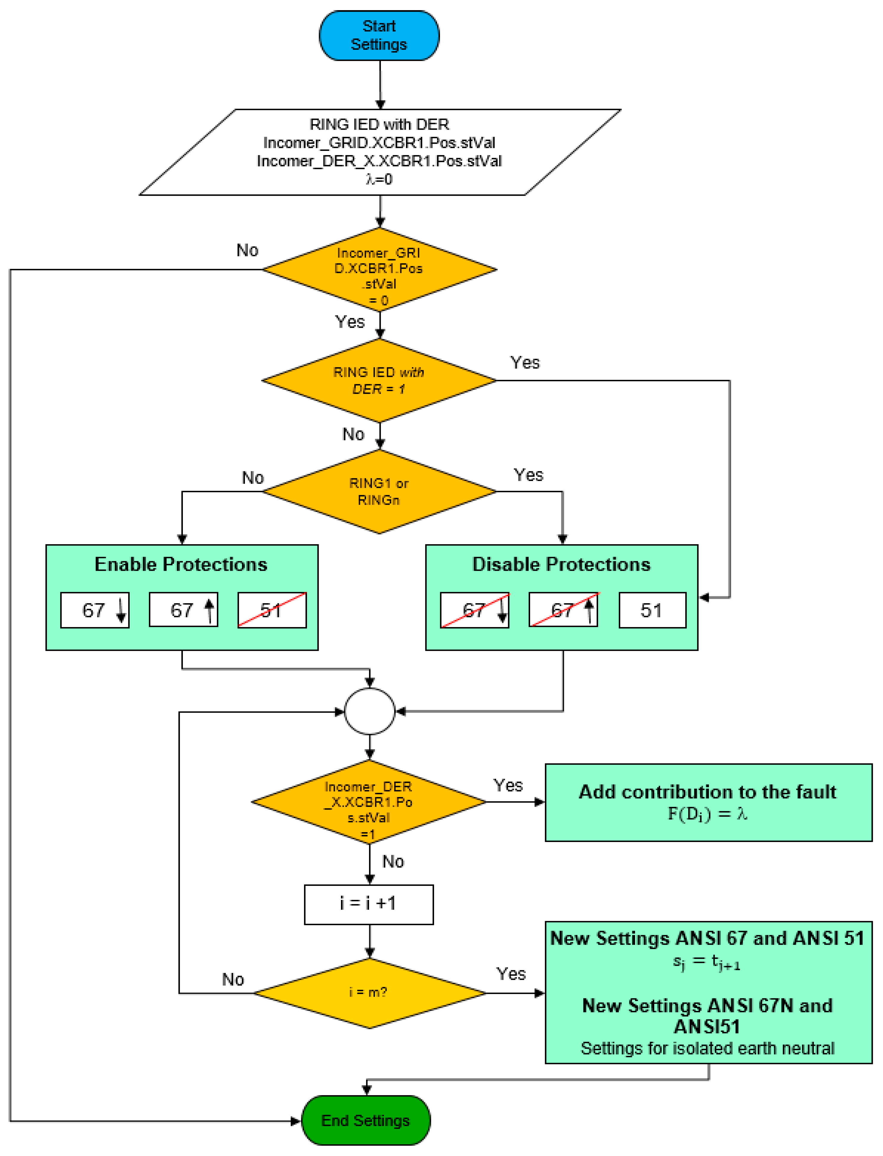
To carry out the adaptive network, the Figure 11 proposes an algorithm to establish this real-time adaptive protection system. It is important to highlight the algorithm have to be implemented only in ring IEDs.
The first part of the algorithm analyzes if the system is in island mode and the type of the ring IED. This ring IED can be a part of a busbar node feed by source or not. After this first treatment, the algorithm decides which protections must be activated.
Once the protection configuration system has been decided it will be necessary to adapt the new protection settings. In order to do this adaptation, each connected DER to the system will contribute in different way to the fault level. So, these possible DER combinations are in following truth table, Table 1, where is a ℕ number which indicates a fault level in the ring and is the value of the DA Incomer_DER_X.XCBR1.Pos.stVal from each incomer DER. In fact, is the result of a function whose variables are the presence of each incomer DER as indicate Equation (1). A low value of will indicate a low contribution fault, for this reason it is be important to sort the truth table according DER combination in the system.
Therefore, every combination has to be simulated to know the fault impact in the system in order to assign the correct value of .
After assigning a contribution level in each combination, the new settings can be selected in each IED. Due to possible limitations settings in each IED for protections ANSI 67 and ANSI 51 protections it will be necessary to establish some levels. The setting level is defined according to Equation (2) where is a parameter which establishes the difference between every level, is the value of setting in [A] and is the number of settings to establish in each ANSI protections. The value obtained before will help to select the appropriate setting for each protection:
To carry out the association of different λ value and number of settings will be necessary to simulate the short-circuit capabilities for every DER combination. It is important to remark that the first protection setting will be in order to avoid a blank setting in the protection in the case that is 0 where the phase fault will be 0 due to there is not generation. In fact, is a blank value.
As mentioned before, there are different IEDs in each bus bar node such as ring, DER and main grid IEDs. The Table 2 shows the data information associated in the DS which will be published through GOOSEs according each IED. It does not only show the information necessary to modify the settings in each ring IED besides, also it shows the GOOSEs and the data for the blocking signal protection system explained before. In the example proposed in this paper, the letter X represents what DER source is connected from in the incomer IED, or the position of the CB in the ring IED (used for the correct logic discrimination protection implementation).
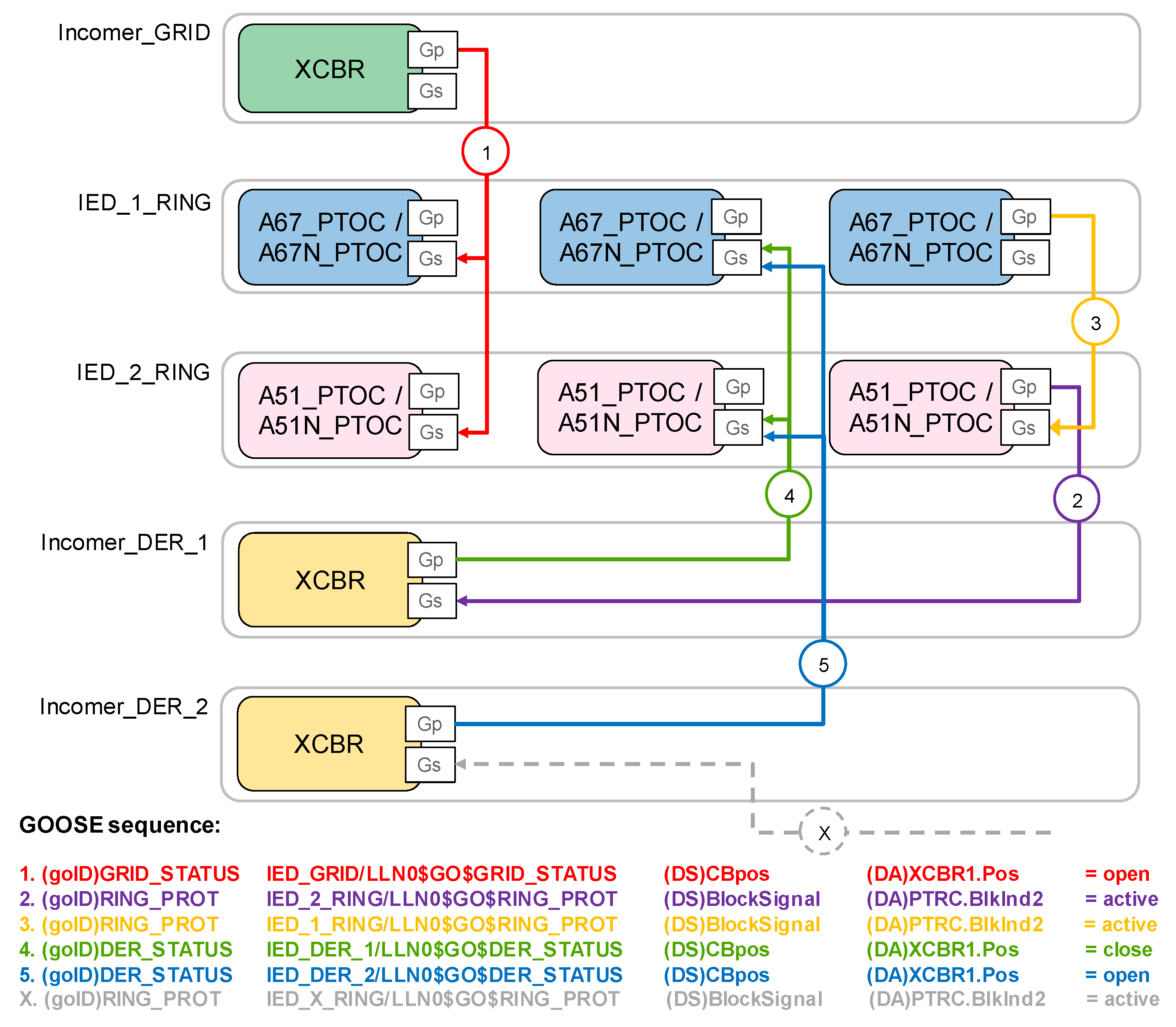
Figure 12 shows a conceptual representation of the GOOSE messages that are published (Gp) by the different IEDs to the communication network and the subscription receivers (Gs) of these GOOSE messages by the other IEDs, in order to implement the automation algorithm.
The ring IEDs will subscribe to GOOSE messages in order to modify settings and besides execute the logic discrimination in the system protection. It is important to remark that the incomer GRID and incomer DER IEDs will only publish to GOOSE messages in island mode.
The GRID_STATUS GOOSE provides information to the other IEDs about the operating mode. On the other hand, DER_STATUS GOOSE provides the information about the presence of the incomer DER_X in the ring. This information will get to the Gs of each ring IED and it will change the protection configuration and settings (S).
Figure 13 shows a part of the GOOSE publication and subscription between several IEDs of the ring. In fact, the incomer IED publishes the status of its circuit breaker through a GOOSE in order to enable or disable the directional protection in ring IEDs 1 and 2. In the other hand, the DER incomers publish a GOOSE message in order to modify the settings of several PTOC protections of ring IEDs mentioned before. Finally, the discrimination system protection is running properly thanks to the GOOSE service that publishes the blocking signal between ring IEDs and the DER incomers.
5. Results
A laboratory mock-up in the Schneider-Electric Spain Headquarters (Barcelona, Spain), shown in Figure 14, emulates real client installations and was used in early states in other to design and validate the directional protection before its implementation in the field. This environment helped to identify the research need and proposed solution in ring main with DER, detecting incorrect fault detection issues in the emulation of real cases (i.e., low fault current levels in the case of islanding operation of the ring main with DER). However, the results presented in this paper are mainly based on simulations for two reasons. First, is that due to privacy issues the data used in the laboratory coming from real scenarios had legal limitations. Second factor is that simulation method used for the paper can be reproduced by other researchers of the field, and allows comparison with future improvements and the obtained results (not exclusively by the authors).
It is necessary to highlight that the adaptive protection system and its automation presented in this paper is developed in the station level of the installation and the communication between IEDs (horizontal communication). It means that the protective system is a decentralized logic (islanded from the design) system, which is independent from superior logical entities or control centers. It works autonomously between the IEDs defined for that target, regardless of the electrical power configuration. When the number of IED participating in the protection system and the algorithm are defined, the different cases of islanding are studied and it is determined the finite number of scenarios taking into account in the implementation of the solution. In addition, it is necessary to add that the target of this paper is to study the microgrids, where the distribution system is based in ring main. The protections and settings used in the test have been extracted from a real critical protection installation. A short-circuit discrimination study has been done for this end-user installation.
Moreover, the protective system is based in an Ethernet communication network. It means that it is necessary to consider, as in every Ethernet implementation in the industrial environment in a critical power system, the redundancy and back-up power supply for all the devices of the system (IEDs, CB motor supply, switches, and others control and protection equipment) to ensure the reliability of the system. Ethernet redundancy protocols are also used such as (RSTP, HSR, PRP, etc.) in order to avoid the failures in the communication network. Thus, to fully understand the application of the ANSI 67/67N using GOOSE service several tests were realized and results are shown as follows. Figure 15 shows a simulation of a phase fault in the phase 2 of a power system. The tested Sepam senses the fault current direction to line and it sends to the opposite direction the blocking indication 1 (BlkInd1) to block the action of adjacent IED. After the setting time, the CB associate in order to isolate the fault relays opened. By means of an Ethernet conventional network analyzer software, it was captured that the blocking indication 1 (BlkInd1) is activated and it triggers a set of GOOSE.
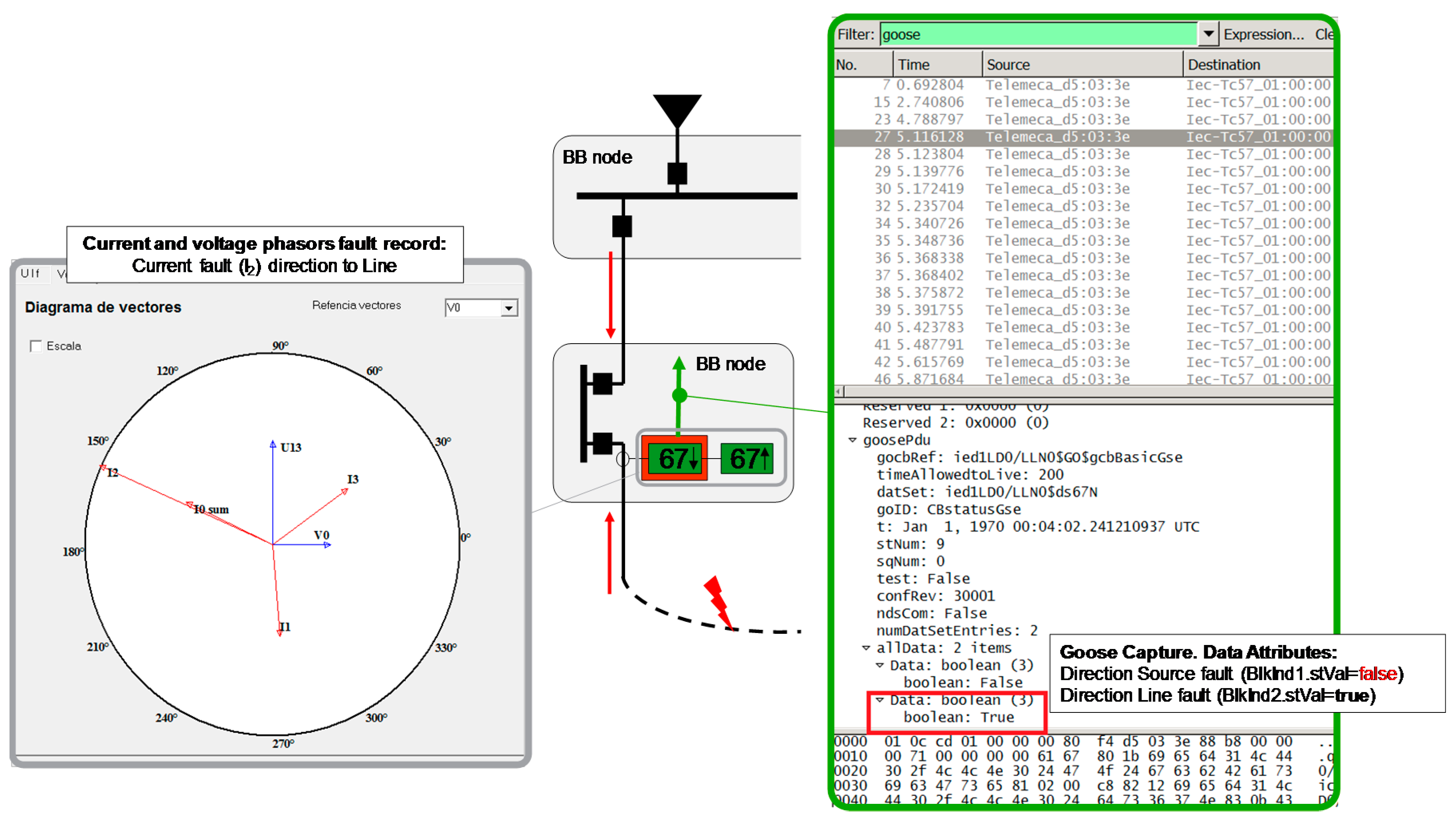
Figure 16 shows the same phase fault but in this case the tested Sepam senses the fault’s current direction to source. Now, it sends to the opposite direction a blocking indication 2 (BlkInd2) to block the action of the adjacent IED.
Also, after the setting time, Sepam opened the CB fault. This time, the Ethernet network analyzer capture shows that it is activated the blocking indication 2 (BlkInd2) and it triggers another set of GOOSEs, while the blocking indication 1 keeps false.
In addition, it was checked that both block indications return to the inactive state after blocking time of its activation. It allows that in case the CB down is not operating, the next one is ready to trip after this time. Figure 17 shows the sequence in the case of CB (CB2) open failure and the action of the adjacent CB (CB1), according IED algorithm in [30].
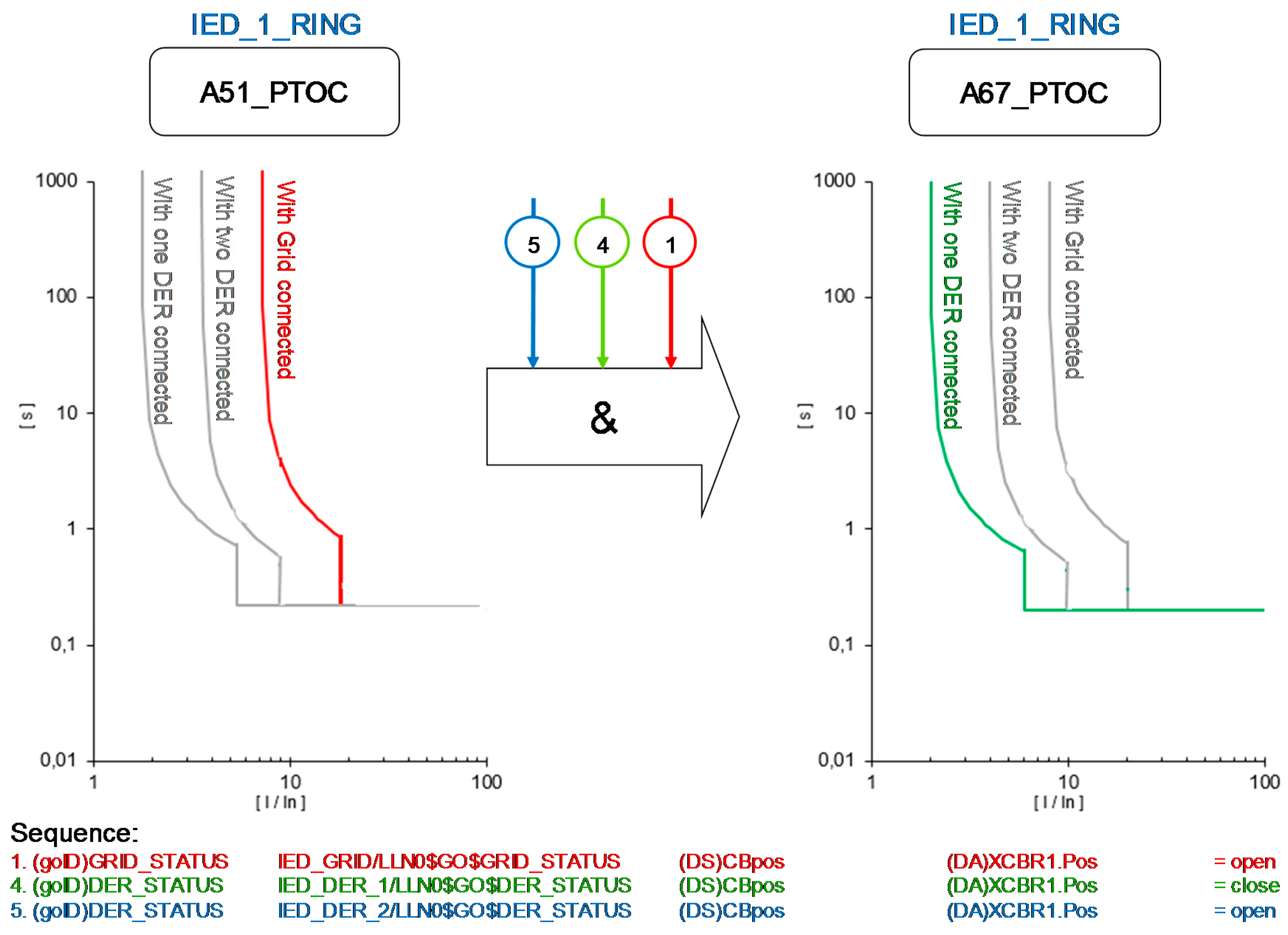
The algorithm provides changes in settings protection and even the kind of protection in order to adapt the IEDs to each new scenario. As shown in Figure 18, the IED_1_RING changes the kind of protection and the settings after receiving the change of the GOOSE services from Incomer GRID and incomer DERs 1 and 2.
In this example, the status of the circuit breaker of the Incomer Grid is opened and then the network is on islanding mode, being the DER 1 connected to the network and DER 2 is disconnected. Therefore, this status provides a change in overcurrent level ANSI 51 from 400A to 100A and in short circuit level ANSI 50 from 1000A to 300A. It is necessary to remark that the kind of protection has also changed from directional protection ANSI 67. Obviously other kind of protections have been implemented, such as voltage protection ANSI 27 or frequency protection ANSI 81, but it has not been linked with this algorithm. The values have been extracted from real end user installation where the algorithm has been implemented although for reasons of confidentiality is not possible to mention the name of this installation.
The application of GOOSE service provides several benefits to the electrical system not only for the protection system but also at the global level of the project. Therefore, some of the benefits of logic discrimination using IEC 61850 GOOSE service are highlighted in Table 3.
Table 3 compares the difference between both discrimination systems and defines approximately obtained benefits through field experience of the authors and analysed references on this document. As mentioned before, the process explained before has been implemented in a real end user installation where more than 80 IEDs are connected in an Ethernet communication network using the standard IEC 61850. Specifically, 20 of these IEDs are using the GOOSE service in order to establish the exposed protection system before.
After to use this kind of system in several projects it is important to remark that the savings has been approximately in 90% because the dedicated signal between IED has been replaced by GOOSE configuration in IEDs. Additionally, it is possible to find an installation cost reduction about 30%. Although the total cost reduction is emphasized when there is a distance between bus bar nodes more than 100–150 m and they are not in the same room.
The emission times of GOOSE messages are in the range of 2 ms to 4 ms. Even the Ethernet network is non-deterministic, using nowadays redundancy network protocols as HSR and PRP with 0 s [31] of recovering time, the transmission time of the GOOSE in the networks is taken as deterministic over the configuration time. Nevertheless, a digital contact in a IED has a contact time about 4 ms and if there is a long distance, as mentioned before, it will be necessary to use other kind of conversion hardware to send the binary signal between relays, and then the time will increase considerably over 20 ms. For this reason, the latching signals which have been exposed before will have a reduced time, about 70%, in comparison with traditional wiring.
In general terms, the use of IEC 61850 in this kind of installations can help in system cost reduction during the engineering process of the project as mentioned in [32] or during the maintenance of the ownership in [33]. The configuration tools contribute considerably in these processes reducing the time and obviously due to the different vendors’ devices provide the same objects hierarchy description. However, all these advantages require basic communication knowledge from engineers, integrators and maintenance workers, versus the easier wired systems.
6. Conclusions
This paper presents the detection basics of ANSI 67/67N protection and its use in a ring main system based on automatic circuit breakers. It is combined with the implementation of GOOSE service in ANSI 67/67N and adaptive protection solution was designed, detailing its configuration settings and testing and validating its deployment in different cases.
For this purpose, laboratory tests and real installations emulation were deployed. In those tests all the system design and configuration details were specified in order to help to understand how IEC 61850 GOOSE service can be configured to simplify the integration with electric protection systems and provide more flexible and adaptive solutions. Moreover, a control algorithm is defined showing how to set the Blocking Indication DAs triggers in GOOSEs in order to implement the directional blocking signals in the IEDs of the system. In summary, the obtained results in the simulation of the proposed solution show the benefits of using IEC 61850 instead of the hard-wired network connections in terms of the cost of the infrastructure, outage time reduction and the system flexibility, and the paper validates and evaluates a use case example of the IEC 61850 GOOSE service for facilitating an adaptive 67/67N protection configuration.
In addition to this, although the use case is specific for this scenario, this research continues the study and analysis of the data transmission possibilities for building up novel communication paradigms and architectures in the Smart Grid, and can guide the implementation and deployment of several SDU applications for the automation in microgrids and smart grids at distribution level.
In future work, the authors plan to study the usage of this type of applications in Wide Area Network (WAN) instead of LAN using R-GOOSE and R-SV for Wide Area Monitoring Protection and Control (WAMPAC) systems.
Acknowledgments
The authors would like to thank Schneider Electric for the use of its laboratory in Spain Headquarters.
Author Contributions
Ángel Silos developed the algorithm described in this article and Aleix Señís led the design and execution of the implemented tests. Ángel Silos, Aleix Señis and Ramon Martín de Pozuelo specified the usage and configuration of the IEC 61850 in the presented use case, analysed the obtained results and contributed in the writing of the entire paper. Agustín Zaballos participated in the conceptualization of the article, supervised the analysis of the results and provided his extensive scientific knowledge in the writing and reviewing of the entire paper.
Conflicts of Interest
The authors declare no conflict of interest.
References
- Gholizadeh, N.; D’Antona, G.; Della Giustina, D. IEC 61850 Standard and Its Capabilities in Protection Systems. Master’s Thesis, Politecnico di Milano, Milan, Italy, 2016. [Google Scholar]
- Della Giustina, D.; Dedè, A.; Alvarez, A.; Ramos, F. Toward an adaptive protection system for the distribution grid by using the IEC 61850. In Proceedings of the IEEE International conference on Industrial Technology (ICIT), Seville, Spain, 17–19 March 2015. [Google Scholar]
- Eriksson, M.; Armendariz, M.; Vasilenko, O.; Saleem, A.; Nordström, L. Multiagent-based distribution automation solution for self-healing grids. IEEE Trans. Ind. Electron. 2015, 62, 2620–2628. [Google Scholar] [CrossRef]
- Gaouda, A.M.; Abdrabou, A.; Shaban, K.; Khairalla, M.; Abdrabou, A.M.; El Shatshat, R.; Salama, M.M.A. A Smart IEC 61850 Merging Unit for Impending Fault Detection in Transformers. IEEE Trans. Smart Grid 2016, PP, 1–10. [Google Scholar] [CrossRef]
- Lauria, S.; Codino, A.; Calone, R. Protection system studies for ENEL Distribuzione’s MV loop lines. In Proceedings of the 2015 IEEE Eindhoven PowerTech, Eindhoven, The Netherlands, 29 June–2 July 2015. [Google Scholar]
- Martin de Pozuelo, R.; Zaballos, A.; Navarro, J.; Corral, G. Prototyping a Software Defined Utility. Energies 2017, 10, 818. [Google Scholar] [CrossRef]
- Selga, J.M.; Corral, G.; Zaballos, A.; Martín de Pozuelo, R. Smart grid ICT research lines out of the European project INTEGRIS. Netw. Protoc. Algorithms 2014, 6, 93–122. [Google Scholar] [CrossRef]
- Short, M.; Abugchem, F.; Dawood, M. Tunnelling Horizontal IEC 61850 Traffic through Audio Video Bridging Streams for Flexible Microgrid Control and Protection. Energies 2016, 9, 204. [Google Scholar] [CrossRef]
- Altuve Ferrer, H.J.; Schweitzer, O.E. Modern Solutions for Protection, Control and Monitoring of Electric Power Systems; Schweitzer Engineering Laboratories, Inc.: Pullman, WA, USA, 2010; ISBN 0972502637. [Google Scholar]
- Bertrand, P. Cahier technique n° 181. In Directional Protection Equipment; Schneider-Electric: Grenoble, France, 1996. [Google Scholar]
- Gönen, T. Electric Power Distribution System Engineering; McGraw-Hill: New York, NY, USA, 1986; ISBN 0-07-023707-7. [Google Scholar]
- IEEE. Std C37.2™-2008. IEEE Standard for Electrical Power System Device Function Numbers, Acronyms, and Contact Designations, IEEE: New York, NY, USA, 2008. [Google Scholar]
- Bollen, M.; Häger, M. Power Quality: Interactions between Distributed Energy Resources, the Grid and Other Costumers; Stri AB: Ludvika, Sweden, 2005. [Google Scholar]
- Deuse, J.; Grenard, S.; Bollen, M.; Häger, M.; Sollerkvist, F. Effective Impact of DER on Distribution Network Protection. In Proceedings of the CIRED 19th International Conference on Electricity Distribution, Vienna, Austria, 21–24 May 2007. [Google Scholar]
- DTI. The Contribution to Distribution Network Fault Levels from the Connection of Distributed Generation; DTI. URN 05/636; The National Archives: Kew, UK, 2010.
- Berry, T.; Guise, L. IEC 61850 for Distribution Feeder Automation. In Proceedings of the IET International Conference on Resilience of Transmission and Distribution Networks (RTDN), Birmingham, UK, 22–24 September 2015. [Google Scholar]
- Hou, D.; Dolezilek, D. IEC 61850. What It Can and Cannot Offer to Traditional Protection Schemes. SEL J. Reliab. Power 2010, 1, 1–11. [Google Scholar]
- Tibbals, T.; Dolezilek, D. Case Study: New Testing and Verification Practices for Virtual Wiring Among IEDs Via Ethernet Communications. In Proceedings of the Southern African Power System Protection Conference, Johannesburg, South Africa, 10–12 November 2010. [Google Scholar]
- Doleziek, D.; Whitehead, D.; Skendzic, V. Integration of IEC 61850 GSE and Sampled Value Services to Reduce Substation Wiring. In Proceedings of the 47th Annual Minnesota Power Systems Conference Brooklyn Center, Minnesota, MN, USA, 1–3 November 2011. [Google Scholar]
- Etherden, N.; Vyatkin, V.; Bollen, M.H. Virtual power plant for grid services using IEC 61850. IEEE Trans. Ind. Inform. 2016, 12, 437–447. [Google Scholar] [CrossRef]
- Cintuglu, M.H.; Ma, T.; Mohammed, O.A. Protection of autonomous microgrids using agent-based distributed communication. IEEE Trans. Power Deliv. 2017, 32, 351–360. [Google Scholar] [CrossRef]
- Parikh, P.; Voloh, I.; Mahony, M. Fault location, isolation, and service restoration (FLISR) technique using IEC 61850 GOOSE. In Proceedings of the 2013 IEEE Power and Energy Society General Meeting (PES), Vancouver, BC, Canada, 21–25 July 2013; pp. 1–6. [Google Scholar]
- Ali, I.; Thomas, M.S.; Gupta, S. Methodology & tools for performance evaluation of IEC 61850 GOOSE based protection schemes. In Proceedings of the 2012 IEEE Fifth Power India Conference, Murthal, India, 19–22 December 2012; pp. 1–6. [Google Scholar]
- Zhu, Z.; Xu, B.; Brunner, C.; Yip, T.; Chen, Y. IEC 61850 Configuration Solution to Distributed Intelligence in Distribution Grid Automation. Energies 2017, 10, 528. [Google Scholar] [CrossRef]
- Man, T.K.; Ng, P.Y. Goose interlock overcurrent protection for 11KV double-busbar substation. In Proceedings of the 10th International Conference on Advances in Power System Control, Operation & Management (APSCOM 2015), Hong Kong, China, 8–12 November 2015. [Google Scholar]
- Cabrera, C.; Chiu, S.; Nair, N.K.C. Implementation of arc-flash protection using IEC 61850 GOOSE messaging. In Proceedings of the 2012 IEEE International Conference on Power System Technology (POWERCON), Auckland, New Zealand, 30 October–2 November 2012; pp. 1–6. [Google Scholar]
- Schneider Electric. Sepam Series 80. Protection, Metering and Control Functions; Schneider-Electric: Grenoble, France, 2017. [Google Scholar]
- Ates, Y.; Rifat Boynuegri, A.; Uzunoglu, M.; Nadar, A.; Yumurtaci, R.; Erdinc, O.; Paterakis, N.; Catalão, J. Adaptive Protection Schme for a Distribution System Considering Grid-Connected and Islanded Modes of Operation. Energies 2016, 9, 378. [Google Scholar] [CrossRef]
- Schneider Electric. Sepam IEC 61850 Communication; Schneider-Electric: Grenoble, France, 2013. [Google Scholar]
- Silos, A. Inteligencia Distribuida en la Red Eléctricas: Solución Self-Healing. Energética, XXI. Available online: www.energetica21.com (accessed on 9 May 2013).
- IEC. 62439-3. Industrial Communication Networks. High Availability Automation Networks. Part 3: Parallel Redundancy Protocol (PRP) and High-Availability Seamless Redundancy (HSR); IEC: Geneva, Switzerland, 2016. [Google Scholar]
- Gauci, A. Effect on Substation Engineering Costs of IEC 61850 and System Configuration Tools; Schneider-Electric: Grenoble, France, 2013. [Google Scholar]
- Hossenlop, L. Engineering Perspectives on IEC 61850. IEEE Power Energy Mag. 2007, 5, 45–50. [Google Scholar] [CrossRef]
Figure 1.
Earth fault detection and waveforms example.
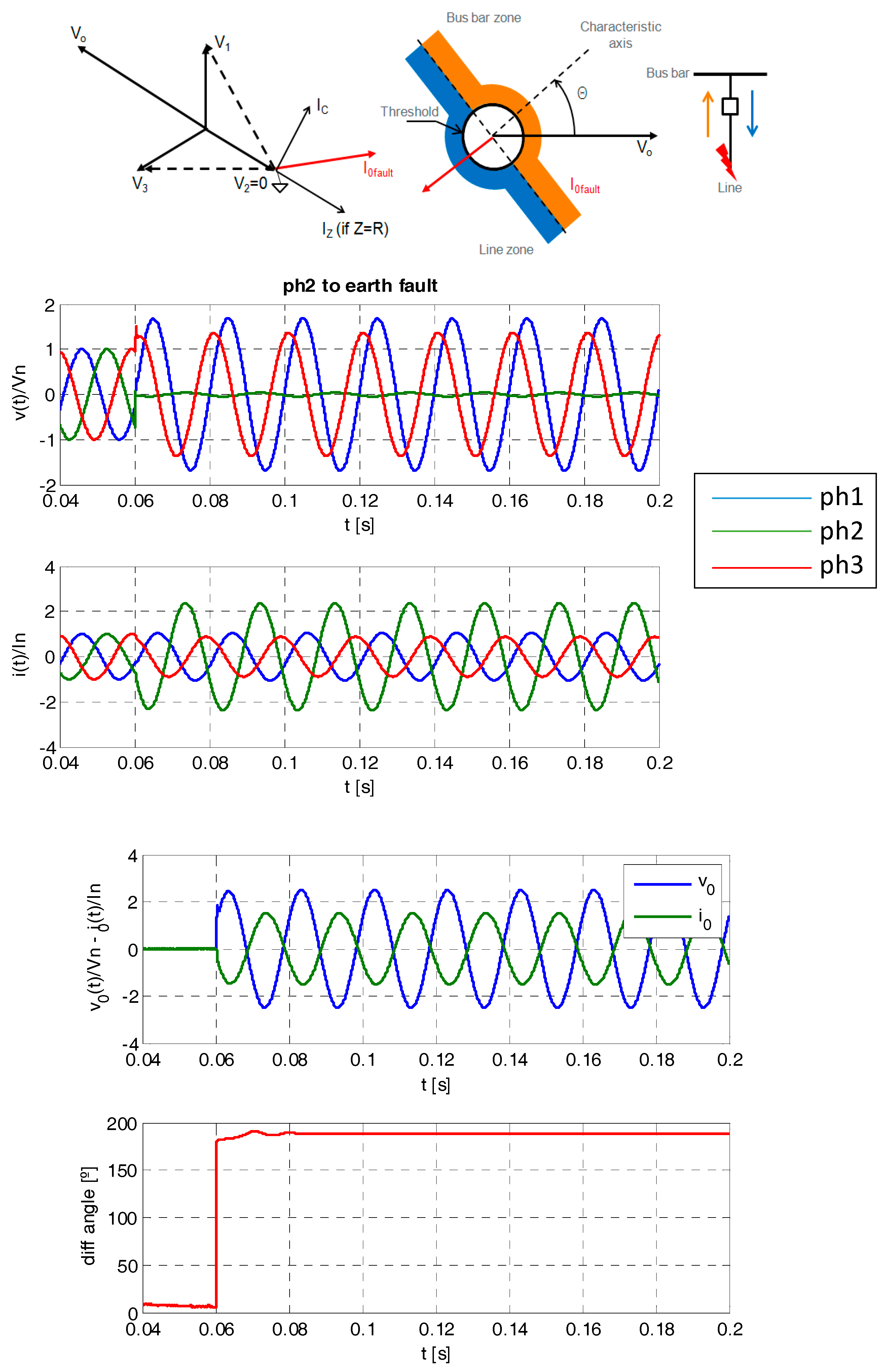
Figure 2.
Phase fault detection and waveforms.
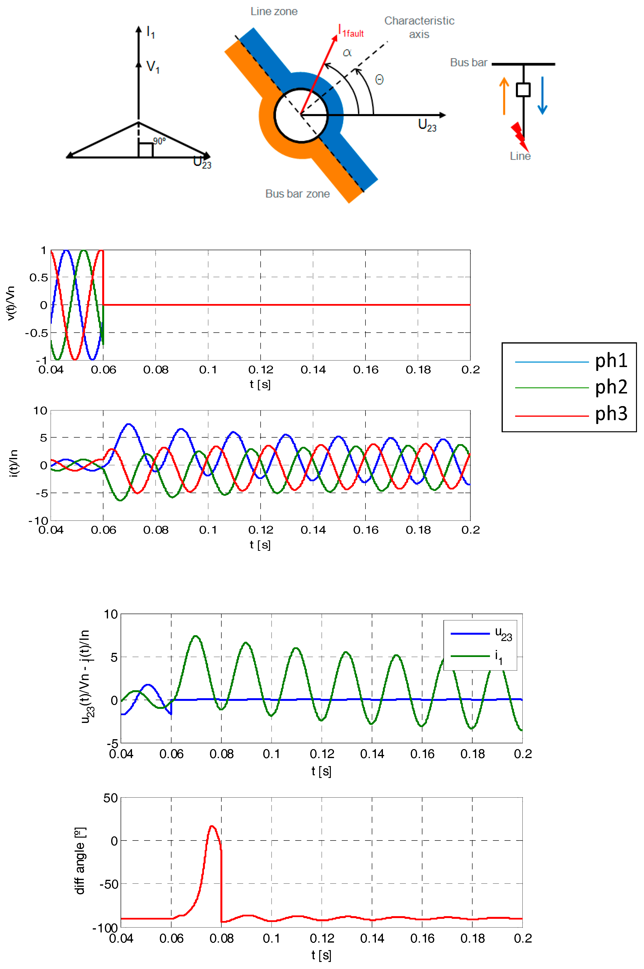
Figure 3.
Electrical distribution network with DER presence.

Figure 4.
Ring main system based in automatic circuit breakers.

Figure 5.
Electrical ring main system based in automatic circuit breakers in open mode.
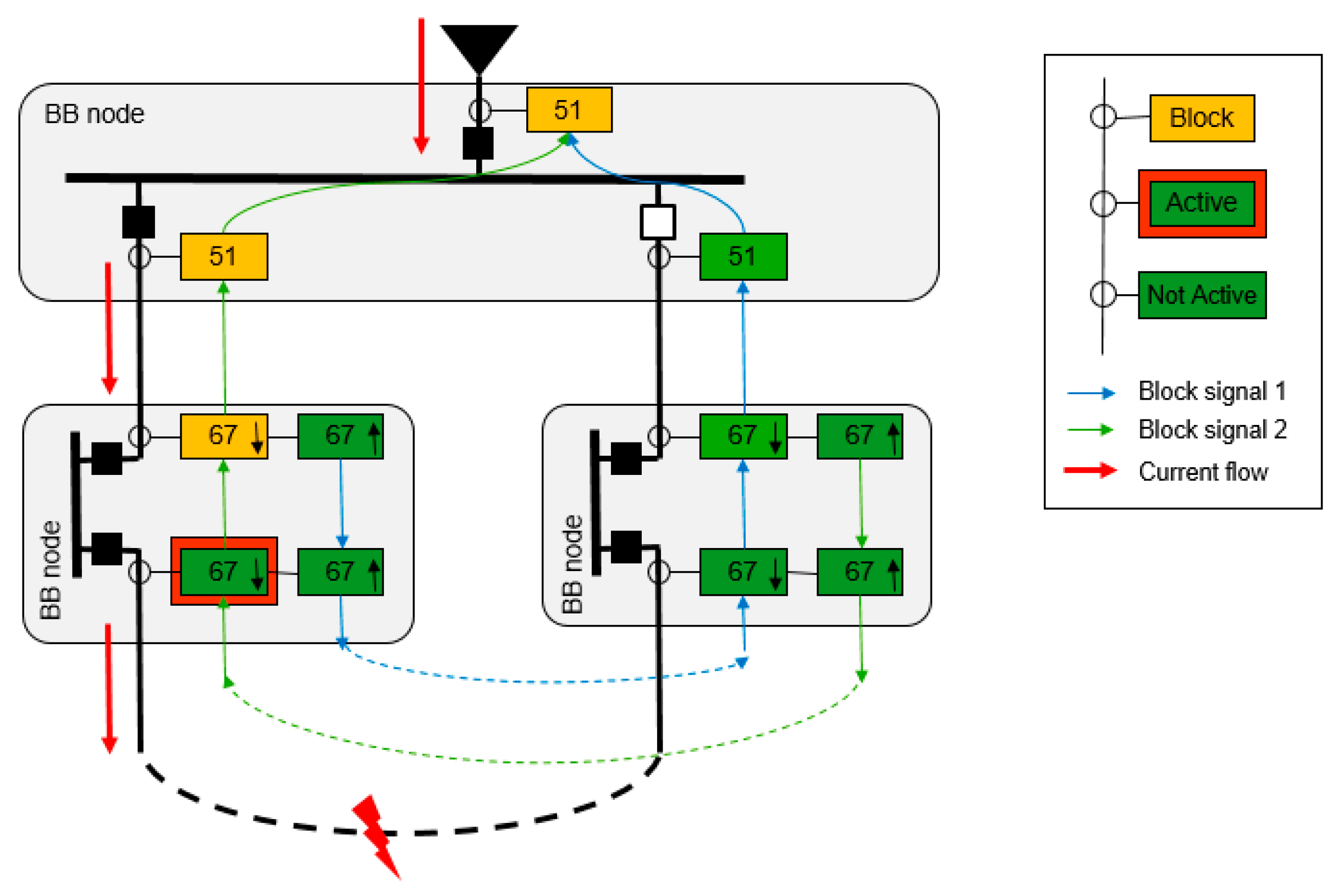
Figure 6.
Electrical ring main system with DER in islanded mode.
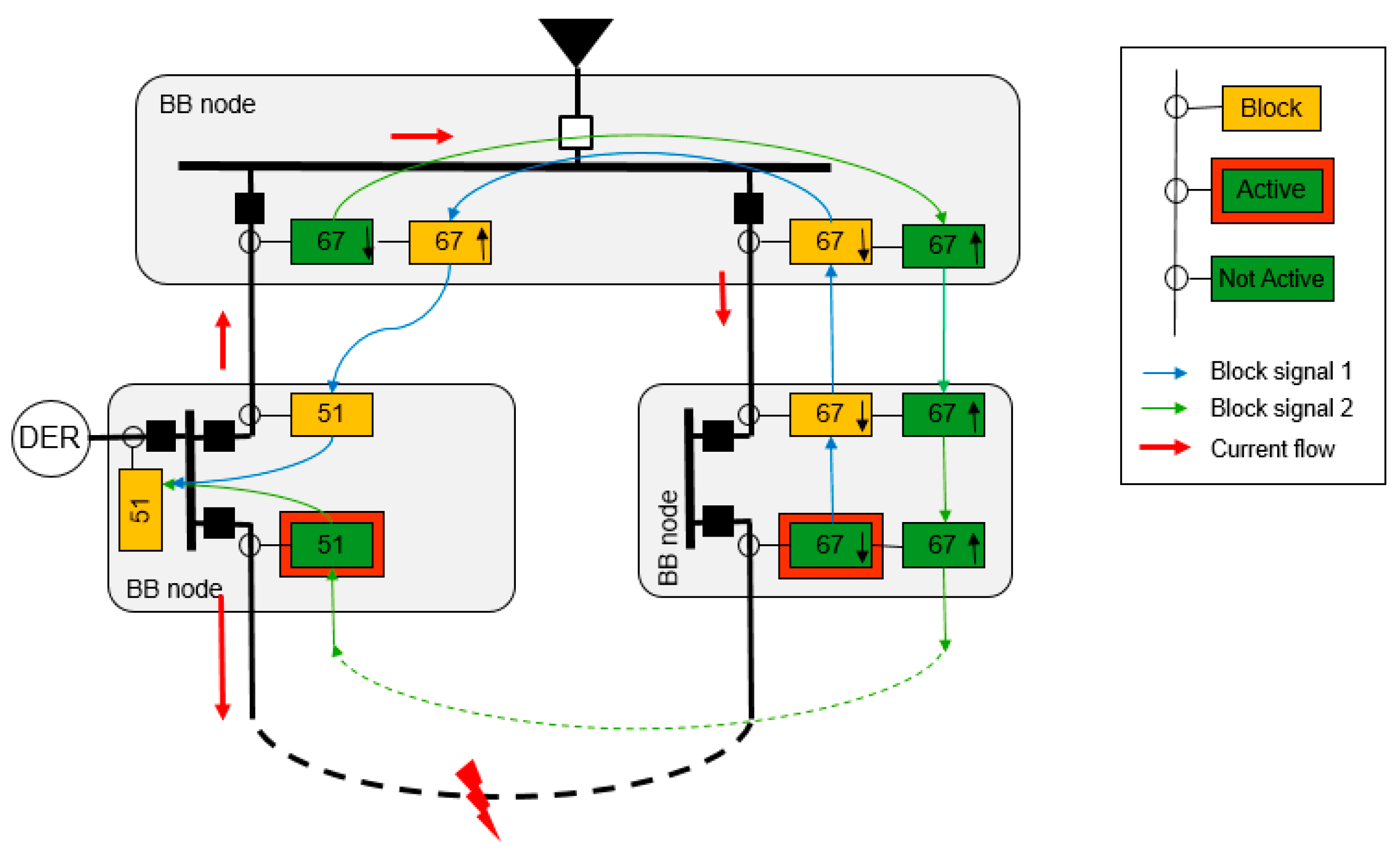
Figure 7.
Data model of MV cubicle and its protection relay.
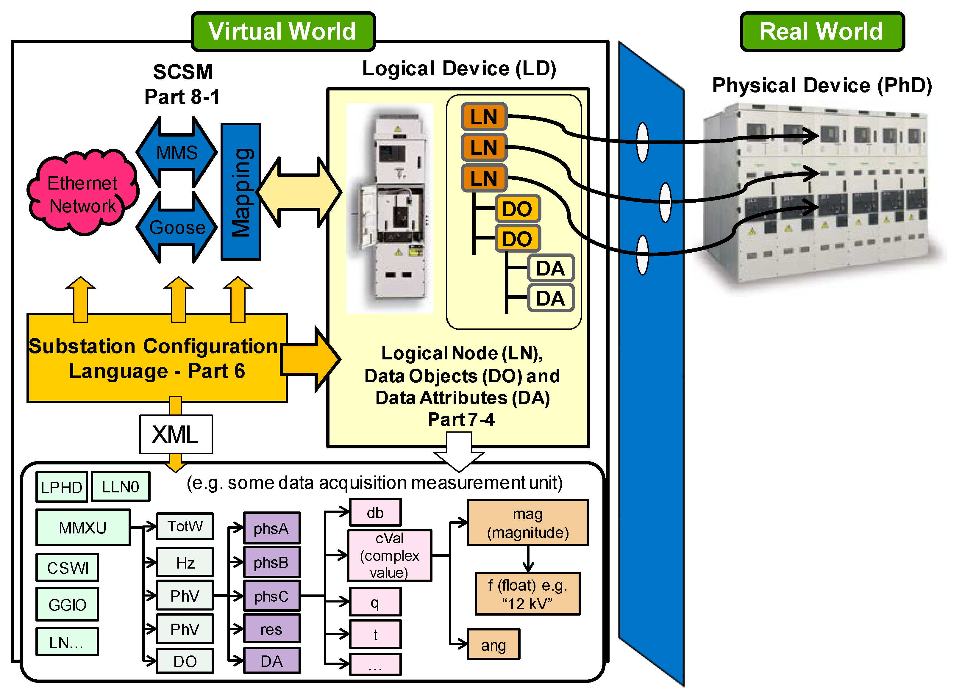
Figure 8.
Abstracts models and communication and services.
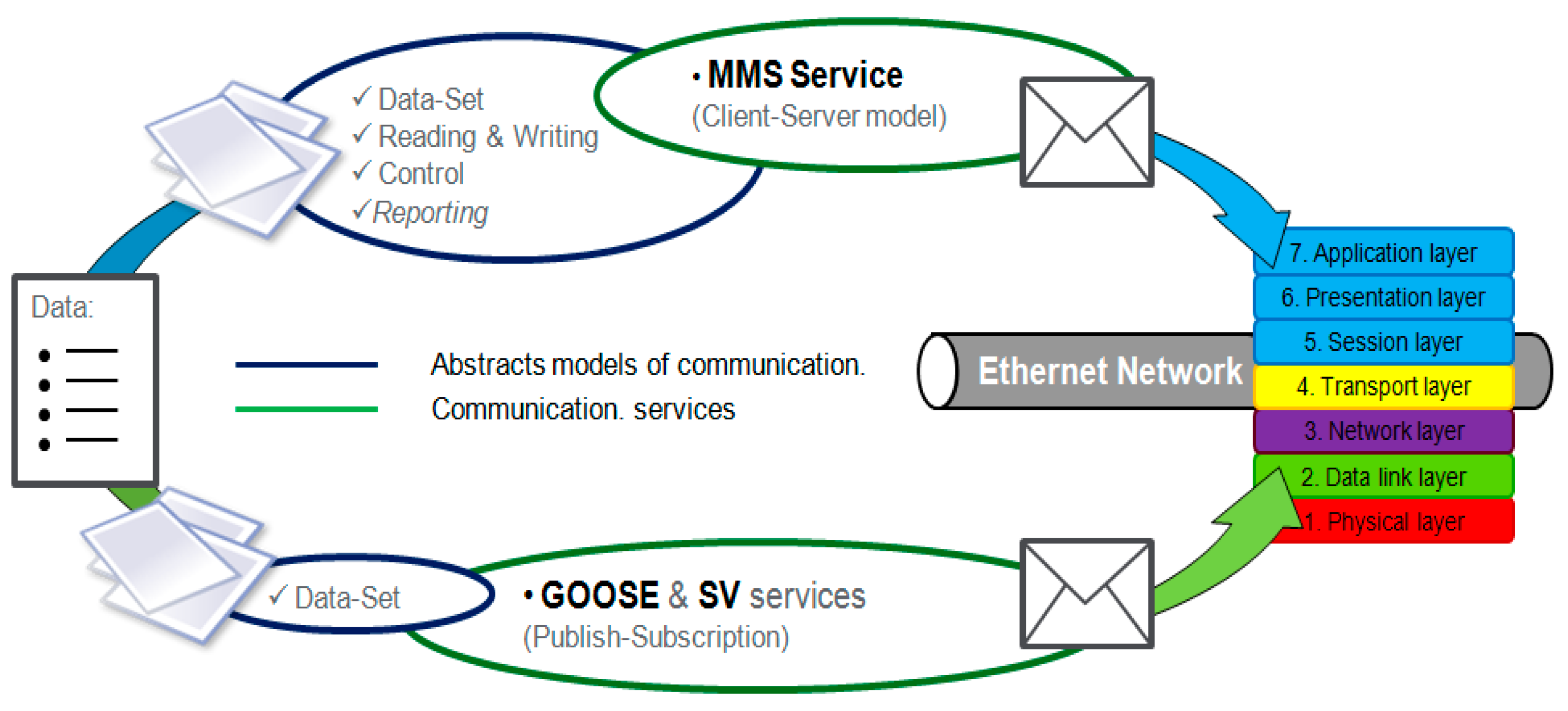
Figure 9.
Example of changing time between message publications.

Figure 10.
Sepam S82 implementation data model.
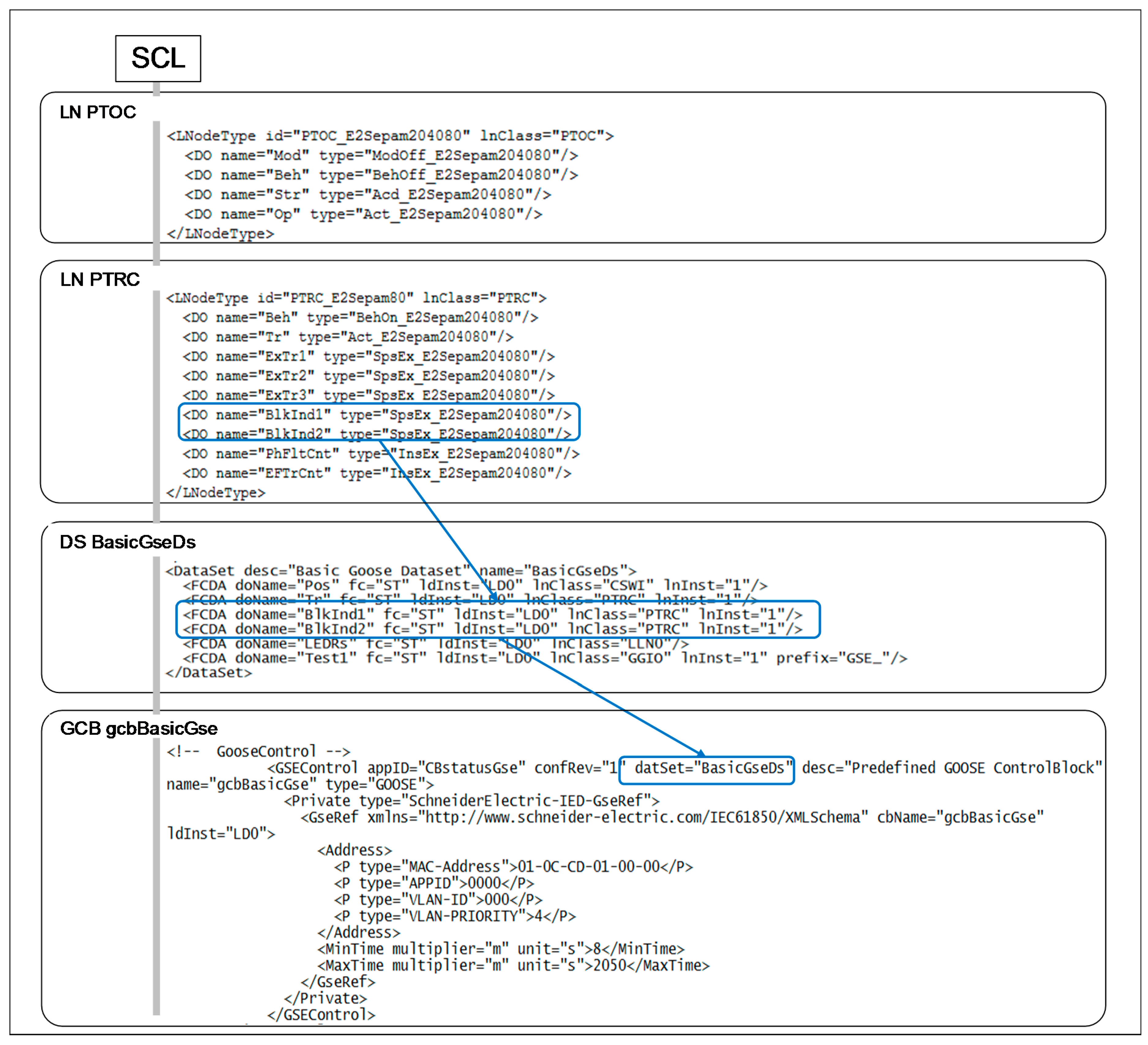
Figure 11.
DS (up) and GOOSE Control Block (down) implementation.

Figure 12.
GOOSE flow in the communication network.
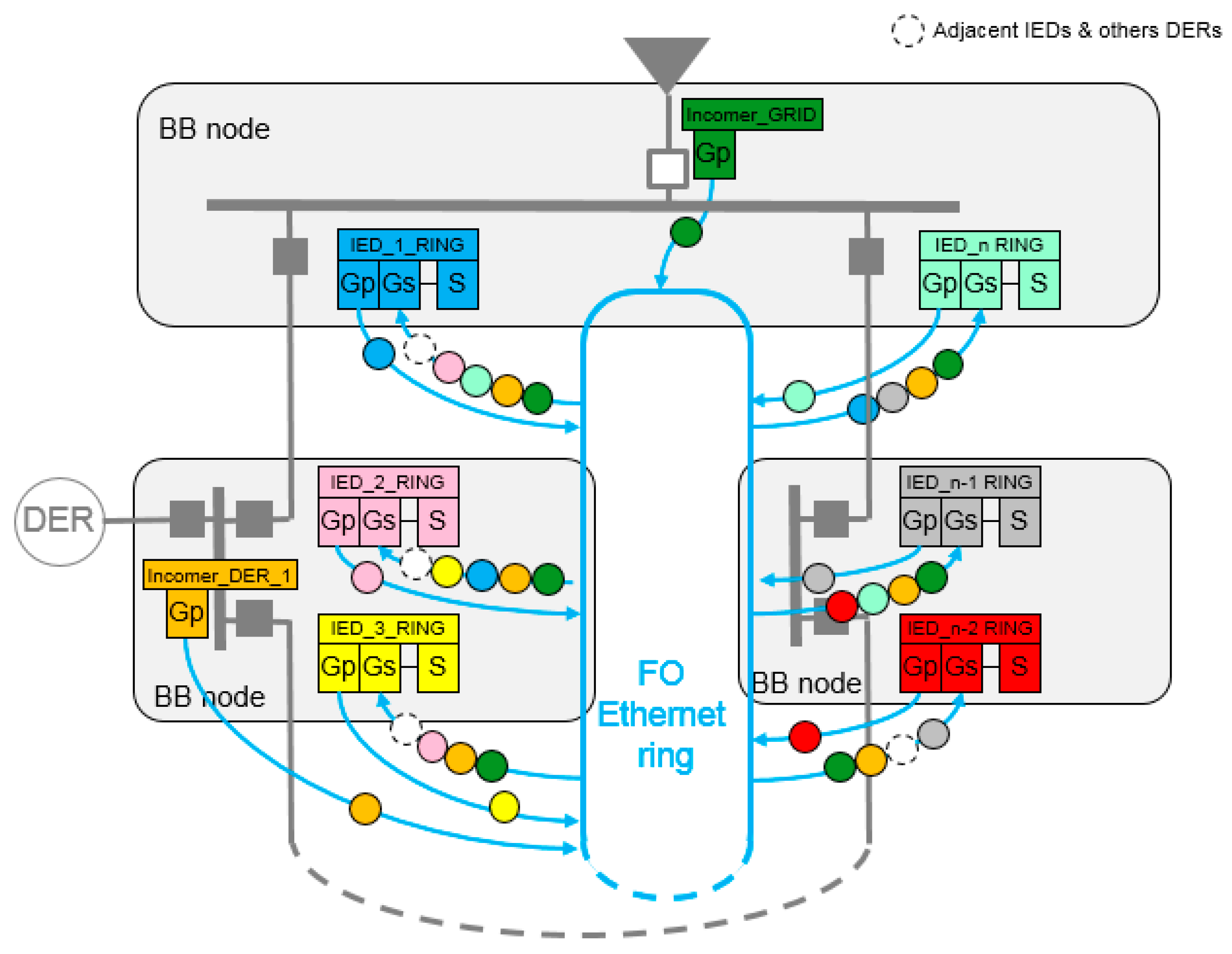
Figure 13.
GOOSE publication and subscription between several IEDs.

Figure 14.
Laboratory mock-up.
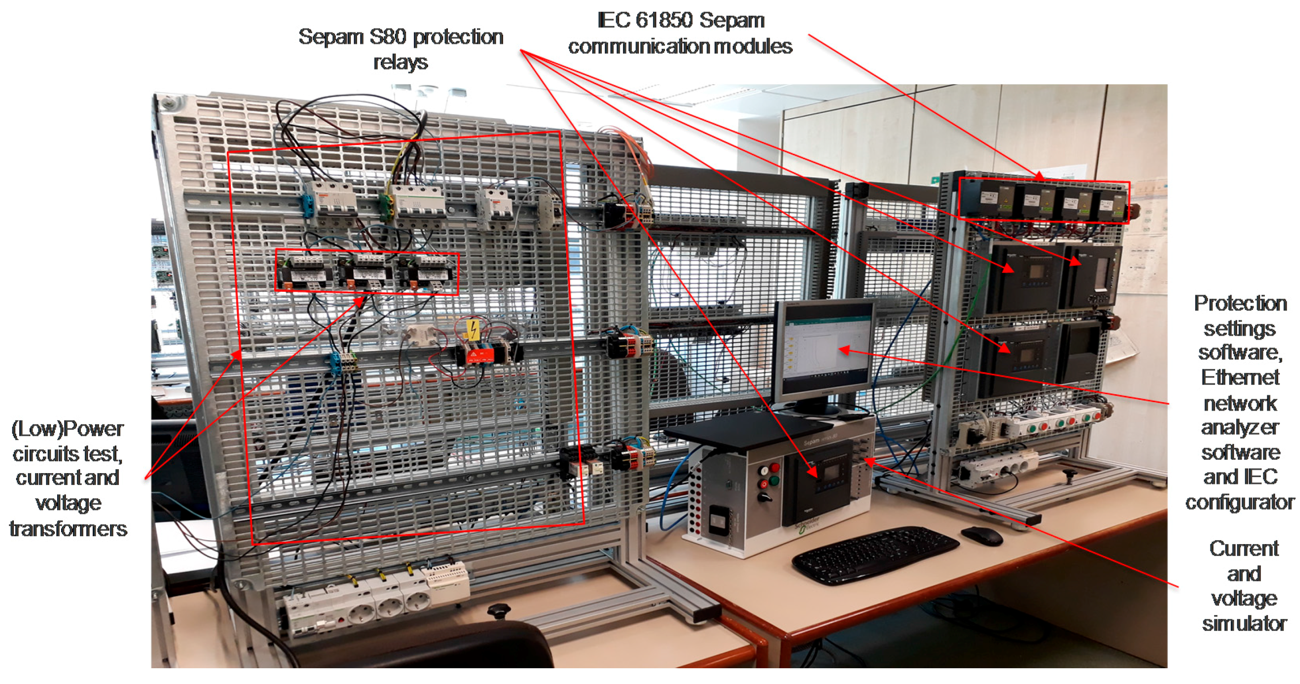
Figure 15.
Line direction phase-2 fault.
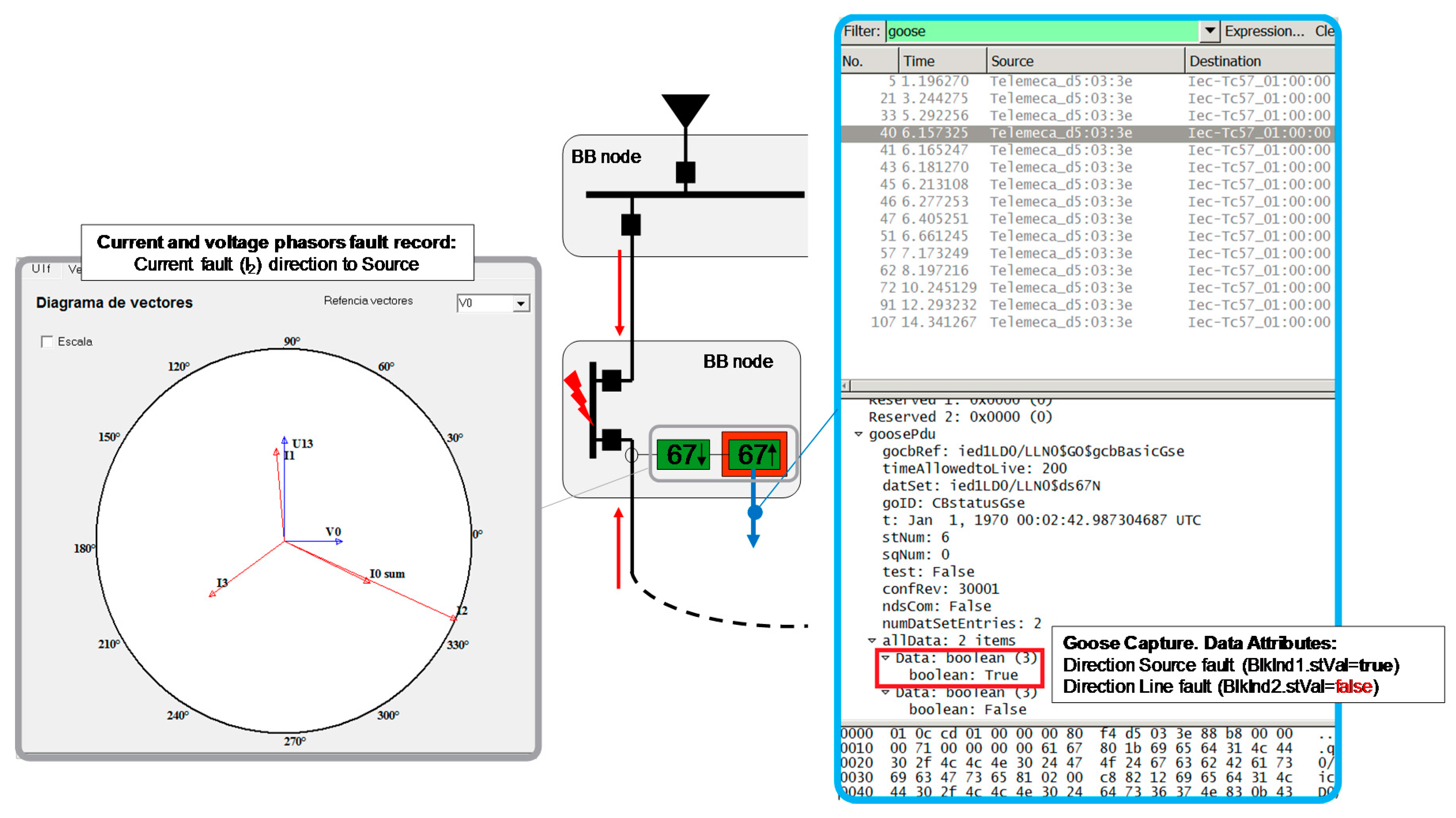
Figure 16.
Source direction phase-2 fault.

Figure 17.
CB failure in ring main distribution system.
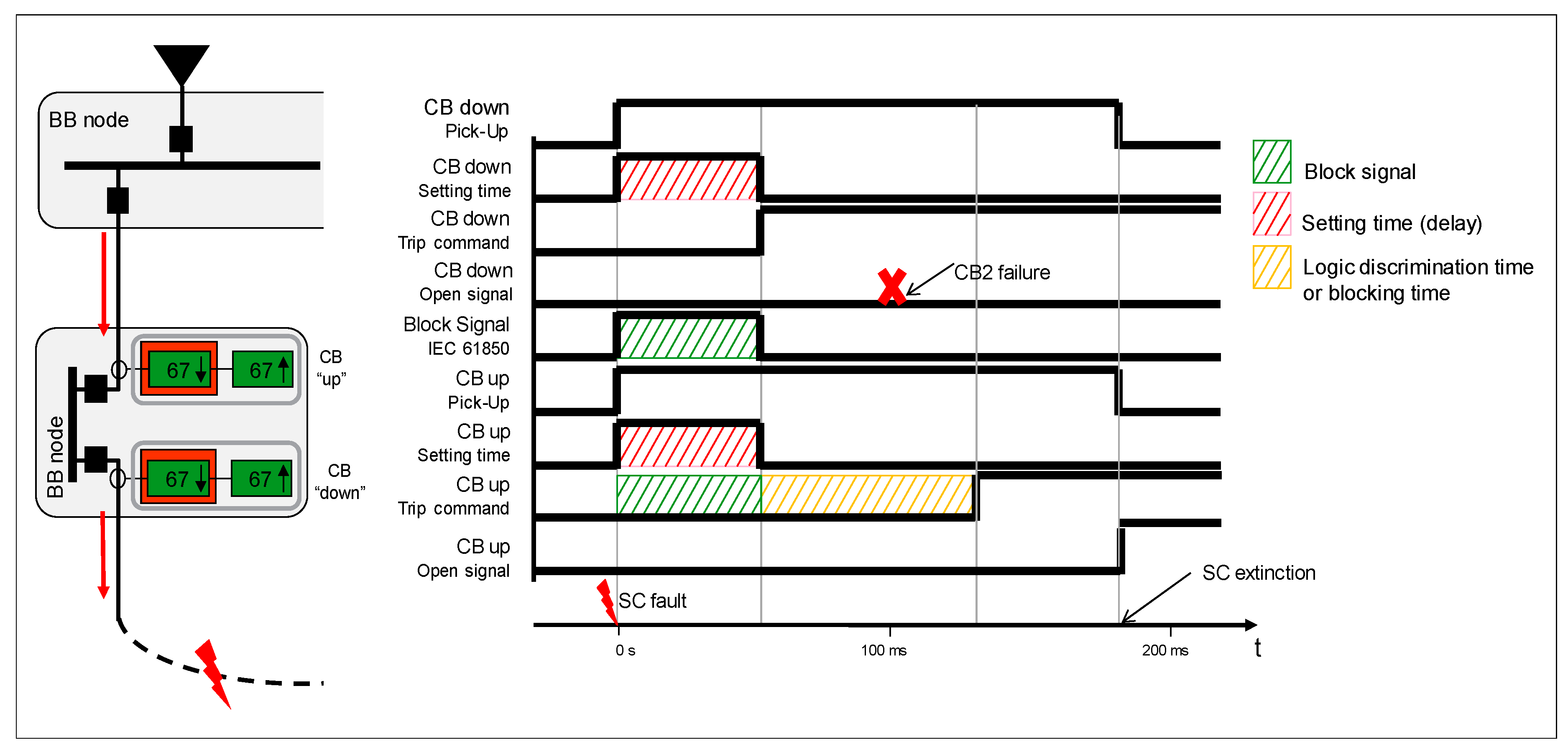
Figure 18.
Change of protection setting after GOOSE messages reception.

Table 1.
DER combination truth table.
| D1 | D2 | … | Di | … | Dm−1 | Dm | λ |
|---|---|---|---|---|---|---|---|
| 0 | 0 | … | 0 | … | 0 | 0 | 0 |
| 1 | 0 | … | 0 | … | 0 | 0 | 1 |
| 0 | 1 | … | 0 | … | 0 | 0 | 2 |
| … | … | … | … | … | … | … | … |
| 1 | 1 | … | 1 | … | 1 | 1 | n |
Table 2.
DS Information for each IED.
| IED | DATA SET | DATA | GOOSE |
|---|---|---|---|
| Incomer_GRID | DS_Island_Mode | Incomer_GRID.XCBR1.Pos.stVal | GRID_STATUS |
| Incomer_DER_X | DS_Connection | Incomer_DER_X.XCBR1.Pos.stVal | DER_STATUS |
| IED_X_RING | DS_Protection | IED_X_RING.PTRC.BlkInd1.stVal IED_X_RING.PTRC.BlkInd2.stVal | RING_PROTECTION |
Table 3.
Comparative analysis between IEC 61850 and traditional wiring.
| Discrimination with Traditional Wiring | Discrimination with IEC 61850 GOOSE | Obtained Benefits/Improvements |
|---|---|---|
| Dedicated wire for each signal | Using the communication network in the system | Cost reduction about 90% |
| Only one automation possibility | Multiple automation possibilities | Increase of the system flexibility |
| Expensive installation costs | Reducing installation costs | Installation cost reduction about 30% |
| Long time between latching | Reducing time between latching through GOOSE service | Latching time reduction about 70% |
| Unknown due to lack of confirmation or possible error | Safety system in front of a problem in a part of communication network | Increase of the system security |
© 2017 by the authors. Licensee MDPI, Basel, Switzerland. This article is an open access article distributed under the terms and conditions of the Creative Commons Attribution (CC BY) license (http://creativecommons.org/licenses/by/4.0/).
Share and Cite
MDPI and ACS Style
Silos, Á.; Señís, A.; De Pozuelo, R.M.; Zaballos, A. Using IEC 61850 GOOSE Service for Adaptive ANSI 67/67N Protection in Ring Main Systems with Distributed Energy Resources. Energies 2017, 10, 1685. https://doi.org/10.3390/en10111685
AMA Style
Silos Á, Señís A, De Pozuelo RM, Zaballos A. Using IEC 61850 GOOSE Service for Adaptive ANSI 67/67N Protection in Ring Main Systems with Distributed Energy Resources. Energies. 2017; 10(11):1685. https://doi.org/10.3390/en10111685
Chicago/Turabian StyleSilos, Ángel, Aleix Señís, Ramon Martín De Pozuelo, and Agustín Zaballos. 2017. "Using IEC 61850 GOOSE Service for Adaptive ANSI 67/67N Protection in Ring Main Systems with Distributed Energy Resources" Energies 10, no. 11: 1685. https://doi.org/10.3390/en10111685
Note that from the first issue of 2016, this journal uses article numbers instead of page numbers. See further details here.