A Market-Based Analysis on the Main Characteristics of Gearboxes Used in Onshore Wind Turbines


1
European Commission, Joint Research Centre, Directorate C-Energy, Transport and Climate, Westerduinweg 3, NL-1755 LE Petten, The Netherlands
2
Department of Electrical Engineering, School of Engineering, University of Seville, 41092 Seville, Spain
3
Department of Mechanical and Manufacturing Engineering, School of Engineering, University of Seville, 41092 Seville, Spain
*
Author to whom correspondence should be addressed.
Energies 2017, 10(11), 1686; https://doi.org/10.3390/en10111686
Submission received: 1 October 2017
/
Revised: 19 October 2017
/
Accepted: 20 October 2017
/
Published: 25 October 2017
Abstract
:Even though wind energy is one of the most mature renewable technologies, it is in continuous development not only because of the trend towards larger wind turbines but also because of the development of new technological solutions. The gearbox is one of the components of the drive train in which the industry is concentrating more effort on research and development. Larger rotor blades lead to more demanding requirements for this component as a consequence of a higher mechanical torque and multiplication ratio (due to lower rotational speed of blades while the rotational speed on the generator side remains at similar values). In addition, operating conditions become increasingly demanding in terms of reliability, performance, and compactness. This paper analyses the different gearbox arrangements that are implemented by manufacturers of onshore wind turbines, as well as their market penetration (including different aspects that affect the design of the gearbox, such as drive train configuration and turbine size). The analysis carried out shows a clear convergence towards gearboxes with three stages. However, there is a noticeable diversity in the types of gears used, depending to a large extent on the preferences of each manufacturer but also on the nominal power of the wind turbine and drive train configuration.
1. Introduction
Wind energy is the renewable source with the largest and most successful development in recent years. At the end of 2016, global cumulative wind energy capacity in the world reached 486.7 GW, with 54.6 GW of new capacity installed during 2016 [1]. These figures show the high relevance of wind energy in today’s energy generation scenario, as well as the high degree of maturity it has been acquiring in recent years.
This remarkable increase of installed capacity goes hand in hand with an intense technological development that includes different areas of engineering. Firstly, the development of new materials that are largely responsible for the upscaling process towards bigger machines (wind turbines with up to 164 m of rotor diameter and 9.5 MW of rated power such the Mitsubishi Heavy Industries Vestas V164-9.5 MW [2] are currently available in the market). Secondly, electrical and electronic engineering that is involved in the improvement of more flexible and robust electric generators and power converters. Thirdly, mechanical engineering through the design of new gearboxes, as well as implementing different solutions aimed at increasing the efficiency of the mechanical transmission process. Most of these innovations and areas of study have a wide impact on the configuration and design of the drive train of modern wind turbines.
The drive train of a wind turbine is a set of components that transmits the kinetic energy captured by the rotor blades to the electric generator. The configuration of this set of components is closely linked to the type of electrical generator and control system, so it is common to include in the description of the drive train arrangement, also the information about the electrical generator (i.e., synchronous or asynchronous) and converter (partial or total power).
Currently (second half of 2017) the most prominent drive train configuration on the market is a doubly fed induction generator (DFIG) [3], controlled by a partial power converter that is connected to the rotor of the electric generator. This configuration requires a gearbox between the electric generator and the wind turbine rotor in order to adapt the rotational speed of the blades to the operating speed of the asynchronous generator. Therefore, in this configuration, the conversion from mechanical into electrical energy is performed in two steps: (i) conversion of kinetic energy at low rotational speed to medium/high rotational speed by the gearbox; and, (ii) conversion of kinetic energy into electrical energy by the electric generator.
Nevertheless, an alternative arrangement with increasing market impact is the so-called direct drive configuration, which consists of a synchronous electric generator directly coupled to the rotor blades and a full power converter to adapt the frequency to the typical operating conditions of the main electric grid (i.e., 50 or 60 Hz). For a long time, the direct drive configuration was expected to be the dominant arrangement in the future wind power market. The reason was that it presents several advantages, such as better operational flexibility, higher performance at partial loads (in the case of using a synchronous permanent magnet-based generator), and, in particular, it allows for the gearbox to be dispensed, with the consequent advantage of obtaining a more compact nacelle and lower maintenance costs inherent to a mechanical element, such as the gearbox.
In contrast, the direct drive requires a full power converter (which is more expensive than the partial converter used in DFIGs) and a synchronous electric generator with a relatively high number of poles (which leads to larger generator rotors of bulkier and heavier machines). The need for a greater number of poles is linked to the rotational speed of the blades: the smaller the rotational speed is, the higher the number of poles is required. As a consequence of the current trend towards larger wind turbines, the rotational speed of blades is becoming slower in order to limit the blade tip speed, thus avoiding mechanical overstress. This means that very bulky and heavy electrical generators would be required (in case of direct drive configuration), which would considerably increase the generator costs (especially in the case of permanent magnet-based generators, since the amount of rare metals required increases substantially), as well as the costs of other structural elements, such as the tower and foundation. For this reason, an increasingly common trend adopted by wind turbine manufacturers in the large wind turbines is to use a hybrid configuration consisting of a synchronous generator controlled by a full power converter and a gearbox to increase the operating speed of the generator and reduce its size and cost.
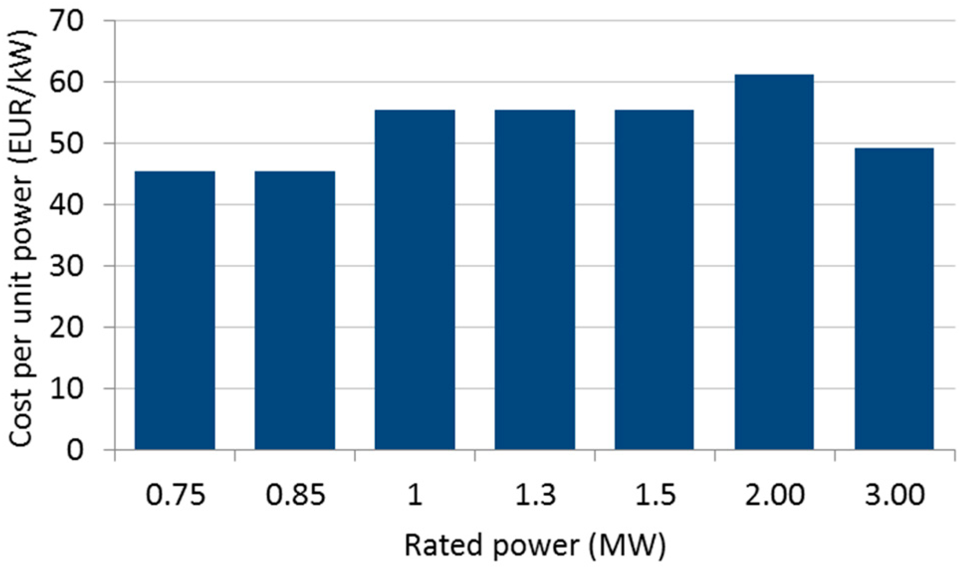
In light of the above, it can be assured that gearboxes are and will continue to be a key component in modern wind turbines. In addition, it is also worth noting that the gearbox plays an important role in the breakdown of costs, comprising typically between 6–19% [4,5,6] of the total upfront costs of geared wind turbines (these values largely depend on whether shafts and bearings are included in the cost analysis). Also, as wind turbines become larger and require higher transmission torques while maintaining the maximum possible compactness, the cost per unit of power of gearboxes is expected to increase. This fact can be observed in Figure 1, which shows the trend of gearbox cost depending on wind turbine rated power in the Chinese market in 2011 [7]. An exception can be observed in gearboxes for 3 MW wind turbines, which achieved an average cost per unit power at similar values than the gearbox for 750/850 kW wind turbines. This can be explained by a high demand of gearboxes in the 3 MW wind turbines and a high standardisation of the production process.
For the reasons outlined above, this article analyses the different gearbox alternatives, with a special emphasis on the advantages and disadvantages of each of them. It additionally examines the market penetration of each type of gearbox according to the drive train configuration and the rated power of the wind turbine.
There is a vast existing literature on describing technological features of wind turbines. In 2000, Ackermann and Söder [8] published a thorough description of the state of the art of the wind turbine technology. This work was updated and extended in 2002 [9]. In 2003, Carlin et al. [10] studied the capability of operating at variable-speed for different drive train configurations, taking into account then-recent developments on power electronics. Along the same lines, in 2004 Hansen et al. [11] classified wind turbines in four configurations according to their speed-control capability (i.e., drive train configuration). In 2007, Herbert et al. [12] presented the latest technological developments on aspects such as aerodynamics, wind resource assessment, or reliability. Also in 2007, Hansen and Hansen [13] presented a market-based study of wind technology by mainly analysing the worldwide evolution of drive train configuration and power control systems from 1995 to 2004. In 2011, Kaldellis and Zafirakis [14] analysed the evolution of rated power and rotor diameter, as well as the market share of stall-regulated versus pitch-regulated wind turbines. Also in 2011, Llorente et al. [15] analysed the evolution of wind turbine topologies with a specific focus on their power electronics content. Serrano and Lacal [16] presented in 2016 a market-based study that complemented the work published by Hansen and Hansen [13], analysing the technological trends in wind turbines over the period 2005-2014. In 2017, Vázquez, Telsnig and Villalba updated the previous analysis by examining different technological indicators up to 2015 [17].
With regard to studies on different aspects of gearboxes for wind turbines, two areas with an intense research activity can be highlighted: (i) arrangements and alternative designs of gearboxes that could reach the market in the future; and, (ii) reliability issues. In the first area, there is a noticeable research interest in applying the following alternative gearbox designs in wind turbines:
- Continuously variable transmission (CVT) [18,19], which would allow for assembling synchronous generators that are directly connected to the grid, thus avoiding the power converter [20]. A CVT allows for continuously varying the global transmission ratio by adapting in real-time operation the input speed (at the blades) into the instantaneous speed requirements at the output (i.e., the input of the electric generator) [21]. In this sense, recent research has analysed the use and performance of CVTs in drive trains of wind turbines, as it is the case of Giallanza et al. [22] proposing a solution in low-wind sites, or Wu et al. [23] providing speed control for the permanent magnet synchronous generator as the speed regulator in the CVT at wind turbines. The explorations of new alternatives of drive trains making use of the novel concepts of CVTs, such as inertia regulating systems [24,25], are also being explored. This would enable the regulation of the output angular velocity, thus minimizing failures by absorbing overloads through the inertial subsystem.
- Hydraulic transmissions, which are also continuously variable (i.e., power converter may be dispensed), as well as lighter and cheaper than conventional gearboxes [26]. On the contrary, their performance is still low; large diameter generators assembled with hydraulic transmissions would enable the reducing of the amount of structural material in the generator [27,28], although protecting windings and magnets against environment conditions may be an issue.
- Magnetic pseudo direct drive train, in which the magnetic gear and the electric generator are integrated in the same machine. This device would be around 50% smaller in terms of mass and size than conventional direct drive with permanent magnets generator [26]. Additionally, the absence of rolling and frictional elements would reduce losses and improve reliability although a significant number of permanent magnets are required in this drive train configuration.
In addition to research on alternative gearbox concepts, there is also very active research on solutions to increase the reliability of the gearbox, which is usually seen as one of the least reliable parts of geared wind turbines. Nevertheless, according to the several studies [29,30], it can be concluded that the electrical and electronic systems (i.e., the power converter), as well as the pitch control system, cause more failures. In any case, the gearbox usually causes more downtime that any other turbine sub-assembly so the reliability of this component needs to be improved and new techniques to monitor and detect electrical and electronic failures must be developed. Current monitoring systems mainly focus on the generator, gearbox, and main bearings and are mostly based on vibration detection, which is a good technique to identify gear and bearing problems. The research also focuses on several areas such as new algorithms to detect possible faults based on the measurements provided by the Supervisory Control and Data Acquisition (SCADA), used in almost all modern wind turbines to operate the machine [31,32]. Another subject of intense research is the development of specific condition monitoring systems to detect possible malfunctioning or failures in the turbine, consisting of both research on hardware (new sensors and modules) and the conception of new detection algorithms.
The literature review reveals a lack of studies analysing and identifying the gearbox configurations that are actually used by the industry. Therefore, this work fills in the gap existing in market-based analysis on the use of gearboxes in wind turbines by following a similar methodology used by other authors in previous works aimed at examining other technological aspects of wind turbines [11,13,16]. In addition, it complements other existing studies on gearboxes, allowing future researchers to identify the most relevant types of gearboxes. The present study is based on data collected by the Joint Research Centre (JRC) of the European Commission in the JRC Wind Energy Database. This database contains technical data of more than 29,000 (This number may differ from the actual number of wind farms installed in the world because different phases or wind turbines (officially belonging to the same farm) connected to the grid in different years are considered as independent entries to the database) onshore wind farms installed worldwide, totalling 440 GW of cumulative installed capacity. This represents 93% of the onshore capacity declared by the Global Wind Energy Council (GWEC) at the end of 2016 [33].
After this introduction, the rest of the paper is organized as follows: Section 2 depicts the gearboxes typologies currently used in modern wind turbines, Section 3 describes the different drive train arrangements employed by wind turbine manufacturers and highlights the relevance of each configuration according to actual market data, and Section 4 studies the evolution of the market penetration of each gearbox type. Finally, conclusions and final remarks are included in Section 5.
2. Gearbox Typologies and Description
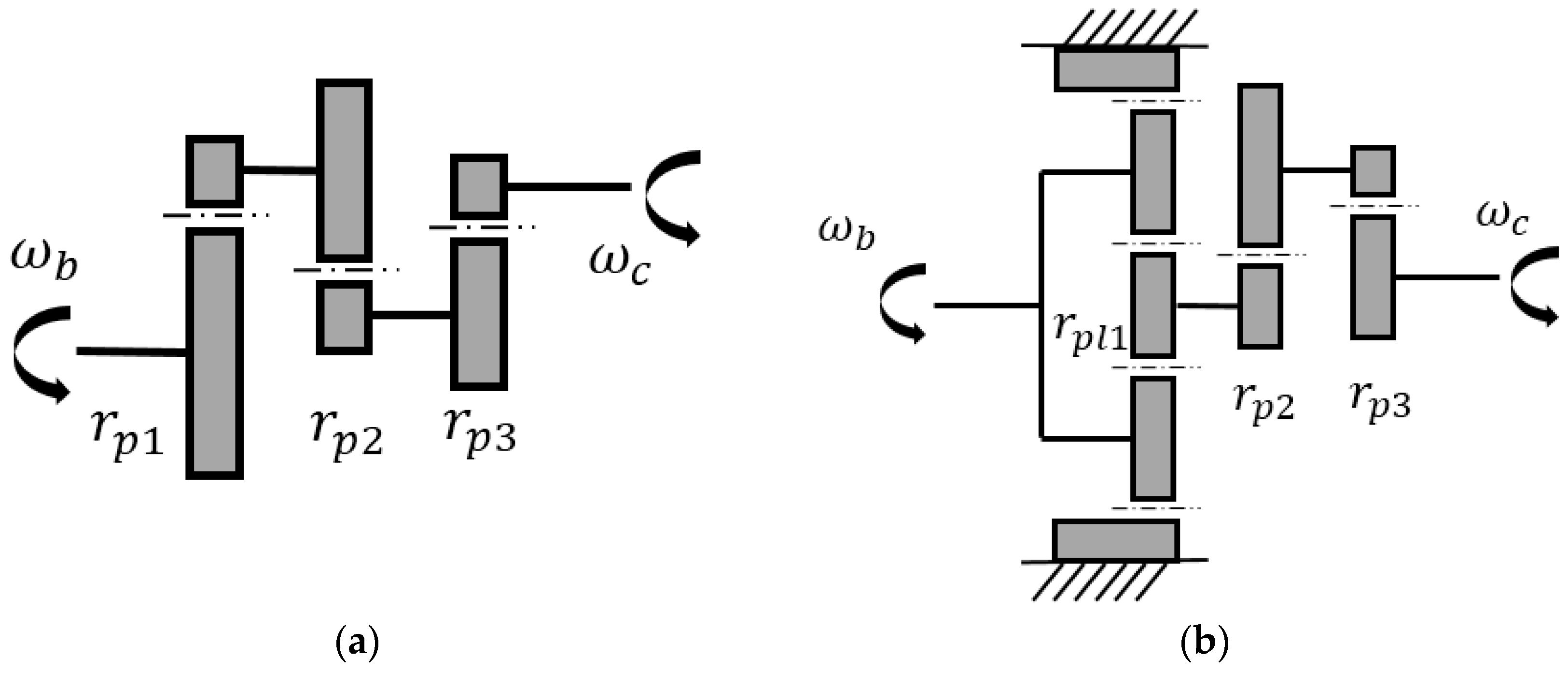
A wind turbine gearbox usually consists of several (usually three) multiplication stages, which are made up of only parallel gears, only planetary gears, or a combination of both gears types, i.e., parallel stages assembled with planetary stages. Two typical examples of 3-stage gearbox configurations are shown in Figure 2.
Each gear type has a series of advantages and disadvantages that can be summarized as shown in Table 1. Although there are some differences between the two types of parallel gears (i.e., helical or spur), they are equally represented in a schematic representation (such as Figure 2), and for this reason, some manufacturers do not specify the actual type in the wind turbine data sheet. In this sense, they are both treated below as generic parallel gears. Additionally, planetary stages content a sun gear (an outer gear known as annulus) and a series of planet gears (at least 3) hold together by a movable arm or carrier. In the gearbox, they provide the multiplication transmission by blocking the annulus (as can be seen in Figure 2b).
The use of planetary instead of helical or spur gears is justified by the following main reasons: (i) the same global multiplication ratio Rg can be achieved with a lower axial and/or radial dimensions providing a compact design in cases where high multiplications ratios are needed (as in medium/high power wind turbines); (ii) planetary gears allow the minimization of the losses of power attained in conventional parallel gear couples [34,35] (being the losses higher in helical than in spur gears) and (iii) higher mechanical torques are needed to be transmitted.
Figure 2a displays an example of a typical configuration of a fully-helical (or spur) gearbox (only containing parallel gears), whereas Figure 2b depicts a hybrid gearbox (one planetary plus two parallel stages). This latter has a first planetary multiplication stage with ratio rpl1 followed by two helical gears with multiplication ratios of rp2 and rp3. The relation of the input velocity, ωb, (blades rotational speed) to the output velocity, ωc, (the generator rotational speed) is as follows:
where Rg is the global multiplication ratio comprising the different stages of the gearbox within the wind turbine drive train.
ωc = Rg × ωb = (rpl1 × rp2 × rp3) × ωb
Every stage has the aim of converting the input mechanical power, which is characterised by a lower angular velocity and a higher torque, into a higher output angular velocity transmitting a lower torque. Assuming an ideal mechanical behaviour (no power losses through the transmission system), the conservation of mechanical power would be represented by Equation (2):
where P, T, and ω are the mechanical power, torque, and angular velocity, respectively.
Pmech = Tinput × ωinput = Toutput × ωoutput
It must be pointed out that in the case of using one or more planetary stages, they are usually placed close to the input (1st and/or following stages) in order to resist the high torque levels transmitted by the blades in these initial stages, as can be easily deduced from Equation (2).
3. Drive Train Arrangements
As stated in the introduction section, the drive train converts the mechanical power captured by the wind turbine rotor blades into electric power. The steps involved in this conversion, and hence the drive train components, depend on the configuration. Hansen et al. [11] presented a wind turbine classification that has been widely used in the existing literature. This classification was further extended by Serrano and Lacal [16], also including hybrid arrangements with full power converter and gearbox. A brief description of this classification is provided in the following lines (see also Figure 3):
- Type A. Fixed-speed generator. No power converter neither other speed regulation techniques are used in this configuration. The operating speed of an asynchronous electric generator (i.e., high-speed generator, which in wind technology operates usually at around 1500 rpm) is constrained by the rotational speed of the rotor blades (according to a certain multiplication factor fixed by the gearbox ratio and the number of poles of the generator).
- Type B. The speed of the asynchronous generator is controlled by a variable resistance that enables modifying the circulating current in the rotor of the electrical generator. This solution provides higher control flexibility than Type A. However, the electrical losses are relatively high and the response to grid requirements is limited.
- Type C. This configuration is known as doubly-fed induction generator (DFIG). The current in the electric generator’s rotor is controlled by a power converter. Thus, electrical losses are lower and the response to grid requirements is enhanced. Since the power converter is only connected to the rotor of the generator, the rated power of the converter is around 30% of the rated power of the wind turbine.
- Type D. A full power converter enables the decoupling of the generator from the grid frequency so that the frequency on the generator side can be fully controlled and the use of a gearbox can be avoided. Additionally, the full power converter provides enhanced grid services. A synchronous electrical generator (which can be either an electrically excited synchronous generator (EESG) or a permanent magnet synchronous generator (PMSG)) is directly coupled to the main shaft of the rotor (which operates at a rotational speed around 5–40 rpm, depending on the wind turbine size).
- Type E. Gearbox-equipped wind turbine with a full power converter and medium/high-speed synchronous generator, which can be EESG or PMSG. This configuration enables reducing the size of the generator (compared to Type D), while maintaining the advantage of using a total power converter (with greater grid capabilities). In this arrangement, it is possible to choose between a relatively small gearbox (with moderate gear ratios) at the expense of using a large medium-speed (about 500 rpm) synchronous generator. On the other hand, it is possible to assemble a gearbox with a higher gear ratio in order to reduce the size of the generator, being a high-speed configuration with synchronous generator.
- Type F. Gearbox-equipped wind turbine with a full power converter and high-speed asynchronous generator. As the full power converter enables the speed to be controlled by modifying the operating frequency, a squirrel cage induction generator (SCIG) is generally employed in this configuration.
Figure 4 shows the evolution over the period 2010–2016 of geared and gearless wind turbines in the markets under study: Europe, Asia, North America, and the rest of the world (hereafter as RoW). A dominant role of the geared turbines can be clearly appreciated in all of the markets, although the incidence of gearless wind turbines has increased over the years in the European and Asian (Please note that the quality of the results for the Asian market is relatively limited in the period 2013–2015, due to the low availability of public data) markets. Nevertheless, in general terms, this trend is reversed in the last years with a rebound of the market penetration of geared wind turbines, especially in 2015–2016 in Europe, in 2016 in Asia and in 2014–2016 in North America and the RoW.
Figure 5 expands the information shown in Figure 4, breaking down the drive train arrangement according to the classification introduced above in this section. As observed, high-speed geared wind turbines—with either (i) doubly feed induction generator or (ii) full power converter plus squirrel cage induction generator—are the dominant configuration over the period analysed. The gearless configuration Type D also has an important but decreasing market share.
Even though this arrangement was expected to dominate the market, as mentioned in the introduction section, the trend towards larger wind turbines with a slower rotational speed requires electric generators with larger number of poles (and hence heavier machines). This has slowed down the impact of gearless wind turbines in the market in favour of hybrid wind turbines with full power converter and synchronous generator (i.e., geared wind turbines with medium- or high-speed generators). This tendency can be especially observed in Europe and North America, where Type E and Type F configuration is gaining prominence, respectively. On the contrary, Types A and B configurations have steadily decreased and they currently represent a marginal market share of new installed capacity.
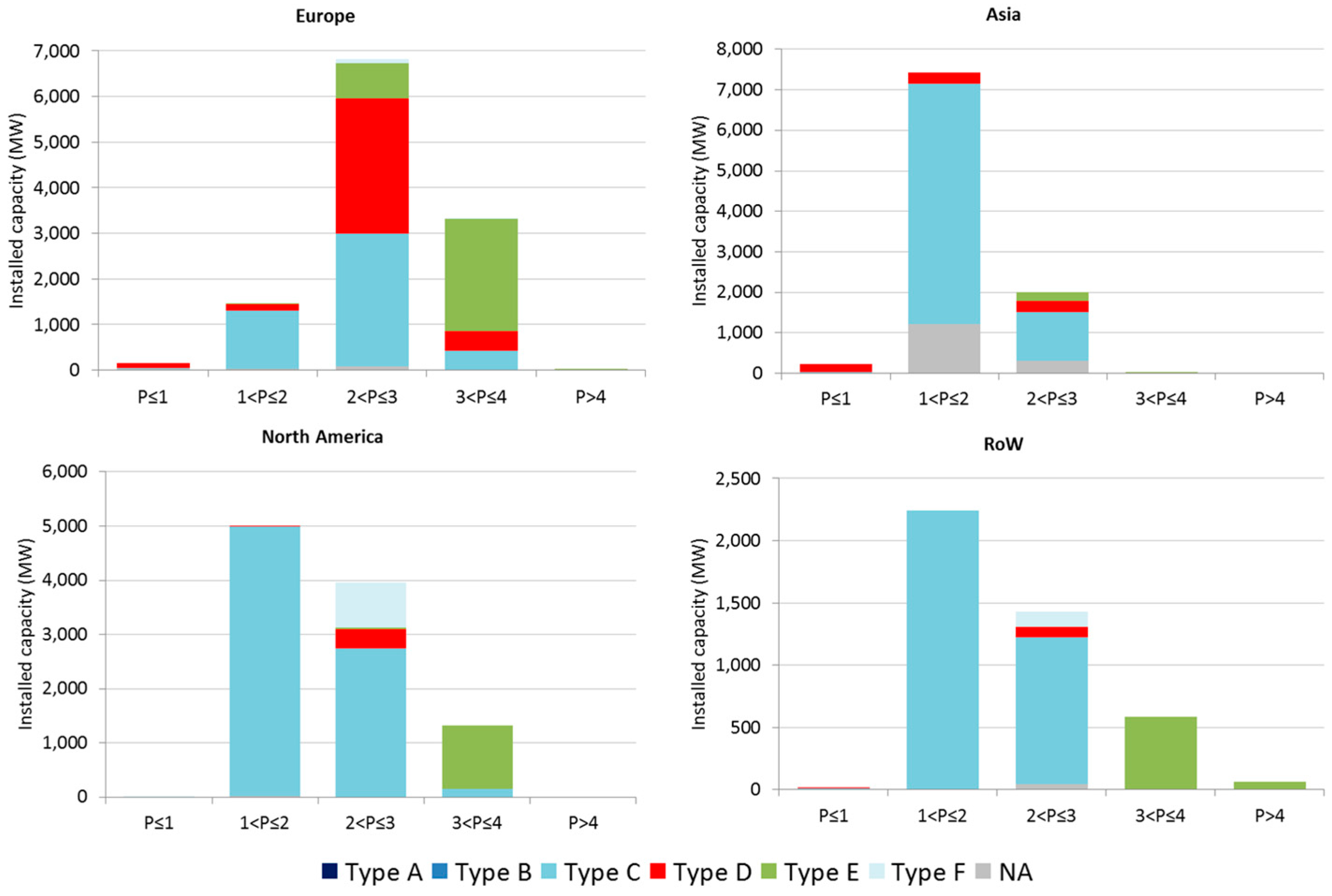
Figure 6 shows the types of drive train configuration employed in onshore wind turbines installed in 2016 classified according to the wind turbine rated power and the geographical zone. As observed, the drive train configuration is closely related to the wind turbine nominal power. Most wind turbines below 2 MW make use of high-speed geared wind turbines with Type C configuration, although this arrangement loses market share as nominal power increases. In 2–3 MW wind turbines, gearless configuration Type D had a similar share than Type C in the European market (43%) in 2016. The hybrid arrangements Type E and F only represented 11% and 1%, respectively, of the European market in the 2–3 MW range. Conversely, Type F configuration (Siemens supplies all of the wind turbines of this arrangement) reached a relevant role in North America in 2016 by representing 21%. Unlike Europe, Type D configuration only represented 3% in North America in the 2–3 MW range. In wind turbines larger than 3 MW, the hybrid arrangement Type E was the preferred solution in all of the markets in 2016. It covered the whole market share in Asia and the RoW, and it represented 89% and 73% in North America and Europe, respectively.
To sum up, the overall evaluation of the wind turbine rated power depicted in Figure 6, shows that there exists a prevalence of 2–3 MW turbines in Europe (with almost 50–50% of drive train arrangements Types C and D) but also an important number of high powerful wind turbines (larger than 3 MW and consisting especially on the hybrid configuration Type E), whereas the North American, Asian and RoW markets are mainly dominated by 1–2 MW wind turbines with drive trains of Type C.
4. Gearbox Market-Based Analysis
This section focuses on the gearbox arrangements used for each type of geared drive train, i.e., Types A, B, C, E, and F. Type D arrangement is excluded from the analysis as it does not require a gearbox. In this sense, Figure 7 shows the number of stages of the gearboxes of these drive train configurations in the global onshore wind market. As observed, the 3-stage gearboxes have a prominent role representing at least 60% of the global market, followed far by the 2-stage gearboxes only amounting by 4%. 1-stage and 4-stage gearboxes display a marginal share.
Based on the drive train configuration, the Types C and F arrangements are almost and totally dominated by 3-stage gearboxes representing at least 90% and 100%, respectively. Even though the 3-stage gearboxes also prevail in the Types A, B, and E, 2-stages gearboxes play a relevant role amounting by 32% in Types A and B and 12% in Type E. The 4-stage gearboxes are marginally used in wind turbines with Type C and Type E, mainly due to the higher torque to be transmitted.
Figure 8 displays the evolution of the number of gearbox stages in geared drive train configurations in the global onshore market in the period 2010–2016. In Types A and B, 3-stage gearboxes hold a dominant position over the years, whereas 2-stage gearboxes display a decreasing tendency with the exception of the growth shown in 2015. As previously discussed, for both Types C and F, the 3-stage gearbox is the absolute dominant configuration during the period considered. Regarding Type E, the current trend towards wind turbines with higher nominal power and more compact synchronous generators has led to the use of gearboxes with a higher gearbox ratio and, therefore, a greater number of stages. As a consequence, 2-stage gearboxes display a severe decrease from 2010 almost disappearing in the new installed from 2014 onwards. Additionally, 1-stage gearboxes were assembled in this drive train configuration in only 2010. The lower role of 1- and 2-stage gearboxes is due to the higher presence of medium-speed synchronous generators at the beginning of the decade for this arrangement.
The number of stages of gearboxes also displays a relationship to the wind turbine rated power. Figure 9 shows the number of stages of the gearboxes in geared drive trains classified according to wind turbine nominal power in the global onshore wind market. The 2-stage gearboxes are mainly installed in wind turbines with low nominal power, in particular, below 2 MW in Types A and B drive trains and 2–3 MW in Type E. The 1-stage gearboxes are only assembled with the less powerful generators of the Type E configuration amounting a nominal power below 1 MW. As previously shown in Figure 7, Types C and F drive trains are dominated by a 3 stage-gearbox coupled to an asynchronous generator regardless of the wind turbine nominal power.
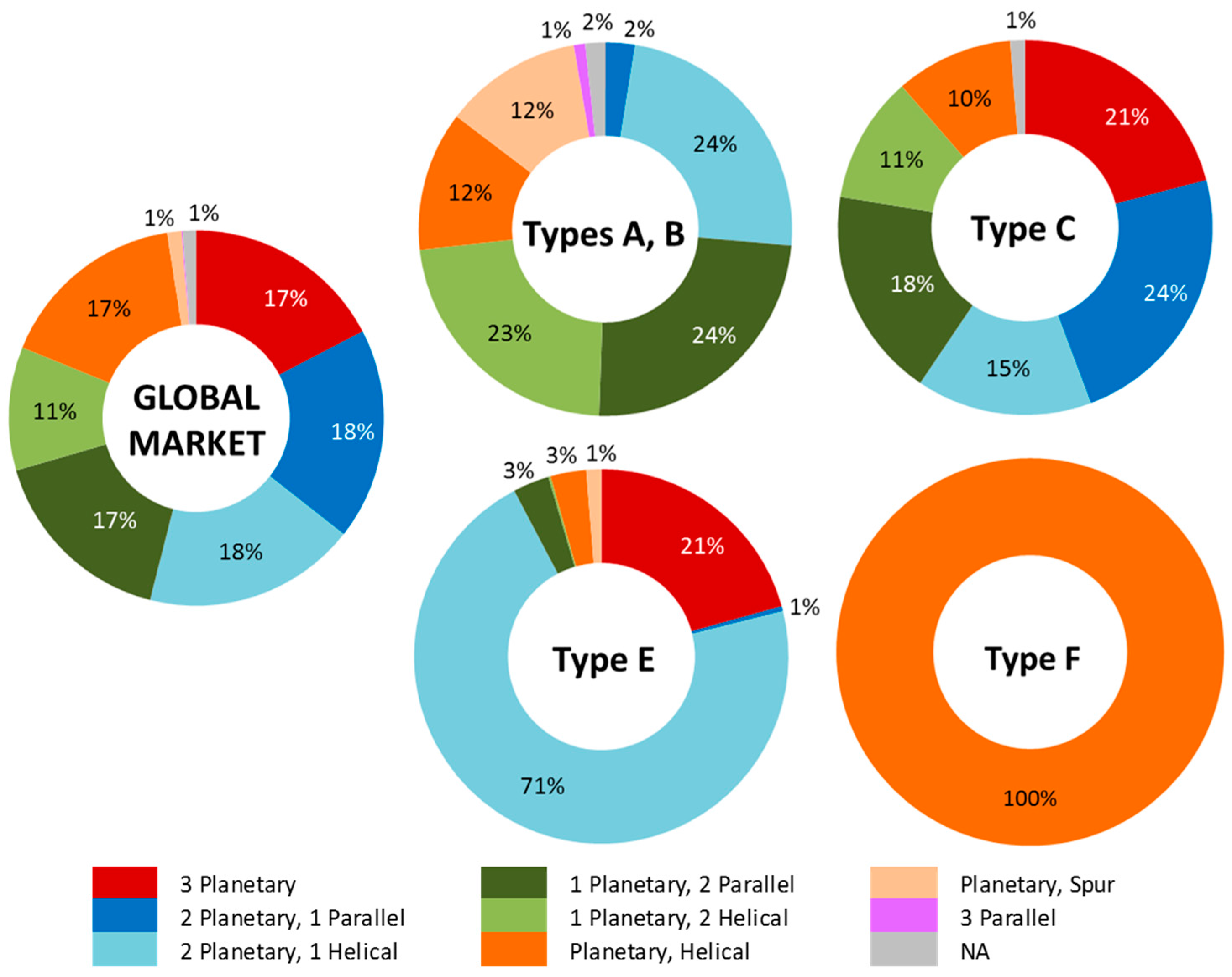
Figure 10 displays the types of gears used in 3-stage gearboxes for all of the drive train types in the global onshore wind market. As observed, the 3-stage gearboxes with 2 planetary stages have a prominent role representing at least 36% of the installed capacity in the global market, followed by 1 planetary stage amounting at least 28%. 3 planetary stages also display a relevant share with 17% of the global installed capacity.
Based on the drive train configuration, in Types A and B (mainly implemented in wind turbines with nominal power below 2 MW) most of 3-stage gearboxes combine the use of either 1 planetary stage (identified in 47% of installed capacity of these configurations) or 2 planetary stages (in 26% of installed capacity) with 2 or 1 parallel stages, respectively. On the contrary, the gearboxes consisting of three planetary stages exclusively are not used in these drive train configurations due to the lower transmission ratio and compactness requirements for those rated power levels. In Type C configuration using 3-stage gearboxes, the planetary stages have a more dominant role in order to transmit the resistance of the torque at the initial stages, being able to provide the required transmission ratio while maintaining the gearbox compactness. Thus, three planetary stages represent 21% of installed capacity of this configuration and two planetary stages have a dominant role by amounting to 39% of the installed capacity. Unlike Types A and B configurations, one planetary stage has a lower role with 29% of installed capacity. The 3-stage gearboxes in Type E arrangement are dominated by two and three planetary stages representing 72% and 21% of installed capacity, respectively. As mentioned in Section 3, in Type E configuration it is possible to achieve a trade-off between two opposing effects (the gearbox size and the asynchronous generator size). This fact, along with the high-power ratings of wind turbines using this configuration, makes compactness a priority and further encourages the use of planetary stages. Type F configuration uses planetary/helical gearboxes although it has not been possible to identify the actual number of planetary stages in this configuration.
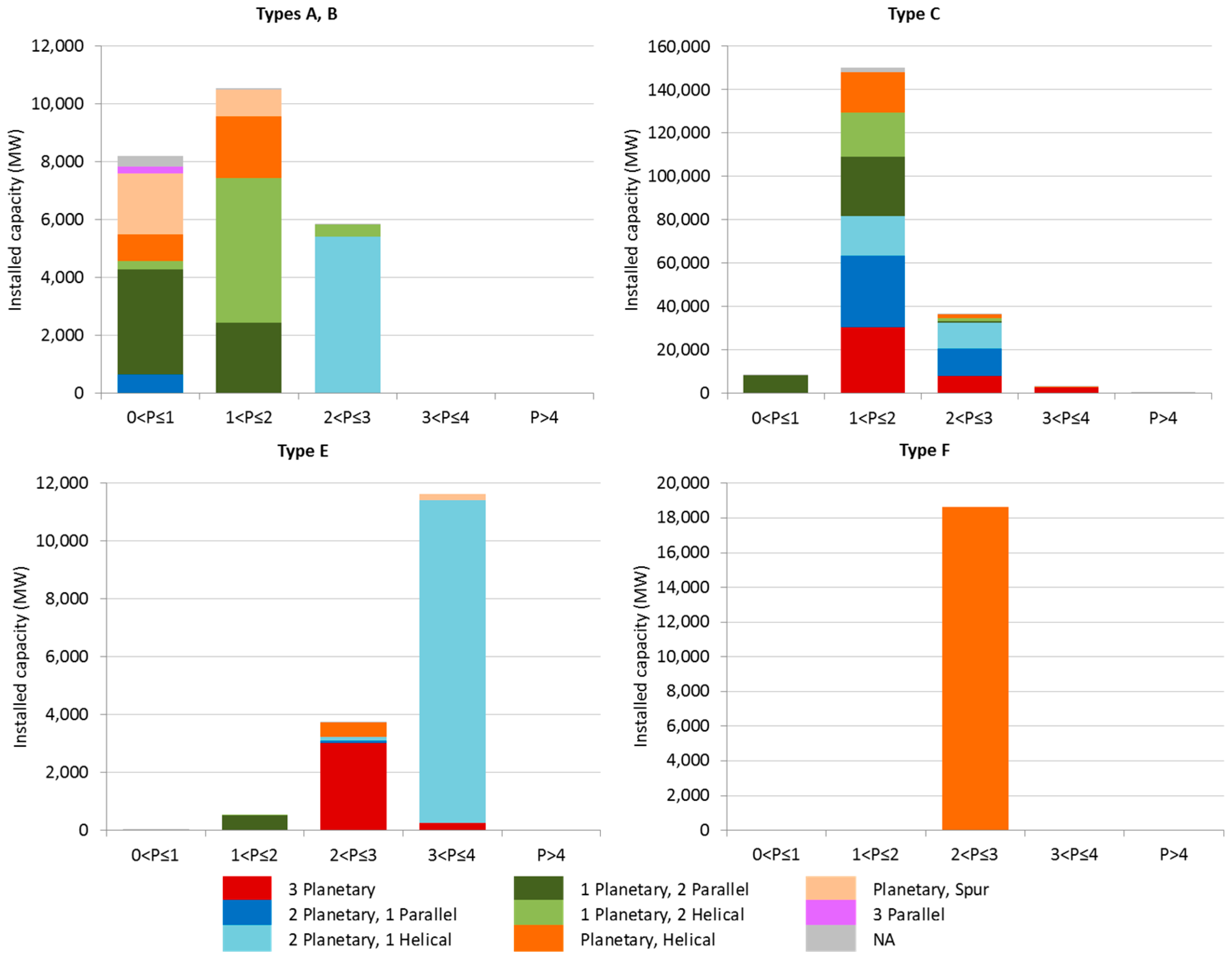
Figure 11 shows the same information as Figure 10 but categorizing the types of gears used in 3-stage gearboxes by wind turbine rated power. As observed, in Types A and B there is a direct relationship between the number of planetary stages and the wind turbine nominal power: two planetary stages are almost exclusively installed for the highest rated power in this drive train configurations (2–3 MW), whereas one planetary stage predominates in lower nominal power (below 2 MW). In addition, three parallel stages are exclusively installed in wind turbines with low rated power (below 1 MW).
As it happens in Types A and B, two planetary stages prevail in wind turbines with Type C configuration and high nominal power (i.e., above 2 MW) also displaying a dominant share in the range 2–3 MW. On the contrary, one planetary stage predominates in wind turbines with nominal power lower 1 MW. Three planetary stages display an increasing share in the installed capacity as wind turbines have a higher nominal power.
In type E, the wind turbines with rated power above 3 MW are dominated by 3-stage gearboxes with two planetary stages, whereas three planetary stages are dominant in nominal power ranging 2–3 MW.
Another important characteristic of the gearbox to be analysed is the gearbox ratio (GR), also referred above as global multiplication ratio (Rg), which comprises the different stages of the gearbox within the wind turbine gearbox. Along the subsequently gearbox stages, every one of them has the aim of converting the input mechanical power characterised by a lower angular velocity and a higher torque, into a higher output angular velocity transmitting a lower torque. The multiplication gearbox ratio is then defined as the ratio between the output and the input angular velocity, which is inversely proportional to the torque ratio, as was explained in Section 2.
Figure 12 shows the percentage of global cumulative installed capacity corresponding to different ranges of the gearbox multiplication ratio according to the number of gearbox stages. As expected, the smaller the number of stages is, the lower the overall GR (gearbox ratio) is. For 1-stage gearboxes (configuration with some relevance only for drive train Type E and rated powers below 1 MW), the gearbox ratio ranges from values 20:1 to 80:1. In the case of 2-stage gearboxes (only relevant for drive trains Types A and B as well as for the medium/high-speed hybrid configuration, Type E), the variety of gearbox ratios is larger, ranging from 20:1 to 100:1 (with some marginal presence of two-stage configurations below and above these values). Finally, in 3-stage gearboxes (corresponding to the majority of gearboxes used in modern turbines, and virtually all high-speed wind turbines for drive train Types C and F), the diversity of gearbox ratios increases considerably, ranging from around 40:1 to even above 120:1.
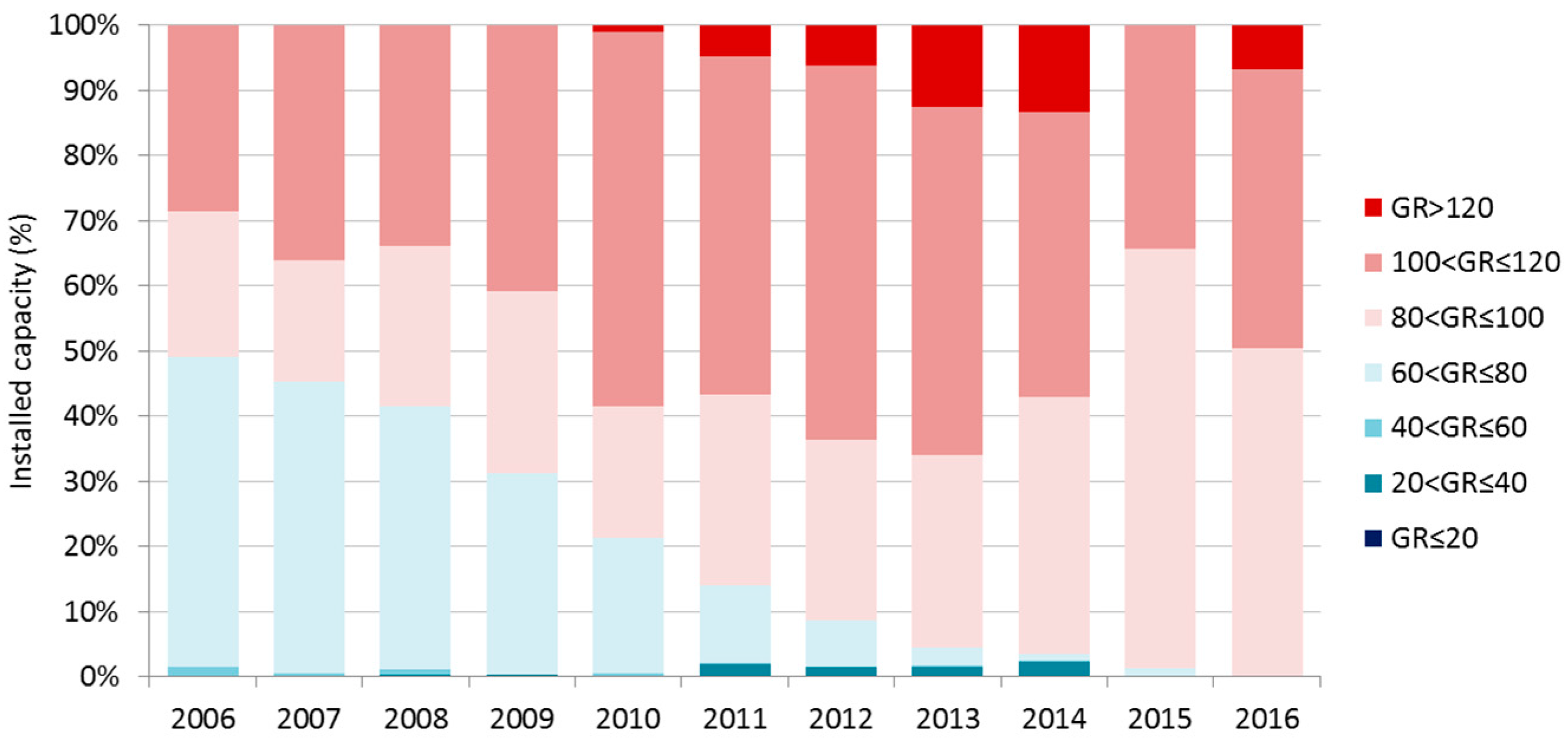
Figure 13 represents the evolution of the gearbox multiplication ratio from 2006 to 2016. As observed, there is a trend towards higher multiplication ratios, with a clear convergence to GR values in the range 80:1–120:1 and a significant decline of GRs below 60:1, achieving a marginal role at the end of the period under study. Nevertheless, from 2010 onwards, GRs in the range 100:1–120:1 seem to lose market in favour of more moderate ratios (around 80:1–100:1). It is also worth mentioning that there is a growing presence of very high multiplication factors (above 120:1) during the period 2010–2014. Even though this trend seems to be reversed in 2015, these higher GRs emerge again in 2016. These recent trend changes, towards slightly lower gearbox ratios, are the result of a greater market penetration of the Type E drive train configuration (in which the multiplication factor can be reduced at the expense of installing larger generators). Finally, it is also worth noting the very moderate role of extremely low GRs (below 40:1) in the period 2011–2014, corresponding to medium speed turbines, under the Type E drive train configuration.
5. Conclusions
This paper presents a prospective study on the current market penetration of the different types of gearboxes that are used in onshore wind turbines. With this purpose, actual market and research data of operating wind power plants have been used.
The study reveals the existence of a wide variety of gearbox types implemented by wind turbine manufacturers in the onshore wind market. This variety is the result of the continuous technological evolution undergoing in the wind power industry, not only towards larger wind turbines, but also towards more efficient, reliable, and economically competitive solutions. In addition, the current trend towards larger wind turbines (in terms of both rotor size and rated power) has somewhat reversed the past tendency towards gearless wind turbines, which is a consequence of the need for very large, heavy, and expensive electric generators (in the case of gearless wind turbines, in which the shaft of the electric generator is directly coupled to the turbine rotor).
In this context, the current industrial strategy of wind turbine manufactures is using gearboxes with two or three stages, usually combining parallel stages with one or two planetary stages or even three planetary stages, depending mainly on the nominal power of the wind turbine. More specifically, Types A and B arrangements (corresponding usually to low rated power) make use of 2-stage and mainly 3-stage gearboxes. In this latter, 1 planetary stage is the main configuration followed by two planetary stages. In drive train configurations usually employed for higher nominal power, 3-stage gearboxes are the preferred configuration. In particular, Type C configuration (predominant in 1–3 MW nominal power) mainly uses two planetary-one parallel arrangement followed by one planetary-two parallel and three planetary stages. In Type E configuration (mainly used in 2–4 MW nominal power), the presence of two planetary-one parallel and three planetary stages is more dominant.
Apart from the implications of the different types of wind turbines using a number of possible gearbox configurations, the gearbox multiplication ratio has also been analysed as an important parameter of design. In general terms, there is a clear trend towards high multiplication ratios in the range of 80:1–120:1 (due to ever larger machines). However, other identified sub-tendencies regarding gearbox multiplication ratio are worth to be mentioned: (i) gearboxes with gear ratios of less than 80:1—which in the past accounted for around 50% of the market—now play a marginal role; (ii) the growing market penetration of hybrid turbines (Type E) has somewhat reversed the need to use very high gear ratios for large wind turbines; and, (iii) despite of the fact that hybrid configuration with medium-speed generators (and small gear ratios of gearboxes) has been an alternative explored in the past by the wind power industry, it appears that this option has been discarded and its current impact on the current market is quite limited.
Overall, the analysis shows that there is no clear convergence towards a single best gearbox configuration and all configurations are continuously evolving. Therefore, it is still a very active field of research and development, and new configurations may potentially achieve significant market shares in the future.
Acknowledgments
This work has been supported in part by the project “Management of knowledge in energy research, innovation and competitiveness” (246-RIC KM), work package 765-SETIS-SET-Plan Information System carried out by the Joint Research Centre-European Commission.
Author Contributions
Cristina Vázquez conducted the data collection and contributed to the analysis of the results and the writing the manuscript. Javier Serrano contributed to the study of drive train arrangements and collaborated in the analysis of the results and the writing of the manuscript. Gabriel Centeno contributed to the description of gearbox typologies.
Conflicts of Interest
The authors declare no conflict of interest.
References
- Global Wind Energy Council (GWEC). Global Wind Energy Outlook. Available online: http://gwec.net/publications/global-wind-energy-outlook/ (accessed on 16 August 2017).
- MHI Vestas Offshore. The World’s Most Powerful Available Wind Turbine Gets Major Power Boost. Available online: http://www.mhivestasoffshore.com/worlds-most-powerful-available-wind-turbine-gets-major-power-boost/ (accessed on 25 August 2017).
- Lacal-Arántegui, R.; Serrano-Gonzalez, J. 2014 JRC Wind Status Report; Publications Office of the European Union: Luxembourg, 2015; ISBN 978-92-79-48380-6. Available online: https://ec.europa.eu/jrc/en/publication/eur-scientific-and-technical-research-reports/2014-jrc-wind-status-report (accessed on 10 September 2017). [CrossRef]
- Fingersh, L.; Hand, M. Wind Turbine Design Cost and Scaling Model. Available online: http://large.stanford.edu/courses/2015/ph240/anderson2/docs/40566.pdf (accessed on 12 September 2017).
- Moné, C.; Hand, M.; Bolinger, M.; Rand, J.; Heimiller, D.; Ho, J. 2015 Cost of Wind Energy Review. Available online: https://www.nrel.gov/docs/fy17osti/66861.pdf (accessed on 12 September 2017).
- Blanco, M.I. The economics of wind energy. Renew. Sustain. Energy Rev. 2009, 13, 1372–1382. [Google Scholar] [CrossRef]
- Davis, B. China Wind Research Note: China’s Wind Gearbox Market Rolls On; Limited Distribution; Bloomberg New Energy Finance (BNEF): Beijing, China, Unpublished work; 2012. [Google Scholar]
- Ackermann, T.; Soder, L. Wind energy technology and current status: A review. Renew. Sustain. Energy Rev. 2000, 4, 315–374. [Google Scholar] [CrossRef]
- Ackermann, T.; Söder, L. An overview of wind energy-status 2002. Renew. Sustain. Energy Rev. 2002, 6, 67–128. [Google Scholar] [CrossRef]
- Carlin, P.W.; Laxson, A.S.; Muljadi, E.B. The history and state of the art of variable-speed wind turbine technology. Wind Energy 2003, 6, 129–159. [Google Scholar] [CrossRef]
- Hansen, A.D.; Iov, F.; Blaabjerg, F.; Hansen, L.H. Review of Contemporary Wind Turbine Concepts and their Market Penetration. Wind Eng. 2004, 28, 247–263. [Google Scholar] [CrossRef]
- Joselin Herbert, G.M.M.; Iniyan, S.; Sreevalsan, E.; Rajapandian, S. A review of wind energy technologies. Renew. Sustain. Energy Rev. 2007, 11, 1117–1145. [Google Scholar] [CrossRef]
- Hansen, A.D.; Hansen, L.H. Wind turbine concept market penetration over 10 years (1995–2004). Wind Energy 2007, 10, 81–97. [Google Scholar] [CrossRef]
- Kaldellis, J.K.; Zafirakis, D. The wind energy (r)evolution: A short review of a long history. Renew. Energy 2011, 36, 1887–1901. [Google Scholar] [CrossRef]
- Llorente Iglesias, R.; Lacal Arantegui, R.; Aguado Alonso, M. Power electronics evolution in wind turbines—A market-based analysis. Renew. Sustain. Energy Rev. 2011, 15, 4982–4993. [Google Scholar] [CrossRef]
- Serrano-González, J.; Lacal-Arántegui, R. Technological evolution of onshore wind turbines—A market-based analysis. Wind Energy 2016, 19, 2171–2187. [Google Scholar] [CrossRef]
- Vazquez Hernandez, C.; Telsnig, T.; Villalba Pradas, A. JRC Wind Energy Status Report—2016 Edition; Publications Office of the European Union: Luxembourg, 2017; ISBN 978-92-79-66940-8. Available online: https://ec.europa.eu/jrc/en/publication/eur-scientific-and-technical-research-reports/jrc-wind-energy-status-report-2016-edition (accessed on 30 September 2017). [CrossRef]
- Hall, J.; Mecklenborg, C.; Chen, D.; Pratap, S. Wind energy conversion with a variable-ratio gearbox: Design and analysis. Renew. Energy 2011, 3, 1075–1080. [Google Scholar] [CrossRef]
- Wagner, H.J.; Mathur, J. Introduction to Wind Energy Systems: Basics, Technology and Operation; Springer Science & Business Media: Berlin, Germany, 2012; ISBN 978-3-642-32976-0. [Google Scholar]
- Munteanu, I.; Bratcu, A.I.; Cutululis, N.-A. Optimal Control of Wind Energy Systems: Towards a Global Approach; Springer-Verlag: London, UK, 2008; ISBN 9781848000797. [Google Scholar]
- Nikolić, V.; Sajjadi, S.; Petković, D.; Shamshirband, S.; Ćojbašić, Ž.; Por, L.Y. Design and state of art of innovative wind turbine systems. Renew. Sustain. Energy Rev. 2016, 61, 258–265. [Google Scholar] [CrossRef]
- Giallanza, A.; Porretto, M.; Cannizzaro, L.; Marannano, G. Analysis of the maximization of wind turbine energy yield using a continuously variable transmission system. Renew. Energy 2017, 102, 481–486. [Google Scholar] [CrossRef]
- Wu, X.; Ma, Z.; Rui, X.; Yin, W.; Zhang, M.; Ji, K. Speed Control for the Continuously Variable Transmission in Wind Turbines under Subsynchronous Resonance. Iran. J. Sci. 2016, 40, 151–154. [Google Scholar] [CrossRef]
- Benitez, F.; Perez, F.; Centeno, G.; Morales, F. Continuously Variable Transmission System. International Patent Application No. PCT/ES2009/000175, 26 June 2009. [Google Scholar]
- Centeno, G.; Morales, F.; Perez, F. Continuous Variable Transmission with an Inertia-Regulating System. J. Mech. Des. 2010, 132, 051004. [Google Scholar] [CrossRef]
- Ragheb, A.; Ragheb, M. Wind turbine gearbox technologies. In Proceedings of the 2010 1st International Nuclear and Renewable Energy Conference (INREC’10), Amman, Jordan, 21–24 March 2010; pp. 1–8. [Google Scholar]
- Bang, D.J.; Ferreira, J.A.; Polinder, H.; Hong, S.S. Structural mass minimization of large direct-drive wind generators using a buoyant rotor structure. In Proceedings of the 2010 IEEE Energy Conversion Congress and Exposition (ECCE), Atlanta, GA, USA, 12–16 September 2010; pp. 3561–3568. [Google Scholar]
- Spooner, E.; Gordon, P.; Bumby, J.; French, C. Lightweight ironless-stator PM generators for direct-drive wind turbines. IEE Proc. Electr. Power Appl. 2005, 152, 17–26. [Google Scholar] [CrossRef]
- Tavner, P.; Spinato, F.; Van Bussel, G.; Koutoulakos, E. Reliability of different wind turbine concepts with relevance to offshore application. In Proceedings of the European Wind Energy Conference, Brussels, Belgium, 30 March–3 April 2008; pp. 1–9. [Google Scholar]
- Yang, W.; Tavner, P.J.; Crabtree, C.J.; Feng, Y.; Qiu, Y. Wind turbine condition monitoring: Technical and commercial challenges. Wind Energy 2014, 17, 673–693. [Google Scholar] [CrossRef] [Green Version]
- Tautz-Weinert, J.; Watson, S.J. Using SCADA data for wind turbine condition monitoring—A review. IET Renew. Power Gener. 2017, 11, 382–394. [Google Scholar] [CrossRef]
- Hameed, Z.; Hong, Y.; Cho, Y.; Ahn, S. Condition monitoring and fault detection of wind turbines and related algorithms: A review. Renew. Sustain. Energy Rev. 2009, 13, 1–39. [Google Scholar] [CrossRef]
- Global Wind Energy Council (GWEC). GWEC Global Wind Report 2016—Annual Market Update. Available online: http://gwec.net/publications/global-wind-report-2/ (accessed on 16 September 2017).
- Schultz, C.D.; Service, B.G.; Schultz, C.D. The Effect of Gearbox Architecture on Wind Turbine Enclosure Size. 2009. Available online: http://www.beytagear.com/downloads/BGS_09FTM19.pdf (accessed on 21 August 2017).
- Salgado, D.R.; del Castillo, J.M. Analysis of the transmission ratio and efficiency ranges of the four-, five-, and six-link planetary gear trains. Mech. Mach. Theory 2014, 73, 218–243. [Google Scholar] [CrossRef]
Figure 1.
Sample of gearbox cost per unit power.

Figure 2.
Typical configuration of gearboxes: (a) Fully-helical/spur (parallel gears) gearbox and (b) hybrid gearbox composed by 1-stage of planetary and 2-stage of parallel gears.
Figure 2.
Typical configuration of gearboxes: (a) Fully-helical/spur (parallel gears) gearbox and (b) hybrid gearbox composed by 1-stage of planetary and 2-stage of parallel gears.

Figure 3.
Drive train arrangements usually employed in commercial wind turbines.
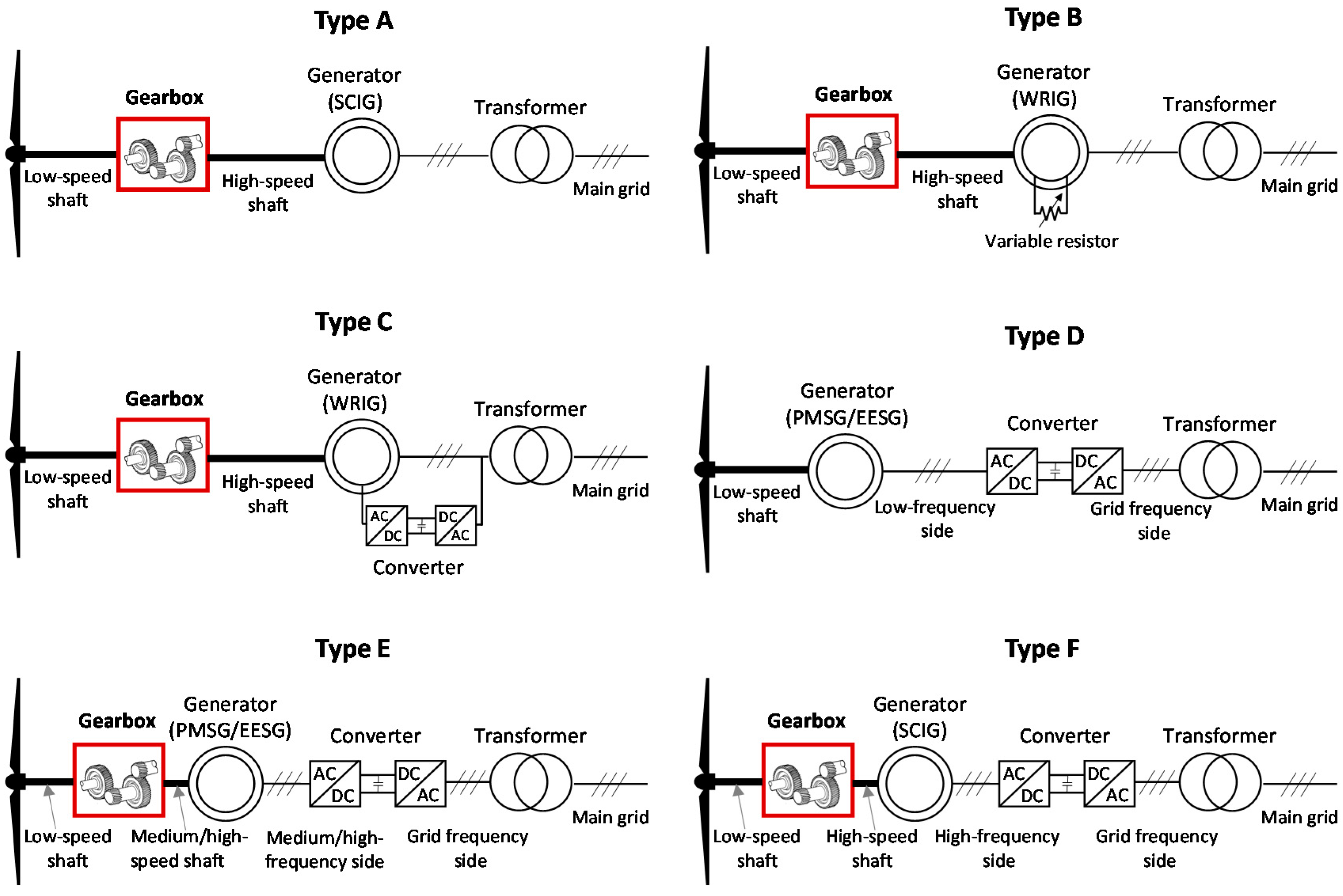
Figure 4.
Evolution of drive train configuration in onshore wind turbines by geographical zone (Source: JRC Wind Energy Database).
Figure 4.
Evolution of drive train configuration in onshore wind turbines by geographical zone (Source: JRC Wind Energy Database).
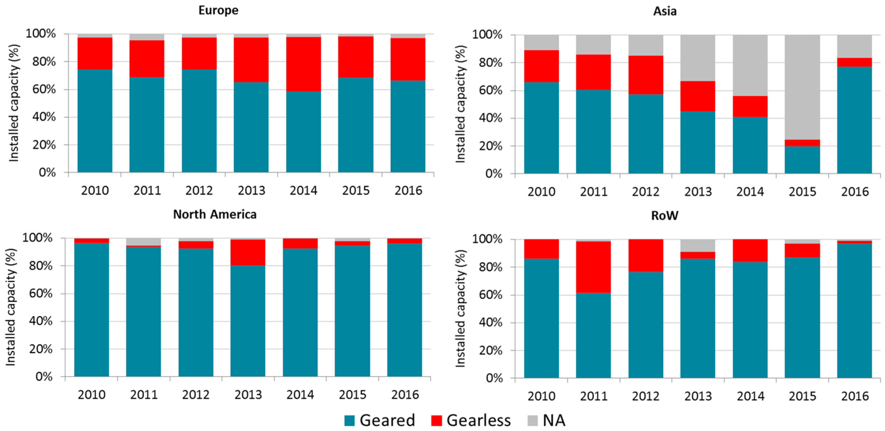
Figure 5.
Evolution of types of drive train configuration in onshore wind turbines by geographical zone (Source: JRC Wind Energy Database). “NA” represents Not Available records in the Joint Research Centre (JRC) Wind Energy Database.
Figure 5.
Evolution of types of drive train configuration in onshore wind turbines by geographical zone (Source: JRC Wind Energy Database). “NA” represents Not Available records in the Joint Research Centre (JRC) Wind Energy Database.

Figure 6.
Types of drive train configuration according to nominal power of onshore wind turbines installed in 2016 (Source: JRC Wind Energy Database). “NA” represents Not Available records in the JRC Wind Energy Database.
Figure 6.
Types of drive train configuration according to nominal power of onshore wind turbines installed in 2016 (Source: JRC Wind Energy Database). “NA” represents Not Available records in the JRC Wind Energy Database.

Figure 7.
Number of stages of gearboxes in geared drive train configurations. Data corresponds to cumulative capacity installed in the global onshore market by the end of 2016. (Source: JRC Wind Energy Database). “NA” represents Not Available records in the JRC Wind Energy Database.
Figure 7.
Number of stages of gearboxes in geared drive train configurations. Data corresponds to cumulative capacity installed in the global onshore market by the end of 2016. (Source: JRC Wind Energy Database). “NA” represents Not Available records in the JRC Wind Energy Database.
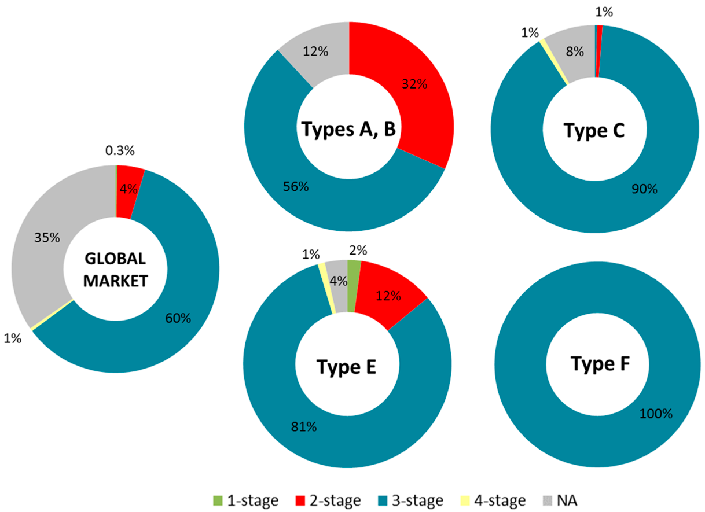
Figure 8.
Evolution of number of stages of gearboxes in geared drive train configurations in the global onshore market (Source: JRC Wind Energy Database). “NA” represents Not Available records in the JRC Wind Energy Database.
Figure 8.
Evolution of number of stages of gearboxes in geared drive train configurations in the global onshore market (Source: JRC Wind Energy Database). “NA” represents Not Available records in the JRC Wind Energy Database.
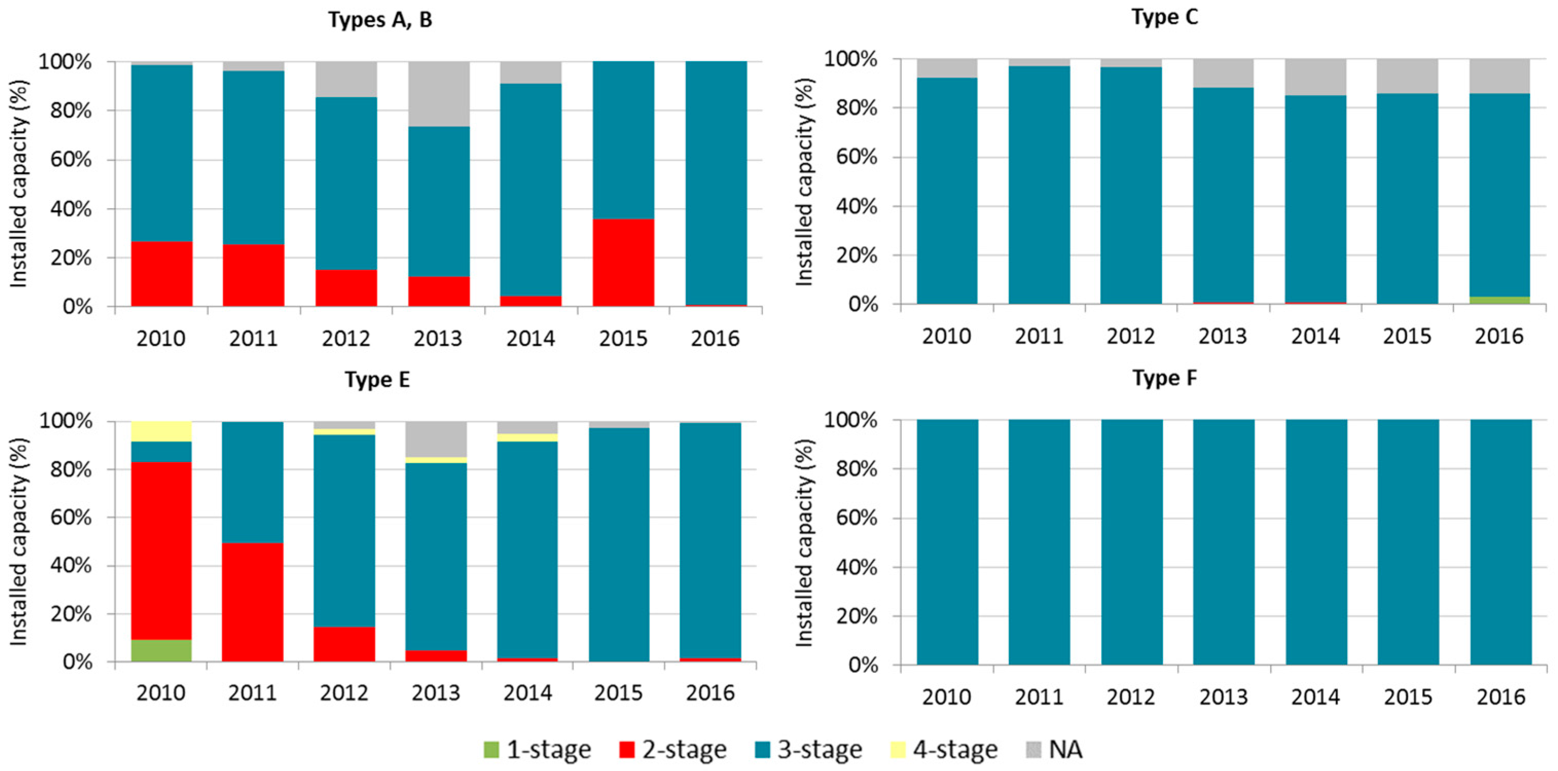
Figure 9.
Number of stages of the gearboxes in geared drive trains classified according to wind turbine nominal power. Data corresponds to cumulative capacity installed in the global onshore market by the end of 2016. (Source: JRC Wind Energy Database). “NA” represents Not Available records in the JRC Wind Energy Database.
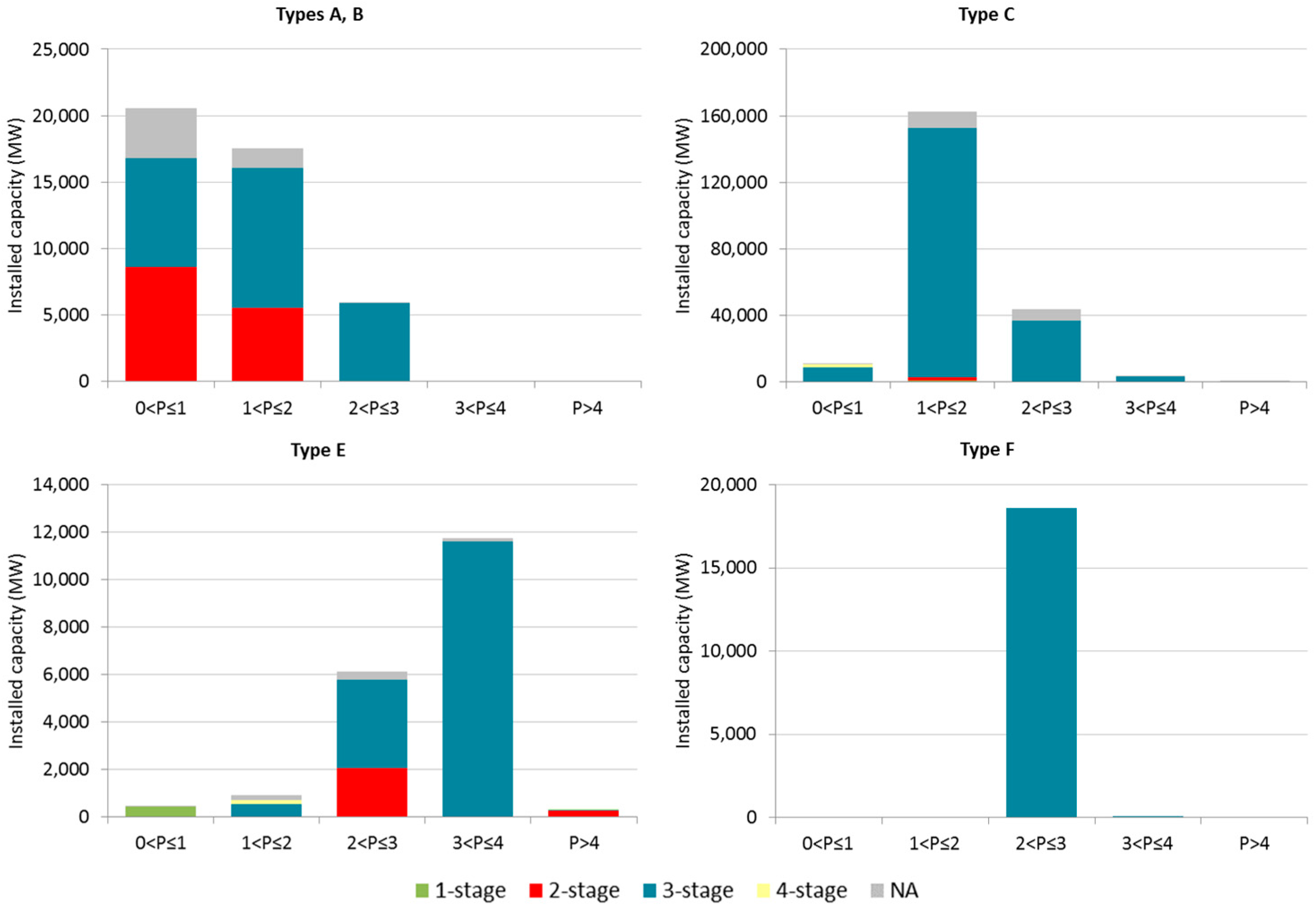
Figure 10.
Types of gears used in 3-stage gearboxes used in the different types of drive trains. Data corresponds to cumulative capacity installed in the global onshore market by the end of 2016. (Source: JRC Wind Energy Database). “NA” represents Not Available records in the JRC Wind Energy Database. Note: In the configurations planetary—helical and planetary—spur is not possible to identify if the number of planetary stages is either 1 or 2 as this information is not provided by the wind turbine manufacturer.

Figure 11.
Types of gears used in 3-stage gearboxes in the different types of drive trains sorted by wind turbine nominal power. Data corresponds to cumulative capacity installed in the global onshore market by the end of 2016. (Source: JRC Wind Energy Database). Note: Please see the note in Figure 10.

Figure 12.
Multiplication ratio in geared onshore wind turbines according to the number of stages. Data corresponds to cumulative capacity installed in the global onshore market by the end of 2016. (Source: JRC Wind Energy Database) (Due to the lack of publicly available data on the gearbox ratio of some wind turbine models, the results shown in Figure 12 and Figure 13 only comprise the 34% of the overall installed capacity over the period 2006–2016).
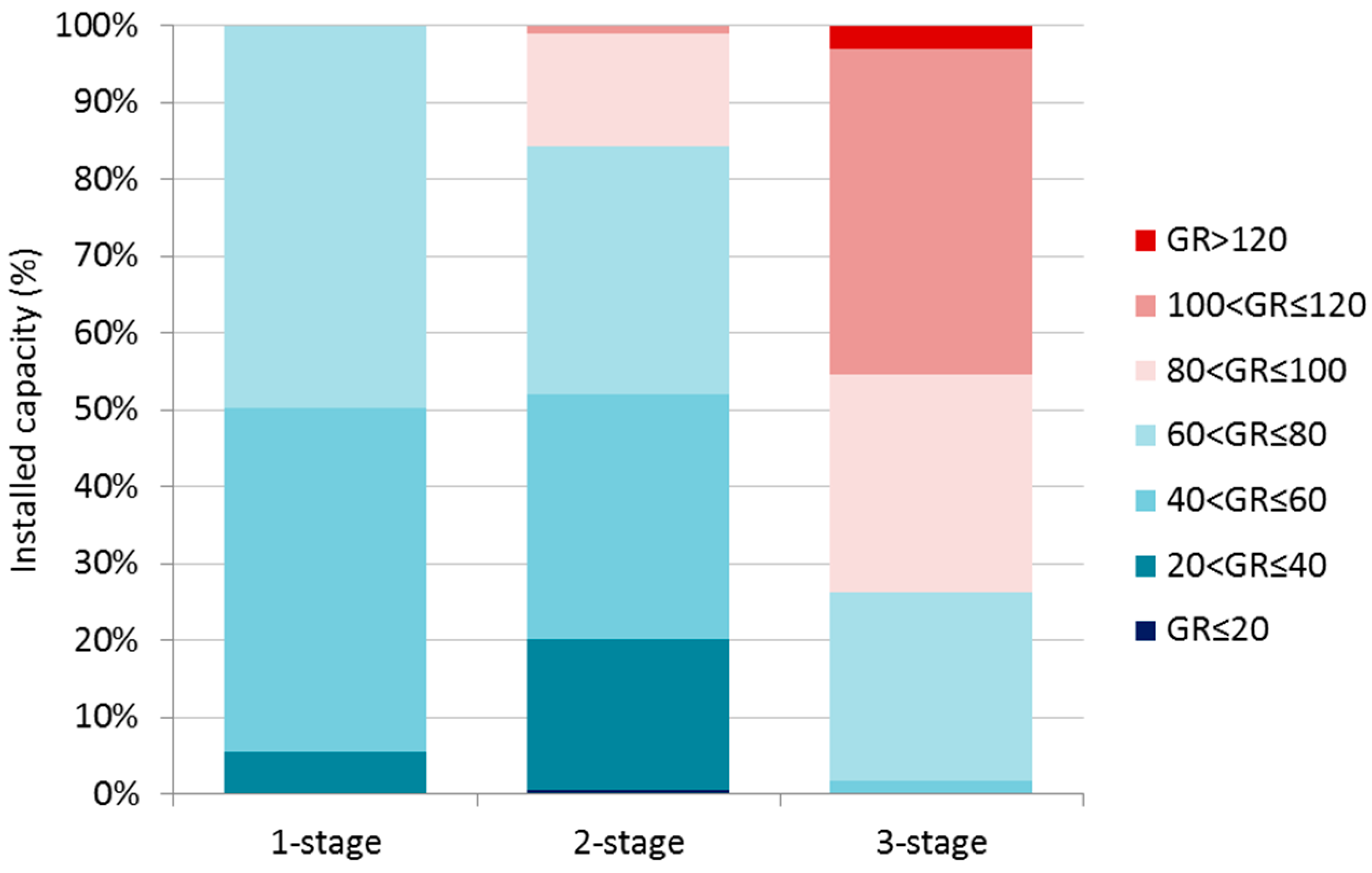
Figure 13.
Evolution of multiplication ratio of geared onshore wind turbines in the 10-year period between 2006 and 2016 (Source: JRC Wind Energy Database).
Figure 13.
Evolution of multiplication ratio of geared onshore wind turbines in the 10-year period between 2006 and 2016 (Source: JRC Wind Energy Database).

Table 1.
Main characteristics of the different types of gears used in wind turbines gearboxes [34].
Table 1.
Main characteristics of the different types of gears used in wind turbines gearboxes [34].
| Parallel Gears | Planetary Gears | |
|---|---|---|
| Spur | Helical | |
| (+) Better efficiency | (+) Silent operation | (+) Compact size |
| (+) Easy assembly | (+) Smooth behaviour | (+) Highest efficiency |
| (+) Large gear ratios | (+) Mechanical strength | (+) Low level of noise |
| (−) Noisy operation | (−) Axial reaction forces | (+/−) High torque/bearing load |
| (−) Only for low-speed | (−) Lower efficiency | (−) Complexity |
Note: (+) advantages, (−) disadvantages.
© 2017 by the authors. Licensee MDPI, Basel, Switzerland. This article is an open access article distributed under the terms and conditions of the Creative Commons Attribution (CC BY) license (http://creativecommons.org/licenses/by/4.0/).
Share and Cite
MDPI and ACS Style
Vázquez-Hernández, C.; Serrano-González, J.; Centeno, G. A Market-Based Analysis on the Main Characteristics of Gearboxes Used in Onshore Wind Turbines. Energies 2017, 10, 1686. https://doi.org/10.3390/en10111686
AMA Style
Vázquez-Hernández C, Serrano-González J, Centeno G. A Market-Based Analysis on the Main Characteristics of Gearboxes Used in Onshore Wind Turbines. Energies. 2017; 10(11):1686. https://doi.org/10.3390/en10111686
Chicago/Turabian StyleVázquez-Hernández, Cristina, Javier Serrano-González, and Gabriel Centeno. 2017. "A Market-Based Analysis on the Main Characteristics of Gearboxes Used in Onshore Wind Turbines" Energies 10, no. 11: 1686. https://doi.org/10.3390/en10111686
Note that from the first issue of 2016, this journal uses article numbers instead of page numbers. See further details here.