Article

Ideal Point Design and Operation of CO2-Based Transcritical Rankine Cycle (CTRC) System Based on High Utilization of Engine’s Waste Heats

State Key Laboratory of Engines, Tianjin University, 92 Weijin Road, Nankai District, Tianjin 300072, China
*
Author to whom correspondence should be addressed.
Energies 2017, 10(11), 1692; https://doi.org/10.3390/en10111692
Submission received: 28 September 2017 / Revised: 22 October 2017 / Accepted: 23 October 2017 / Published: 25 October 2017
(This article belongs to the Section F: Electrical Engineering)

Abstract

:
This research conducted a study specially to systematically analyze combined recovery of exhaust gas and engine coolant and related influence mechanism, including a detailed theoretical study and an assistant experimental study. In this research, CO2-based transcritical Rankine cycle (CTRC) was used for fully combining the wastes heats. The main objective of theoretical research was to search an ‘ideal point’ of the recovery system and related influence mechanism, which was defined as operating condition of complete recovery of two waste heats. The theoretical methodology of this study could also provide a design reference for effective combined recovery of two or multiple waste heats in other fields. Based on a kW-class preheated CTRC prototype that was designed by the ‘ideal point’ method, an experimental study was conducted to verify combined utilization degree of two engine waste heats by the CTRC system. The operating results showed that the prototype can gain 44.4–49.8 kW and 22.7–26.7 kW heat absorption from exhaust gas and engine coolant, respectively. To direct practical operation, an experimental optimization work on the operating process was conducted for complete recovery of engine coolant exactly, which avoided deficient or excessive recovery.

1. Introduction

Currently, engine waste heat recovery (E-WHR) is attracting increasing interest, which is an effective means to improve fuel utilization efficiency of engines. Among engine waste heats, exhaust gas and engine coolant are the main carriers. Exhaust gas is a high-grade waste heat source, which is generally regarded as the first recovery target. In Wang’s research on E-WHR, a diesel engine and a gasoline engine are selected as the recovery objects, whose exhaust temperature approaches over 700 °C and over 400 °C, respectively [1]. While, engine coolant is a relative low grade waste heat, whose temperature is below 100 °C, but still significant due to the comparative amount of waste heat [2]. Using a thermodynamic cycle to generate extra power is a high-efficiency way among the technologies of E-WHR, mainly including single-loop organic Rankine cycle (ORC) [3,4], dual-loop ORC [5,6], steam Rankine cycle [7,8], CO2-based transcritical Rankine cycle (CTRC). Moreover, thermodynamic cycle is a feasible scheme to make a combined recovery of exhaust gas and engine coolant. Engine coolant can be used as a preheating source based on the basic use of exhaust gas.
CTRC is a suitable technology used for E-WHR due to well environmental performance, small system size and stable chemical property in direct heat transfer with exhaust gas [9,10]. Compared with another general-used power cycle, ORC, the CTRC does not need intermediate systems and consists of only one heat exchanger for the evaporation process, which increases the system’s exergy efficiency [11]. Meanwhile, owning to the good flow and heat transfer properties of supercritical CO2, CTRC system has a superior heat transfer performance compared with ORCs [12,13], which can obtain smaller heat exchangers and make the plant more compact.
Both theoretical and experimental investigations on CTRC for E-WHR were performed in recent years. Theoretical researches mainly focus on the comparison and selection of the system configuration. Chen et al. [14] compared different CO2 bottoming systems for a vehicle engine, including a CTRC, a CO2 Brayton cycle and a CO2 combined power and cooling cycle. Their results indicated that the CTRC was more suitable than the others. Farzaneh-Gord et al. [15] compared four CTRC configurations and presented that the CTRC with a regenerator and preheater obtains the maximum net power output, and the CTRC with a regenerator achieves the highest thermal efficiency. Kim et al. [16] used a cascade cycle and split cycle to optimize CTRC performance, and the results showed that a split cycle was the better choice that can produce the highest power over a wide range of operating conditions. Shu et al. [17] proposed three configuration selection maps based on the best output performance (net power output), the best exergy performance (exergy efficiency) and the best economic performance (electricity production cost). They are used for scheme selection for the CTRC design and application based on different target needs and different operating conditions. Moreover, there are few experimental researches on the CTRC, and most testing research are not based on real engines. A CTRC supplier in American, Echogen Power Systems (EPS) company, provided the preliminary testing results of a 250 kW system, which showed the potential for the exhaust waste heat recovery in a temperature range of 200–540 °C [18,19]. But the heat source in the testing process used steam instead of exhaust gas. Pan et al. [20] conducted a test bench of CTRC with an oil heat source. Due to only 21.4% isentropic efficiency of piston type expander, the thermal efficiency of system is relative low about 5.0% with expansion inlet and outlet pressure of about 11 MPa and 4.6 MPa, respectively. After complete the research of selection maps [17], Shu’s group continued to test practical performance of corresponding CTRC configurations based on a small-scale CTRC bench [21], the results indicates that the CTRC with a preheater and regenerator can improved the engine efficiency from 39.4 to 41.4%.
While, the main focus of most researches on the CTRC is the system performance (e.g., power output, thermal efficiency), the utilization rate of waste heat is rarely regarded as a special subject but really significant. Higher utilization rate of exhaust gas and engine coolant mean more energy input for the CTRC, then following produce more power output. Moreover, higher utilization rate of engine coolant will make low coolant temperature flow into cooling system of engine, which can reduce cooling load of fan or cooling tower. For systems only with exhaust gas recovery, the outlet temperature of exhaust gas in gas heater determines utilization rate of exhaust gas, which depends on several factors mainly involving the cycle form (subcritical cycle or transcritical cycle), temperature difference of pinch point and acid dew point temperature of exhaust gas [22]. Due to low inlet temperature of working fluid in gas heater (<50 °C), outlet temperature of exhaust gas has no restriction of pinch point. Hence, complete use of exhaust gas can be obtained only requiring a certain mass flow of working fluid.
Compared with the systems only recovering exhaust gas, systems combining exhaust gas and engine coolant have a more complex influence mechanism of utilization rate for various type waste heats. Except for the respective factors, the combined capability of exhaust gas and engine coolant takes an important role for their recovery rate. Well combined capability makes both complete utilization of exhaust gas and engine coolant. Different fluid has different combined capability of exhaust gas and engine coolant, which only has scattered results in the previous researches. Vaja et al. [23] calculated the preheated ORCs with working fluids of Benzene, R11 and R134a, which achieve only 0.175, 0.242 and 0.579 utilization rate of engine coolant, based on good utilization of exhaust gas waste heat. It seems to be difficult to recovery waste heat effectively available from the engine coolant by ORCs. Kim et al. [24] compared different preheat regions of subcritical ORCs by engine coolant. The results showed that 40% waste heat of the engine coolant is used for preheating the liquid region of evaporation process. The utilization rate would increase to 90% if engine coolant was used to heat the two-phase of evaporation process, but required an extremely low turbine inlet temperature below 100 °C. While, system with or without preheating process by engine coolant had little effect on the utilization rate of exhaust gas, which was always high over 75%. Therefore, for most organic fluids, they cannot combine exhaust gas and engine coolant well, usually weak for engine coolant. Comparatively, the research on the combined capability of preheated CTRC is rarer. Farzaneh-Gord et al. [15] conducted the preheated CTRC but only cared the system performance. In an earlier literature by Kim et al. [25], results indicated that the CTRC has a significant performance improvement by combined low-temperature and high-temperature heat source. The CTRC seemed to own better combined capability of exhaust gas and engine coolant, but this has not been concretely introduced in these researches.
For fully combining recovery of exhaust gas and engine coolant, this research conducted a study on the CTRC system. Instead of traditional thermodynamic performance, the combined capability of these two waste heats and corresponding influence mechanism were the main focus of this research. The main research object was to find an “ideal point” of the recovery system, which was defined as operating condition of complete recovery of two waste heats. The analysis and discussion were conducted from the angle of physical property of fluid, and divided into three parts considering the CTRC with or without regenerator, system performance at ‘ideal point’ and comparison with other organic fluids. Finally, an experimental study was conducted to verify utilization degree of exhaust gas and engine coolant based on a kW-class preheated CTRC prototype, as well as an operation optimization for exact recovery of engine coolant.

2. System Description and Modeling

Figure 1 shows the system structure and t-s diagram of the CTRC with a preheater (P-CTRC). A gasoline engine is selected as recovery target in this study, whose rated operating parameters are listed in Table 1. Combined with basic use of high-grade exhaust gas (777 °C), the low-grade engine coolant (89.4 °C) is used as a preheat source. The main process of the P-CTRC includes: heating process (1-2-3), expanding process, condensing process (4-5) and pumping process (5-1). Each process is in a stable state and neglects heat loss and pressure drop in pipes. The other assumptions for the components are listed in Table 2 [14,17,26].
The property of exhaust gas is based on the mass fraction of compositions with 19.84% CO2, 8.26% H2O, and 71.49% N2 [1]. The acid dew point temperature of exhaust gas is 120 °C and set as the minimum temperature of exhaust gas during simulating process [23]. The engine coolant is assumed as pure water. To meet the requirement of suitable coolant temperature into engine jacket, the minimum temperature of engine coolant cannot be lower than 85.3 °C.
Calculation is based on the MATLAB (2010) software and REFPROP (9.0) software. The calculating equations are illustrated as following:
For the pump:
W p u m p = m f ( h 1 h 5 ) = m f ( h 1 s h 5 ) / η p u m p
where, the subscript “1s” means the exit state of pump after isentropic compression, and the subscript “f” represents CO2 fluid.
For preheater:
Q p r e h = m f ( h 2 h 1 ) = m c c p c ( t c , i n t c , o u t )
where, the subscript “c” represents engine coolant, the subscript “c,in” and “c,out” mean the inlet and outlet state of engine coolant in preheater, respectively.
For the gas heater:
Q g h = m g c p g ( t g , i n t g , o u t ) = m f ( h 3 h 2 )
where, the subscripts “g,in” and “g,out” represent the inlet and exit state of exhaust gas in gas heater, respectively.
For the turbine and generator:
P o w e r = m f ( h 3 h 4 ) η g e n = m f ( h 3 h 4 s ) η t u r b η g e n
where, the subscript “4s” means the exit state of turbine after isentropic expansion.
For the condenser:
Q c o n d = m f ( h 4 h 5 )
Net power output of the system is calculated as:
W n e t = P o w e r W p u m p
Total heat absorption of the system is calculated as:
Q t h a = Q g h + Q p r e h
Thermal efficiency of the system is calculated as:
η t h = W n e t Q t h a
The efficiency of turbine, pump and generator are listed in Table 2. During the calculation by the models above, how to calculate mass flow rate of CO2 (mf) is the key step for the all calculating process. After getting the mf, each state of CO2 are determined. Pinch Point Temperature Difference (PPTD) method is usually used for calculation of mf [22,23], which was ever used for previous calculation on transcritical cycle in our group [22]. Hence, two mass flow rates are got when the system has two complete recovery processes, represented as following:
m f , 1 = m c c p c ( t c , i n t c , o u t , l o w e s t ) ( h 2 h 1 )
m f , 2 = m g c p g ( t g , i n t g , o u t , l o w e s t ) ( h 3 h 2 )
where, the tc,out,lowest is the lowest outlet temperature of engine coolant and refers to the returned temperature of engine coolant, which is much higher than t1 without the restriction of PPTD; the tg,out,lowest is the lowest outlet temperature of exhaust gas. Therefore, mf,1 and mf,2 presents the maximum mf produced by utilization of exhaust gas and engine coolant, respectively. If mf,1 is equal to mf,2, this mass flow rate is just to satisfied complete utilization of both exhaust gas and engine coolant. Otherwise, choose the minimum one of mf,1 and mf,2 as final mass flow rate to satisfy complete utilization of one waste heat.
In this paper, utilization rate of waste heat is associated with the ratio between recovery energy from waste heat and the available energy of waste heat. The available energy of waste heat is not the energy versus to an environment state, but maximum energy at a feasible condition. For exhaust gas, complete utilization degree is defined as gas temperature reduces to acid dew point. For engine coolant, complete utilization degree is defined as coolant temperature reduces to returned temperature by the CTRC. Thus, utilization rate of exhaust gas and engine coolant are respectively defined as:
U g = m g c p g ( t g , i n t g , o u t ) m g c p g ( t g , i n t g , d e w )
U c = m c c p c ( t c , i n t c , o u t ) m c c p c ( t c , i n t c , r e t u r n e d )
where, tg,dew, and tc,returned mean the acid dew point temperature of exhaust gas and the engine coolant temperature back to engine.
Detailed calculation strategy is shown in Figure 2, which is illustrated by the block diagram, helping readers easily understand the calculation process.
Modeling verification of this study has been done in the previous study of the CTRC [17] conducted by our group, which used the same mathematical models and the same system layout.

3. Theoretical Results and Discussion

3.1. “Ideal Point” Analysis of CTRC

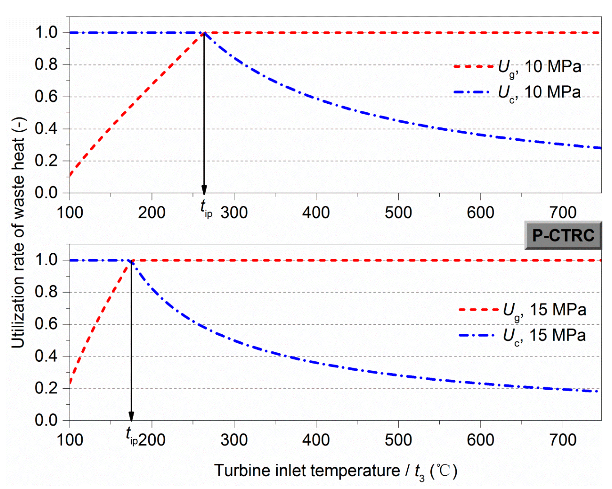
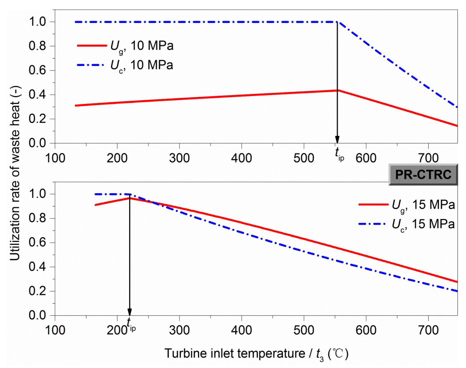
Figure 3 shows the variations of utilization rate of waste heats in the P-CTRC at P3 = 10 MPa and P3 = 15 MPa, red lines for the exhaust gas (Ug) and blue lines for the engine coolant (Uc). Ug increases then becomes 1 with an increase in t3, and Uc is 1 at low t3 then reduces with an increase in t3. It is because higher t3 needs more waste heat of exhaust gas, and more waste heat of engine coolant is utilized at the condition of lower t3.
A desired result appears in Figure 3 that, the change point of Uc from “1” to “not 1”, and the change point of Ug from “not 1” to “1”, occurs at the same t3. It means both complete recovery of exhaust gas and engine coolant will achieve when turbine inlet temperature operates at this t3. This research called it as “ideal point”, represented as tip, which means the ideal condition where both complete utilization of exhaust gas and engine coolant are obtained. The tip changes with the variation of turbine inlet pressure. The tip is 264 °C at P3 = 10 MPa, and 175 °C at P3 = 15 MPa.
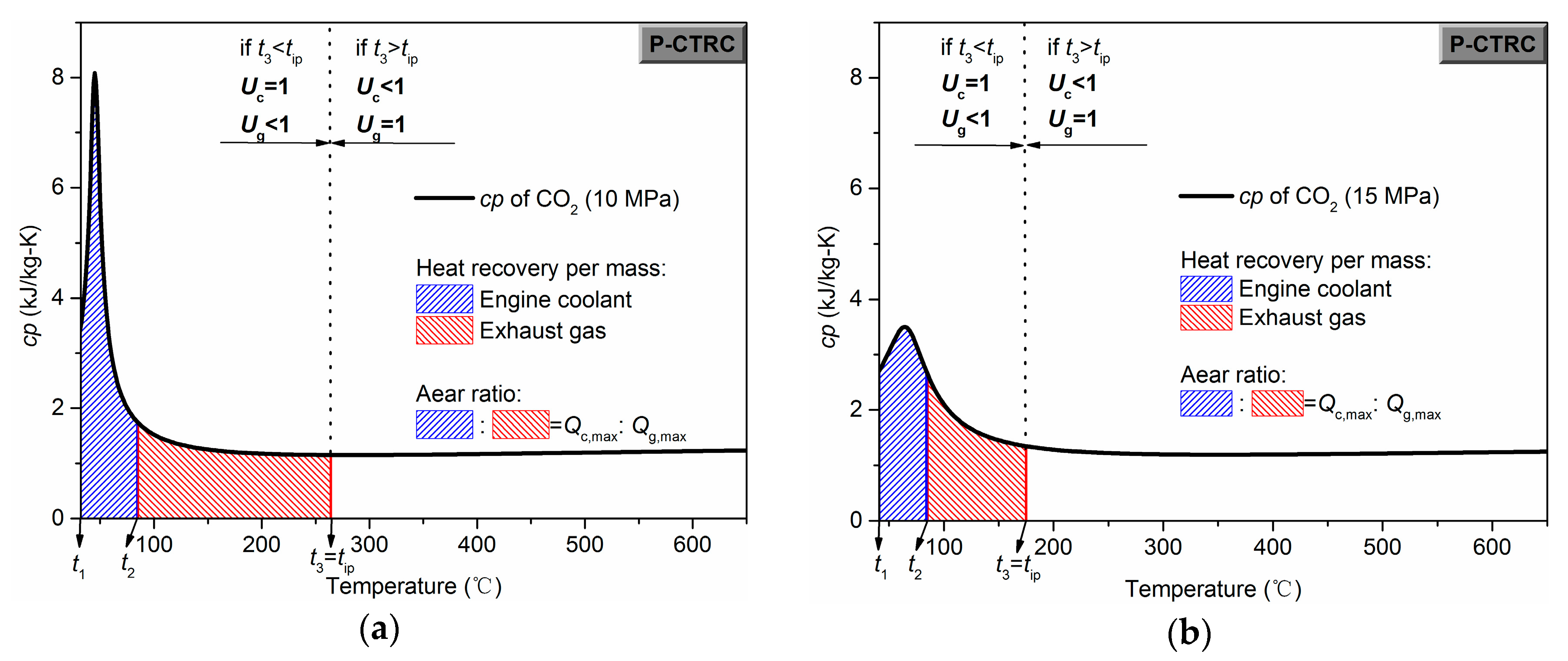
For introducing the producing mechanism of ‘ideal point’, the discussion about the CO2 combined capability between exhaust gas and engine coolant is required from the perspective of the CO2 property. As shown in Figure 4a,b, the bold black line means the cp change of CO2 with the CO2 temperature at pressure of 10 MPa and 15 MPa, respectively. The cp curves have a peak when the CO2 fluid is at supercritical pressure. The corresponding temperature is called the pseudo-critical temperature. The peak value of cp and corresponding pseudo-critical temperature changes with pressure. The cp peak value of 10 MPa is larger than that of 15 MPa, and the pseudo-critical temperature is lower. The enclosed area between the cp curve and X axis represents the 
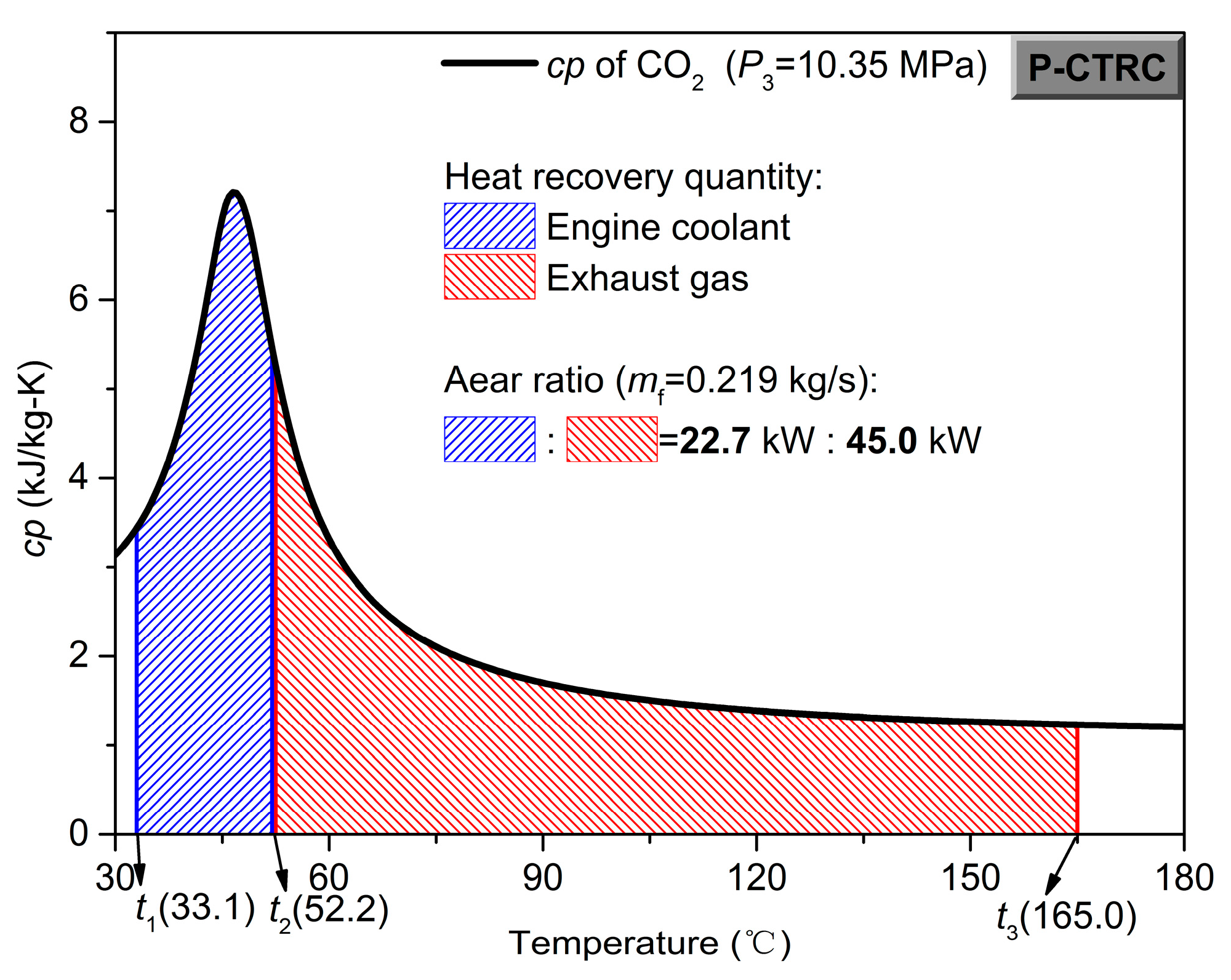
cp integration value with temperature, so its size represents the amount of heat absorption. In
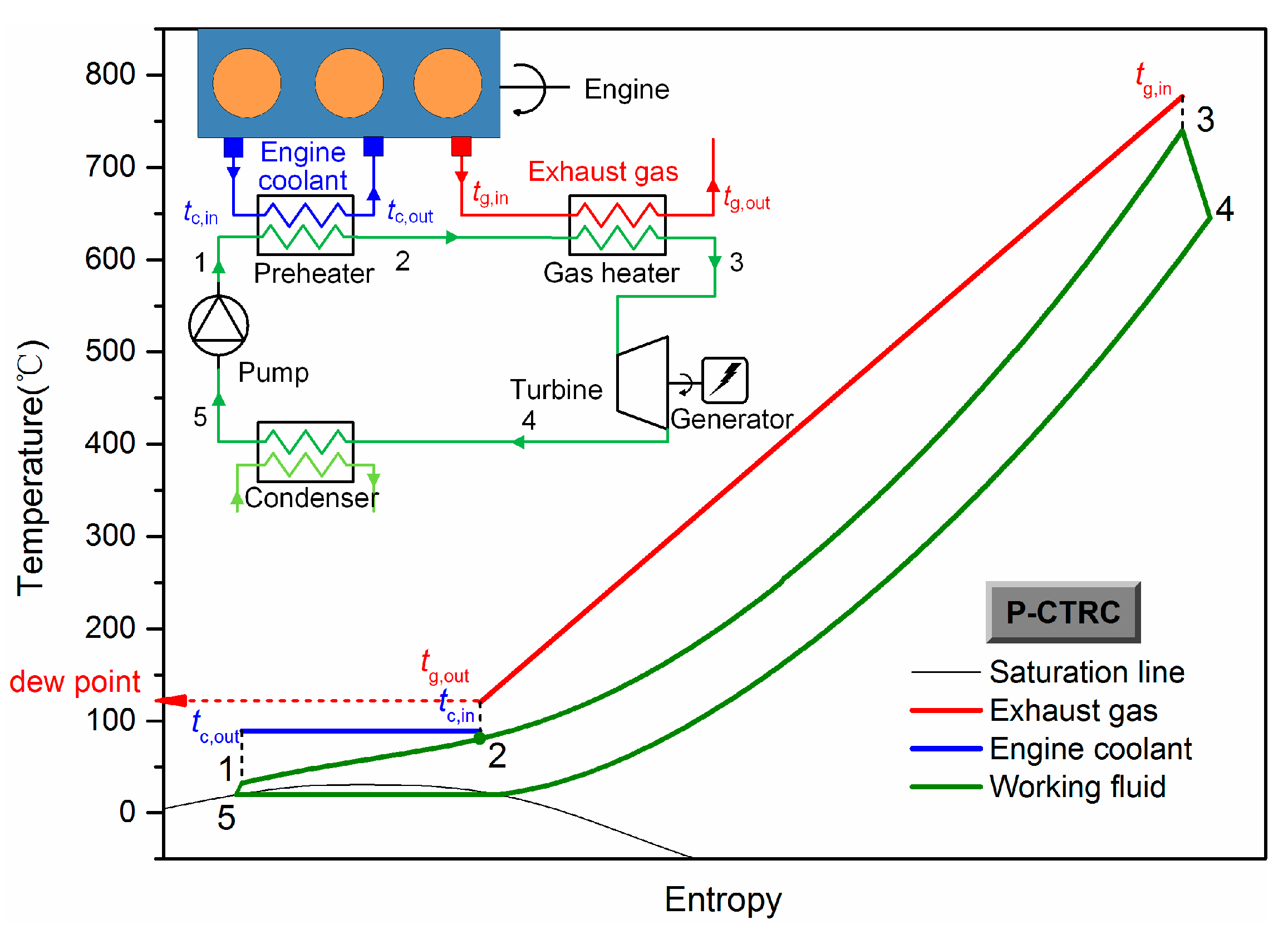
 Figure 4a,b, t1 and t2 (84.4 °C) respectively represent the inlet and outlet temperature of CO2 in the preheater So the blue area corresponds to heat recovery per mass from the engine coolant. And the temperature range at the right side of t2 is for the exhaust gas, the red area means the heat recovery per mass from the exhaust gas at the condition of t3 = tip. When the turbine inlet temperature is at the ‘ideal point’, the ratio between the blue and red area is just equal to the ratio between the maximum available energy of engine coolant and exhaust gas, which is called the ‘complete recovery ratio’. This means both complete recovery of exhaust gas and engine coolant can be achieved when meeting a suitable mass flow rate. If t3 is lower than tip, the engine coolant can get a complete use but the exhaust gas cannot, the blue area is bigger than the red area in this situation. The contrast performance occurs if t3 > tip. Therefore, it results in the special Ug and Uc performance of “ideal point”. When comparing the performance of 10 MPa and 15 MPa, it can be found that the smaller cp peak value of 15MPa causes smaller blue area relatively. Hence, the lower tip is required to meet the ratio between blue and red area equal to the complete recovery ratio. This is the reason why the tip of 15 MPa is lower than that of 10 MPa.
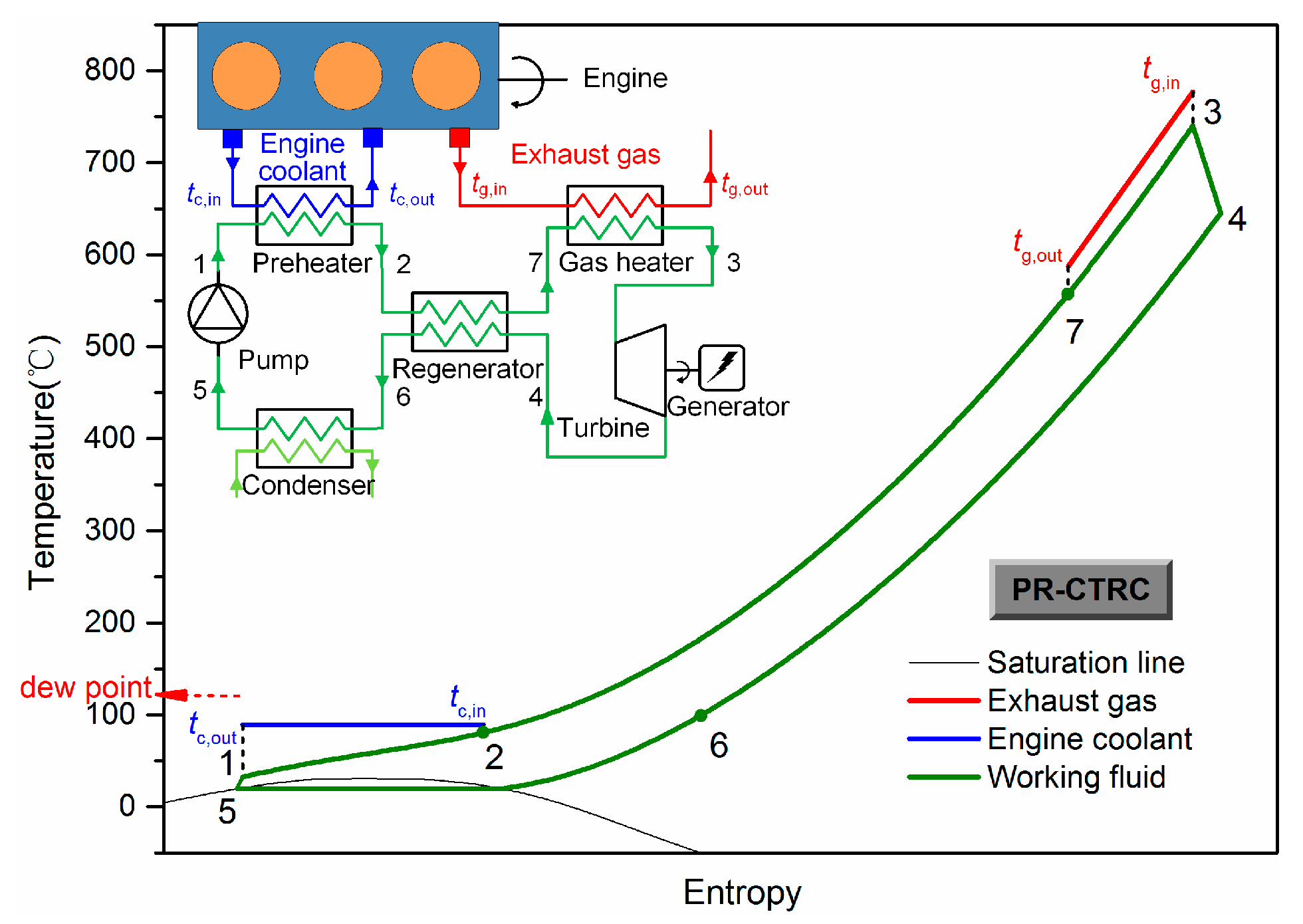
In the previous literatures about the CTRC, adding a regenerator is a usual method to improve the CTRC performance [27,
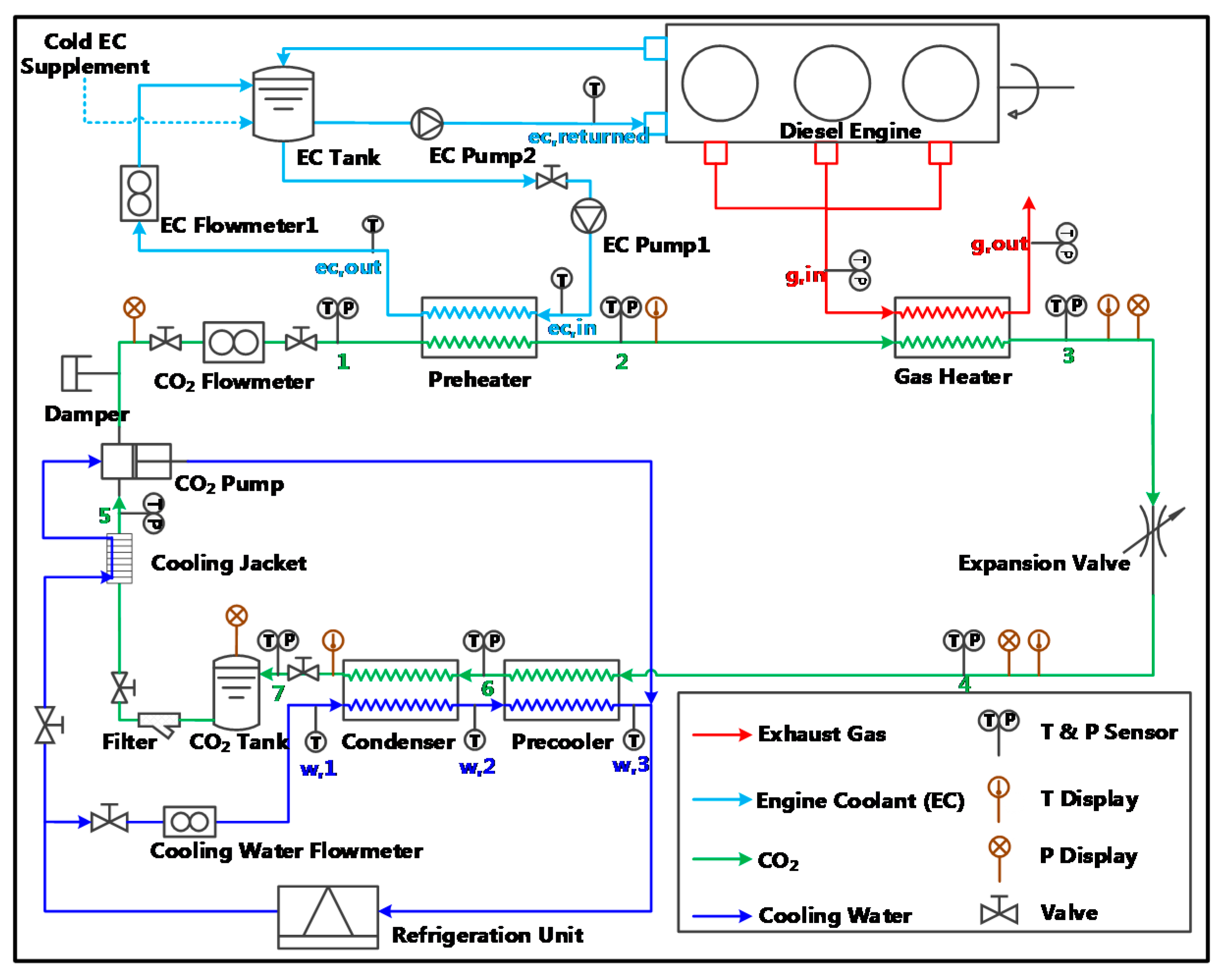
28]. Therefore, it is also significant to analyze the change of “ideal point” when adding a regenerator. The CTRC system with a preheater and a regenerator is called PR-CTRC in this paper, whose system structure and t-s diagram display in Figure 5. The fluid flows into the regenerator (2–7) after preheated in the preheater and is heated by turbine outlet fluid (4–6). Then it flows into the gas heater. It is essential to conduct an analysis considering the effect of regenerator, as the regenerator has impact on the combined recovery of exhaust gas and engine coolant. The number of heating process become three when adding a regenerator, which is two previously. In this paper, the temperature difference of pinch point is set to 15 °C, and occurs between the state 2 and 6. When t4t2 ≤ 15 °C, it means no regenerated condition for the system.
Figure 6 presents the utilization rate of waste heats in the PR-CTRC. The exhaust gas doesn’t obtain a complete use after adding the regenerator, in which the regenerated heat recovers a part of application temperature range of exhaust gas. But a peak value of Ug (Ug,max) occurs simultaneously with Uec changing from “1” to “not 1”. Thus, “ideal point” is also used for the PR-CTRC to represent the maximum recovery of exhaust gas and complete recovery of engine coolant. The tip of the PR-CTRC is 556 °C at P3 = 10 MPa, and 220 °C at P3 = 15 MPa.
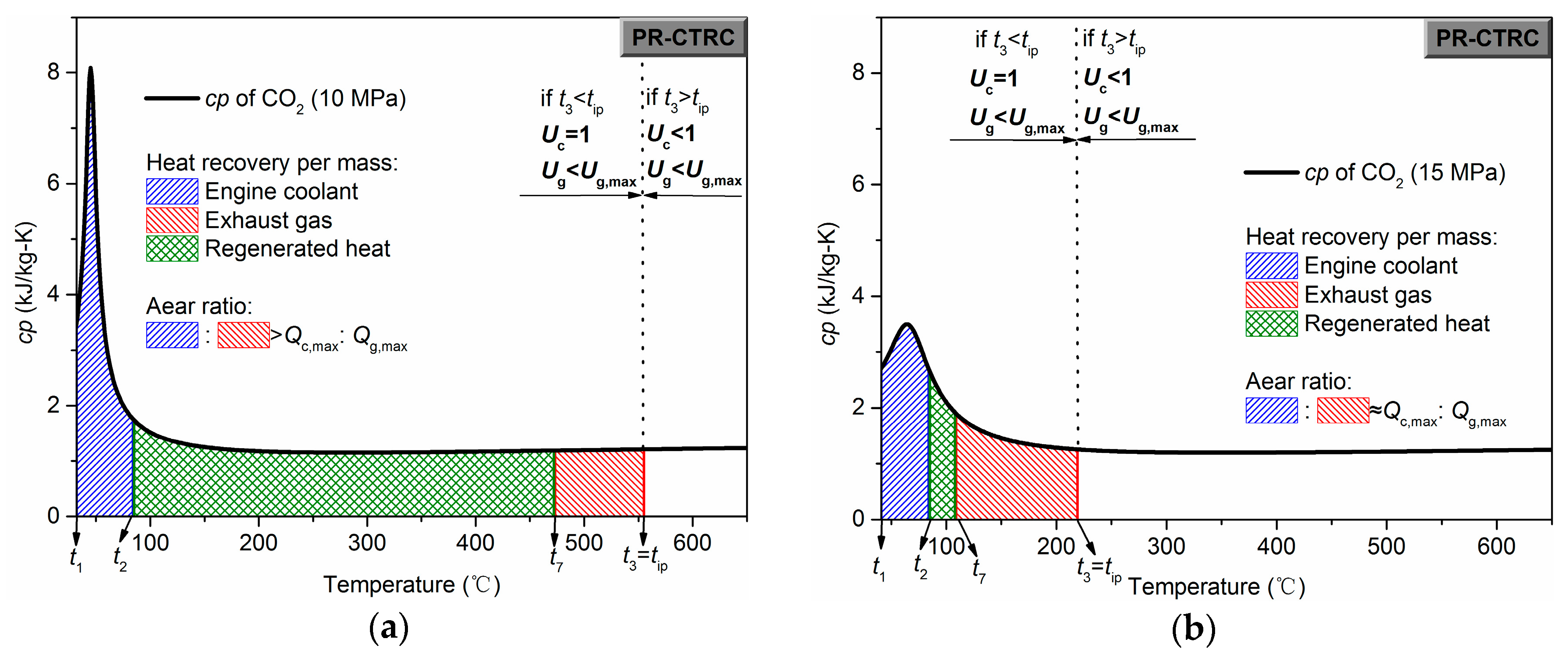
Therefore, the heating process in the regenerator is added to cp figure, shown as the green area in Figure 7a,b. Similarly, these two figures show the heat absorption capacity of working fluids at the “ideal point” of the PR-CTRC. As shown in Figure 7a, due to a low pressure ratio when P3 is 10 MPa, a high turbine outlet temperature is produced, further causing a large temperature range of the regenerated process in the regenerator. This results in that the ratio between the blue and red area is far less than the “complete recovery ratio”. Hence, the Ug,max at P3 = 10 MPa is 0.42, much less than 1. Differently, when P3 is 15 MPa, regenerated heat has little impact on the application temperature range of exhaust gas. The ratio between the blue and red area is still close to the “complete recovery ratio” (Figure 7b), following causes a high Ug,max (0.97). Therefore, from the perspective of sufficient use of energy, the PR-CTRC is suitable operating at the “ideal point” of 15 MPa versus to that of 10 MPa.

3.2. System Performance at “Ideal Point”

Although high utilization rate of exhaust gas and engine coolant are beneficial, output and efficiency performance are still the main pursue in a recovery system. Whether the best performance could be obtained at the “ideal point” is a worth studying. Therefore, performance of net power output (Wnet) and thermal efficiency (ηth) are taken into account in this section, as well as two important parameters, mass flow rate (mf) and total heat absorption (Qtha).
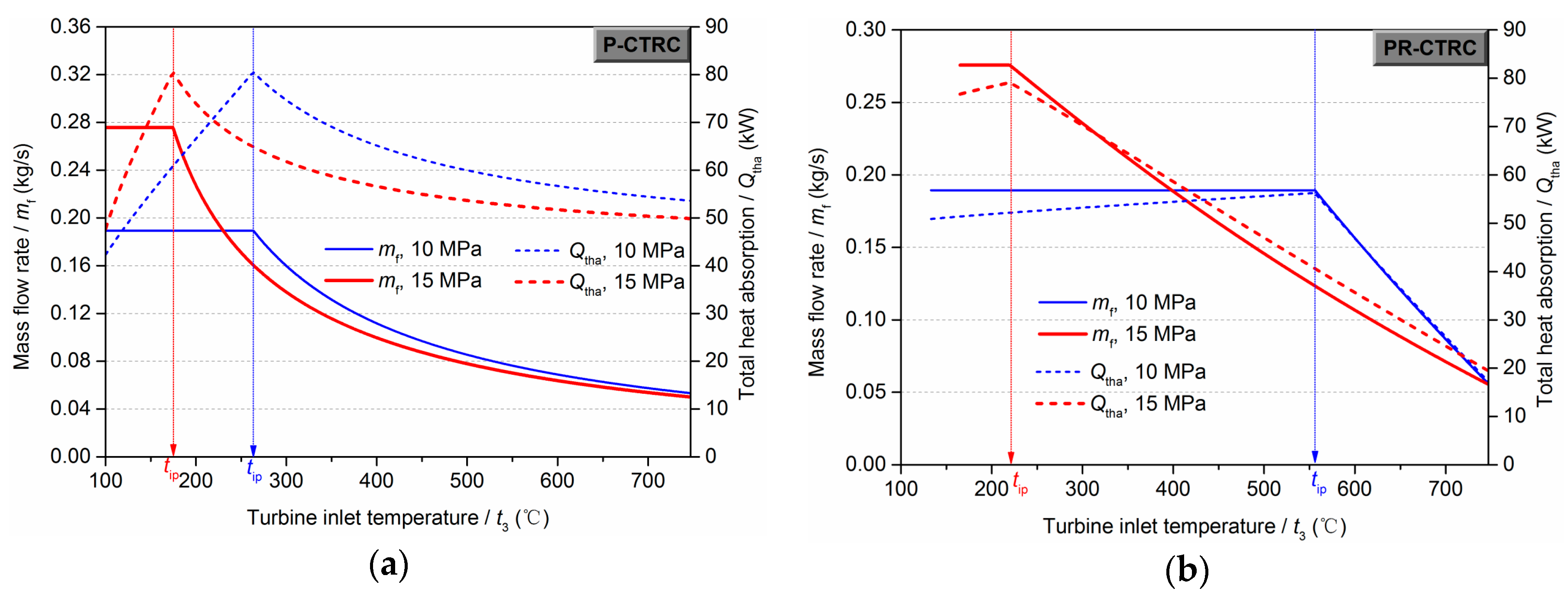
The mass flow rate variation trend with t3 is shown in Figure 8. As shown in the mathematics models (Equations (9) and (10)), the mass flow rate is obtained by the comparison between the complete utilization of exhaust gas and engine coolant, respectively. Hence, the mf is determined as a constant value by the constant energy of engine coolant at low t3 in the P-CTRC. At high t3 region, the mf decreases with an increase in outlet temperature of fluid (t3). Therefore, there is a transition point in the mass flow rate variation line that corresponding to the “ideal point”. Figure 8 also shows the variation of total heat absorption. Maximum total heat absorption is achieved at the “ideal point”. This is because “ideal point” means the highest Ug and Uc, following producing maximum energy input.
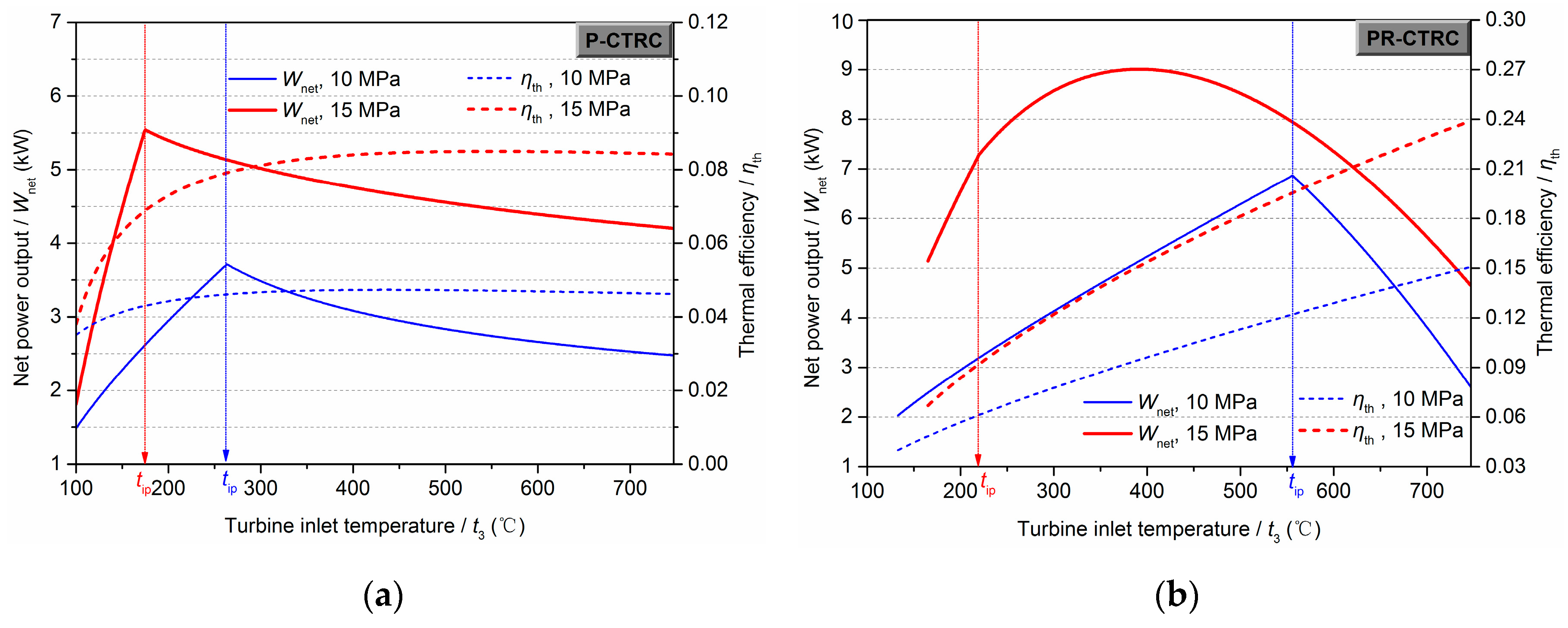
Although the “ideal point” has maximum mass flow rate and total heat absorption, it does not mean the maximum net power output as shown in Figure 9. There is a peak value existing in the variation line of net power output for the P-CTRC and the PR-CTRC. The corresponding turbine inlet temperature at the peak is identical with tip for the P-CTRC at 10, 15 MPa (Figure 9a) and the PR-CTRC at 10 MPa (Figure 9b). But for the PR-CTRC at 15 MPa (Figure 9b), the net power output variation trend only has change of increase rate and does not represent the maximum net power output. With a tighter connection with turbine inlet temperature, the highest thermal efficiency appears at high turbine inlet temperature range as expected, which has no link to the “ideal point”.
The analysis discussed above focuses on the performance of ‘ideal point’ at a certain turbine inlet pressure. A discussion on various performance of ‘ideal point’ at various turbine inlet pressures is conducted following.
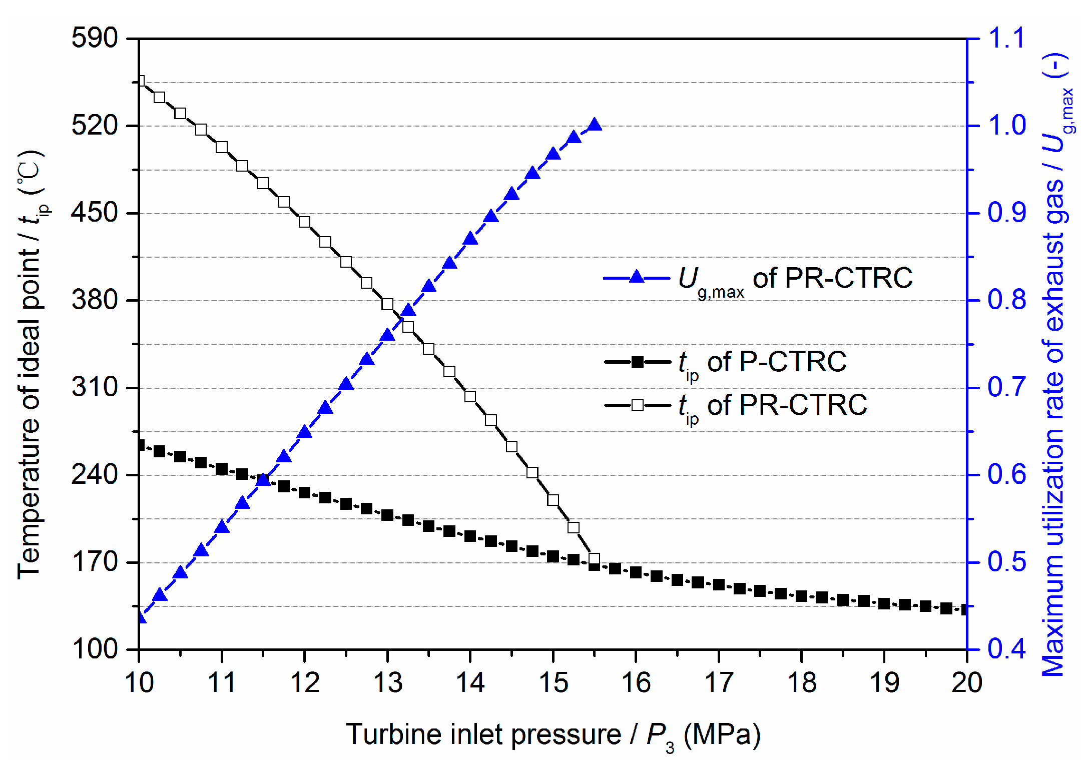
After calculating under the P3 from 10 MPa to 20 MPa, the tip of the P-CTRC and the PR-CTRC at each pressure is presented in Figure 10. The rule of searching for tip is based on the definition in Section 3.1. With an increase in P3, the tip of the P-CTRC decreases, as well as 
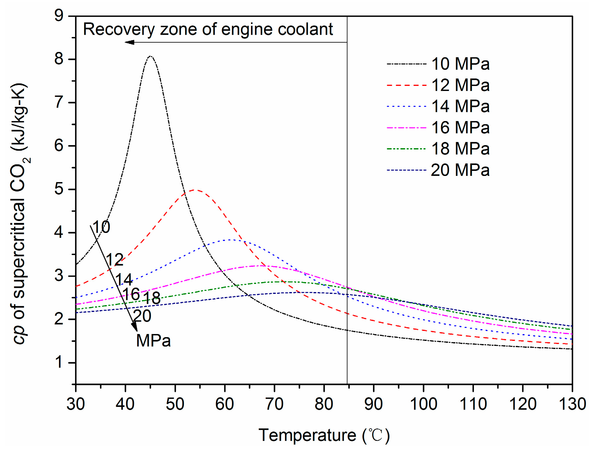
tip of the PR-CTRC. The reason from the CO2 property is that the peak value of cp decreases with an increase in P3, and the pseudo-critical temperature increases and drifts away from the recovery region of engine coolant, as shown in Figure 11. With an additional heating process, the tip of PR-CTRC is obviously higher than that of the P-CTRC at the same P3.
For the PR-CTRC, there exists a maximum turbine inlet pressure, no tip occurs above it. The maximum turbine inlet pressure is 15.5 MPa in this study. With an increase in P3, the temperature difference between the turbine inlet and outlet becomes larger, which reduces the regenerated degree of turbine outlet fluid. When the P3 is higher than the maximum value, there is no regenerated condition for the PR-CTRC. At this situation, the PR-CTRC can be considered as the P-CTRC actually. Hence, the end of tip for the PR-CTRC in Figure 10 approaches to the variation line of the P-CTRC. Different with the P-CTRC obtaining complete recovery of exhaust gas at tip, the PR-CTRC has a maximum utilization rate of exhaust gas (Ug,max), as shown in Figure 10. The Ug,max increases with an increase in P3, then approaches to 1 at the maximum P3 of each system, whose principle is similar to the discussion of tip. It indicates that both complete recovery of exhaust gas and engine coolant cannot achieve in the PR-CTRC, which only occurs in the P-CTRC.
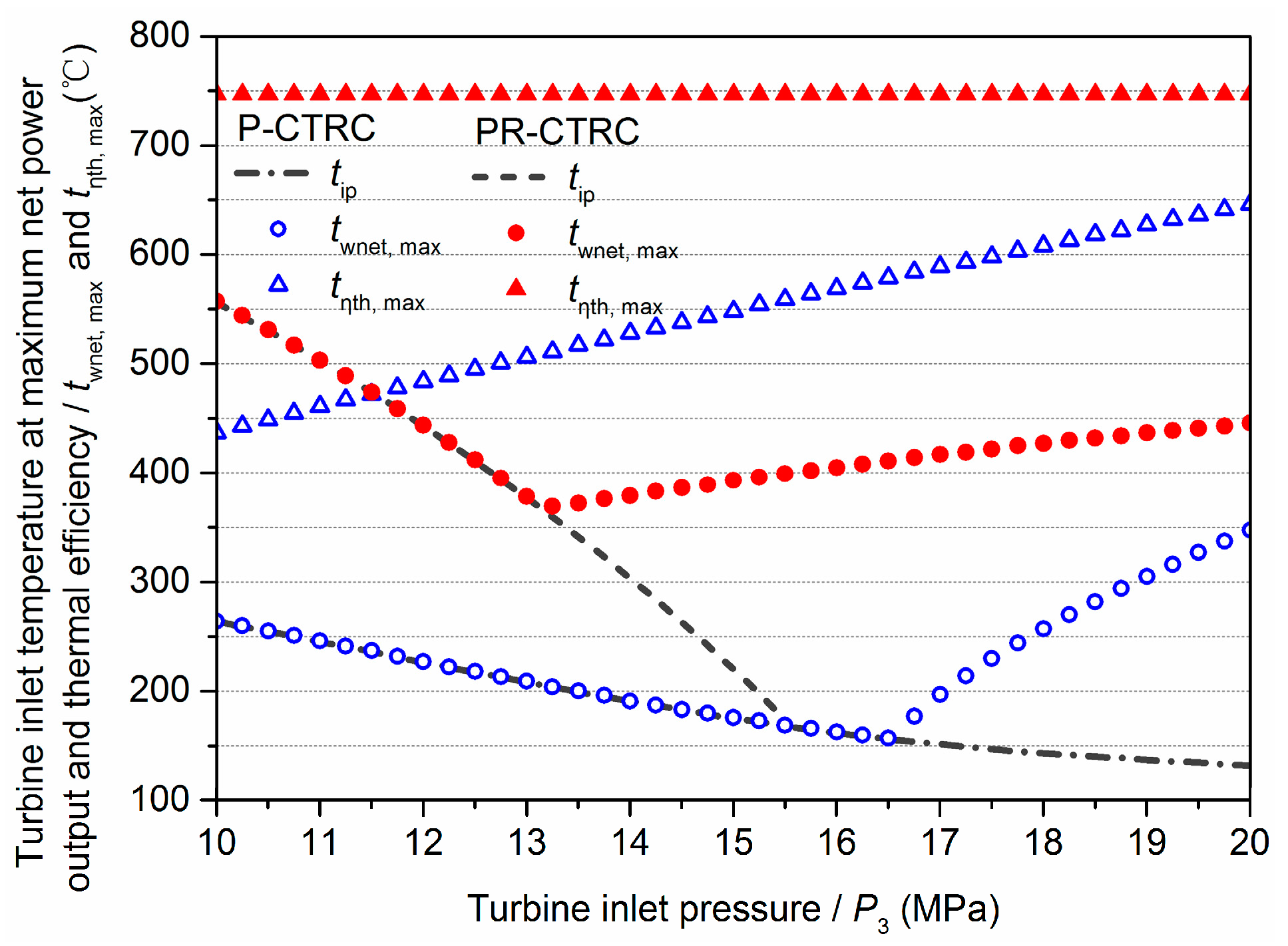
As a comparison with tip, the turbine inlet temperature at each P3 where can get maximum net power output (twnet,max) and thermal efficiency (tη,max) is shown in Figure 12. The twnet,max is equal to the tip firstly with an increase in turbine inlet pressure, then goes through a transition point and be different with tip. The transition pressure for the P-CTRC and the PR-CTRC is the 16.5 and 13.0 MPa, respectively. Different with the twnet,max and tip, the tη,max remains high value, especially for the PR-CTRC always being the highest turbine inlet temperature (747 °C). Therefore, a consequence we can get from these performance laws is that maximum net power output can be also obtained when system design at the ‘ideal point’ of low pressure range (<13 MPa for the P-CTRC, <16.5 MPa for the PR-CTRC). While, parameters selection would be considerable at high pressure range. The tip, twnet,max and tη,max are at low, mid and high turbine inlet temperature range. As an example, when the P-CTRC at 20 MPa, tip, twnet,max and tη,max is 132, 347, 646 °C. Decision to select turbine inlet temperature depends on the system tending to the “ideal point” or the maximum net power output or the highest thermal efficiency.

3.3. “Ideal Point” Comparison between CO2 and Organic Fluids

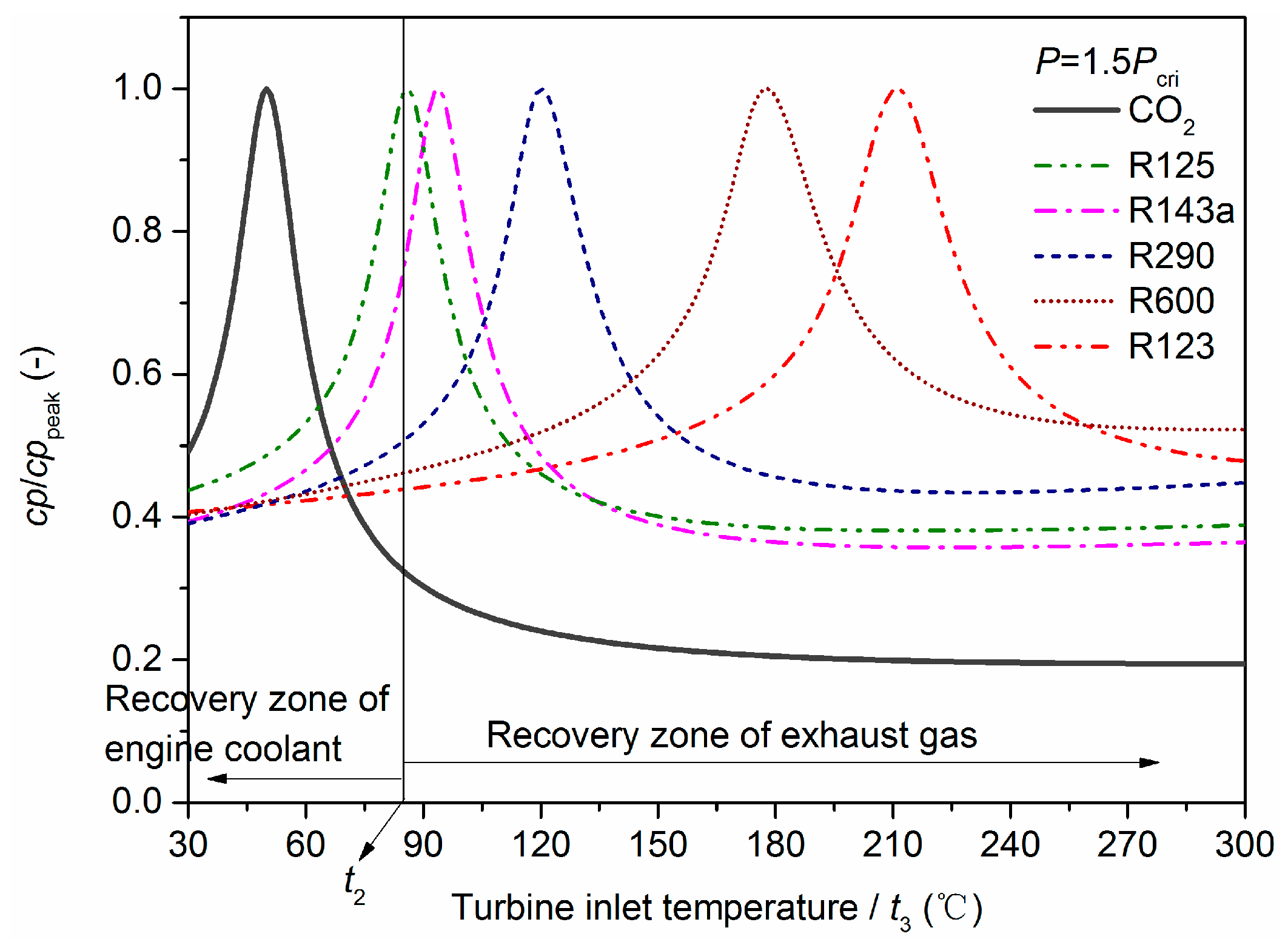
For clearer explanation of CO2 owning well combined capability of exhaust gas and engine coolant, comparison study with organic fluids is conducted.
The application temperature range of engine coolant is narrower than that of exhaust gas, but the energy of engine coolant is approximate equivalent to that of exhaust gas (Qc,max/Qg,max = 0.870). Therefore, higher cp is required in the application temperature range of engine coolant than that of exhaust gas if systems aim to realize complete utilization of exhaust gas and engine coolant meanwhile. It is obvious to find that the cp peak of supercritical CO2 is just located in the application temperature range of engine coolant. The cp property of the supercritical CO2 exactly owns better combined condition for exhaust gas and engine coolant. Just as shown in Figure 13, the values of cp/cppeak of CO2 and some frequently-used organic fluids (R125, R143a, R290, R600 and R123) at 1.5 times critical pressure. Only the cp peak of CO2 is located in the application temperature range of engine coolant. On the contrary, most organic fluids has a slight change of cp under normal pressure, or owns a peak value of cp under supercritical pressure but located at higher application temperature range than that of engine coolant. This is the reason why the organic fluids is inefficient to utilize the engine coolant but enough for exhaust gas.
Based on the transcritical Rankine cycle with a preheater, Table 3 lists the investigated fluids with critical parameters, utilization rate of waste heats, and temperature of idea point at 1.5 times critical pressure. It is easy to find that the pseudo-critical temperature has significant effect on the tip. With a higher critical temperature, the tip is lower or inexistent. With a low critical temperature of 31.0 °C, the tip is 244 °C for the CO2 system. And for the R600 and R123 with a high critical temperature of 152.0 and 183.7 °C, respectively, the tip of them are inexistent. The tip of R143a and R290 are close to the critical temperature, which is difficult to operate at the tip condition as expansion process is easy turn into two phase region for these two wet working fluids. Moreover, higher tip entering into the turbine makes more power output at the same condition. Therefore, CO2 with low critical temperature and higher tip is more suitable for the combined recovery of exhaust gas and engine coolant. As shown the results of t3 = 300 °C, system with organic fluids can obtain a complete recovery of exhaust gas (Ug = 1), but a lower utilization rate of engine coolant (Uc = 0.227–0.325) than CO2-based system (Uc = 0.763). Therefore, as a comparison with references [23,24] using organic fluids as working fluids, using CO2 has large advantage of utilization rate of engine coolant.
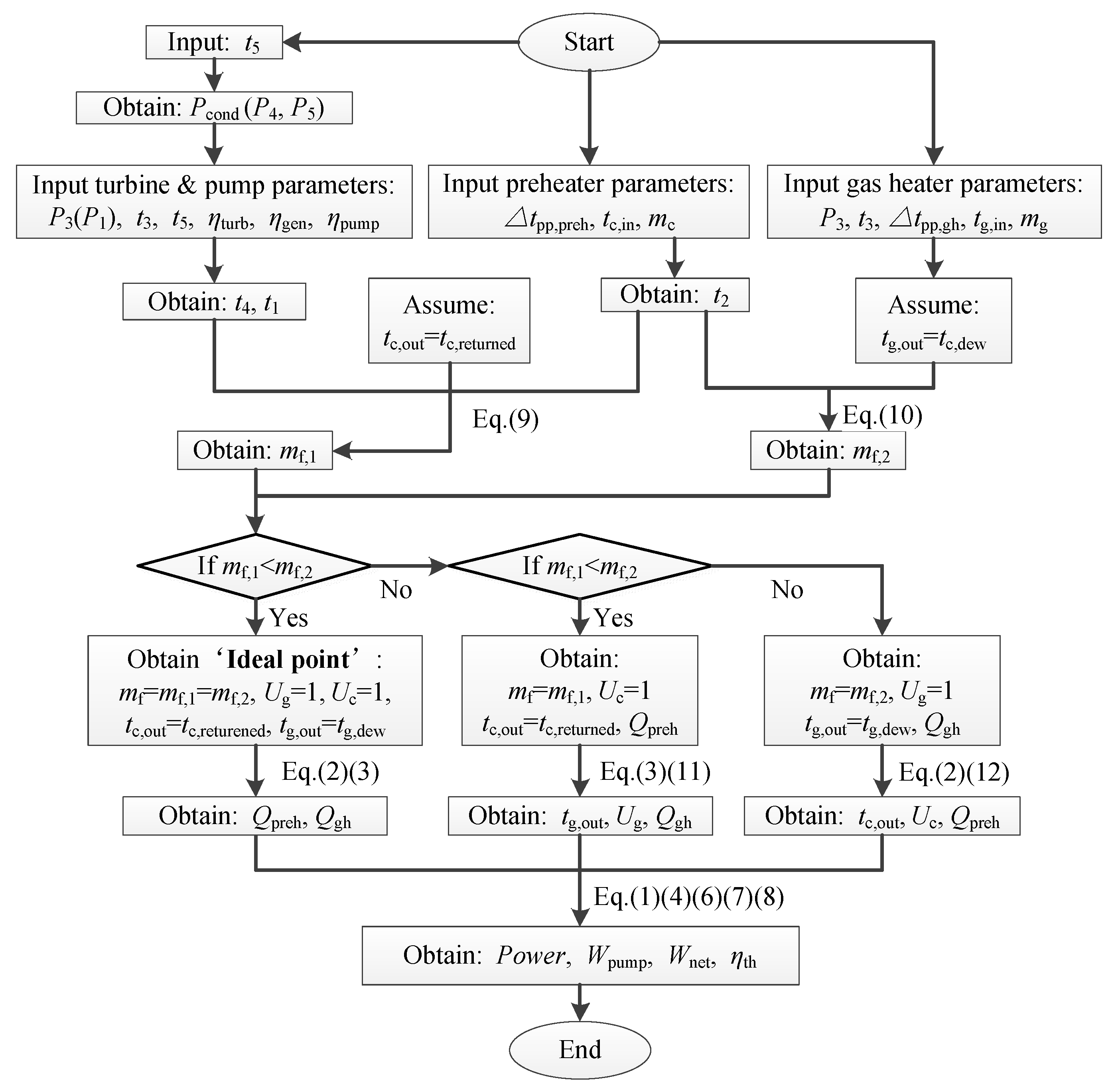
From the comparison study, it should be interesting to conduct a fast way to obtain the “ideal point” of any kind of fluids. Such a method should be more convenient to engineering design. Therefore, this study proposes a prediction formula of turbine inlet temperature at the condition of “ideal point”. From the analysis and calculation models above, the turbine inlet temperature at the condition of “ideal point” (tip) mainly depends on quantity and quality of exhaust gas and engine coolant, turbine inlet pressure, inlet and outlet parameter of fluid in preheater, and inlet parameter of fluid in gas heater, which is described as following:
t i p = t ( P i p , h i p ) ,   h i p = m g C p g ( t g , i n t g , o u t ) m c C p c ( t c , i n t c , r e t u r n e d ) ( h p r e h , o u t h p r e h , i n ) + h g h , i n
Wherein,
h p r e h , o u t = h ( P i p , t p r e h , o u t ) , t p r e h , o u t = t c , i n + Δ t p p , g h ;
h p r e h , i n = h ( P i p , t p r e h , i n ) , t p r e h , i n = t p u m p , o u t ;
h g h , i n = h ( P i p , t g h , i n ) ,   t g h , i n = t p r e h , o u t ( P - CTRC ) ,   t g h , i n = t r e g , o u t ( PR - CTRC ) ;
t g , o u t = t g , d e w   when   t g , d e w > t g h , i n + Δ t p p , g h ;
t g , o u t = t g h , i n + Δ t p p   when   t g , d e w t g h , i n + Δ t p p , g h ;
Among them, t i = t ( P i , h i ) and h i = h ( P i , t i ) are the processes of gaining property of working fluid, which can be realized by REFPROP 9.0 software.
The tip can be rapidly and simply obtained by this prediction formula, which is used as a direction for engineering design when utilizing exhaust gas and engine coolant simultaneously, and also as a methodology used for combined recovery of two or multiple waste heats in other fields.

4. Performance of P-CTRC Prototype

Based on the “ideal point” design method, a kW-class P-CTRC prototype was conducted to investigate the practical utilization degree of exhaust gas and engine coolant. An optimization work on the practical operating of the P-CTRC loop was conducted for exact recovery of engine coolant, which avoided deficient or excessive recovery.

4.1. Description of the P-CTRC Prototype

The P-CTRC prototype was constructed specially for E-WHR, whose practical layout is shown in Figure 14 and diagram is shown in Figure 15. The main components and measuring devices are listed in Table 4. As the turbine was not available and under design, an expansion valve was adopted temporarily instead of it to provide high and low pressures of the prototype.
A diesel engine was temporarily used to provide waste heat condition of exhaust gas and engine coolant. Main parameters of the diesel engine are listed in Table 5, which is the bigger scale than the gasoline engine. Hence, the diesel engine operated at part load to match the small-scale P-CTRC system. The engine coolant used water as working fluid, and was driven by the engine coolant pump2 (EC pump2). An open EC tank was set for heat rejection of hot water with a large evaporation area when the engine didn’t link to the P-CTRC. But the heat rejection capacity of EC tank was not generally enough, then a cold EC supplement system was additionally used to mix some cold water to maintain the thermal balance. In this system, the coolant flow did not go through the preheater straightly. Instead of it, a part of flow driven by the EC pump1 was introduced to preheat CO2 from the EC tank. The scheme of two EC pump is convenient and suitable for controlling the engine-CTRC combined system at laboratory conditions. Hence, the recovery for the engine coolant by the preheater can replace additional cold EC supplement system.

4.2. Verification for Sufficient Recovery of Exhaust Gas and Engine Coolant

After operating the engine at a fixed condition, the CO2 pump at a constant speed, the EC pump1 at a constant speed, and by adjusting various opening of the expansion valve, a group results with various high pressures (P3) ranging from 7.57 MPa to 10.35 MPa were tested and shown in Table 6.
The exhaust gas with inlet temperature of 480.1–482.9 °C is utilized in gas heater and reaches to outlet temperature of 71.1–83.1 °C, which means the full recovery of it and even excessive recovery due to the limitation of 120 °C. In addition to part of heat dissipation to the environment on the large surface of the gas heater, the CO2 gains 44.4–49.8 kW heat absorption in the gas heater. For the engine coolant, the flow with inlet temperature of 75.1–75.7 °C is utilized in preheater and cooled down to outlet temperature of 28.5–33.8 °C, which nearly approaches to the inlet temperature of CO2. Hence, the engine coolant was also utilized fully by the CO2 that gets 22.7–26.7 kW heat absorption in preheater. Therefore, the P-CTRC proves to own the capability for sufficient recovery of exhaust gas and engine coolant. As the gas heater has large surface contacting environment, and larger mass flow rate of exhaust gas (diesel engine) through the exchanger than that of design (gasoline engine), heat transfer effectiveness of the gas heater is 73.7–80.2%, which needs to be improved in the future. But for the preheater, well thermal match and compact exchanger type produces higher effectiveness, almost above 90%.
Similar with the analysis in Section 3.1, this process in cp perspective using condition 5 as an example is shown in Figure 16. The CO2 absorbs 22.7 kW heat from the engine coolant in the preheater with a temperature increase from 33.1 °C to 52.2 °C, and absorbs 45.0 kW heat from the exhaust gas in the gas heater with a temperature increase from 52.2 °C to 165.0 °C. It is obvious to find that heat recovery zone of engine coolant locates around the critical area, and benefits the peak of cp peak of supercritical CO2. In the preheater, CO2 temperature only gets 29.1 °C increase, but large amount of heat absorption is obtained. Therefore, it proves that the waste heat recovery of engine coolant with characteristic of low-grade but large-amount can be accomplished by the P-CTRC in a narrow temperature range. On this basis, it still does not affect the full recovery of exhaust gas.
η i = Q i Q i , m a x ,   Q g h , m a x = m g c p g ( t g , i n t 2 ) ,   Q p r e h , m a x = m c c p c ( t c , i n t 1 )

4.3. Operation Optimization

In practical operation, a problem should be considered that exhaust gas and engine coolant may not achieve complete recovery exactly, and deficient and excessive recovery may happen. As shown in Table 6, system operates from condition 1 to condition 5 sequentially, then the tec,returned increased from 83.9 to 84.7 °C. If operation still continued afterwards, the tec,returned should reaches up to the boiling temperature of engine coolant. This conditions are considered as the deficient recovery of engine coolant, which means inadequate heat dissipation of engine coolant and makes tec,returned increase continuously. The tec,returned is a significant parameter for the engine operation, too high causes boiling problem of engine coolant, too low leads to low-efficiency operating of engine. In this study, an optimization was conducted to find the optimal recovery condition of engine coolant.
The diesel engine also operated at constant condition: 50% of rated speed (1100 rpm) and 50% load (601 N·m). The theoretical work in Section 3 was to find ideal turbine inlet temperature and corresponding mass flow rate of CO2 to match complete recovery of the waste heats. But in this study, adjusting CO2 flow would obviously influent the high pressure of system, thus another strategy was adopted from the perspective of engine coolant side. The flow rate of engine coolant into the preheater could be adjusted by frequency changer of EC pump1. The final objective was to find an optimal frequency, namely an optimal mass flow rate of engine coolant that made the tec,returned stable. But change of tec,returned is not obvious in a short time, so the tec,in is selected as the observation object to replace the tec,returned. Because the tec,in will increase and decrease when the tec,returned increases and decreases correspondingly. Therefore, if tec,in keeps stable at the experiment time, it means thermal balance of engine coolant system is constructed and achieve a complete recovery of engine coolant. If tec,in keeps increasing, it means the preheater is unable to undertake enough heat rejection and make temperature increasing, which calls deficient recovery of engine coolant in this study. On the contrary, if tec,in keeps decreasing it means excessive recovery of engine coolant. It should be note that, there is difference between the tec,back and the tec,in relating to the heat loss on the long pipe between the EC tank and the P-CTRC system.
By a previous work, a rough frequency range of EC pump1 was selected and finally operated at 8.00, 8.33, 8.75, 9.17, 9.50 Hz. High frequency means more flow of engine coolant into the preheater. The CO2 pump operated at a constant speed (80 rpm) and expansion valve was at a fixed opening for the five groups. For convenient observation, temperature change of tec,in versus starting time was selected as the target, which means 0 °C temperature change is the optimal. The starting and ending temperatures at the five groups are listed at Table 7.
As shown in Figure 17, the results of temperature change at 120 s were obtained for five frequencies. The region of above and under 0 °C means the deficient and excessive recovery, respectively. From 8.00 Hz to 9.50 Hz, the flow rate of engine coolant increases, thus engine coolant crosses from deficient recovery to excessive recovery. When EC pump1 operates at 8.00 Hz, lacking engine coolant flows into the preheater and leads to deficient recovery, then makes tec,in has an increasing change of about 0.8 °C in 120 s. And for the 9.50 Hz, overmuch engine coolant flows into the preheater and leads to excessive recovery, then makes tec,in has about an decreasing change of 0.7 °C in 120 s. 8.75 Hz is optimal frequency among the five, and temperature change controls less than 0.1 °C. With necessary heat rejection of engine coolant on the pipe and EC tank under laboratory conditions, this optimal condition can be considered as the complete recovery condition of engine coolant. As shown in Table 7, the tec,back also indicates the same change performance but a smaller change than the tec,in, so the discussion of tec,in is effective.

5. Conclusions

A detailed theoretical study of the CTRC system was conducted for analyzing complete recovery of exhaust gas and engine coolant, as well as a simple test study. Main conclusions can be listed as follows:
  • For the P-CTRC, the ‘ideal point’ is defined as an important reference to the combined capability of exhaust gas and engine coolant, which represents the condition of both complete recovery of two waste heats and is expressed by tip. The tip changes with the variation of turbine inlet pressure. The tip is 264 °C at P3 = 10 MPa. The ‘ideal point’ also exists in the PR-CTRC, but has some difference with that of the P-CTRC. The exhaust gas doesn’t obtain a complete use after adding the regenerator, in which the regenerated heat recovers a part of application temperature range of exhaust gas and increases the tip. The tip is 556 °C at P3 = 10 MPa. There exists a maximum turbine inlet pressure (15.5 MPa) for the PR-CTRC, no tip occurs above it.
  • Maximum net power output can be also obtained when system design at the ‘ideal point’ of low pressure range (<13 MPa for the P-CTRC, <16.5 MPa for the PR-CTRC). While, there is no link between the ‘ideal point’ and the highest thermal efficiency. Parameters selection will be considerable at high pressure range, Decision to select turbine inlet temperature depends on the system tending to the “ideal point” or the maximum net power output or the highest thermal efficiency.
  • This study proposes a prediction formula of tip, which is used as a direction for engineering design for utilizing exhaust gas and engine coolant meanwhile, and also as a methodology used for combined recovery of two or multiple waste heats in other fields.
  • The operating results with P3 range of 7.57–10.35 MPa show that sufficient recovery of the two waste heats can be achieve by the P-CTRC prototype. The exhaust gas with initial temperature of 480.1–482.9 °C is utilized to 71.1–83.1 °C, and the engine coolant with initial temperature of 75.1–75.7 °C is utilized to 28.5–33.8 °C. The CO2 gains 44.4–49.8 kW and 22.7–26.7 kW heat absorption from the exhaust gas engine coolant respectively. Heat transfer effectiveness of the gas heater and the preheater are 73.7–80.2% and 89.8–96.1%, respectively.
  • An experimental optimization is conducted to search the optimal operating condition of achieving complete recovery of engine coolant exactly, and avoid deficient and excessive recovery. After operating five different frequencies of EC pump1, an optimal amount of engine coolant flowing into the preheater was found, and the corresponding optimal frequency of EC pump1 is 8.75 Hz.

Acknowledgments

The authors would like to acknowledge the National Natural Science Foundation of China (No. 51636005 and No. 51676133) for grants and supports.

Author Contributions

All authors have worked on this manuscript together and all authors have read and approved the final manuscript. Lingfeng Shi, Gequn Shu, and Hua Tian conceived and designed the experiments; Lingfeng Shi, Liwen Chang and Guangdai Huang performed the experiments; Tianyu Chen and Xiaoya Li analyzed the data; Lingfeng Shi wrote the paper.

Conflicts of Interest

The authors declare no conflict of interest.

Abbreviations

condcondenser
cengine coolant
dewacid dew point
fworking fluid
gexhaust gas
gengenerator
ghgas heater
ieach component
ipideal point
ininlet
maxmaximum
outoutlet
pppinch point
prehpreheater
regregenerator
ththermal
thatotal heat absorption
turbturbine
wcooling water
EC/ecengine coolant
1-7state point
1s, 4sstate points for the ideal case
ηefficiency
cpspecific heat capacity (kJ/(kg∙K))
hspecific enthalpy (kJ/kg)
mmass flow rate (kg/s)
Ppressure (kPa)
Powerelectricity power (kW)
Qheat flow rate (kW)
ttemperature (°C)
Δtpp,ghtemperature difference (°C)
Uutilization rate of waste heat
Wwork (kW)
CTRCCO2-based transcritical Rankine cycle
E-WHRengine waste heat recovery
ORCorganic Rankine cycle
P-CTRCCO2-based transcritical Rankine cycle with a preheater
PR-CTRCCO2-based transcritical Rankine cycle with a preheater and a regenerator
PPTDPinch Point Temperature Difference

References

  1. Wang, T.; Zhang, Y.; Zhang, J.; Peng, Z.; Shu, G. Comparisons of system benefits and thermo-economics for exhaust energy recovery applied on a heavy-duty diesel engine and a light-duty vehicle gasoline engine. Energy Convers. Manag. 2014, 84, 97–107. [Google Scholar] [CrossRef]
  2. Fu, J.; Liu, J.; Feng, R.; Yang, Y.; Wang, L.; Wang, Y. Energy and exergy analysis on gasoline engine based on mapping characteristics experiment. Appl. Energy 2013, 102, 622–630. [Google Scholar] [CrossRef]
  3. Song, S.; Zhang, H.; Zhao, R.; Meng, F.; Liu, H.; Wang, J.; Yang, B. Simulation and Performance Analysis of Organic Rankine Systems for Stationary Compressed Natural Gas Engine. Energies 2017, 10, 544. [Google Scholar] [CrossRef]
  4. Benato, A.; Macor, A. Biogas Engine Waste Heat Recovery Using Organic Rankine Cycle. Energies 2017, 10, 327. [Google Scholar] [CrossRef]
  5. Yao, B.; Yang, F.; Zhang, H.; Wang, E.; Yang, K. Analyzing the performance of a dual loop organic rankine cycle system for waste heat recovery of a heavy-duty compressed natural gas engine. Energies 2014, 7, 7794–7815. [Google Scholar] [CrossRef]
  6. Wang, X.; Tian, H.; Shu, G. Part-Load Performance Prediction and Operation Strategy Design of Organic Rankine Cycles with a Medium Cycle Used for Recovering Waste Heat from Gaseous Fuel Engines. Energies 2016, 9, 527. [Google Scholar] [CrossRef]
  7. Altosole, M.; Benvenuto, G.; Campora, U.; Laviola, M.; Trucco, A. Waste heat recovery from marine gas turbines and diesel engines. Energies 2017, 10, 718. [Google Scholar] [CrossRef]
  8. Andreasen, J.; Meroni, A.; Haglind, F. A Comparison of Organic and Steam Rankine Cycle Power Systems for Waste Heat Recovery on Large Ships. Energies 2017, 10, 547. [Google Scholar] [CrossRef]
  9. Cardemil, J.M.; Silva, A.K.D. Parametrized overview of CO2, power cycles for different operation conditions and configurations—An absolute and relative performance analysis. Appl. Therm. Eng. 2016, 100, 146–154. [Google Scholar] [CrossRef]
  10. Sarkar, J. Review and future trends of supercritical CO2, Rankine cycle for low-grade heat conversion. Renew. Sustain. Energy Rev. 2015, 48, 434–451. [Google Scholar] [CrossRef]
  11. Wang, X.; Dai, Y. Exergoeconomic analysis of utilizing the transcritical CO2 cycle and the ORC for a recompression supercritical CO2 cycle waste heat recovery: A comparative study. Appl. Energy 2016, 170, 193–207. [Google Scholar] [CrossRef]
  12. Guo, T.; Wang, H.; Zhang, S. Comparative analysis of CO2-based transcritical Rankine cycle and HFC245fa-based subcritical organic Rankine cycle using low-temperature geothermal source. Sci. China Technol. Sci. 2010, 53, 1638–1646. [Google Scholar] [CrossRef]
  13. Cayer, E.; Galanis, N.; Nesreddine, H. Parametric study and optimization of a transcritical power cycle using a low temperature source. Appl. Energy 2010, 87, 1349–1357. [Google Scholar] [CrossRef]
  14. Chen, Y.; Lundqvist, P.; Platell, P. Theoretical research of carbon dioxide power cycle application in automobile industry to reduce vehicle’s fuel consumption. Appl. Therm. Eng. 2005, 25, 2041–2053. [Google Scholar] [CrossRef]
  15. Farzaneh-Gord, M.; Mirmohammadi, A.S.; Behi, M.; Yahyaie, A. Heat recovery from a natural gas powered internal combustion engine by CO2 transcritical power cycle. Therm. Sci. 2010, 14, 897–911. [Google Scholar] [CrossRef]
  16. Kim, Y.; Sohn, J.; Yoon, E. Supercritical CO2, Rankine cycles for waste heat recovery from gas turbine. Energy 2017, 118, 893–905. [Google Scholar] [CrossRef]
  17. Shu, G.; Shi, L.; Tian, H.; Deng, S.; Li, X.; Chang, L. Configurations selection maps of CO2-based transcritical Rankine cycle (CTRC) for thermal energy management of engine waste heat. Appl. Energy 2017, 186, 423–435. [Google Scholar] [CrossRef]
  18. Persichilli, M.; Held, T.; Hostler, S.; Zdankiewicz, E.; Klapp, D. Transforming Waste Heat to Power through Development of a CO2-Based-Power Cycle. In Proceedings of the Electric Power Expo, Rosemount, IL, USA, 10–12 May 2011. [Google Scholar]
  19. Held, T.J. Initial Test Results of a Megawatt-Class Supercritical CO2 Heat Engine. In Proceedings of the 4th International Symposium on Supercritical CO2 Power Cycles, Pittsburgh, PA, USA, 9–10 September 2014. [Google Scholar]
  20. Pan, L.; Li, B.; Wei, X.; Li, T. Experimental investigation on the CO2 transcritical power cycle. Energy 2016, 95, 247–254. [Google Scholar] [CrossRef]
  21. Shi, L.; Shu, G.; Tian, H.; Huang, G.; Chen, T.; Li, X.; Li, D. Experimental comparison between four CO2-based transcritical Rankine cycle (CTRC) systems for engine waste heat recovery. Energy Convers. Manag. 2017, 150, 159–171. [Google Scholar] [CrossRef]
  22. Tian, H.; Shu, G.; Wei, H.; Liang, X.; Liu, L. Fluids and parameters optimization for the organic Rankine cycles (ORCs) used in exhaust heat recovery of Internal Combustion Engine (ICE). Energy 2012, 47, 125–136. [Google Scholar] [CrossRef]
  23. Vaja, I.; Gambarotta, A. Internal combustion engine (ICE) bottoming with organic Rankine cycles (ORC). Energy 2010, 35, 1084–1093. [Google Scholar] [CrossRef]
  24. Kim, Y.M.; Dong, G.S.; Chang, G.K.; Cho, G.B. Single-loop organic Rankine cycles for engine waste heat recovery using both low- and high-temperature heat sources. Energy 2016, 96, 482–494. [Google Scholar] [CrossRef]
  25. Kim, Y.M.; Kim, C.G.; Favrat, D. Transcritical or supercritical CO2 cycles using both low- and high-temperature heat sources. Energy 2012, 43, 402–415. [Google Scholar] [CrossRef]
  26. Amini, A.; Mirkhani, N.; Pourfard, P.P.; Ashjaee, M.; Khodkar, M.A. Thermo-economic optimization of low-grade waste heat recovery inYazd combined-cycle power plant (Iran) by a CO2 transcritical Rankine cycle. Energy 2015, 86, 74–84. [Google Scholar] [CrossRef]
  27. Cayer, E.; Galanis, N.; Desilets, M.; Nesreddine, H.; Roy, P. Analysis of a carbon dioxide transcritical power cycle using a low temperature source. Appl. Energy 2009, 86, 1055–1063. [Google Scholar] [CrossRef]
  28. Vélez, F.; Segovia, J.; Chejne, F.; Antolín, G.; Quijano, A.; Martín, C.M. Low temperature heat source for power generation: Exhaustive analysis of a carbon dioxide transcritical power cycle. Energy 2011, 36, 5497–5507. [Google Scholar] [CrossRef]
  29. Shu, G.; Zhao, M.; Tian, H.; Huo, Y.; Zhu, W. Experimental comparison of R123 and R245fa as working fluids for waste heat recovery from heavy-duty diesel engine. Energy 2016, 115, 756–769. [Google Scholar] [CrossRef]
  30. Nellis, G.; Klein, S. Heat exchangers. In Heat Transfer, 1st ed.; Cambridge University Press: New York, NY, USA, 2012; Volume 8.3.2, Chapter 8; pp. 852–853. ISBN 978-1-10-767137-9. [Google Scholar]
Figure 1. System structure and t-s diagram of the P-CTRC.
Energies 10 01692 g001
Figure 2. Block diagram of calculation strategy.
Energies 10 01692 g002
Figure 3. Variation of utilization rate of waste heats with turbine inlet conditions (P3, t3) for the P-CTRC.
Energies 10 01692 g003
Figure 4. Heat absorption capacity from exhaust gas and engine coolant at the condition of ‘ideal point’ for the P-CTRC: (a) P3 = 10 MPa; (b) P3 = 15 MPa.
Energies 10 01692 g004
Figure 5. System structure and t-s diagram of the PR-CTRC.
Energies 10 01692 g005
Figure 6. Variation of utilization rate of wastes heats with turbine inlet conditions (P3, t3) for the PR-CTRC.
Energies 10 01692 g006
Figure 7. Heat absorption capacity from exhaust gas and engine at the condition of “ideal point” for the PR-CTRC: (a) P3 = 10 MPa; (b) P3 = 15 MPa.
Energies 10 01692 g007
Figure 8. Variation of mass flow rate of working fluid and total heat absorption with turbine inlet conditions (P3, t3): (a) P-CTRC; (b) PR-CTRC.
Energies 10 01692 g008
Figure 9. Variation of net power output and thermal efficiency with turbine inlet conditions (P3, t3): (a) P-CTRC; (b) PR-CTRC.
Energies 10 01692 g009
Figure 10. Variation of tip for the P-CTRC and PR-CTRC, and maximum utilization rate of exhaust gas for the PR-CTRC with turbine inlet pressure.
Energies 10 01692 g010
Figure 11. Variation of cp of supercritical CO2 with temperature at different pressures.
Energies 10 01692 g011
Figure 12. Comparison between “ideal point” and conditions where obtain the maximum net power output and the highest thermal efficiency.
Energies 10 01692 g012
Figure 13. Variation of cp/cppeak with temperature at 1.5 times critical pressure for different fluids.
Energies 10 01692 g013
Figure 14. Photo of the P-CTRC prototype.
Energies 10 01692 g014
Figure 15. Diagram of the P-CTRC prototype integrated with the diesel engine.
Energies 10 01692 g015
Figure 16. Heat recovery capacity from exhaust gas and engine coolant in the P-CTRC prototype.
Energies 10 01692 g016
Figure 17. Temperature change versus starting of engine coolant inlet temperature of preheater (tec,in) at various frequency of EC pump1.
Energies 10 01692 g017
Table 1. Rated operating parameters of the gasoline engine.
Parameter (Units)Values
Engine Power (kW)/Speed (r/min)/Torque (N∙m)43.8/5000/81.3
Fuel consumption rate (kg/h)11.4
Temperature (°C)/Mass flow rate (kg/h) of exhaust gas777/202.6
Returned/Outlet temperature of engine coolant (°C)89.4/85.3
Volume flow rate of engine coolant (L/min)133.8
Table 2. Main parameters of CTRC design [14,17,26].
Parameters (Units)Values
Δ t p p in the gas heater (°C)30
Δ t p p in the preheater (°C)5
Δ t p p in the regenerator (°C)15
Condensation temperature (°C)25
Turbine efficiency0.7
Generator efficiency0.9
Pump efficiency0.8
Table 3. Investigated fluids with critical parameters, utilization rate of waste heats, and tip.
FluidsPcri (MPa)tcri (°C)Ug (-)Uc (-)Ug (-)Uc (-)tip (°C)
t3 = 200 °Ct3 = 200 °Ct3 = 300 °Ct3 = 300 °C
CO27.3831.00.758110.763244
R1253.6266.010.651**150
R143a3.7672.710.52810.325129
R290 (propane)4.2596.710.39010.240124
R600 (butane)3.79152.010.36810.213-
R1233.66183.710.45910.227-
* t3 = 300 °C exceeds the thermal decomposition temperature of R125; - inexistent.
Table 4. Main components and measuring devices.
ComponentsTypesSpecifications/(Precision)
Gas heaterDouble-pipe3.09 m2
Preheater, Precooler, CondenserBrazed plate1.56 m2
Expansion valveNeedle valve0–100% opening/(±1%)
CO2 tankVertical10 L
CO2 pumpReciprocating plunger 1.7 m3/h
Refrigerating unit R22-
Measuring DevicesTypesSpecifications/(Precision)
CO2 flowmeterCoriolis0–0.3 kg/s (±0.2%)
Air flowmeterLaminar flow0–1350 kg/h (±0.5%)
Fuel consumption meter-5–2000 kg/h (±0.8%)
EC flowmeter1Turbine0–10 m3/h (±0.5%)
Cooling water flowmeterTurbine0–12 m3/h (±1%)
Liquidometer for the CO2 tankMagnetic flap type0–30 cm (±3.3%)
Thermocouple (exhaust gas)Armoured−60–650 °C/(±1%)
Resistance temperature detector (CO2 and water)Armoured P100−200–500 °C/(±0.15%)
Pressure transmitter (gas and water)Low pressure type0–0.5 MPa (±0.065%)
Pressure transmitter (CO2 at low pressure side)High pressure type0–12 MPa (±0.065%)
Pressure transmitter (CO2 at high pressure side)High pressure type0–14 MPa (±0.065%)
Table 5. Main parameters of the diesel engine.
Parameters [Unit]Values
Engine type [-]In-line, six cylinders
Air intake mode [-]Supercharged and intercooled
Cylinder diameter [mm]113
Stroke length [mm]140
Total displacement [L]8.424
Rated power [kW]243
Rated speed [rpm]2200
Maximum torque [N·m]1280 (1800 rpm)
Table 6. Main parameters and performance of the CTRC test system.
Parameters (Unit)Value
Condition 1Condition 2Condition 3Condition 4Condition 5
P3 (kPa)757082028834963210,349
P4 (kPa)68346847683468466846
mf (kg/s)0.2380.2330.2280.2200.219
t1 (°C)27.829.130.431.933.1
t2 (°C)35.139.543.748.452.2
t3 (°C)160.8158.2158.8159.9165.0
tg,in (°C)480.1480.8481.6482.1482.9
tg,out (°C)71.171.675.679.483.1
tec,in (°C)75.275.175.375.475.7
tec,out (°C)28.529.430.732.233.8
tec,returned (°C)83.984.184.184.484.7
Qpreh (kW) *26.725.424.523.122.7
Qgh (kW) *49.847.846.344.445.0
ηpreh (%) #96.193.397.189.890.8
ηgh (%) #80.277.675.773.775.2
* By a detailed error analysis that used the method in previous study by our group [29], the maximum uncertainty of heat transfer quantity in preheater and gas heater is 5.8% and 3.6% respectively; # As mcp of both exhaust gas and engine coolant are smaller than that of CO2, the efficiencies of heat exchangers are calculated by following equation according to Ref. [30].
Table 7. Starting inlet temperature of engine coolant (tec,in).
Frequency (Hz)tec,in at 0 s (°C)tec,in at 120 s (°C)tec,back at 0 s (°C)tec,back at 120 s (°C)
875.276.185.685.9
8.3375.275.484.184.4
8.7575.475.583.883.8
9.1776.175.984.183.9
9.576.876.184.283.6

