Optimal Design of Permanent Magnet Arrangement in Synchronous Motors

Department of Electrical Engineering, the Hong Kong Polytechnic University, Kowloon 999077, Hong Kong, China
*
Author to whom correspondence should be addressed.
Energies 2017, 10(11), 1700; https://doi.org/10.3390/en10111700
Submission received: 1 October 2017
/
Revised: 19 October 2017
/
Accepted: 21 October 2017
/
Published: 25 October 2017
Abstract
:A general pattern, which can include different types of permanent magnet (PM) arrangement in PM synchronous motors (PMSMs) is presented. By varying the geometric parameters of the general pattern, the template can automatically produce different types of PM arrangement in the rotor. By choosing the best arrangement of PMs using optimization method, one can obtain a better performance and lower manufacturing cost. Six of the most widely used conventional types of rotor structures can be obtained through the parameter variation of the general pattern. These types include five embedded PM types and a traditional surface-mounted PM type. The proposed approach combines optimization method embedded with finite element method (FEM) for solving the multi-objective optimization for the PM structures. To save computing load, this paper employs a strategy of sub-group optimization, which is on account of the impact levels of the design parameters on the objective functions, and a parallel computation, which is a valid method to shorten the computing time. As an application example, a PMSM is optimally designed. Its simulation results and prototype experiments are provided to showcase the effectiveness of the proposed method.
1. Introduction
Non-renewable energy resources have been severely consumed with the atmospheric contamination and greenhouse effect [1]. Energy saving in general has become an essential problem for mankind today. An alternative solution is to replace traditional induction motors with high-efficiency permanent magnet (PM) motors. Due to a drastic reduction in price of PMs in recent years, wide applications of PM motors, which are gaining ground, have become possible [2]. Rare earth PMs have many advantages, such as: strong shape plasticity, high utilization rate of raw materials, and, easy mass production [3]. PMs have exceedingly helpful applications in developing household and industrial electric motors.
PM synchronous motor (PMSM) is a kind of typical electric motors with high efficiency [4,5]. Its excitation of magnetic field is from PMs rather than electric current. It has no excitation loss, which can greatly reduce copper loss of the machine, and then enhance the power efficiency and power factor [6]. Because of a series of advantages, the analysis and design of PMSMs have become hot topics in motor industry [7].
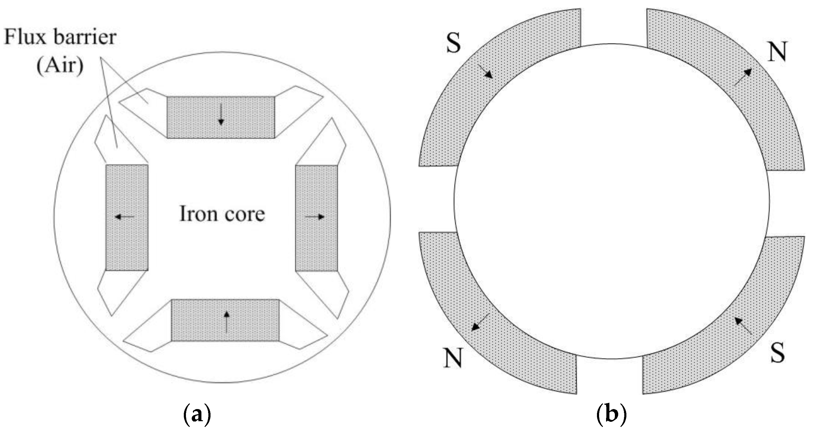
The conventional design method of PM machines is based on designer’s experience. To design a synchronous motor with excellent performance and economic cost, it is necessary to do optimal design of the structures of the PMs in the motor. Emerging from the development so far, the PMSM has a variety of different types of rotor PM structures. Overall, the basic three prominent PM arrangements of rotor structures are surface mounted magnets, radially magnetized magnets (embedded type), and circumferentially magnetized magnets (spoke type) [8,9,10,11]. Examples of surface mounted type and embedded type, which are involved in this article, are shown in Figure 1.
The performance of the PMSMs can be elevated by employing rare earth magnets [1,12,13]. In order to guarantee the designs of these machines in the best possible manner, many researches have been done in order to optimize the sizes of PMs [12,14]. From the early classical research works on single-phase PMSMs, to the extended works, wide detailed facets of the performances of this class of machines are covered, for example, torque behavior, power efficiency, and so on [13]. An approach to improve interior PM (IPM) synchronous motors was proposed in [15]. A technique of optimization of magnet shape of surface-mounted motor was carried out in [16]. In [17], finite-element method (FEM) was applied to analyze a PMSM with a slotted solid rotor, and an increment of electromagnetic torque was claimed.
For decades, the optimization methods have been applied to the design of induction machines. When more than one objective function is optimized simultaneously, the problem presents a set of solutions, which are referred to as Pareto Front [18]. It includes the solutions representing the best compromise satisfying all of the objectives. From the Pareto Front, the optimal solution of the optimization problem can be chosen by the designer’s balanced consideration on overall performance.
A multi-objective evolutionary algorithm for optimizing an IPM motor was brought out in Reference [19]. Then, some researchers developed the multi-objective optimization method further [20,21]. Methodology based on reluctance networks and multi-objective multi-level optimization by means of Non Dominated Sorting Genetic Algorithm II (NSGA-II) was presented in [22].
To achieve high efficiency, high torque, and other requirements, the state-of-the-art technologies for new generation of PMSM with improved features are currently based on different materials, including soft magnetic laminations and rare-earth elements (REEs) [23], among which rare-earth neodymium magnets (NdFeB) is highlighted [24]. Recent researches have the interest in the discovery of rare-earth-free materials with excellent PM properties [25]. Other materials, for example, ferrite magnet, have been studied to replace the NdFeB [26]. In this paper, a general pattern of PMSM that is practical for the NdFeB, which is widely applied in industry will be presented.
Usually the arrangement of PMs in the motor is based on designer’s experience, or multiple attempts of simulation. However, it could be difficult to take the performance of the motor and the cost into consideration at the same time. On the other hand, multiple attempts can cause a heavy computing load. In order to realize the preceding aims, many researchers have done works of automatic optimization design. For example, Laskaris [27] optimized the shape of magnetics in a surface mounted PM motor.
In this paper, the novel general pattern of PM arrangement can produce many different types of rotor structures. The general pattern can produce at least six most commonly used types of PM arrangements, as shown in Figure 2, including five embedded types and a typical surface-mounted type. The proposed general pattern is applied to the PMSM design. By varing the design parameters of the PM, the type of the PM structures can be determined automatically, which is the main advantage of this proposed method. Based on the analysis of the impact of the design parameters to objective functions, a strategy of sub-group optimization is also proposed. Then, a multi-objective optimization (MOP) will be applied based on this model. The whole process aims to find an optimal structure of PMs for the rotor of the PMSM with an acceptable cost of PMs. Finally, simulation test and experiment results will be given in this paper.
2. Basic Design of the PMSM
When the basic structure of the motor is settled, the designer needs to determine the geometry size of each part of the motor accordingly.
The inner diameter of the stator has a close relationship with electrical energy conversion ability. The larger the inner diameter of the stator is, the greater the energy conversion of equivalent volume is. However, if the inner diameter of the stator is too large, it will cause the reduction of stator space. When the outer stator diameter is fixed, the large inner diameter of the stator can make the stator yoke of thinning, and then the flux density in the yoke will be saturated easily. In this paper, the inner diameter of the stator is set as a main variable of the optimization.
In this paper, the motor as a typical example has 24 slots in the stator core. When designing the stator iron core, the main parameters are: the groove opening size, the width of tooth, and the thickness of the yoke. These are also set as variables of the optimization. With the proposed general pattern of PMSM, the structure of the rotor iron core can be designed by determining the parameters of the general pattern of PMs. These parameters should be able to make appropriate changes then lead to different shapes and the distribution of PMs.
3. General Pattern of the PMSM
The design aim of this paper is to elevate the torque per loss and control the comprehensive cost of the motor (including the cost of motor material, the cost of batch production process, etc.). Based on the proposed general pattern of PMs, one specific type, including one of the six possible types of rotor structures, can be determined automatically according to the values of the design parameters.
3.1. General Model of PMs
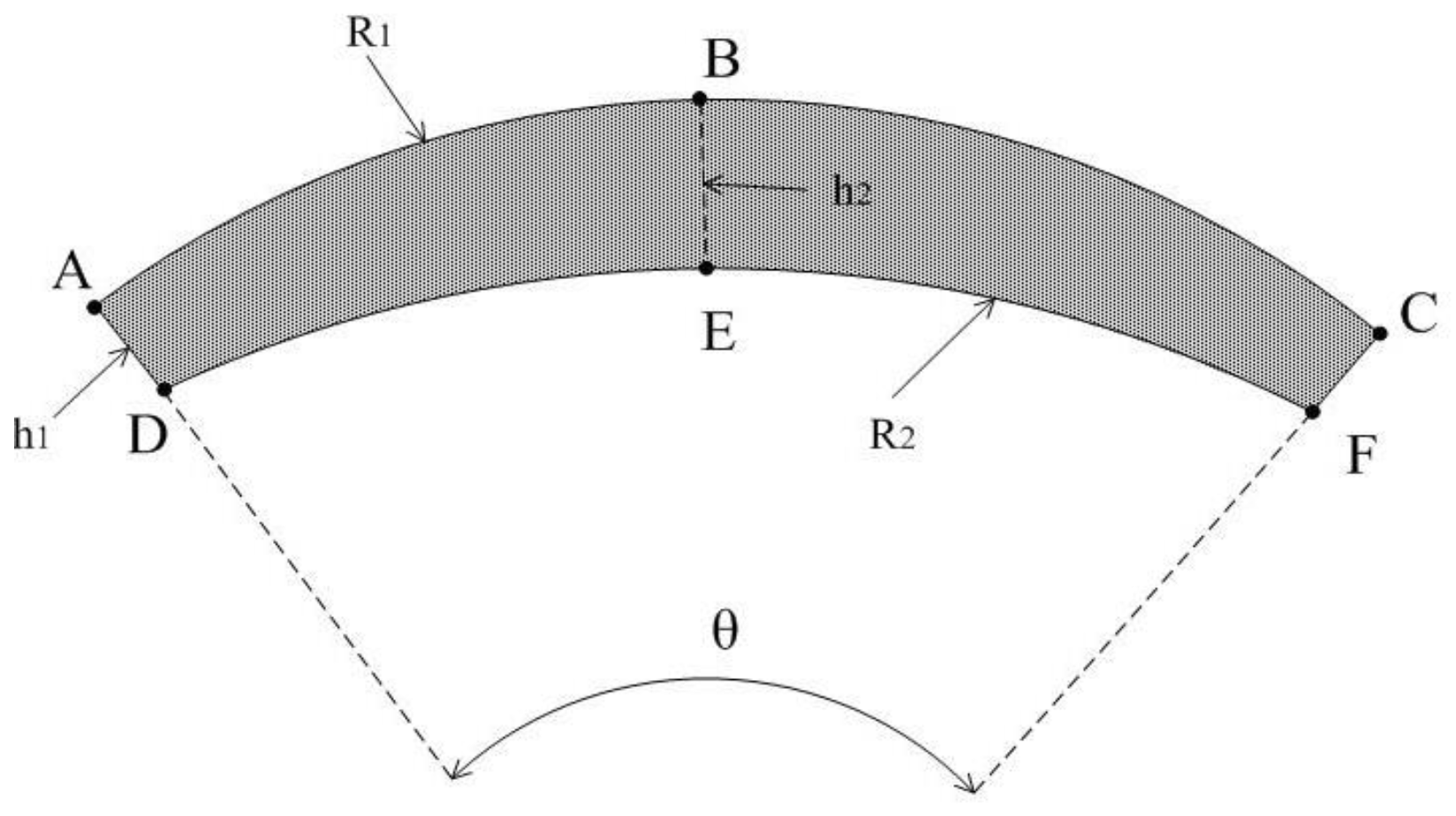
When considering that the shape of PM should be able to vary from a rectangular magnet pole of embedded PM to magnet tile pole of surface-mounted PM, the general shape of one piece of PM is presented as shown in Figure 3.
The magnetic tile is edged up and down by two three-point arcs: and . The corresponding radius of arc and are, respectively, R1 and R2. B is the midpoint of and E is the midpoint of . The thickness at AD is h1 and the thickness at BE is h2. h1 and h2 are not necessarily equal.
Suppose kA is the slope of , and kB is the slope of . kD is the slope of , and kE is the slope of .
If h1 = h2, then it is a magnet pole with constant thickness. When kA = kB, then the two arcs of the magnet pole model will be straight lines, and this means that this model should be a rectangle, as shown in Figure 4a. When kA ≠ kB, the shape of the magnet pole will be modified, as shown in Figure 4b. These two types of magnet pole are the most commonly used types in industry.
If h1 ≠ h2, then the magnet pole will have unequal thickness. When kA ≠ kB, and kD = kE, then the model will be modified, as shown in Figure 4c. When kA ≠ kB, and kD ≠ kE, then the model will be modified, as shown in Figure 4d. When the shape of the magnet pole is confirmed, its tilt angle and the location of magnet pole can be controlled by the design parameters.
Based on the general pattern of the PMs, an innovative PMSM may be generated.
3.2. Basic Data of the PMSM
Basic dimensions of the motor include the length of the iron core, the diameter of air gap, the sizes of stator silicon steel sheet, the rotor silicon steel sheet, and axis parts. The basic geometry sizes are listed in Table 1.
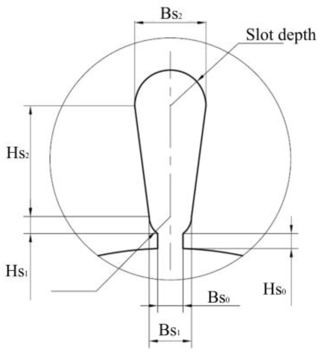
The design parameters Bs0, Bs1 Bs2, Hs0, Hs1, Hs2 of the slot are shown in Figure 5. In Table 2, sd is the slot depth. Di is the inner diameter of stator, and hy is the thickness of the stator yoke. In the optimization, the volume of the motor is stable, which means, the outer diameter of the stator is constant.
3.3. Parameters of the Optimization of the PMSM
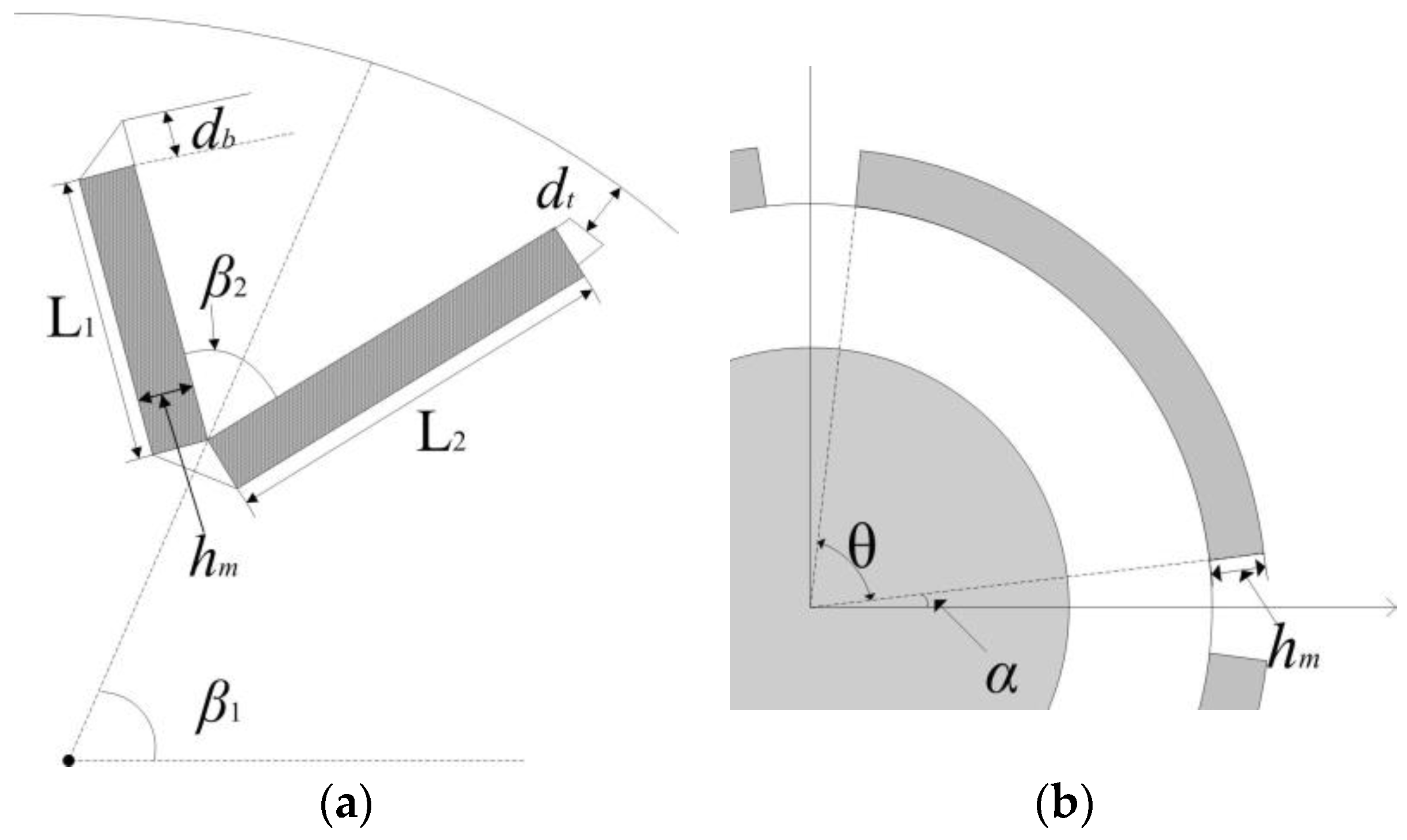
For different types of PMSM, the number of parameters may be different and the constraint conditions will be altered accordingly. Figure 6 shows the parameters for magnet pole for both embedded types and surface mounted types. Table 2 and Table 3 show the limitation of the values of the design variables. dt is the distance between the flux barrier and the outer surface of rotor. db is the length of the flux barrier. L1 and L2 are the length of two PMs. β1 and β2 are the angles of inclination for both PMs. hm is the thickness of the PMs.
Since the shape of the magnet pole should be capable of modification from rectangle to magnetic tile, a parameter Flg is defined,
Flg = kA/kB
In optimization, when the values of the parameters are settled, with the constraint conditions, the type of PMSM is determined and the corresponding electromagnetic field computation can be undertaken using FEM.
4. Multi-Objective Optimization
4.1. Setup of the Optimization Problem
Multi-objective optimization problems (MOPs) often appear in practical design processes. Setting proper objective functions and constraint conditions are essential for solving the MOPs.
In this paper, to evaluate the performance of the designed motor, one not only focuses on the torque, but also takes the total loss into consideration. Therefore, the first objective function is f1. It is defined as below. fTL is torque over loss, which is an indicator for observing the performance of the motor.
Another crucial aspect that needs to be considered during the design of PMSM is the cost. Since most variation of the cost happens on the PMs, in this work, the cost of PMs, which includes material expense, processing charge, and the average labor cost, is defined as the second objective function. Each cost function contains three parts: the cost of material, the cost of labor, and the cost of tooling. The cost of tooling is usually associated with additional mold manufacturing when the PM has uncommon shape. Based on the quotation from a motor manufacturing factory Ningbo Xingde Tech Co., Ltd, the cost of tooling is $3200. The objective function of the cost of PM is defined as,
where N is the number of pieces of PMs; V is the volume (cm3) of a single PM; and, k is the coefficient of the influence of shapes on the price:
s is the coefficient of difficulty for manufacturing:
and, ω is the factor that shows if the PM type is commonly used or not:
If the type of magnetic pole is uncommon, it will lead to an extra cost.
The optimization problem is described as below:
where f(X) is the objective functions; g(X) is the constraint condition. g1, g2 are constants. is the set of design parameters; n is the number of design parameters; and, m is the number of the constraint conditions.
- (1).
- If Flg > 1, and if 1.5 ≤ hm ≤ 4 mm, 1 ≤ α ≤ 3 deg and 83 ≤ θ ≤ 88 deg are established at the same time, then the coefficients for other parameters are set to be zero. This generated motor is surface mounted type.
- (2).
- If Flg = 1, and L1 = 0, then if 3 ≤ L2 ≤ 7 mm, 20 ≤ β2 ≤ 40 deg, 1.5 ≤ hm ≤ 4 mm, 1.5 ≤ dt ≤ 2 mm, and 0.3 ≤ db ≤ 1.2 mm are established at the same time, then the coefficients for other parameters are set to be zero. This generated motor is V type.
- (3).
- If Flg = 1, L1 > 0, then if β1 = 0 deg, 1.5 ≤ hm ≤ 4 mm, 1.5 ≤ dt ≤ 2 mm, and 0.3 ≤ db ≤ 1.2 mm, then the coefficients for other parameters are set to be zero. This generated motor is radial type.
- (4).
- If Flg = 1, L1 > 0, then if β1 = 90 deg, 1.5 ≤ hm ≤ 4 mm, 1.5 ≤ dt ≤ 2 mm, and 0.3 ≤ db ≤ 1.2 mm then the coefficients for other parameters are set to be zero. This generated motor is concentrate type.
- (5).
- If Flg = 1, L1 > 0, and L2 > 0, if 20 ≤ β1 ≤ 40 deg, 20 ≤ β2 ≤ 40 deg, 1.5 ≤ hm ≤ 4 mm, 1.5 ≤ dt ≤ 2 mm, and 0.3 ≤ db ≤ 1.2 mm are established at the same time, then the coefficients for other parameters are set to be zero. This generated motor is W type.
- (6).
- If Flg = 1, L1 > 0, and L2 > 0, if 20 ≤ β1 ≤ 40 deg, β2 = 120 deg, 1.5 ≤ hm ≤ 4 mm, 1.5 ≤ dt ≤ 2 mm, and 0.3 ≤ db ≤ 1.2 mm are established at the same time, then the coefficients for other parameters are set to be zero. This generated motor is U type.
In MOP, normally it is not able to achieve the optimum for all of the objective functions. The balance among different objective functions is necessary. The balance requests to obtain a Pareto non-dominated solution set. Based on the Pareto Front, the designers can find an appropriate solution for a compromise among all objective functions.
4.2. Sensitivity Analysis for the Design Parameters
In order to estimate the impact of the design parameters to the objective functions, sensitivity tests are carried out firstly. The tested design parameter changes with an increment, while all of the other parameters remain the same. The variation rate of a design parameter is defined as rp,
where Δx represents the variation of a variable. The range of the value of this variable is (xMin, xMax). As typical examples, when the rp changes from 10% to 100%, for the design parameters of the stator, the rates of change for the objective functions are shown in Table 4; for the W type embedded PMSM, the rates of change for the objective functions are shown in Table 5. Table 6 presents the results of the surface-mounted motor.
According to the results in three tables, it is obvious that in stator, all of the parameters only affect the objective function fTL. The parameters Di, hy, and sd have larger impact on the value of objective function fTL than other parameters. On the rotor, the angles of the PM and the size of magnetic isolation bridges also only have impact on fTL. Moreover, the parameters indicating the size of the PMs have more effect to both objective functions than other parameters.
4.3. Sub-Group Optimization Strategy
The MOP, with dozens of design parameters, would need a large amount of computation as FEM is employed to simulate the operation of electric machines. Usually the process may take several days. It is also a hotspot for researchers to find out a practical methodology to reduce the computing load. By analyzing the sensitivities of design parameters, as shown in Table 4, Table 5 and Table 6, the design parameters can be divided into two types: the ones have larger effect on the objective functions and the others have less effect.
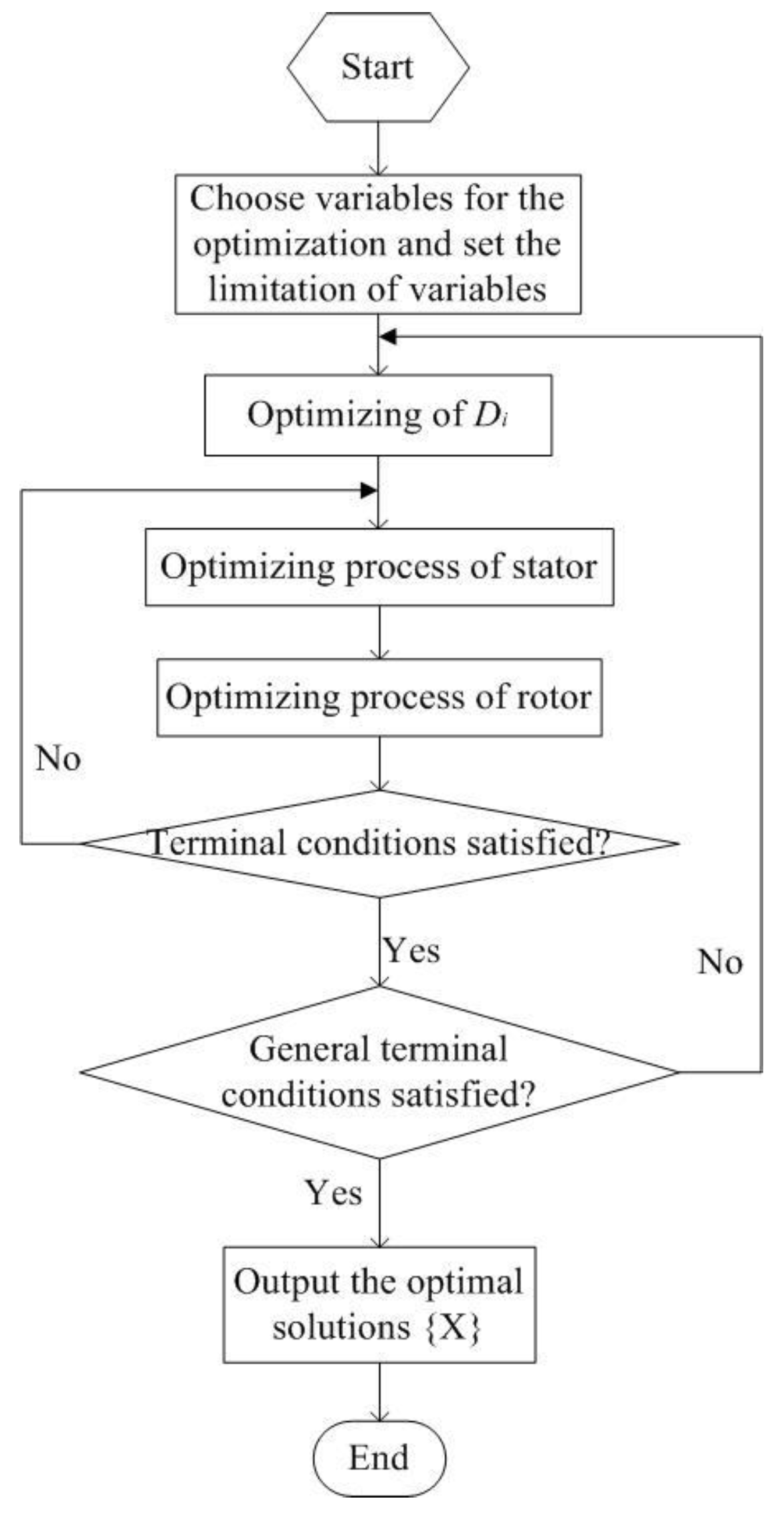
Di is an essential parameter that can affect the geometrical size of both the stator and rotor. Hence, in the optimization, the optimization of Di is pulled out as the first loop of the entire optimizing process, which is illustrated in Figure 7. Golden section method is applied for this one-dimensional optimization.
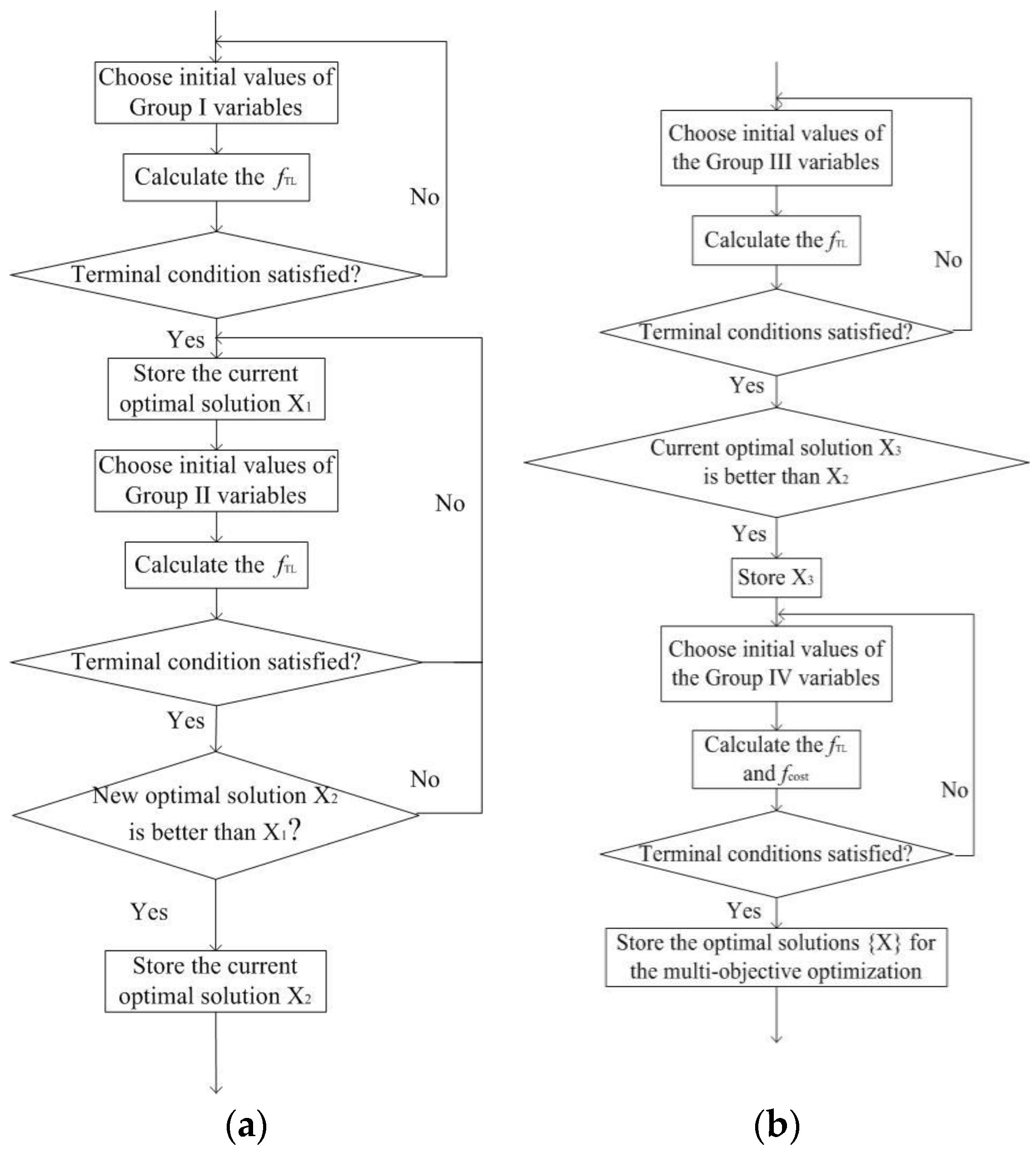
Moreover, in the stator side, the parameters hy, and sd constitute the parameters of Group I, and the other six parameters constitute the Group II.
Since the variables of Group I and Group II only affect one objective function that is associated with torque, single-objective optimization method is applied at these processes. In this paper, a particle swarm optimization (PSO) [28] is employed. It is a global searching algorithm, which has fast convergence and strong versatility.
On the rotor side, the parameters of positions of the magnetic pole: β1, β2, dt, db, and α constitute Group III. Optimization of Group III is also single-objective optimization process, so PSO is homologously applied at this part of process. The parameters of magnetic pole size are: hm, L1, L2, and θ constitute Group IV. These variables may affective the values of both objective functions. Hence NSGA-II is employed for applying the optimization process of Group IV.
4.4. Result of the MOP
Multi-objective evolutionary algorithms (EAs) that use nondominated sorting and sharing have been criticized mainly for three parts: (1) O(MN3) computational complexity (M is the number of objectives and N is the population size); (2) nonelitism approach; and, (3) the need for specifying a sharing parameter. NSGA-II, which is a nondominated sorting-based algorithm, can alleviate all of the above three difficulties. Specifically, it is a fast nondominated sorting approach with O(MN2) computational complexity [29].
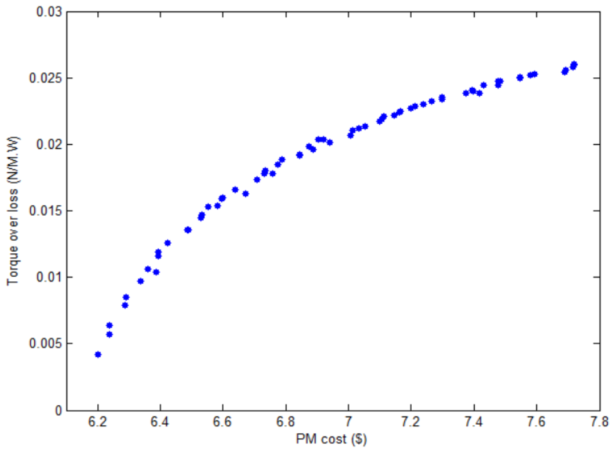
The Pareto Front of the MOP is shown as in Figure 9. One point in the figure represents one of the Pareto solutions.
In this article, the torque over loss should be maximized while the cost of PMs is minimized. Hence the final solution usually can be chosen in the middle part of the Pareto Front. The NSGA-II employed in this work is a random algorithm, so the Pareto Front for different operation will be disparity. The optimization process is repeated for three times, and two optimal solutions are chosen at each time. Six optimal solutions are listed in the Table 7.
5. Experimental Verification of Optimized PMSM
After the optimization process is completed, in order to compare the simulation results with the practical experiment results, a prototype is manufactured according to the optimized design parameters. The material of the PMs in the motor is N35. The B-H curve of N35 is shown in Figure 10.
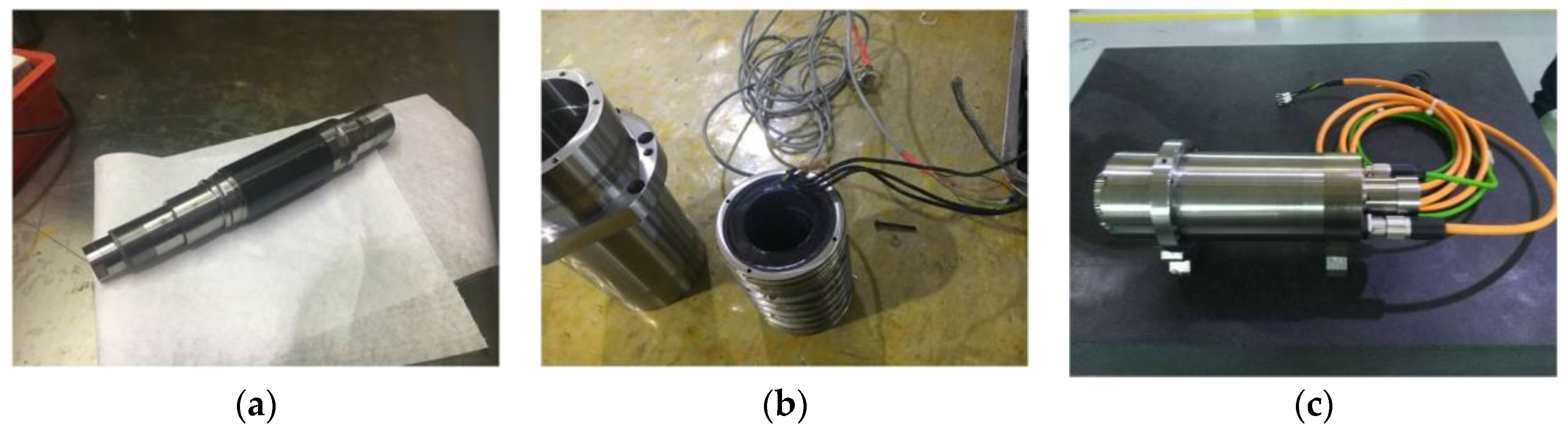
The structure of the prototype is shown from Figure 11a–c.
The material of magnetic poles is NdFeb PM material, and the type of silicon steel sheet is DG41. It is the electrical steel sheet with thickness of 0.35 mm. Under the 400 Hz alternate frequency, and magnetic induction intensity for 10 T, the iron loss density is 11 W.
In order to test the accuracy of the simulation, the no-load back electromotive force under different rotating speed is simulated and experimentally measured. The results are compared in Table 9. The electromagnetic torque is also an essential indicator of the performance of the motor. To test the torque under certain rotating speeds and load currents, the setup of the motor with torque flange for experiment is shown in Figure 12. The comparison of the simulation results and the experimental results are shown in Table 10. From the comparisons of computed and measured electromotive force and torque, it is noticeable that the simulation results are accurate.
A typical magnetic flux distribution and flux density distribution of the magnetic field analysis of the motor is shown as in Figure 13.
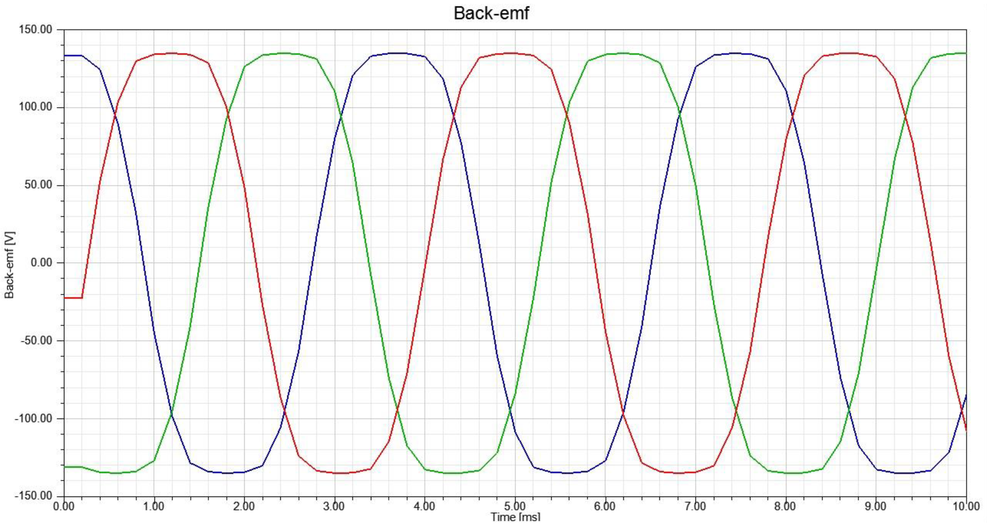
No-load back electromotive force is one of the performance parameters that needs to be addressed when designing the PMSM. The no-load back electromotive force for the designed prototype under the rated speed is shown in Figure 14.
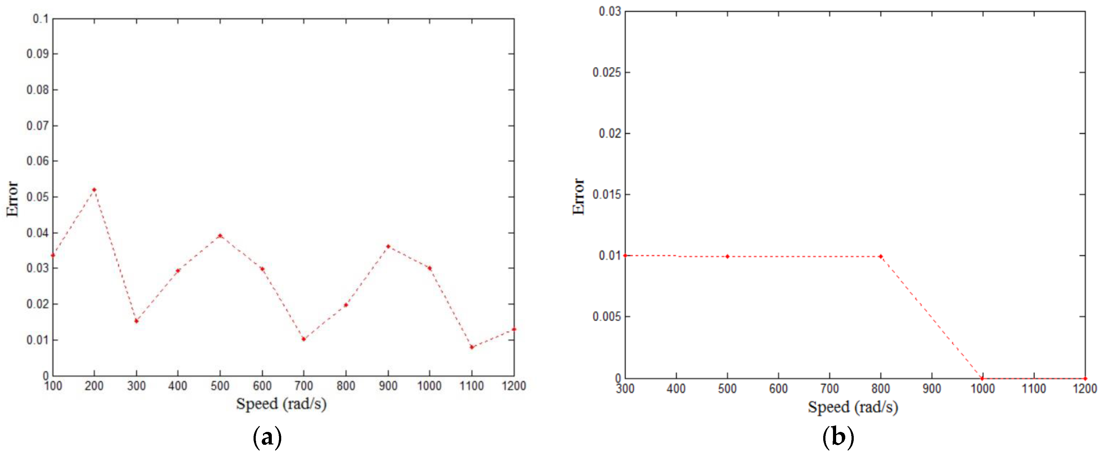
The error between the simulation result and experiment result is defined as in (6). The error level of the simulation results is presented in Figure 15a,b. It is obvious that the error level of back electromotive force is below 6% and the error level of the torque is below 1%.
6. Conclusions
In this paper, the parameters on both stator and rotor are chosen as the design variables, with the torque over loss and the PM cost as objective functions. A general model of magnetic poles is presented and applied in the optimization of PMSM. Both single-objective optimization and multi-objective optimization algorithms are employed in this work. The sensitivity analysis of the design parameters helps to determine the impact levels of the design parameters to the objective functions. Based on the sensitivity analysis, a sub-group optimization strategy is presented. After the optimization using PSO, the structure of stator achieves the optimum temporarily. Then, the multi-objective optimization using NSGA-II begins. When the optimization process is complete, in the Pareto solution set, a final optimal solution is chosen as the design of the prototype motor. In the end, the simulation outcomes compare with the experimental outcomes, which shows that the simulation is accurate. Generally, the technique proposed in this paper is feasible and accurate in optimization design of the PM structures of the rotor for the PMSM. It can help designers to decide which type of PMs is proper for a specific application.
Acknowledgments
This work was supported by the Research Grant Council of the Hong Kong Special Administrative Region Government under projects PolyU 5153/13E and PolyU 152050/14E.
Author Contributions
Xiaoyu Liu and Weinong Fu proposed the methodology; Qifang Lin worked on the modeling and performed the experiments; Xiaoyu Liu wrote the paper.
Conflicts of Interest
The authors declare no conflict of interest.
References
- Isfahani, A.H.; Vaez-Zadeh, S. Line start permanent magnet synchronous motors: Challenges and opportunities. Energy 2009, 34, 1755–1763. [Google Scholar] [CrossRef]
- Melfi, M.J.; Rogers, S.D.; Evon, S.; Martin, B. Permanent-Magnet Motors for Energy Savings in Industrial Applications. IEEE Trans. Ind. Appl. 2008, 44, 1360–1366. [Google Scholar] [CrossRef]
- Cavallaro, C.; di Tommaso, A.O.; Miceli, R.; Raciti, A.; Galluzzo, G.R.; Trapanese, M. Efficiency enhancement of permanent-magnet synchronous motor drives by online loss minimization approaches. IEEE Trans. Ind. Electron. 2005, 52, 1153–1160. [Google Scholar] [CrossRef]
- Liu, L.; Liu, W.; Cartes, D.A. Particle swarm optimization-based parameter identification applied to permanent magnet synchronous motors. Eng. Appl. Artif. Intell. 2008, 21, 1092–1100. [Google Scholar] [CrossRef]
- Colby, R.S.; Novotny, D.W. An Efficiency-Optimizing Permanent-Magnet Synchronous Motor Drive. IEEE Trans. Ind. Appl. 1988, 24, 462–469. [Google Scholar] [CrossRef]
- Li, Y.; Zou, J.; Lu, Y. Optimum design of magnet shape in permanent magnet synchronous motors. IEEE Trans. Magn. 2003, 39, 3523–3526. [Google Scholar]
- Islam, R.; Husain, I.; Fardoun, A.; McLaughlin, K. Permanent-Magnet Synchronous Motor Magnet Designs with Skewing for Torque Ripple and Cogging Torque Reduction. IEEE Trans. Ind. Appl. 2009, 45, 152–160. [Google Scholar] [CrossRef]
- Singh, B.; Singh, B.P. State of the Art on Permanent Magnet Brushless DC Motor Drives. J. Power Electron. 2009, 9, 1–17. [Google Scholar]
- Knight, A.M.; McClay, C.I. The design of high-efficiency line-start motors. IEEE Trans. Ind. Appl. 2000, 36, 1555–1562. [Google Scholar]
- Rahman, K.K.M.A. High-efficiency line start interior permanent magnet synchronous motors. IEEE Trans. Ind. Appl. 2004, 40, 789–796. [Google Scholar]
- Kim, W.H.; Kim, K.C.; Kim, S.J.; Kang, D.W.; Go, S.C.; Lee, H.W.; Chun, Y.D.; Lee, J. A Study on the Optimal Rotor Design of LSPM Considering the Starting Torque and Efficiency. IEEE Trans. Magn. 2009, 45, 1808–1811. [Google Scholar] [CrossRef]
- Baek, S.-W.; Kwon, B.-I. Optimum design of a single phase line start PM motor considering efficiency, aximum torque, and starting torque. IEEE Trans. Magn. 2012, 48, 4850–4859. [Google Scholar] [CrossRef]
- Popescu, M.; Miller, T.J.E.; McGilp, M.I.; Strappazzon, G.; Trivillin, N.; Santarossa, R. Line-start permanent-magnet motor: Single-phase starting performance analysis. IEEE Trans. Ind. Appl. 2003, 9, 1021–1030. [Google Scholar] [CrossRef]
- Ding, T.; Takorabet, N.; Sargos, F.; Wang, X. Design and Analysis of Different Line-Start PM Synchronous Motors for Oil-Pump Applications. IEEE Trans. Magn. 2009, 45, 1816–1819. [Google Scholar] [CrossRef]
- Khlaief, A.; Boussak, M.; Gossa, M. Model reference adaptive system based daptive speed estimation for sensorless vector control with initial rotor position estimation for interior permanent magnet synchronous motor drive. Electr. Power Compon. Syst. 2012, 41, 47–74. [Google Scholar] [CrossRef]
- Chai, F.; Liang, P.; Pei, Y.; Cheng, S. Magnet Shape Optimization of Surface-Mounted Permanent-Magnet Motors to Reduce Harmonic Iron Losses. IEEE Trans. Magn. 2016, 52, 6301304. [Google Scholar] [CrossRef]
- Azari, M.N.; Mirsalim, M. Performance analysis of a line start permanent magnet motor with slots on solid rotor using finite element method. Electr. Power Compon. Syst. 2013, 41, 1159–1172. [Google Scholar] [CrossRef]
- Parsopoulos, K.E.; Vrahatis, M.N. Particle swarm optimization method in multiobjective problems. In Proceedings of the 2002 ACM Symposium on Applied Computing (SAC ’02), Madrid, Spain, 11–14 March 2002; pp. 603–607. [Google Scholar]
- Ray, S.; Lowther, D.A. Multi-Objective Optimization Applied to the Matching of a Specified Torque-Speed Curve for an Internal Permanent Magnet Motor. IEEE Trans. Magn. 2009, 45, 1518–1521. [Google Scholar] [CrossRef]
- Silva, R.; Salimi, A.; Li, M.; Freitas, A.R.R.; Guimaraes, F.G.; Lowther, D.A. Visualization and Analysis of Tradeoffs in Many-Objective Optimization: A Case Study on the Interior Permanent Magnet Motor Design. IEEE Trans. Magn. 2016, 52, 8102404. [Google Scholar] [CrossRef]
- Barba, P.D.; Dughiero, F.; Mognaschi, M.E.; Savini, A.; Wiak, S. Biogeography-Inspired Multi-objective Optimization and MEMS Design. IEEE Trans Magn. 2016, 52, 7201504. [Google Scholar] [CrossRef]
- Hassan, M.H.; Krebs, G.; Remy, G.; Marchand, C. Multi-objective optimization of an Axial-Flux PM Actuator with space mapping technique. In Proceedings of the 9th IET International Conference on Computation in Electromagnetics, London, UK, 31 March–1 April 2014; pp. 4–14. [Google Scholar]
- Habib, K.; Wenzel, H. Exploring rare earths supply constraints for the emerging clean energy technologies and the role of recycling. J. Clean. Prod. 2014, 84, 348–359. [Google Scholar] [CrossRef]
- Ramsden, V.S.; Watterson, P.A.; Hunter, G.P.; Zhu, J.G.; Holliday, W.M.; Lovatt, H.C.; Wu, W.; Kalan, B.A.; Collocott, S.J.; Dunlop, J.B.; et al. High-performance electric machines for renewable energy generation and efficient drives. Renew. Energy 2001, 22, 159–167. [Google Scholar] [CrossRef]
- Sellmyer, D.J.; Balamurugan, B.; Zhang, W.Y.; Das, B.; Skomski, R.; Kharel, P.; Liu, Y. Advances in Rare-Earth-Free Permanent Magnets. In Proceedings of the 8th Pacific Rim International Congress on Advanced Materials and Processing 2013 (PRICM 8), Waikoloa, HI, USA, 4–9 August 2013; pp. 1689–1696. [Google Scholar]
- Riba, J.; López-Torres, C.; Romeral, L.; Garcia, A. Rare-earth-free propulsion motors for electric vehicles: A technology review. Renew. Sustain. Energy Rev. 2016, 57, 367–379. [Google Scholar] [CrossRef]
- Laskaris, K.I.; Kladas, A.G. Permanent-Magnet Shape Optimization Effects on Synchronous Motor Performance. IEEE Trans. Ind. Electron. 2011, 58, 3776–3783. [Google Scholar] [CrossRef]
- Liu, L.; Cartes, D.A. A particle swarm optimization approach for automatic diagnosis of PMSM stator fault. In Proceedings of the American Control Conference, Minneapolis, MN, USA, 14–16 June 2006. [Google Scholar]
- Deb, K.; Pratap, A.; Agarwal, S.; Meyarivan, T. A fast and elitist multiobjective genetic algorithm: NSGA-II. IEEE Trans. Evolut. Comput. 2002, 6, 182–197. [Google Scholar] [CrossRef]
Figure 1.
Permanent magnet synchronous motors (PMSM) rotor structures. (a) Embedded type; (b) Surfaced-mounted type.
Figure 1.
Permanent magnet synchronous motors (PMSM) rotor structures. (a) Embedded type; (b) Surfaced-mounted type.

Figure 2.
Most commonly employed rotor types. (a) Concentrate type; (b) Radial type; (c) U type; (d) V type; (e) W type; (f) Surface mounted type.
Figure 2.
Most commonly employed rotor types. (a) Concentrate type; (b) Radial type; (c) U type; (d) V type; (e) W type; (f) Surface mounted type.
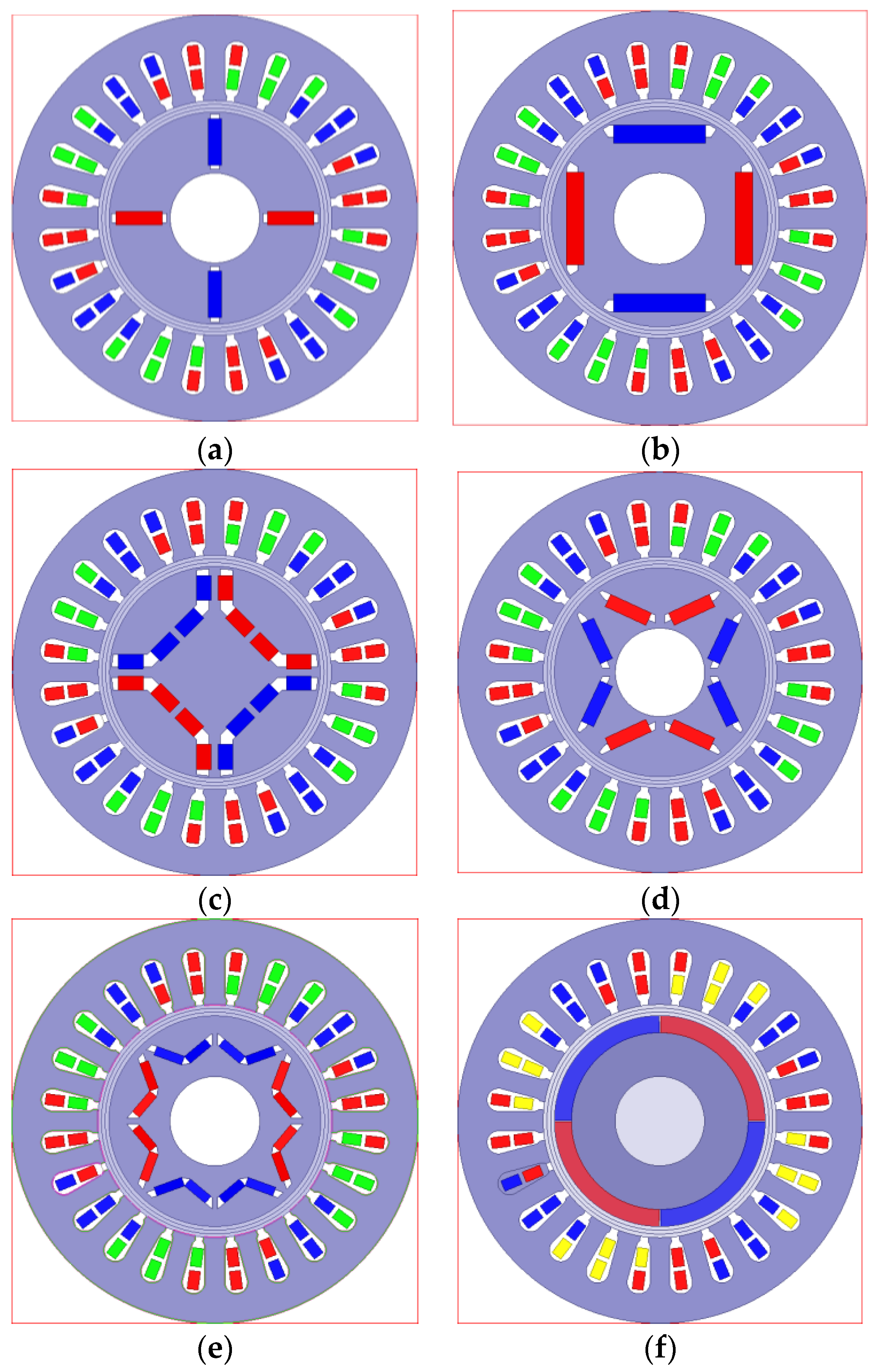
Figure 3.
General pattern of one piece of permanent magnet (PM).

Figure 4.
Possible shapes of magnet pole produced from the general pattern. (a) Straight PM with uniform thickness; (b) Bending PM with uniform thickness; (c) Straight PM with uneven thickness; (d) Bending PM with uneven thickness.
Figure 4.
Possible shapes of magnet pole produced from the general pattern. (a) Straight PM with uniform thickness; (b) Bending PM with uniform thickness; (c) Straight PM with uneven thickness; (d) Bending PM with uneven thickness.
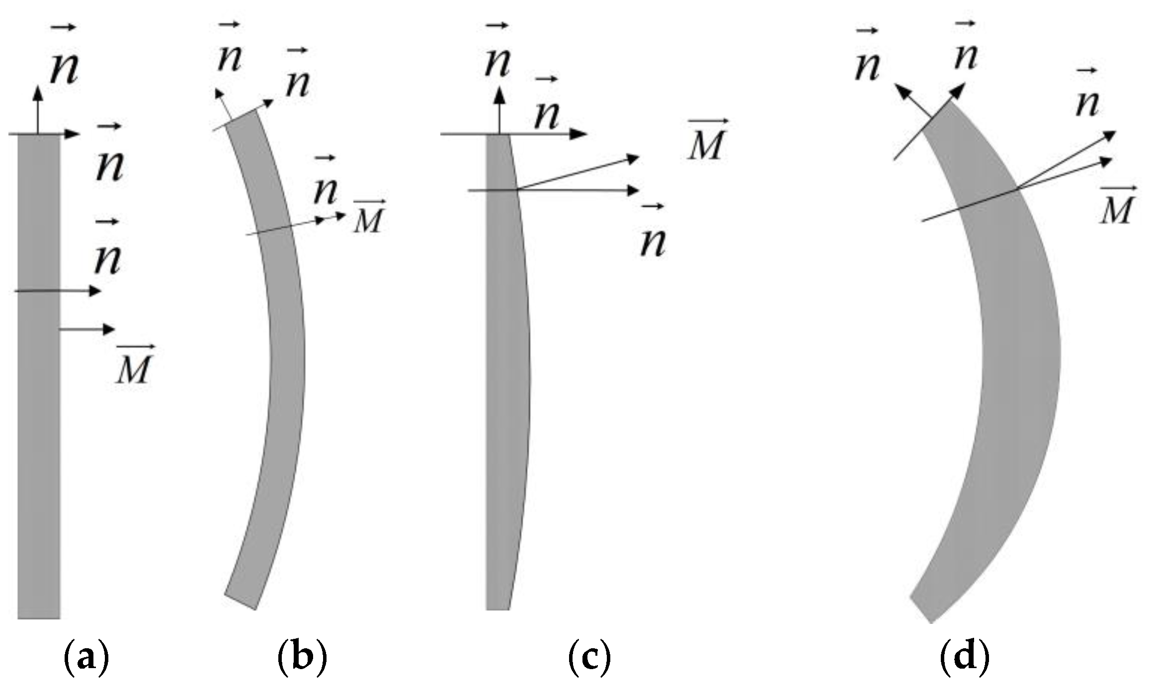
Figure 5.
Design parameters of the stator slot.

Figure 6.
Design parameters of the PMs. (a) Embedded type; (b) Surface-mounted type.

Figure 7.
Flow chart of the sub-group optimization.

Figure 8.
Optimization processes of stator and rotor. (a) Stator; (b) Rotor.

Figure 9.
The Pareto Front of the multi-objective optimization (MOP).

Figure 10.
B-H curves of N35.
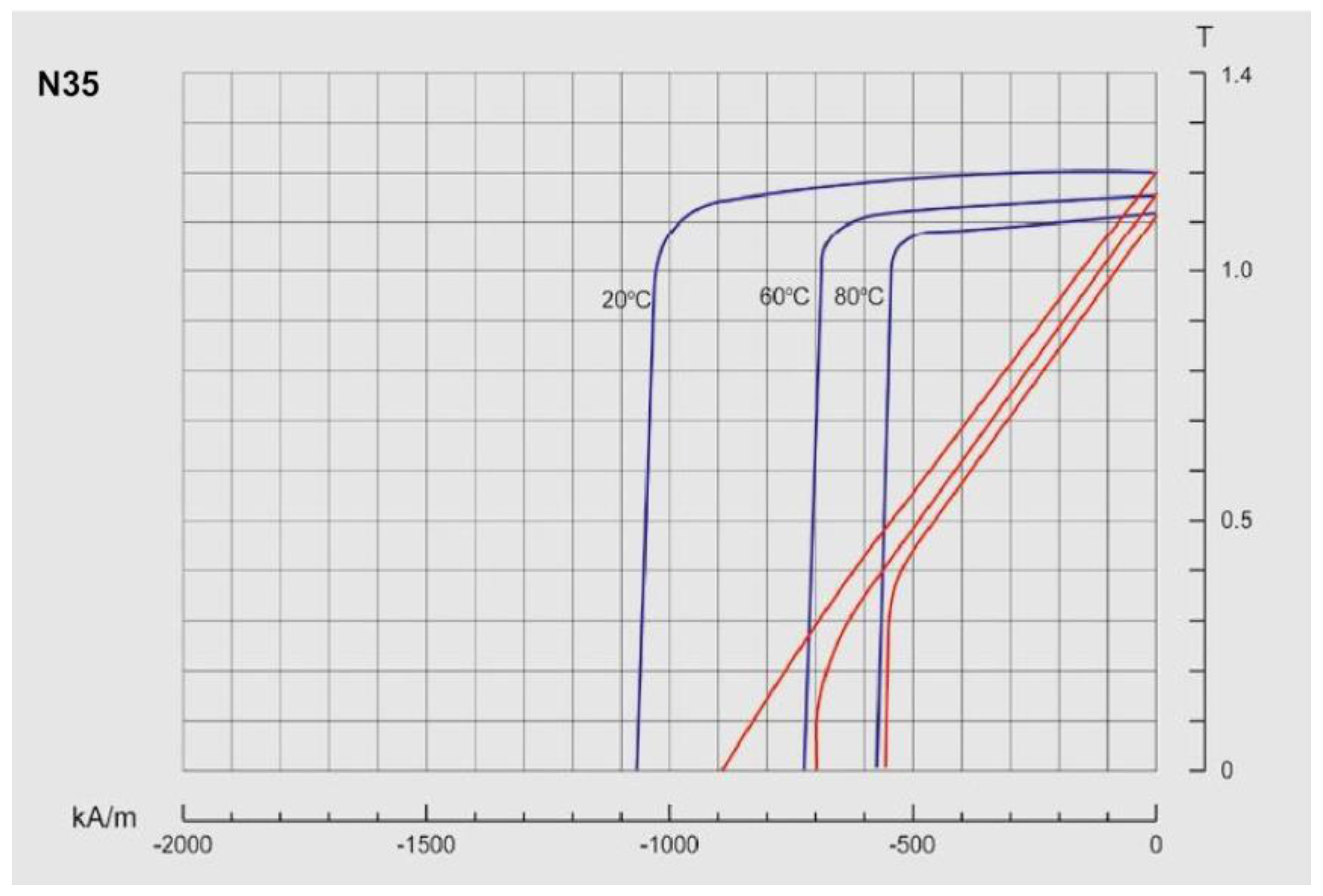
Figure 11.
(a) The rotor with carbon fiber sleeve; (b) The appearance of stator; (c) The appearance of the prototype motor.
Figure 11.
(a) The rotor with carbon fiber sleeve; (b) The appearance of stator; (c) The appearance of the prototype motor.

Figure 12.
The prototype with torque flange.
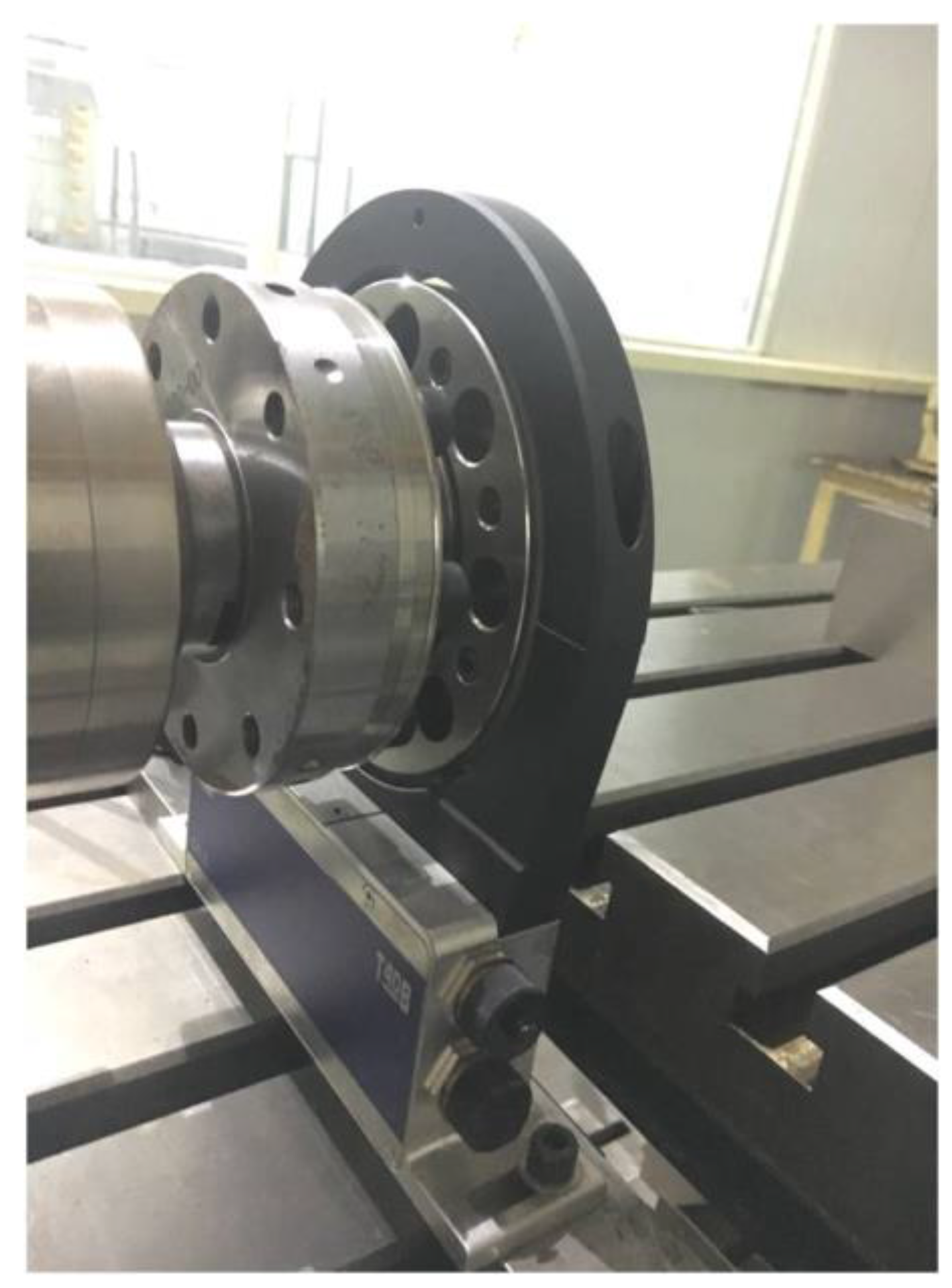
Figure 13.
The electromagnetic field analysis of the prototype. (a) Flux lines; (b) The magnetic flux density distribution.
Figure 13.
The electromagnetic field analysis of the prototype. (a) Flux lines; (b) The magnetic flux density distribution.
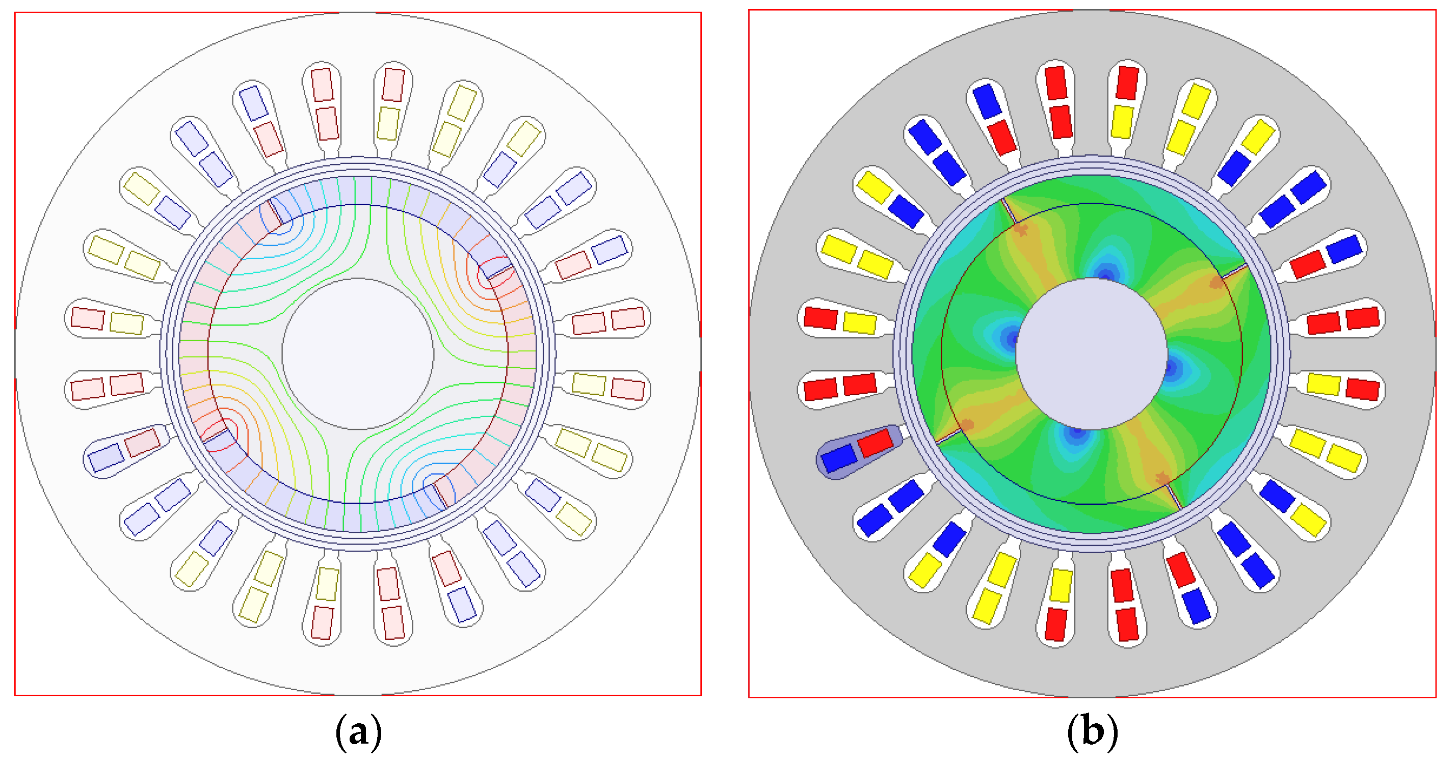
Figure 14.
No-load back electromotive force.

Figure 15.
(a) The error level of the simulation results of back electromotive force; (b) The error level of the simulation results of torque.
Figure 15.
(a) The error level of the simulation results of back electromotive force; (b) The error level of the simulation results of torque.

Table 1.
Basic geometrical size of the PMSM motor.
| Type | Name | Value |
|---|---|---|
| Motor | Air gap | 2.51 mm |
| Length of the iron core | 90 mm | |
| Rated voltage | 220 V | |
| Rated power | 7.5 kW | |
| Stator | Number of slots | 24 |
| Outer diameter of stator | 90.5 mm | |
| Rated current | 25 A | |
| Rotor | Number of pole pairs | 2 |
| Rotation speed | 8000 rpm | |
| Axle | Outer diameter | 20 mm |
Table 2.
Design variables of the stator.
| Type | Design Parameters | Value Ranges |
|---|---|---|
| Stator | Di | 48–55 mm |
| Bs0 | 0.2–0.5 mm | |
| Bs1 | 0.1–0.3 mm | |
| Bs2 | 0.8–1.5 mm | |
| Hs0 | 0.8–1.2 mm | |
| Hs1 | 2.0–2.5 mm | |
| Hs2 | 1.5–2.5 mm | |
| sd | 9–13 mm | |
| hy | 15–22 mm |
Table 3.
Design variables of the rotor.
| Type | Design Parameters | Value Ranges |
|---|---|---|
| Rotor | Flg | 1–10 |
| hm | 1.5–4 mm | |
| α | 1–3 deg | |
| θ | 83–88 deg | |
| dt | 1.5–2 mm | |
| db | 0.3–1.2 mm | |
| β1 | 20–90 deg | |
| β2 | 20–120 deg | |
| L1 | 3–7 mm | |
| L2 | 3–7 mm |
Table 4.
Sensitivity analysis of the stator.
| Name | Rates of Change for fTL | ||||
|---|---|---|---|---|---|
| rp = 0.1 | rp = 0.2 | rp = 0.4 | rp = 0.8 | rp = 1 | |
| Di | 2.73 | 2.61 | 2.87 | 2.45 | 2.56 |
| hy | 2.11 | 2.09 | 2.17 | 2.14 | 2.01 |
| sd | 2.45 | 2.45 | 2.44 | 2.44 | 2.44 |
| Hs0 | 0.09 | 0.07 | 0.07 | 0.08 | 0.09 |
| Hs1 | 0.10 | 0.07 | 0.09 | 0.09 | 0.08 |
| Hs2 | 0.06 | 0.08 | 0.007 | 0.09 | 0.09 |
| Bs0 | 0.03 | 0.03 | 0.04 | 0.05 | 0.05 |
| Bs1 | 0.11 | 0.10 | 0.11 | 0.09 | 0.09 |
| Bs2 | 0.09 | 0.12 | 0.12 | 0.10 | 0.10 |
Table 5.
Sensitivity analysis of the rotor.
| Name | Rates of Change for fTL | Rates of Change for fcost | ||||
|---|---|---|---|---|---|---|
| rp = 0.2 | rp = 0.4 | rp = 0.8 | rp = 0.2 | rp = 0.4 | rp = 0.8 | |
| hm | 1.65 | 1.63 | 1.59 | 0.21 | 0.20 | 0.19 |
| L1 | 3.72 | 3.64 | 3.66 | 0.19 | 0.24 | 0.23 |
| L2 | 3.16 | 3.24 | 3.23 | 0.20 | 0.21 | 0.25 |
| β1 | 0.41 | 0.43 | 0.42 | / | / | / |
| β2 | 0.33 | 0.35 | 0.34 | / | / | / |
| dt | 0.03 | 0.03 | 0.02 | / | / | / |
| db | 0.02 | 0.02 | 0.02 | / | / | / |
Table 6.
Sensitivity analysis of the surface-mounted type of rotor.
| Name | Rates of Change for fTL | Rates of Change for fcost | ||||
|---|---|---|---|---|---|---|
| rp = 0.2 | rp = 0.4 | rp = 0.8 | rp = 0.2 | rp = 0.4 | rp = 0.8 | |
| hm | 1.81 | 1.85 | 1.83 | 0.21 | 0.21 | 0.22 |
| θ | 2.12 | 2.13 | 2.10 | 0.19 | 0.23 | 0.20 |
| α | 0.35 | 0.37 | 0.33 | / | / | / |
Table 7.
Optimal solutions of the MOP.
| Number | Type of Motor | fTL (N/M‧W) | fcost ($) |
|---|---|---|---|
| 1 | Concentrate | 0.011 | 6.62 |
| 2 | Surface-mounted | 0.022 | 7.14 |
| 3 | V type | 0.017 | 7.06 |
| 4 | Surface-mounted | 0.025 | 7.38 |
| 5 | V type | 0.013 | 6.82 |
| 6 | Surface-mounted | 0.024 | 7.27 |
Table 8.
Finial solutions of the MOP.
| Design Parameter | Value | Design Parameter | Value |
|---|---|---|---|
| Di (mm) | 52.22 | Bs0 (mm) | 0.02 |
| hy (mm) | 7.84 | Bs1 (mm) | 3.08 |
| sd (mm) | 11.30 | Bs2 (mm) | 8.71 |
| Hs0 (mm) | 1.09 | hm (mm) | 3.80 |
| Hs1 (mm) | 2.22 | θ (deg) | 89 |
| Hs2 (mm) | 7.99 | α (deg) | 0.5 |
Table 9.
No-load back electromotive force under different rotating speeds.
| Speed (rad/s) | Simulation Results of EMF (V) | Experiment Results of EMF (V) |
|---|---|---|
| 100 | 24.6 | 23.8 |
| 200 | 50.5 | 48 |
| 300 | 73.1 | 72 |
| 400 | 98.6 | 95.8 |
| 500 | 124.4 | 119.7 |
| 600 | 147.9 | 143.6 |
| 700 | 169.2 | 167.5 |
| 800 | 195.1 | 191.3 |
| 900 | 223 | 215.2 |
| 1000 | 246.2 | 239 |
| 1100 | 264.9 | 262.8 |
| 1200 | 290.4 | 286.7 |
Table 10.
Electromagnetic torque under different phase current.
| Speed (rad/s) | Current (A) | Simulation Results of Torque (N/M) | Experiment Results of Torque (N/M) |
|---|---|---|---|
| 300 | 25 | 9.9 | 10 |
| 500 | 25.6 | 10.2 | 10.1 |
| 800 | 25.6 | 10.0 | 10.1 |
| 1000 | 25 | 9.9 | 9.9 |
| 1200 | 24.5 | 9.7 | 9.7 |
© 2017 by the authors. Licensee MDPI, Basel, Switzerland. This article is an open access article distributed under the terms and conditions of the Creative Commons Attribution (CC BY) license (http://creativecommons.org/licenses/by/4.0/).
Share and Cite
MDPI and ACS Style
Liu, X.; Lin, Q.; Fu, W. Optimal Design of Permanent Magnet Arrangement in Synchronous Motors. Energies 2017, 10, 1700. https://doi.org/10.3390/en10111700
AMA Style
Liu X, Lin Q, Fu W. Optimal Design of Permanent Magnet Arrangement in Synchronous Motors. Energies. 2017; 10(11):1700. https://doi.org/10.3390/en10111700
Chicago/Turabian StyleLiu, Xiaoyu, Qifang Lin, and Weinong Fu. 2017. "Optimal Design of Permanent Magnet Arrangement in Synchronous Motors" Energies 10, no. 11: 1700. https://doi.org/10.3390/en10111700
Note that from the first issue of 2016, this journal uses article numbers instead of page numbers. See further details here.