Stability Analysis of Aircraft Power Systems Based on a Unified Large Signal Model


1
Key Laboratory of Smart Grid of Ministry of Education, Tianjin University, Tianjin 300072, China
2
Department of Power Consumption, China Electric Power Research Institute, Beijing 100192, China
3
Department of Electrical Engineering, Northeast Electric Power University, Jilin 132012, China
4
China Energy Equipment CO., LTD. 2, Beijing 100044, China
*
Author to whom correspondence should be addressed.
Energies 2017, 10(11), 1739; https://doi.org/10.3390/en10111739
Submission received: 5 September 2017
/
Revised: 25 September 2017
/
Accepted: 26 October 2017
/
Published: 30 October 2017
Abstract
:Complex power electronic conversion devices, most of which have high transmission performance, are important power conversion units in modern aircraft power systems. However, these devices can also affect the stability of the aircraft power system more and more prominent due to their dynamic and nonlinear characteristics. To analyze the stability of aircraft power systems in a simple, accurate and comprehensive way, this paper develops a unified large signal model of aircraft power systems. In this paper, first the Lyapunov linearization method and the mixed potential theory are employed to analyze small signal and large signal stability, respectively, and then a unified stability criterion is proposed to estimate small and large signal stability problems. Simulation results show that the unified large signal model of aircraft power systems presented in this paper can be used to analyze the stability problem of aircraft power systems in an accurate and comprehensive way. Furthermore, with simplicity, universality and structural uniformity, the unified large signal model lays a good foundation for the optimal design of aircraft power systems.
1. Introduction
At present, countries around the world have begun to consider issues of energy consumption and environmental pollution comprehensively, combined with the current status of their national economy and social development. To save energy, reduce costs and improve the performance of aircraft systems, electricity is increasingly being adopted in modern aircraft as a form of energy supply instead of the hydraulic and barometric energy used in traditional aircraft [1,2,3]. Therefore, the safe operation of aircraft now depends to a great degree on their electric power systems, as the concept of multiple electricity uses is gradually penetrating into the design of future aircraft.
Aircraft power systems are primarily responsible for power generation, conversion and distribution. More importantly, aircraft power systems needs to transmit electricity to the loads safely and appropriately. More electric aircraft provide electric power drives for the secondary power components with the help of a large number of power electronic conversion devices, such as autotransformer rectifiers (ATRUs), buck/boost converters [4,5], etc., which provide great convenience in the operation and control of aircraft, however, due to the dynamic, nonlinear, cascading and parallel connections of power electronic devices, the stability of aircraft power systems becomes a more and more prominent issue when high performance in necessary [6,7]. In addition, most of the load equipment in more electric aircraft power systems can be regarded as a constant power load (CPL) due to the fast response characteristics of controllers [8,9], and its negative impedance characteristics are seriously harmful to the stability of aircraft power systems. Therefore, the stability analysis electric aircraft power systems has become an important research topic, including power system modeling and simulation, small signal and large signal stability analysis, etc.
Aircraft power systems are a strong nonlinear systems; therefore it is relatively complicated to develop a precise model for the system. Previous publications have shown three typical kinds of methods to model the aircraft power system, which are the state space averaging (SSA), the dq-transformation and the average value method (AVM).
The SSA method is normally used to solve three kinds of problems: (1) many power converters in DC distribution systems [10,11]; (2) uncontrolled and controlled rectifiers in single-phase AC distribution systems [12]; and (3) 6- and 12-pulse diode rectifiers in three-phase systems [13]. However, this approach can result in complex high-order mathematical models when this method is applied to three-phase systems. In addition, the subsequent analysis of the produced complex mathematical models is difficult.
The dq-transformation method is widely used for AC system modeling analysis [14,15], in which power converters can be treated as time-varying transformers. The dq-transformation provides lower order system models compared to SSA models. Moreover, it is much easier to apply this method to a converter controlled in terms of rotation dq frame aligned with the grid voltage [16]. A dq modeling approach has been proposed to model a diode bridge rectifier in [15,16]. In [12], it is reported that there are no performance advantages in comparison to the SSA method, although the SSA yields high-order models for three-phase systems.
The AVM method has been used for modeling 6- and 12-pulse diode rectifiers in many publications [17], and it is also widely used for modeling generators with line-commutated rectifiers [18]. These rectifiers can be modeled with good accuracy as a constant DC voltage source. The AVM model easily allows establishing the output impedance of the source subsystem for stability analysis using the impedance-admittance method as described in [19]. Zhu et al. have reported a new average-value model of three-phase and nine-phase diode rectifiers to improve the AC current and DC voltage dynamics in [20].
The stability analysis of aircraft power systems includes small signal stability analysis and large signal stability analysis. Small signal stability analysis refers to the influence caused by a disturbance such as a series of stability problems caused by load fluctuations or slow parameter changes and so on, that is small enough that the system model can be linearized and it does not affect analysis accuracy. Large signal stability analysis mainly studies the effects of large disturbances such as sudden load variations, short-circuit faults, load rejection and broken lines on system stability.
A great deal of research work has been done by scholars both at home and abroad on small signal stability analysis of aircraft power systems. Reference [16] applies the dq-transformation method to establish a mathematical model for a three-phase frequency-wild AC system feeding CPL through a 6-pulse uncontrolled rectifier. This framework can be used for the study of aircraft power system stabilities for representative architectures and worst case operational modes. Reference [21] investigated the small signal stability of a representative 270 V DC power system for a more electric aircraft. Areerak et al. introduced the small signal stability analysis of aircraft AC frequency-wild power systems representing a real AC-DC hybrid distribution architecture with a multiplicity of actuators, aircraft loads, and bus geometries in [22].
However, small signal stability analysis is only limited to stability research near the steady operating point of system, which is not suitable for large signal disturbances such as short circuit faults. In addition, an accurate and effective large signal model should be able to derive the small signal characteristics of the original system at any equilibrium point [23]. The stability analysis of aircraft power systems is mainly focused on separate analysis of small signal or large signal [21,24] stability and there is no a simple and convenient tool for analyzing system stability under both large and small signal disturbances.
From the perspective of large signal research, this paper develops a unified large signal model of aircraft power systems based on the AVM. The Lyapunov linearization method and the mixed potential theory are adopted to analyze the small signal stability and the large signal stability of aircraft power systems, respectively. By analyzing the small and large signal stability, a unified stability criterion of the system is obtained. In addition, the accuracy and universality of model are also verified in this paper. It is the first time a unified large signal model is applied to the large signal and small signal stability analysis of complicated aircraft power systems, and the proposed model should help to simplify the design process and provide an approach for optimizing aircraft power system design.
2. A Unified Large Signal Model of Aircraft Power Systems
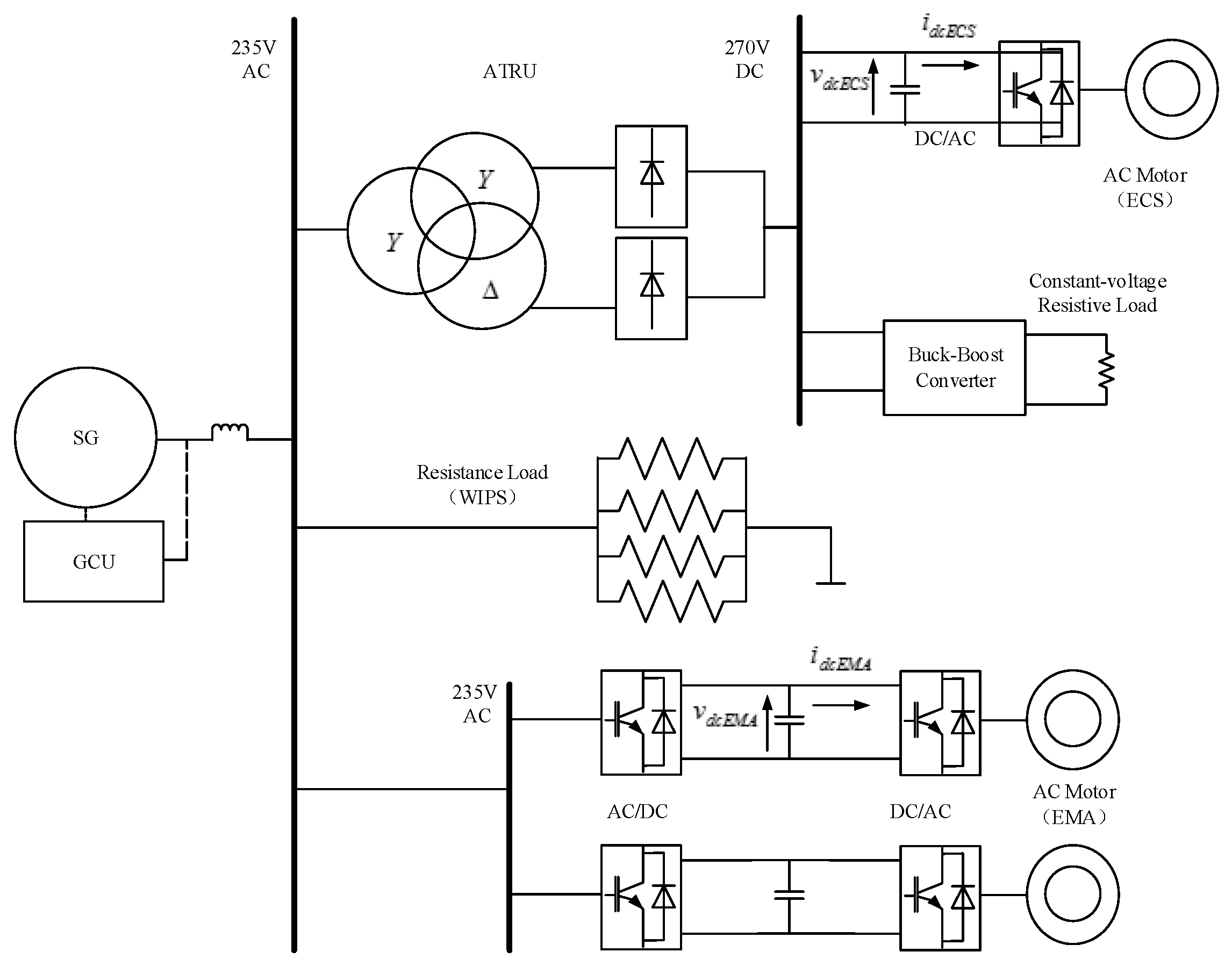
The typical structure of many electric aircraft power systems is shown in Figure 1. A synchronous variable frequency generator is connected to a 235 V high voltage alternating current (HVAC) bus and fed to the resistive load of the wing ice protection system (WIPS); The 270 V high voltage direct current (HVDC) bus is obtained from the HVAC bus by an Auto Transformer Rectifier unit (ATRU); The output of the ATRU provides electricity to the airborne electrical equipment, such as environmental control system (ECS) and speed-regulated motors driven by power electronics in the aircraft operating system, etc., through an R-L-C filter. In addition, the resistive load with constant voltage can also be connected to the HVDC bus.
With the development of power electronics technology, the scale of electric aircraft power systems is becoming larger and larger, and loads are becoming more and more complicated, which brings difficulty in modeling and stability analysis of aircraft power systems. Therefore, it is necessary to make a simplify aircraft power systems, reasonably and appropriately, so as to establish a unified large signal model for stability analysis.
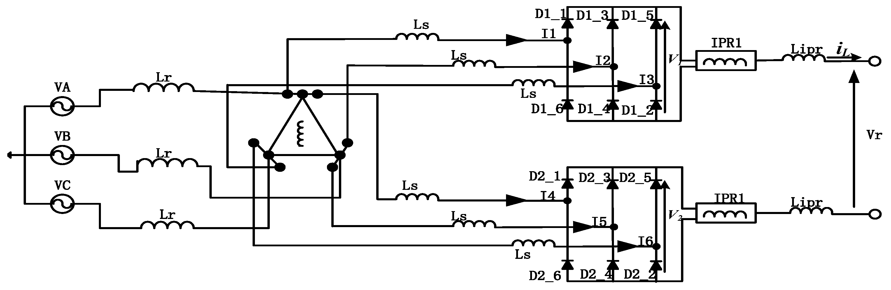
The 12-pulse autotransformer rectifier is firstly modeled and simplified by the AVM, for among the various components of an aircraft power system, the circuit structure is relatively complex. Then generator and relevant loads are equalized to obtain the unified large signal model of the aircraft power system. A schematic diagram of a 12-pulse autotransformer rectifier is shown in Figure 2.
The AC power supply consists of three balanced voltage sources; and the line-to-neutral voltages are expressed by the vector vn:
The phase shifting device produces two sets of three phase voltages with a phase difference of 30°, the two six-pulse rectifiers are parallel-connected to feed the load via the DC-link filter. The three equal inductors Lr represent the primary leakage inductances and the inductances of supply lines, the secondary leakage inductances of the phase-shifting devices are represented by three equal inductors Ls in series with each of the inputs to the two rectifiers, Lipr represents the DC side inductance. The output voltages of two rectifiers V1, V2 may be expressed by Equation (2) [17]:
where and are vectors of the two rectifier input currents; A1, B1 and C1 are coefficient matrices, which depend on the type of transformer, circuit inductances and the analysis interval. The 12-pulse autotransformer rectifier output voltage Vr can be obtained by the average value of V1 and V2. Therefore, within a specific 30° intervals the rectifier output voltage Vr may be expressed generally as:
where iL is DC link current; A, B, C also are coefficient matrices; D depends on the connection of the bridge outputs and the arrangement of the inter-phase reactors. , the averaged overall output voltage of Vr, is determined by the integration of (3) over a 30° interval of , divided by time:
where is the local average rate of change of the DC link current, and . The DC link current at the start of the interval is assumed to be , the local average value, and during the interval the current is assumed to rise by . Assuming that the three phase input to the upper bridge leads the input to the lower one by 30°, the 30° averaging interval begins at when the load current starts to commutate from D1_1 to in D1_3 the upper bridge, and the interval ends at when the current commutation from D2_1 to D2_3 begins in the lower bridge. By substituting and the related parameters into Equation (4), the general expression for averaged output voltage of 12-pulse autotransformer rectifier becomes:
The 12-pulse autotransformer rectifier generally used in most electric aircraft produces two sets of three phase waveforms that are phase shifted by ±15° with respect to the AC supply [25]. The turns-ratio n:1 of autotransformer is 6.464:1. The values of and are and respectively, and the constant k is 0.5. The coefficient matrices A, B, C and D are:
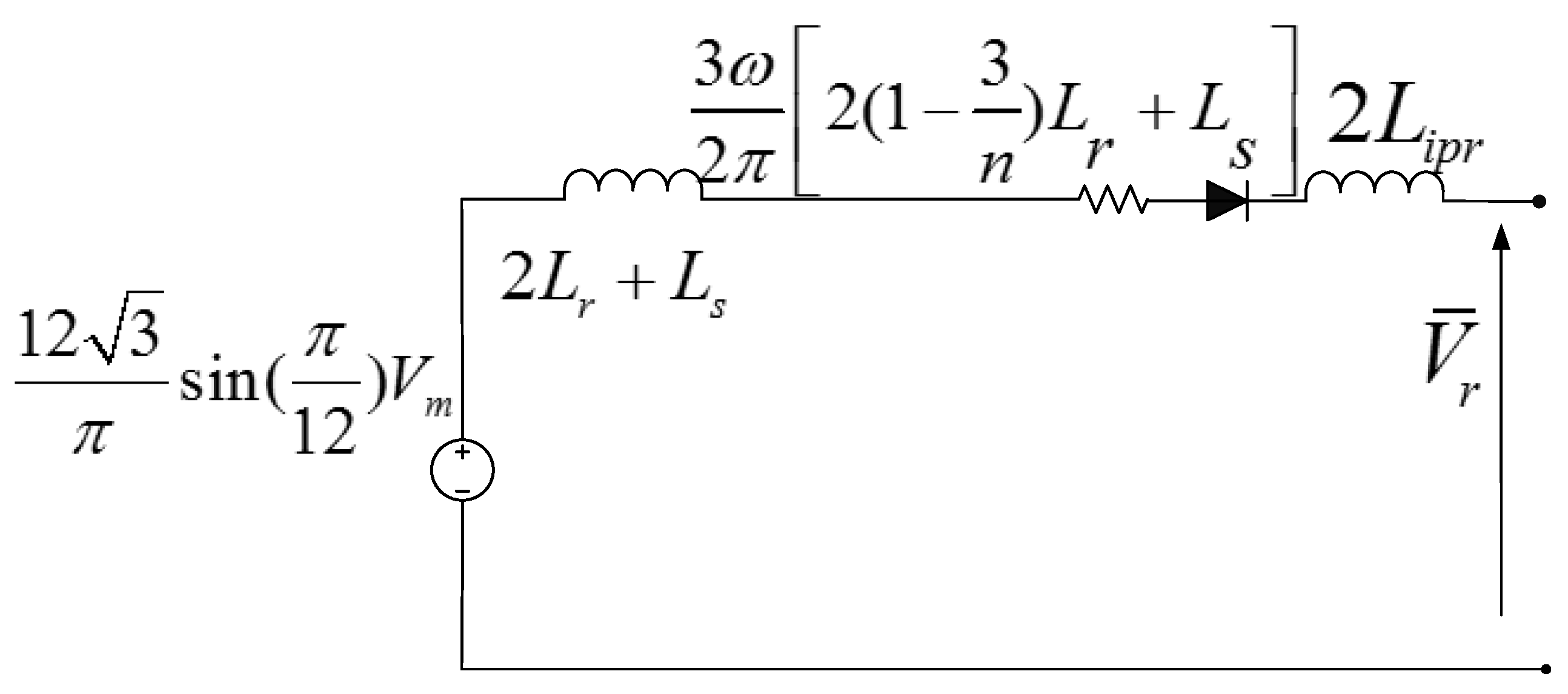
Therefore, the averaged output voltage of 12-pulse autotransformer rectifier is:
The simplified averaged model of 12-pulse autotransformer rectifier following Equation (7) is shown in Figure 3.
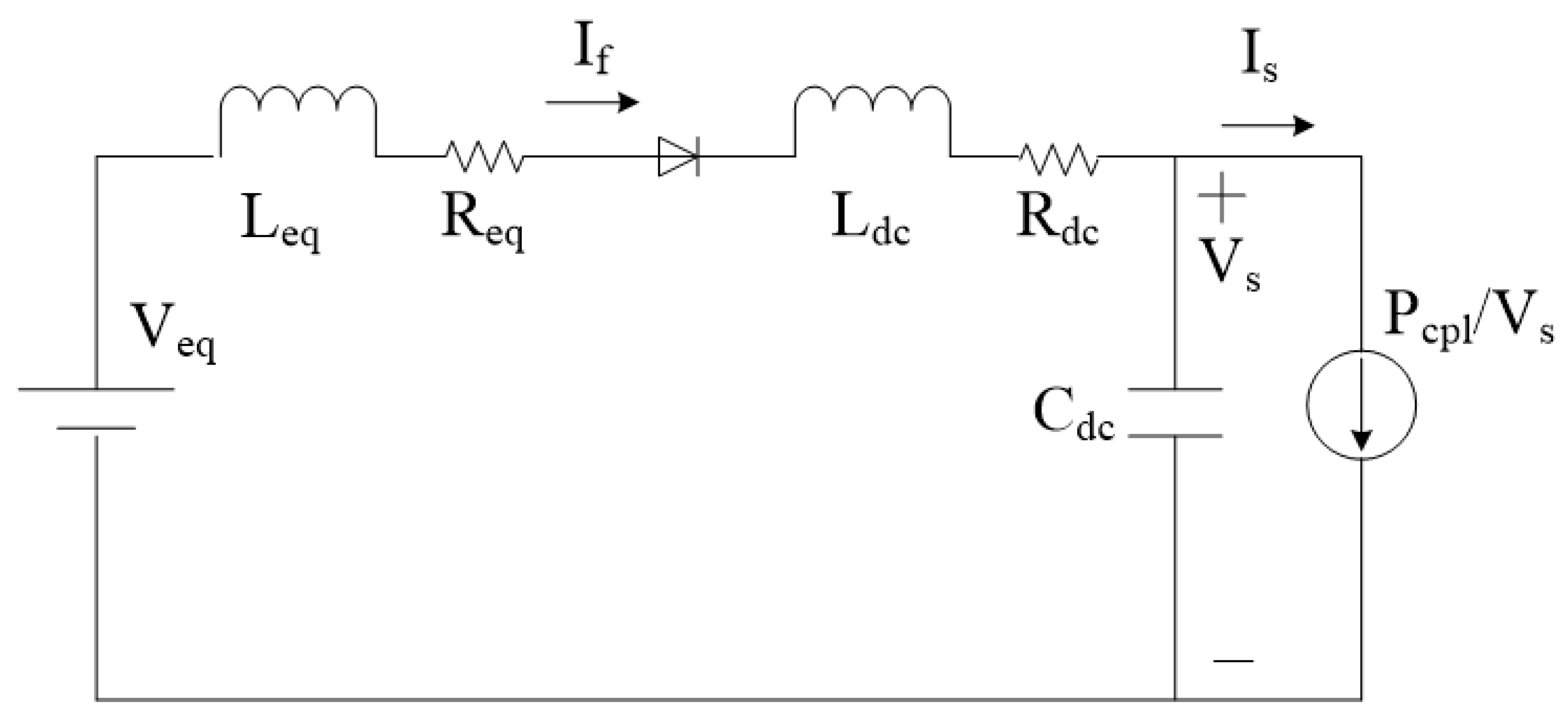
A generator can be equivalent to an ideal voltage source due to its good voltage control characteristics. The autotransformer rectifier uses the average model shown in Figure 3; the airborne electrical equipment driven by power electronic devices, such as AC speed regulating motors, can be regarded as constant power loads and represented by constant current sources; the voltage of HVAC bus is relatively stable, so the impact produced by AC resistive loads and speed regulating motors can also be neglected [26]. Therefore, the typical structure of an aircraft power system is rationally and appropriately simplified by the AVM, and the equivalent circuit for system stability analysis based on the unified large signal model is shown in Figure 4.
As shown in Figure 4, is the equivalent voltage source of AC power supply on DC side, where Vm is the amplitude of AC voltage. is the equivalent inductance in the DC side by the primary and secondary leakage inductances of the autotransformer and the line inductance. is the DC side equivalent resistance considering the commutation overlap angle of rectifier, . Ldc, Rdc and Cdc are the parameters of DC side filter, Vs is the voltage across the DC link capacitor Cdc and the loads are represented as a constant-power load Pcpl.
3. Stability Criterion of Aircraft Power Systems Based on the Unified Large Signal Model
The power system of more electric aircraft is a complex time-varying nonlinear system; the method of linearizing at the equilibrium point can only be used to analyze small signal stability problems, and large signal analysis study methods are needed for large signal disturbances. In this paper, the stability criteria of small signal and large signal stability are solved by the Lyapunov linearization method and the mixed potential function theory, respectively.
3.1. Criterion for Small Signal Stability
The Lyapunov linearization method judges small signal stability of a system according to the characteristics of the roots of its state equations [23]. For a linear time-invariant system, stability can be judged just by the roots of its eigenvalue equation. However, for nonlinear system such as aircraft power system, it must be linearized firstly, and then stability can be judged by the roots of the linearized eigenvalue equation. According to the equivalent circuit shown in Figure 4, set the state variables:
input variables:
and output variables:
Then, applying Kirchhoff’s Voltage Law (KVL) and Kirchhoff’s Circuit Laws (KCL), the following equations in state space are derived:
where , .
Equation (11) is linearized using the first order terms of the Taylor expansion so as to obtain a set of linear differential equations around an equilibrium point. We get:
where , , , align , and .
In the matrix , .
Based on the Jacobian matrix , the eigenvalue equation of aircraft power system is:
According to the Lyapunov linearization method, to ensure that the system is asymptotically stable at the equilibrium point, the real part of all eigenvalues of the Jacobian matrix must be negative. i.e.,
where (n—the number of state variables).
By Viete theorem, Let , the criterion for small signal stability of aircraft power system is:
3.2. Criterion for Large Signal Stability
For circuit systems containing nonlinear inductance, capacitance, resistance and other components, the large disturbance stability can be studied by constructing a global Lyapunov energy function and combining the stability judgment theorem of mixed potential function theory [27,28].
The mixed potential function P can be obtained by the components in a circuit and their topological relations, which general mixed potential function is:
where i, v are the inductance current and capacitor voltage of the equivalent circuit, respectively; and are potential functions for the circuit’s currents and voltages, respectively; is the energy of capacitor and some non-energy storage elements in the circuit, and is a constant matrix related to the circuit topology.
Here the third stability theorem [29] in mixed potential function theory is re-described for the convenience of application:
Let , and , . The Lyapunov energy function can be constructed as:
where L and C are the diagonal matrix of inductance and capacitor components within the circuit, respectively; u1 and u2 are the minimum eigenvalue of and , respectively.
According to the equivalent circuit of the unified large signal model shown in Figure 4, the potential functions of currents and voltages of non-energy-storage elements are:
The mixed potential function of the aircraft power system is given by:
Combining the stability definition of mixed potential function, we can get:
Both and are first-order matrix, due to the equivalent inductance and capacitance are represented by only one inductor Lf and one capacitor Cdc in the equivalent circuit, and their minimum eigenvalue u1 and u2 are:
By (17) and (20), the global Lyapunov energy function of system can be obtained as:
According to the stability theory of mixed potential function [23], for all if and vs belong to some region, if:
and when , then all the solutions of the system will tend to steady operating point, and the system can finally run stably.
From Equations (23), (24) and (26), the criterion for large signal stability of aircraft power system under unified large signal model can be obtained as:
3.3. Unified Criterion for Large and Small Signal Stability
In order to ensure that Equation (27) can be satisfied continuously during a large signal disturbance, the critical minimum Vsmin that output voltage Vs may reach should be taken into account. Therefore, the Equation (27) can be rewritten as:
Alignment of the constraints of Equations (15) and (28) indicates that, since the critical minimum Vsmin of the system output voltage during the disturbance process is less than the rated output voltage Vs,0, the criterion for large signal stability (Equation (28)) covers the criterion for small signal stability (Equation (15)). That is, the system parameters must meet more stringent conditions if the aircraft power system is to remain stable under larger signal disturbances as compared to small signal disturbances. On the other hand, it is also proved that the stability of aircraft power systems under small signal disturbance doesn’t represent the stability under large signal disturbance.
Hence, based on the unified large signal model of aircraft power system, shown in Figure 4, the stability criterion shown in Equation (28) is suitable for both large and small signal stability analysis. The aircraft power system is able to remain stable under either small or large signal disturbances as long as the inequality (28) is satisfied. The combination of two stability criteria helps to further simplify the analysis process of aircraft power system.
4. Simulation Verification
This paper tries to verify the reliability of the unified criterion for large and small signal stability derived from the unified large signal model established by the AVM. A detailed simulation experiment is implemented by the MATLAB and simulation results are compared with the theoretical calculation results. Meanwhile, by taking a permanent magnet synchronous motor (PMSM) as load, a large signal disturbance experiment of short-circuit fault is carried out to further verify the accuracy of the unified large signal model.
4.1. Validation of the Stability Criterion
The equivalent circuit of the unified large signal model of aircraft power system shown in Figure 4 is used as an experimental object, which parameters are shown in Table 1.
For analysis of small signal stability, the eigenvalues of the system are calculated from the matrix in Equation (12). The eigenvalues plotted by slowly changing Pcpl from 0.5 kW to 4.0 kW is shown in Figure 5.
As can be seen from Figure 5, the eigenvalues of the power system are gradually shifting to the right when the size of constant power load is increasing slowly. In particular, the eigenvalue becomes 0 when power is increased to 3.535 kW, and the system is under a critical condition of stability according to the stability theorem of Lyapunov linearization method. Furthermore, if the load power increases continuously, the system will become unstable since the real part of eigenvalue becomes positive.
The large disturbance stability of aircraft power systems under load change is studied by adopting the mixed potential function theory and the simulation result as shown in Figure 6. It can be seen that the stability region of the system decreases as the load power step increases, and when the load power reaches about 3.2 kW, the stability domain tends to 0, i.e., the system will be in the critical stable state. Thus, the parameters of aircraft power system need to meet more stringent conditions to maintain stability under large signal disturbances, as compared with the parameters under small signal disturbances.
Figure 7 shows the time domain simulation result of the stability effect is caused by different load powers of an aircraft power system. It can be seen that the system couldn’t maintain stability when the constant power load increases to 3.6 kW, causing vibration and divergence of load voltage. Furthermore, the simulation results shown in Figure 5 and Figure 6 indicate that the stability region calculated by the Lyapunov linearization method and the mixed potential function theory is approximately consistent with the time domain simulation result within a certain range, verifying that the unified large signal model is viable and accurate for the stability analysis of aircraft power systems.
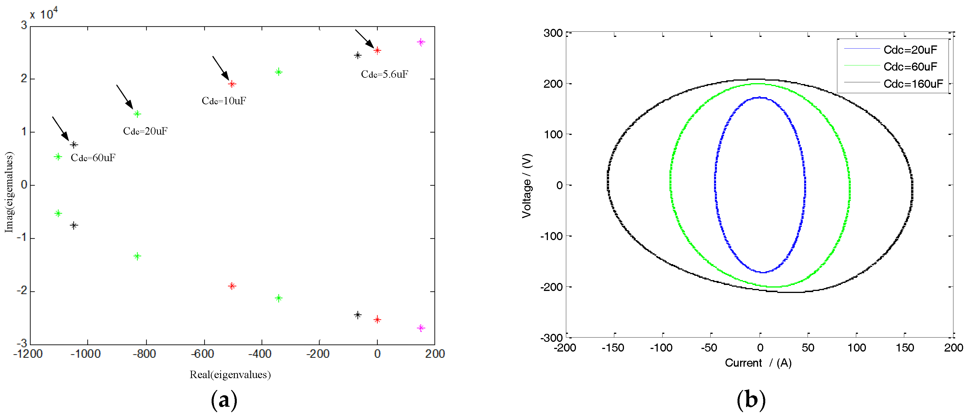
In addition, the use of the unified large signal model is still feasible to analyze the system’s stability when other disturbances occur in an aircraft power system. Figure 8 shows the stability results caused by the parameters of filter capacitance under small and large signal disturbances, respectively. It can be seen that the airborne power system based on the unified large signal model can be easily used to analyze the change of the system stability domain with the parameters, and the calculation process is simple and time-consuming.
4.2. Simulation Example of Large Signal Disturbance
In an aircraft’s electro-mechanical actuator system, a short-circuit fault is a common large signal disturbance. In this paper, taking a PMSM as a load of the unified large signal model, a simulation experiment is carried out. The load model of PMSM is shown in Figure 9, including inverter, PMSM and its controller.
The parameters of PMSM and its controller are shown in Table 2.
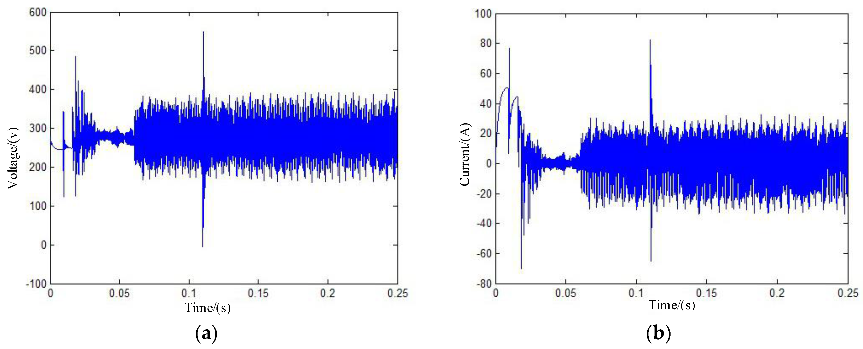
The simulation experiment of short circuit fault in the aircraft power system is implemented with the results shown in Figure 10.
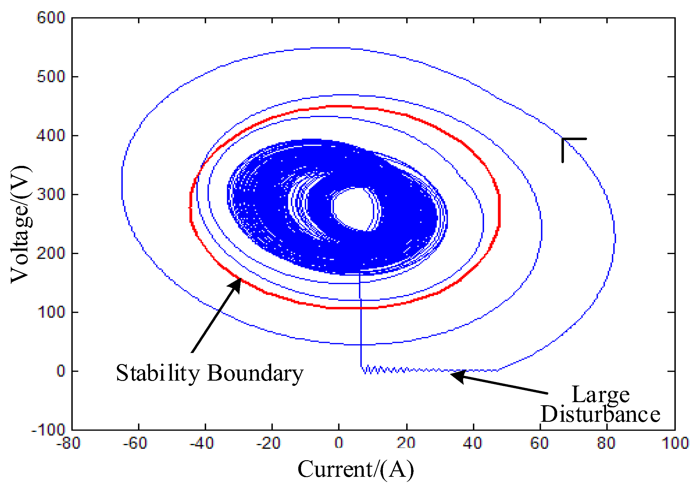
The simulation results in Figure 10 show that, the system is stable before the short-circuit fault occurs; the voltage suddenly drops to zero when the large disturbance of short-circuit fault occurs; and the system is restored to stability after the fault is removed. In addition, with the PMSM load model, the stability domain under large signal disturbance calculated by the mixed potential function theory is shown in Figure 11.
Figure 11 indicates that, the system’s stability domain boundary calculated by the mixed potential function theory covers a large range around the stable point, which can be used to evaluate the system’s ability of resisting large signal disturbance, direct the optimal design of system. It is further validated that the unified large signal model of aircraft power systems established in this paper is effective.
4.3. Discussion
Simulation results show that the proposed unified large signal model of aircraft power systems can generate about 1.8% of error when it is used to analyze small signal stability problems. In addition, the proposed unified large signal model yields about 13.3% of error when it is applied to deal with large signal stability problems. Therefore, within a certain error range, the proposed model can be used to deal with both small and large signal stability problems, even though it has smaller error when applied to solve small signal stability problems. Compared with [16], which generates about 1.5% of error when dealing with small signal stability problem, this method does however reduce the simulation accuracy:
- (1)
- The proposed method can not only be used to analyze small signal problem, but also to analyze large signal problems of aircraft power systems;
- (2)
- The proposed method successfully reduces the order of aircraft power system models by using a reasonable and appropriate equivalent. By doing that, aircraft power system models can be simplified. This has many potential benefits for the theoretical analysis of aircraft power system stability;
- (3)
- The proposed method avoids calculating complicated impedance in the process of solving the stability criterion; therefore, it reduces the amount of calculation work.
5. Conclusions
From the research perspective of large signals, this paper develops a unified large signal model of aircraft power systems based on the AVM, in which small and large signal stability are studied by the Lyapunov linearization method and the mixed potential function theory, respectively, obtaining a unified stability criterion of large and small signal disturbances.
Analysis and simulation results show that the unified large signal simplification model of aircraft power systems proposed in this paper can be effectively applied to analyze the stability of the systems when small or large disturbances occur.
The most remarkable advantage of the unified large signal model is that the large and small signal stability criteria of complex aircraft power systems are combined by constructing a reasonable and simplified model, which in turn simplifies the design process, avoids complicated and cumbersome calculations, and is able to quickly and accurately judge the stability of aircraft power systems. With simplicity, universality and structural uniformity, the model lays a good foundation for the stability analysis and the optimal design of aircraft power systems.
Acknowledgments
This work is sponsored by National Natural Science Foundation of China (No. U1533126). Authors would like to express their appreciation of the help offered by Yuancheng Zhao and Jinhuan Zhou.
Author Contributions
Yanbo Che converved and designed the study; Jianmei Xu derived the model of aircraft power system; Huanan Liu and Jianmei Xu calculated the stability criterion; Weihua Chen and Kun Shi conducted the simulation; Dongmin Yu wrote the paper and revised the paper.
Conflicts of Interest
The authors declare no conflict of interest.
References
- Sarlioglu, B.; Morris, C.T. More electric aircraft: Review, challenges, and opportunities for commercial transport aircraft. IEEE Trans. Transp. Electrification 2015, 1, 54–64. [Google Scholar] [CrossRef]
- Wheeler, P.; Bozhko, S. The more electric aircraft: Technology and challenges. IEEE Electrification Mag. 2014, 2, 6–12. [Google Scholar] [CrossRef]
- Rajashekara, K. Parallel between more electric aircraft and electric/hybrid vehicle power conversion technologies. IEEE Electrification Mag. 2014, 2, 50–60. [Google Scholar] [CrossRef]
- Sarlioglu, B. Advances in AC-DC power conversion topologies for More Electric Aircraft. In Proceedings of the 2012 IEEE Transportation Electrification Conference and Expo (ITEC), Dearborn, MI, USA, 18–20 June 2012; pp. 1–6. [Google Scholar] [CrossRef]
- Yan, Y.G.; Qin, H.H.; Gong, C.Y.; Wang, H.Z. More electric aircraft and power eiectronics. J. Nanjing Univ. Aeronaut. Astronaut. 2014, 46, 11–18. [Google Scholar] [CrossRef]
- Bennett, J.W.; Mecrow, B.C.; Atkinson, D.J.; Atkinson, G.J. Safety-critical design of electromechanical actuation systems in commercial aircraft. IET Electr. Power Appl. 2011, 5, 37–47. [Google Scholar] [CrossRef]
- Garcia, A.; Cusido, I.; Rosero, J.A.; Ortega, J.A.; Romeral, L. Reliable electro-mechanical actuators in aircraft. IEEE Aerosp. Electron. Syst. Mag. 2008, 23, 19–25. [Google Scholar] [CrossRef]
- Rottach, M.; Gerada, C.; Wheeler, P.W. Design optimisation of a fault-tolerant PM motor drive for an aerospace actuation application. In Proceedings of the IET International Conference on Power Electronics, Machines and Drives, Manchester, UK, 8–10 April 2014; p. 0472. [Google Scholar] [CrossRef]
- Lee, J.Y.; Jeong, Y.S.; Han, B.M. An Isolated DC/DC converter using high-frequency unregulated, $LLC$ resonant converter for fuel cell applications. IEEE Trans. Ind. Electron. 2011, 58, 2926–2934. [Google Scholar] [CrossRef]
- Rivetta, C.; Williamson, G.A.; Emadi, A. Constant power loads and negative impedance instability in sea and undersea vehicles: Statement of the problem and comprehensive large-signal solution. In Proceedings of the IEEE Electric Ship Technologies Symposium, Philadelphia, PA, USA, 27 July 2005; pp. 313–320. [Google Scholar] [CrossRef]
- Wu, C.; Si, G.; Zhang, Y.; Yang, N. The fractional-order state-space averaging modeling of the Buck–Boost DC/DC converter in discontinuous conduction mode and the performance analysis. Nonlinear Dyn. 2015, 79, 689–703. [Google Scholar] [CrossRef]
- Emadi, A. Modelling of power electronic loads in AC distribution systems using the generalized state space averaging method. IEEE Trans. Ind. Electron. 2004, 51, 992–1000. [Google Scholar] [CrossRef]
- Che, Y.; Liu, G.; Yang, Z.; Liu, X. Model of inverter in more electric aircraft based on generalized state space averaging approach. In Proceedings of the 2015 6th International Conference on Power Electronics Systems and Applications (PESA), Hong Kong, China, 15–17 December 2015; pp. 1–5. [Google Scholar] [CrossRef]
- Cao, W.; Ma, Y.; Yang, L.; Wang, F.; Tolbert, L.M. D–Q impedance based stability analysis and parameter design of three-phase inverter-based AC power systems. IEEE Trans. Ind. Electron. 2017, 64, 6017–6028. [Google Scholar] [CrossRef]
- Han, S.B.; Choi, N.S.; Rim, C.T.; Cho, G.H. Modeling and analysis of static and dynamic characteristics for buck-type three-phase PWM rectifier by circuit DQ transformation. IEEE Trans. Power Electron. 1998, 13, 323–336. [Google Scholar] [CrossRef]
- Areerak, K.N.; Bozhko, S.V.; Asher, G.M.; Thomas, D.W.P. Stability analysis and modelling of AC-DC system with mixed load using DQ-transformation method. In Proceedings of the IEEE International Symposium on Industrial Electronics, Cambridge, UK, 30 June–2 July 2008; pp. 19–24. [Google Scholar] [CrossRef]
- Baghramian, A.; Forsyth, A.J. Averaged-value models of twelve-pulse rectifiers for aerospace applications. In Proceedings of the Second International Conference on Power Electronics, Machines and Drives, Edinburgh, UK, 31 March–2 April 2004; Volume 1, pp. 220–225. [Google Scholar] [CrossRef]
- Jadric, I.; Borojevic, D.; Jadric, M. Modeling and control of a synchronous generator with an active DC load. IEEE Trans. Power Electron. 2000, 15, 303–311. [Google Scholar] [CrossRef]
- Liutanakul, P.; Pierfederici, S.; Bilal, A.; Nahid-Mobarakeh, B.; Meibody-Tabar, F. Stability investigation of inverter motor drive system with input filter—Optimisation of the DC-link capacitance value. In Proceedings of the 2008 IEEE Power Electronics Specialists Conference, Rhodes, Greece, 15–19 June 2008; pp. 3728–3734. [Google Scholar] [CrossRef]
- Zhu, H.; Burgos, R.P.; Lacaux, F.; Uan-Zo-li, A.; Lindner, D.K.; Wang, F.; Boroyevich, D. Average modeling of three-phase and nine-phase diode rectifiers with improved AC current and DC voltage dynamics. In Proceedings of the 31st Annual Conference of IEEE Industrial Electronics Society, Raleigh, NC, USA, 6–10 November 2005; p. 6. [Google Scholar] [CrossRef]
- Han, L.; Wang, J.; Howe, D. Small-signal Stability Studies of a 270 V DC more-electric aircraft power system. In Proceedings of the 2006 3rd IET International Conference on Power Electronics, Machines and Drives, Dublin, Ireland, 4–6 April 2006; pp. 162–166. [Google Scholar] [CrossRef]
- Areerak, K.N.; Bozhko, S.V.; Asher, G.M.; De Lillo, L.; Thomas, D.W.P. Stability study for a hybrid AC-DC more-electric aircraft power system. IEEE Trans. Aerosp. Electron. Syst. 2012, 48, 329–347. [Google Scholar] [CrossRef]
- Du, W. Research on Key Aspects in Large-Signal Stability Analysis for Current Mode Controlled DC-DC Cascaded System; Zhejiang University: Hangzhou, China, 2013. [Google Scholar]
- Griffo, A.; Wang, J.; Howe, D. Large signal stability analysis of DC power systems with constant power loads. In Proceedings of the 2008 IEEE Vehicle Power and Propulsion Conference, Harbin, China, 3–5 September 2008; pp. 1–6. [Google Scholar] [CrossRef]
- Choi, S.; Enjeti, P.N.; Pitel, I.J. Polyphase transformer arrangements with reduced kVA capacities for harmonic current reduction in rectifier-type utility interface. IEEE Trans. Power Electron. 2002, 11, 680–690. [Google Scholar] [CrossRef]
- Griffo, A.; Wang, J. Large signal stability analysis of ‘More Electric’ aircraft power systems with constant power loads. IEEE Trans. Aerosp. Electron. Syst. 2012, 48, 477–489. [Google Scholar] [CrossRef]
- Jeltsema, D.; Scherpen, J.M.A. On Brayton and Moser’s missing stability theorem. IEEE Trans. Circuits Syst. II 2005, 52, 550–552. [Google Scholar] [CrossRef]
- Weiss, L.; Mathis, W.; Trajkovic, L. A generalization of Brayton-Moser’s mixed potential function. IEEE Trans. Circuits Syst. I 1998, 45, 423–427. [Google Scholar] [CrossRef]
- Liu, X.; Zhou, Y. Large signal stability criteria for constant power loads with double-stage LC filters. Proc. CSEE 2011, 31, 29–35. [Google Scholar] [CrossRef]
Figure 1.
Typical structure of most electric aircraft.

Figure 2.
Schematic of autotransformer based 12-pulse rectifier.

Figure 3.
Average value model of 12-pulse autotransformer.

Figure 4.
The equivalent circuit based on a unified large signal model.

Figure 5.
Eigenvalue plot of system.
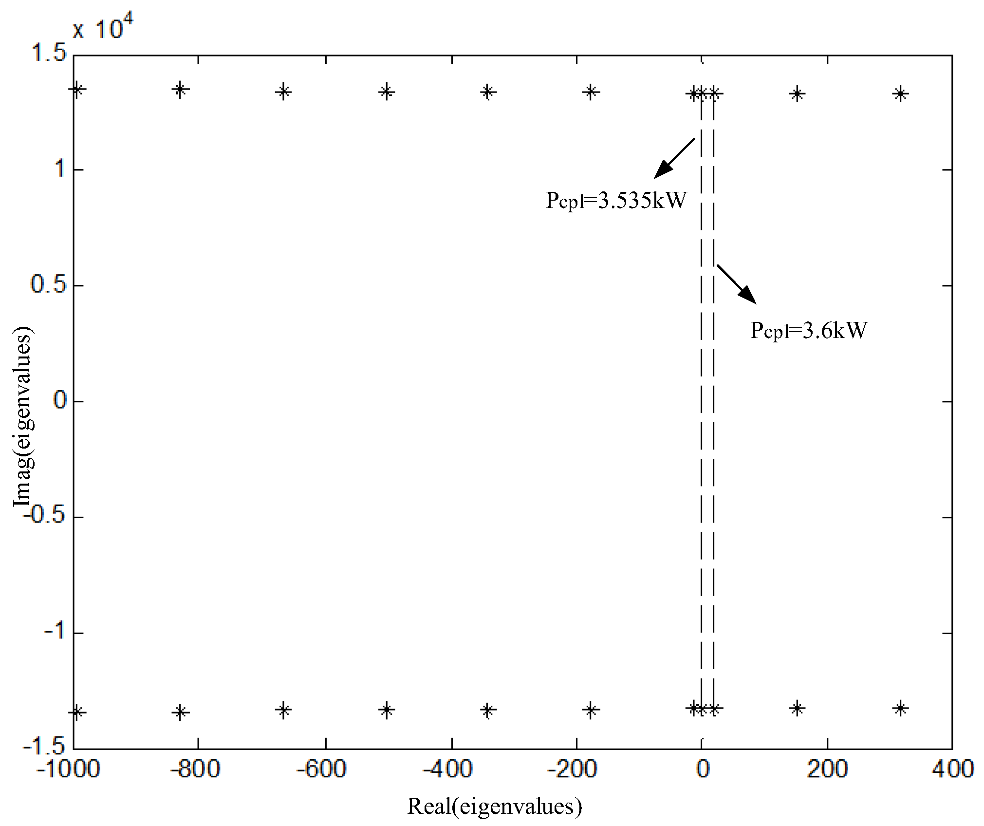
Figure 6.
Changes in system stability region.

Figure 7.
Time domain simulation results of system stability influenced by different power levels.
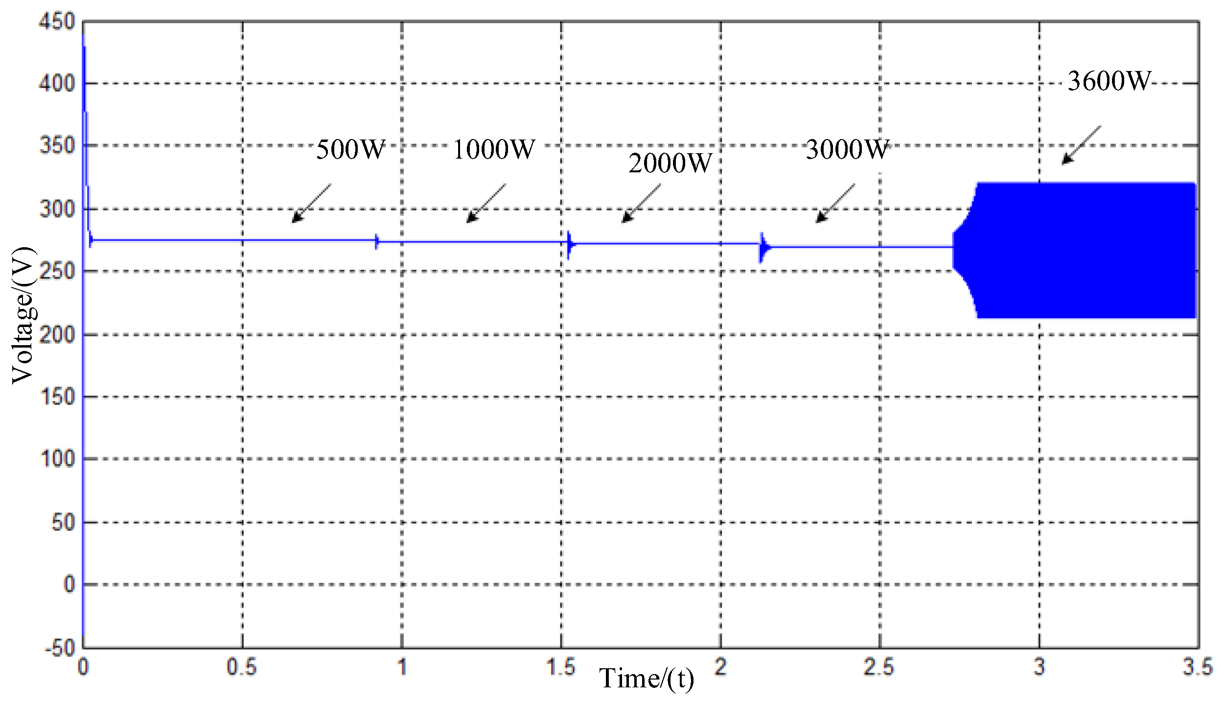
Figure 8.
Influence of different filter capacitor parameters on system stability: (a) small signal stability; (b) large signal stability.
Figure 8.
Influence of different filter capacitor parameters on system stability: (a) small signal stability; (b) large signal stability.

Figure 9.
Simulation schematic based on PMSM.
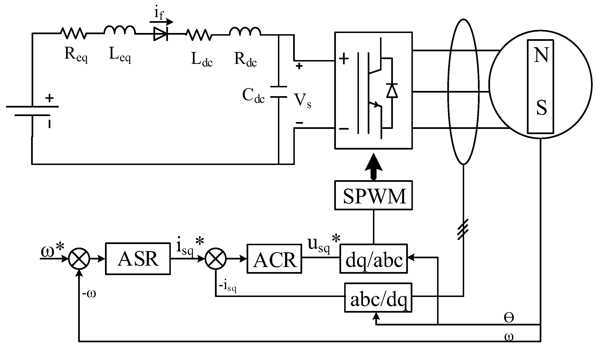
Figure 10.
Large disturbance simulation experiment with PMSM load (P = 0.5 kW): (a) Voltage fluctuation; (b) Current fluctuation.
Figure 10.
Large disturbance simulation experiment with PMSM load (P = 0.5 kW): (a) Voltage fluctuation; (b) Current fluctuation.

Figure 11.
Large disturbance stability domain based on PMSM.


Table 1.
Simulation parameters of aircraft power system.
| Parameter | Value | Parameter | Value |
|---|---|---|---|
| Vm | 162/V | Ldc | 50/uH |
| f | 400/Hz | Cdc | 20–160/uF |
| Lp | 30/uH | Rdc | 0.5/Ω |
| Ls | 80/uH | Pcpl | 0.5–4.0/kW |
Table 2.
Simulation parameters of PMSM.
| Parameter | Value | Parameter | Value |
|---|---|---|---|
| Stator resistance | 2.875/Ω | Rotational inertia | 0.008/kg·m2 |
| Exciting flux | 0.175/Wb | Pole-pairs number | 1 |
| Stator d-axis inductance | 0.0085/uH | Speed regulator Kp/Ki | 11.7/140 |
| Stator q-axis inductance | 0.0085/uH | Current regulator Kp/Ki | 10.7/80 |
© 2017 by the authors. Licensee MDPI, Basel, Switzerland. This article is an open access article distributed under the terms and conditions of the Creative Commons Attribution (CC BY) license (http://creativecommons.org/licenses/by/4.0/).
Share and Cite
MDPI and ACS Style
Che, Y.; Xu, J.; Shi, K.; Liu, H.; Chen, W.; Yu, D. Stability Analysis of Aircraft Power Systems Based on a Unified Large Signal Model. Energies 2017, 10, 1739. https://doi.org/10.3390/en10111739
AMA Style
Che Y, Xu J, Shi K, Liu H, Chen W, Yu D. Stability Analysis of Aircraft Power Systems Based on a Unified Large Signal Model. Energies. 2017; 10(11):1739. https://doi.org/10.3390/en10111739
Chicago/Turabian StyleChe, Yanbo, Jianmei Xu, Kun Shi, Huanan Liu, Weihua Chen, and Dongmin Yu. 2017. "Stability Analysis of Aircraft Power Systems Based on a Unified Large Signal Model" Energies 10, no. 11: 1739. https://doi.org/10.3390/en10111739
Note that from the first issue of 2016, this journal uses article numbers instead of page numbers. See further details here.