A Review on the Recent Development of Capacitive Wireless Power Transfer Technology


Department of Electrical and Computer Engineering, San Diego State University, San Diego, CA 92182, USA
*
Author to whom correspondence should be addressed.
Energies 2017, 10(11), 1752; https://doi.org/10.3390/en10111752
Submission received: 17 October 2017
/
Revised: 30 October 2017
/
Accepted: 30 October 2017
/
Published: 1 November 2017
(This article belongs to the Special Issue Wireless Power Transfer and Energy Harvesting Technologies)
Abstract
:Capacitive power transfer (CPT) technology is an effective and important alternative to the conventional inductive power transfer (IPT). It utilizes high-frequency electric fields to transfer electric power, which has three distinguishing advantages: negligible eddy-current loss, relatively low cost and weight, and excellent misalignment performance. In recent years, the power level and efficiency of CPT systems has been significantly improved and has reached the power level suitable for electric vehicle charging applications. This paper reviews the latest developments in CPT technology, focusing on two key technologies: the compensation circuit topology and the capacitive coupler structure. The comparison with the IPT system and some critical issues in practical applications are also discussed. Based on these analyses, the future research direction can be developed and the applications of the CPT technology can be promoted.
1. Introduction
Wireless power transfer (WPT) technology utilizes energy-contained fields to deliver electric power from the transmitter to the receiver side, removing the direct metal-to-metal contact [1,2,3,4]. The typical structure of a WPT system is shown in Figure 1.
At the primary side, an auxiliary circuit is usually required to convert the electric power into a proper form to excite the transmitter device, which can generate the corresponding fields and transmit to the secondary side. In the power transmission process, a medium is not always required, but its appearance usually contributes to improve the system performance. At the secondary side, the receiver device can convert the fields back into electric power and provide it to the load through another auxiliary circuit.
According to the category of fields, the current WPT systems can be classified into acoustic power transfer (APT) [5,6,7], optical power transfer (OPT) [8], microwave power transfer (MPT) [9], inductive power transfer (IPT) [10], and capacitive power transfer (CPT) [11], as shown in Figure 2, which are suitable for different applications.
Among all the power transfer systems, the CPT technology has been widely studied in recent years. The typical structure of a CPT system is shown in Figure 3.
The CPT system in Figure 3 is also a practical implementation of the WPT system in Figure 1. The auxiliary circuits are realized by power electronics converters and the corresponding compensation networks, including inductors and capacitors. The transmitter and receiver are realized by metal plates. Usually, four metal plates are required in a CPT system to form a capacitive coupler. Two plates are used at the primary side as a power transmitter, and the other two plates at the secondary side act as a power receiver, resulting in at least two coupling capacitors to provide a power flow loop.
Different CPT systems can be realized by different coupler structures. For example, in Figure 3, since there are two pairs of plates in the coupler, it is also called a bipolar structure. In some other applications, one pair of plates can be realized by the stray capacitance from a receiver terminal to a transmitter terminal, resulting in a unipolar structure that is similar to a single-wire system [12]. The value of coupling capacitance depends on the plate area, distance, and the dielectric material between the plates. Since the permittivity constant ε0 of air is as small as 8.85 × 10⁻¹² F/m, the value of coupling capacitance is limited. Therefore, it usually requires resonances in the circuit between the compensation networks and the coupler, producing high voltages on the plate to generate sufficient electric fields for power transfer.
The advantages of the CPT technology lie in its low cost, low weight, and low eddy-current loss in nearby metals [13]. According to recent studies, it can be used in short distance and low power applications, such as integrated circuits (IC) [14], biomedical devices [15,16], LED lighting [17,18], USB and mobile device charging [19,20,21]. In addition, its power can be increased to kW level and applied to high power areas, such as synchronous machine excitation [22,23,24]. As a duality to inductive machine, the Lorentz force in a CPT system can be used to realize an electrostatic rotating machine for motor driving [25,26]. Moreover, the transfer distance and power can be further increased to charge the electric vehicles, or even realize dynamic charging while the vehicle is moving along the roadway [27,28,29,30]. Based on these developments, this paper will review all the latest progresses in the CPT technology, especially for the long-distance and high-power electric vehicle charging applications. The theoretical analysis and detailed implementations will be presented, aiming to promote the practical applications of the CPT technology.
2. Fundamental Working Principle
2.1. General Mathematical Model of CPT System
To analyze its fundamental working principle, the structure of a CPT system can be further simplified as the circuit topology in Figure 4.
The input and output sides are represented by two sinusoidal sources V1 and V2, neglecting the high-order harmonics in the circuit. The input and output side currents are defined as I1 and I2, respectively. The capacitive coupler acts as a two-port network for the primary and secondary sides. Generally, the capacitive coupler can be represented by its equivalent behavior source model, including two capacitors and two voltage-controlled current sources, as provided in [31]. In a capacitive coupler, there are multiple coupling capacitances between plates, which can increase the complexity of the working principle analysis. Therefore, it needs to be simplified as an equivalent mutual capacitance CM and two equivalent internal self-capacitances Cin1 and Cin2, as shown in Figure 4. The simplification process and definitions of the equivalent capacitances will be provided in Section 4 in this paper.
In Figure 4, the capacitive coupling between the primary and secondary sides is represented by two voltage-controlled current sources IM1 and IM2, where IM1 is used to transfer power and IM2 is used to receive power [32]. Therefore, the apparent power SM1 absorbed by IM1 is expressed as
where the asterisk notation means the complex conjugate; SM1 is a complex power, including real and imaginary part defined as PM1 and QM1, respectively; VC1 and VC2 are the voltages across the primary and secondary capacitance Cin1 and Cin2; ω is the angular switching frequency of the input and output sources. The primary voltage VC1 is selected as the reference phasor, and the phase difference of VC2 is defined as θ, resulting in
According to Equation (2), the apparent power SM1 is further expressed as
Therefore, the active and reactive power absorbed by the current source IM1 is expressed as
At the receiver side, the apparent power SM2 that provided by the secondary current source IM2 is expressed as
Similarly, the real and imaginary part of SM2 is defined as PM2 and QM2, respectively. Then, the apparent power SM2 is further expressed as
Therefore, the active and reactive power provided by the current source IM2 is expressed as
Comparing Equations (1) and (5), the magnitude of apparent power can be expressed as |SM|=|SM2|=|SM1|. In addition, comparing Equations (3) and (6), it shows that the active power absorbed by IM1 is equal to the active power provided by IM2, which is consistent with the universal energy conservation law. Then, the active power is further defined as PM = PM1 = PM2. It also needs to be emphasized that the reactive power QM1 absorbed by IM1 does not equal to the reactive power provided by QM2, but they are opposite to each other. Then, the reactive power is further defined as QM = QM1 = −QM2. To summarize, the apparent power SM can be illustrated in Figure 5, where the x-axis is the reactive power and y-axis is the active power.
Figure 5 shows that, when θ is in the range of (0°, 180°), there is PM1 > 0, which means active power is transferred from the primary to secondary side. When θ is in the range of (−180°, 0°), there is PM1 < 0 and the power transfer direction is reversed. In a CPT system design process, the active power PM is usually known to satisfy the power requirement. Then, the corresponding reactive power QM is expressed as
Figure 6 shows that the reactive power QM relates to the phase angle θ between VC1 and VC2. For example, when θ = 90°, QM = 0, which means there is no reactive power transferred to the secondary side. When θ = 45°, QM = PM, which means the transferred reactive power is equal to the active power. When θ approaches to 0°, the reactive power QM is dramatically increased to be much larger than the active power PM.
According to Equations (4) and (7), when the required active power PM is known, increasing sinθ can help reduce the voltages |VC1| and |VC2|. Therefore, in a practical system design, the phase angle θ can be designed to be close to 90°. In this way, the reactive power circulating in the circuit is reduced to almost zero, and the corresponding conduction loss is also minimized. It needs to be clarified that the phase angle θ can be adjusted through compensation circuit design, which will be presented in Section 3.
Meanwhile, Equations (4) and (7) also show that the system power is proportional to the switching frequency ω, the mutual coupling capacitance CM, and the voltages |VC1| and |VC2| on the metal plates. In a CPT system, these values can be increased to achieve high power transfer. The parameter sinθ can be designed to be 1.0 to maximize the system power. As an example, the coupling capacitance CM is 10pF, the maximum achievable system power PM at different switching frequency fs (fs = ω/2π), and the plate voltage |VC1| is shown in Figure 7. In this analysis, it is assumed that |VC1| = |VC2| for simplification purpose.
Figure 7 shows that the magnitude of the plate voltage |VC1| needs to be increased to kV level to achieve kW power transfer. For example, in a vehicle charging application, when fs is 1 MHz, 3 kW system power requires |VC1| to be 7 kV. This high voltage can induce potential safety issues in a practical application, which will be discussed in Section 6. Theoretically, according to Equations (4) and (7), the CPT technology can also be used in an extremely high power system. For example, the plate voltage |VC1| at different CM, and fs of a 200 kW CPT system is shown in Figure 8. Similarly, it is assumed sinθ = 1 and |VC1| = |VC2|.
Increasing the switching frequency fs is an effective way to acquire higher power. With limited coupling capacitance CM, fs needs to be increased to 10s of MHz to achieve 10s or even 100s of kW power transfer. The high frequency and high power working condition usually require wide bandgap (WBG) power electronics devices, such as silicon carbide (SiC) and gallium nitride (GaN) MOSFETs, to build up the power converters.
2.2. Maximum Achievable Efficiency of a CPT System
The previous section presented the system power property for an ideal CPT system where the losses are neglected. However, the efficiency property is also an important concern. Especially in a long-distance and loosely-coupled CPT system, it is meaningful to study its efficiency to maintain effective power transfer. Since the coupling capacitance CM is limited, it is necessary to increase the plate voltage for sufficient power transfer. Auxiliary circuits, either resonant or non-resonant, are required to work with the capacitive coupler. According to Figure 4, its equivalent circuit is shown in Figure 9 for efficiency analysis. This equivalent circuit can be realized by multiple methods, resulting in different compensation circuit topologies, which will be discussed in Section 3.
Comparing Figure 4 and Figure 9, the external capacitances Cex1 and Cex2 in the compensation networks are combined with the internal capacitances Cin1 and Cin2 of the capacitive coupler, resulting in an equivalent capacitive coupler with C1 = Cin1 + Cex1 and C2 = Cin2 + Cex2. The capacitive coupling coefficient kC is further defined as
Then, two inductive networks are used at both the primary and secondary sides to form resonances with the capacitances. The output voltage source V2 is represented by a resistive load RL to analyze the system efficiency. Considering the power losses of the resonant circuit components, Figure 9 is further simplified as Figure 10.
In Figure 10, the input source V1 is represented by an equivalent source V1eq, and the output load RL is represented by an equivalent conductance GLeq. The power losses of the capacitances are represented by parallel-connected conductances GC1 and GC2. The inductive networks in Figure 9 are represented by two equivalent inductances L1 and L2, and their power losses are also represented by two parallel-connected conductances GL1 and GL2, respectively. It needs to be emphasized that the derivation of the equivalent inductances is a simplification of the inductive networks. Regardless of the complexity of the inductive networks, they can be simplified as equivalent inductances with their losses, which mean this analysis is independent of the circuit topology [33,34,35].
Generally, at both the primary and secondary sides, the matching networks are designed to compensate the impedance of the capacitive coupler. To eliminate the reactive power circulating in the circuit and maximize the system efficiency, L1 and L2 need to be designed to perfectly resonate with C1 and C2, respectively. In this way, the secondary side voltage VC2 is expressed as
By substituting Equation (12) into Equation (10), the system efficiency is rewritten as
By substituting Equation (9) into Equation (13), the efficiency is simplified as
where α is defined as load ratio, and Q1 and Q2 are defined as the quality factor of the primary and secondary circuit, respectively. It needs to be clarified that Q1 and Q2 have included the power losses in both the capacitors and inductors. They can be expressed as
Equation (14) shows that the system efficiency is determined by the coupling coefficient kC, the quality factor Q1 and Q2, and the load condition α. According to Equation (14), for a certain coupling coefficient and quality factor, there exists an optimum αηmax that can maximize the system efficiency, which can be expressed as
The optimum αηmax is further expressed as
In a practical CPT system, the quality factors Q1 and Q2 at the primary and secondary sides are usually close to each other, which can be assumed to be Q = Q1 = Q2. In this way, the efficiency Equation (14) can be simplified, and the product of kCQ can be considered together. At different values of kCQ and load condition α, the system efficiency is shown in Figure 11.
Figure 11 shows that increasing the value of kCQ helps improve the system efficiency. In addition, for a certain value of kCQ, a maximum achievable efficiency that relates to the load condition α, which is consistent with Equation (16), exists. To clarify, at different values of kC and Q, the maximum achievable efficiency is shown in Figure 12.
Figure 12 shows that a CPT system can achieve a high efficiency even with limited value of kC, as long as the quality factor Q of the components is high enough. For example, when Q is higher than 400, the system can realize 90% efficiency with a coupling coefficient kC as low as 0.05. Therefore, in a practical CPT system, the quality factor of the capacitors and inductors needs to be increased to improve the system efficiency. It needs to be pointed out that the efficiency discussed in this section only considers the power losses in the resonant components, including the capacitive coupler and compensation networks. The efficiency of a practical system should be slightly lower, considering the losses in the power electronics converters.
It also needs to be clarified that the above derivation of the power and efficiency in a CPT system is in a general form and it does not rely on a specific circuit topology. For example, Equations (4) and (7) show that the system power depends on the voltage stresses on the plates, regardless how these voltages are generated by the compensation circuits. In addition, Figure 11 shows that the topology of the compensation circuits does not affect the calculation process of the system efficiency as in Equation (14), as long as the reactive power in the circuit is fully compensated.
The power and efficiency analysis of a CPT system indicates a close relation with the conventional IPT system [33]. In fact, a CPT system performs as a duality of an IPT system, such as the electric fields are used to transfer power instead of the magnetic fields. Therefore, the fundamental working principle of a CPT system is similar to an IPT system, and the previous research methods and results of an IPT system can also be applied in a CPT system, which can promote the theoretical study and practical application of the CPT technology.
3. Compensation Circuit Topology
Different CPT systems can be distinguished by their compensation circuit topologies, which determine the system power capability, efficiency, and frequency properties with specified input and output conditions. For example, a good compensation circuit should be able to increase the voltages on metal plates for high power transfer [34]. In addition, it needs to achieve a high coupling coefficient kC and an optimum load ratio α to maximize the system efficiency [35]. Moreover, it is better to be robust to frequency and parameter variations for practical applications [36].
The recent compensation circuit can be classified as non-resonant and resonant topologies. It needs to be emphasized that the compensation networks in Figure 4 do not necessarily need to be resonant circuits, as long as the voltages on plates can be established for power transfer. The non-resonant circuit is usually a pulse width modulation (PWM) converter with intermediate capacitors as a capacitive coupler, and its working principle is similar to a regular PWM converter. The resonant topology can be realized by high-frequency power amplifiers or a full-bridge inverter with auxiliary components. Therefore, the compensation circuit topologies are summarized in three categories: PWM converter based topology, power amplifier based topology, and full-bridge inverter based topology, as presented below.
3.1. PWM Converter Based Topology
The PWM converter with a single active switch, such as Buck-boost, Cuk, Sepic, and Zeta converter, can be used to realize a CPT system [37]. For example, the circuit topology of a CPT system based on sepic converter is shown in Figure 13.
In Figure 13, there are two coupling capacitances, CM1 and CM2, as a capacitive coupler, which is different from the conventional sepic converter. These capacitances work as the energy storage components and also provide the isolation between the primary and secondary sides. When switch S turns off, the mutual capacitances CM1 and CM2 are charged by the input source and inductor L1. When S turns on, the capacitances are discharged, and power is transferred to the load. In this design, the coupling capacitance and switching frequency should be large enough to realize significant power transfer and avoid discontinuous working mode. For example, when the coupling capacitance increases to 24 nF and the switching frequency is 200 kHz, the sepic converter realizes more than 1 kW power transfer with 90.3% DC-DC efficiency [38].
The advantage of the PWM converter based CPT system is that the system performance is not sensitive to circuit parameter variation and the system efficiency is relatively high due to the large coupling capacitances. In real applications, the physical size and distance between the plates can change the coupling capacitance. In addition, it is common to have up to ±10% variations in the values of resonant components, such as inductors and capacitors [39]. In a PWM converter, as long as the parameters are large enough to maintain a continuous current working mode, these variations cannot affect the system power.
However, the limitation of this circuit topology is that it can only be used in short distance applications. Since the relatively large coupling capacitances are required for energy storage purpose, the distance should be even lower than 1 mm, and dielectric coating is used on the surface of the plate to further increase the capacitances [40]. These factors affect the convenience in the usage of WPT technology. In addition, the soft-switching condition of the MOSFETs cannot be achieved at all load conditions in a PWM converter, unless special soft-switching technique is applied [41]. Therefore, the system efficiency is significantly reduced and the conductive EMI problem increases. Moreover, since there is only one active switch in the circuit, the power level of a CPT system is limited by the performance of the switch. Therefore, to increase the system power level, multiple PWM converters can be connected in parallel, and the interleaved control strategy can be applied to improve the system performance [42]. In addition, a push-pull PWM converter with two power switches can be used as a power excitation to increase the system power [43].
3.2. Power Amplifier Based Topology
High frequency power amplified, such as class D, class E, class EF, and class φ converters [44], can also be used to realize a CPT system. For example, the circuit topology of a CPT system based on the class E converter is shown in Figure 14.
In Figure 14, the coupling capacitors CM1 and CM2 can provide isolation between the primary and secondary sides and also act as resonant components in the CPT system. The circuit working principle is similar to a regular class E converter under the control of switch S. It indicates that any resonant converter with series-connected capacitors can be used to realize a CPT system, for example, the class E converter can be combined with a LCCL resonant network to establish resonances in the circuit, and effective power transfer can be realized [45].
The main advantage of the power amplifier based topology is that the transfer distance can be significantly increased [46,47,48,49]. There are usually resonances in a power amplifier, and the switching frequency can increase to a very high value, which helps reduce the required inductances and capacitances. The high-frequency property not only contributes to increase the system power capacity, but also reduce the size of the passive components. In addition, since the soft-switching condition can be further realized in a power amplifier, the system efficiency can be maintained at a high level. This circuit topology has been applied in vehicle charging applications, in which a conformal bumper is installed in front of a vehicle to form capacitances with the charging pad [38]. When the switching frequency is 530 kHz, the system can achieve 1 kW power transfer with a DC-DC efficiency as high as 92%. With the help of wide bandgap (WBG) devices, when the switching frequency increases to 10s of MHz range, the system performance can be further improved.
However, the disadvantage of the power amplifier based topology is its sensitivity to parameter variations. In practical applications, it is common to have variations on the plate distance of the capacitive coupler. In addition, the primary and secondary plates could have misalignments, which cause a significant decrease of the capacitance value. Since the coupling capacitance is series connected in the circuit, all of these variations can affect the resonances in the circuit and induce a dramatic reduction of the system power. Meanwhile, the soft-switching condition can also be disturbed that might result in extra power losses in the semiconductor devices. Since the converter works at high frequency mode, the losses can impact the safe operation of the system. Moreover, since there is usually only one active power switch in a power amplifier, it is challenging to increase the system power level.
3.3. Full-Bridge Inverter Based Topology
Similar to a regular resonant circuit, the full-bridge inverter is an effective method to provide ac excitation to a CPT system. Usually, at the primary side, four MOSFET switches are used to form the inverter, which are driven by PWM signals. It is convenient to adjust the switching frequency and duty ratio to regulate the system power. At the secondary side, a diode rectifier is used to provide dc current to the load, either a resistor or a battery. The inverter is the key part to provide ac excitation to the resonant circuit. With the help of this full-bridge inverter, multiple compensation circuits can be developed to realize capacitive power transfer, for example series L, LC, LCL, LCLC, CLLC, etc., which will be explained below.
Series L Compensation
Since the capacitive coupler performs as capacitors, it is common to use inductors connected in series with the capacitors to compensate them [50,51,52,53,54,55], resulting in the series L compensation circuit, as shown in Figure 15.
In Figure 15, two inductors, L1 and L2, are used at both the primary and secondary sides to compensate the mutual capacitors CM1 and CM2. The inductors can also provide EMI suppression function to the input side [56]. The inductance value and resonant frequency are determined by the value of capacitances. Usually, to reduce the inductance size and volume, the switching frequency is very high. In practical applications, to reduce the complexity of the secondary side, the two inductors can be combined to one and placed at the primary side [57]. In addition, to increase the system power level, the full-bridge inverter can be upgraded to a three-phase inverter with three legs, and more series inductors are required for the extra leg [58]. Moreover, active circuit with MOSFETs and capacitors can be used to replace the series inductors, which can perform as inductive impedance and reduce the system size [59,60,61]. Since there are more extra active switches in the circuit, the system efficiency is then reduced.
The advantage of series L compensation is its simplicity, and it can be applied in both low and high power applications. When it is used in biomedical devices to transfer power through human tissue, the frequency can reach hundreds of MHz, and the power is relatively low [62]. It can also be applied in the excitation of a synchronous motor, and the system dc-dc efficiency can achieve over 90% [22,23]. Compared to the PWM converter based CPT systems, the coupling capacitances can be relatively small and the switching frequency can be very high. The series compensation can also be used in the electric vehicle charging applications, where the tires are used as the dielectric material to increase the coupling capacitances [27]. However, it still requires the switching frequency to be in MHz range to provide sufficient power capability.
The disadvantage of series L compensation lies in its requirements on inductance size and its sensitivity with parameter variations. Especially in long distance and high power scenarios, the inductances should be large enough to establish resonance or the switching frequency needs to be high enough. Similar to the power amplifier based CPT system, when the coupler capacitance changes, the resonances in the circuit can be disturbed and the power transfer process is then terminated, which limits its practical applications.
LC Compensation
The main challenge in capacitive power transfer comes from the conflict between the extremely small coupling capacitances and the system power requirements. Therefore, to increase the equivalent coupling capacitance, external capacitors can be used to connect in parallel with them, resulting in a double-sided LC compensation circuit [35], as shown in Figure 16.
In Figure 16, the parallel capacitors Cex1 and Cex2 are usually much larger than the mutual capacitances CM1 and CM2, which dominate the equivalent capacitance of the network. The inductor L1 and L2 resonate with the equivalent capacitances at the primary and secondary sides, respectively. Since the capacitances are increased, the required inductances L1 and L2 are also decreased, so as their size and volume.
The advantage of the double-sided LC compensation circuit is its feasibility in long distance and high power applications [63,64,65]. Regardless of the mutual capacitances CM1 and CM2, the external capacitances Cex1 and Cex2 can be relatively large. In addition, the resonances in this system is not sensitive to distance and misalignment variations in the capacitive coupler. Since the mutual capacitances CM1 and CM2 are small, their variations do not have significant influence to the resonances in the circuit and the system performance can be maintained.
The disadvantage of double-sided LC compensation is that its system power is reversely proportional to the coupling coefficient [66]. The system power increases with an increasing distance, however, the system efficiency decrease dramatically with the distance. In addition, a higher power means a higher voltage and current stress on the circuit components, which can affect the safe operation of the CPT system. In addition, since the system power relates to the coupling coefficient, the system efficiency cannot be improved through circuit parameter optimization [35].
By combining the series L and LC compensation together, it can result in a double-sided LCL compensation topology [67], as shown in Figure 17.
In Figure 17, the series inductances Ls1 and Ls2 compensate only parts of the mutual capacitances CM1 and CM2, and the remaining parts are compensated by the LC networks. It can provide the flexibility to tune the system power through designing the inductance ratio of L1 and Ls1, so as the ratio of L2 and Ls2. However, the system power is still reversely proportional to coupling coefficient, and it still requires a relatively large value of series inductances.
LCLC Compensation
To overcome the limitation of LC and LCL compensation networks, a double-sided LCLC compensation topology [68] is proposed, as shown in Figure 18.
In Figure 18, two external capacitors Cex1 and Cex2 remain the same with the previous LC compensation circuit. Extra LC networks Lf1-Cf1 and Lf2-Cf2 are used at the primary and secondary sides to convert the voltage sources V1 and V2 into current sources for the resonant circuits. There are multiple resonances in the circuit; for example, Cf1 can resonate with both Lf1 and L1, which are used to increase the voltage in the capacitive coupler for sufficient power transfer.
The advantage of the double-sided LCLC compensation circuit is that the system power is proportional to the coupling coefficient, and the system power can be regulated through circuit parameter design without affecting the coupling coefficient [68]. Therefore, it is possible to maintain a high coupling coefficient for efficiency consideration while fulfilling the power requirements. It also has the merit of the LC compensation circuit that the resonant inductances L1 and L2 can be significantly reduced by the external capacitors Cex1 and Cex2.
The disadvantage of the double-sided LCLC compensation circuit is its complexity. Since there are eight passive components in the circuit, the system cost and weight is then increased. In addition, more components can cause extra power losses in the circuit that can reduce the system efficiency. Therefore, the system design should pay attention to the efficiency optimization. As an alternative, the LCLC compensation can also be reconfigured as a CLLC topology [69] as shown in Figure 19.
In Figure 19, the positions of Lf1 and Cf1 are exchanged at the primary side, and the position of Lf2 and Cf2 are exchanged at the secondary side. The other component positions remain the same. In addition, the resonant relationship is not affected in the circuit. Usually, the inductors L1 and L2 have the largest volume, and the CLLC compensation can help reduce the required inductances of L1 and L2 which can reduce the system volume.
By comparing the L, LC, and LCLC networks and their variations, it shows that there are different compensation topologies that can be used to realize a CPT system. The only principle is that their equivalent inductance should provide resonant condition with the mutual capacitances. Since the LC circuit can be treated as a basic cell of the compensation circuit, the network can be extended to m × n LC compensation [70,71,72,73], as shown in Figure 20.
In Figure 20, there are m LC cells at the primary side and n LC cells at the secondary side. It should be pointed out that m and n do not need to be equal, and an asymmetrical circuit topology can also be used to realize a CPT system. In addition, the position of inductor and capacitor can also be swapped, which can results in different system performance [74,75,76,77]. The number of LC cells determines the system power and efficiency, which needs to be optimized according to practical requirements [78]. For example, a larger number of LC network can provide more design flexibility, but the power losses might increase and the system efficiency can be lower. Besides, the LC network can also be twisted, resulting in a Z-impedance network similar to the regular resonant converter which has been studied in a CPT system [79].
Considering different compensation circuit topologies presented above, they are compared from different aspects, as shown in Table 1.
Table 1 provides the comparison according to the inductance design and output properties. Since the mutual capacitance CM is usually very small, a good CPT system should be able to reduce the required resonant inductances. It shows that the sepic, class E, and series L compensation need relatively large inductances, which means they are more suitable for the short distance applications. In the LC and LCLC compensation, since the coupling coefficient kC is usually much smaller than 1.0, the required resonant inductance can be significantly reduced. Besides, the output property shows that they perform as current sources for the output, which is suitable for vehicle charging applications with a battery load. The comparison of LC and LCLC shows that Cf1 and Cf2 provide the flexibility to regulate the system power without affect the coupling coefficient, which means the LCLC system can achieve a higher coupling coefficient, so as the system efficiency.
4. Capacitive Coupler Structure
The capacitive coupler consists of multiple metal plates that are used to generate electric fields to transfer power. There are coupling capacitances between each pair of plates, and different structure of the capacitive coupler results in different coupling model. The coupling capacitances determine the power transfer performance, which will be discussed in this section. Depending on the coupler structure, there are two-plate coupler structure, four-plate parallel structure, four-plate stacked structure, six-plate structure, and repeater structure, which will be discussed in following.
4.1. Two-Plate Structure
In a CPT system, at least two metal plates need to be used to form a capacitive coupler, and it can also be called a unipolar structure. One plate is placed at the primary side as a power transmitter and the other plate is placed at the secondary side as a power receiver. The mutual capacitance between the two plates provides the path for the current to flow forward to the load, and a conductive path is then required to allow the current flowing back to the primary side. Therefore, a typical structure of a two-plate capacitive coupler is shown in Figure 21.
In Figure 21, the capacitive coupler can be applied in both short and long distance applications. It also needs to be pointed out that the plate size can be different, especially in an asymmetric coupler structure. The conductive path can be realized by metal-to-metal connection, resulting in a quasi-wireless CPT system. For example, one receiver terminal can be directly grounded. In the application of the propulsion of a high-speed train, the metal wheels can be used as the returning path, which can replace the conventional pantograph and improve the system reliability [34]. In addition, since it is easy to get access to the earth ground in most applications and there are usually parasitic capacitances between the plates to the earth ground, the earth ground is therefore used as the conductive returning path. For example, the receiver terminals can be floating from the ground, and the stray capacitance can then be used to transfer power. In the scenario of electric vehicle charging, the parasitic capacitance between the vehicle chassis and the earth ground is used to conduct current. One critical concern is to increase the conductivity of earth ground, and reduce the system losses [81].
The advantage of the two-plate coupler structure is its simplicity. The recent study also shows that it has a good tolerance to large misalignment, which is named as a single-wire CPT system [82,83]. In addition, experiments show that effective power transfer can be achieved by two plates even when their parasitic capacitances with the ground are extremely small. All of these promote the theoretical study in CPT system, which attempts to explain the phenomenon from the aspect of fundamental physics. For example, the standing-wave theory assumes that the length of the inductor is equal to the quarter wavelength of the electromagnetic wave, which means the CPT system works as an antenna system [84]. Although this two-plate structure is the most basic method to realize a CPT system, the recent investigation is far from sufficient.
4.2. Four-Plate Parallel Structure
The four-plate parallel structure is the most common way to realize a capacitive coupler [85], and it can also be called a bipolar structure, which includes two pairs of metal plates as shown in Figure 22. It is named because the two pairs of plates are parallel arranged. Considering the vehicle charging applications, the transmitter plates P1 and P2 are placed on the ground side in the same horizontal plane, and the receiver plates P3 and P4 are placed at the vehicle side and also in the same horizontal plane. Therefore, this structure can also be called a four-place horizontal structure [32].
In Figure 22, there is a coupling capacitance between each pair of plates, totally resulting in six capacitances, in which C13 and C24 are defined as main coupling capacitances; C14 and C23 are defined as cross coupling capacitances; C12 and C34 are defined as the self-coupling capacitances. Different from the conventional coupling model, this six-capacitance model is more effective and accurate. Usually, when the plates are well-aligned and the plate distance is short, the main couplings dominate the capacitive model and the other couplings can be neglected to simplify the circuit analysis. However, when the plates are misaligned and the plate distance is long, the cross couplings are relatively large and they need to be considered in circuit analysis. Since the six-capacitance model is very complicated, the equivalent behavior source model [86] is a more effective and convenient method to model the capacitive coupler as shown in Figure 23.
In Figure 23, the capacitive coupler is treated as a two-port network with the input port at the primary side and the output port at the secondary side. It needs to be emphasized that this two-port network can be used as the equivalence of different coupler structures. For example, it has been used in Figure 4 as a general capacitive coupler to analyze the fundamental working principle of a CPT system. Specifically, in this four-plate coupler structure, the relationship between the capacitances in Figure 22 and the equivalent capacitances in Figure 23 is shown below [31,87].
It shows that the equivalent mutual capacitance CM is determined by the main and cross coupling capacitances, while, the self-capacitances Cin1 and Cin2 also relate to the self-couplings. In this four-plate parallel structure, the capacitances C12 and C34 are usually very small, which limits the self-capacitances. Therefore, external capacitors are required to be connected with the coupler to increase the equivalent self-capacitances, as shown in Figure 9. However, the external capacitances usually take extra space in the system [68]. Moreover, this parallel structure is sensitive to angular misalignment. For example, when there is 90° angular shift between the transmitter and receiver, the system power can reduce to zero, which limits its practical applications.
4.3. Four-Plate Stacked Structure
To increase the self-capacitances and eliminate the external capacitances, the primary plates P1 and P2 are placed close to each other [88,89]. Similarly, the distance between secondary plates P3 and P4 is also reduced, as shown in Figure 24. Since all the plates are stacked together, it is named as a four-plate stacked structure. When it is used in the vehicle charging application, all the plates are vertically arranged that is also called a four-plate vertical structure [31].
In Figure 24, the size of P1 and P3 is larger than that of P2 and P4 to ensure the coupling between each pair of plates. Since the distance between the same-side plates is small, the capacitances C12 and C34 can be significantly increased. The coupling model of this stacked structure is the same as that of the parallel structure in Figure 22, and it can also be simplified as the two-port behavior source model in Figure 23 using Equation (18). Compared to the four-plate parallel structure, since the plates P2 and P4 are inserted between P1 and P3, this stacked coupler is much more compact. In addition, since all the plates are center aligned, it is robust to angular misalignment. Specifically, when the plates are in circular shape, the angular rotation has no influence to the coupling capacitances.
However, one limitation of the stacked coupler is its relatively small mutual capacitance. Since the coupler is more compact, the cross-coupling capacitances C14 and C23 are increased. According to Equation (18), the equivalent mutual capacitance CM is therefore reduced. Another important concern in the stacked coupler is the voltage stress between the same-side plates. Especially in long-distance power transfer scenario, the voltage stress between the adjacent plates is usually very high. Therefore, reliable insulation should be applied on the surface of the plates.
4.4. Six-Plate Structure
The four-plate parallel and stacked structures can be combined together [90,91], resulting in a six-plate coupler structure, as shown in Figure 25.
In Figure 25, a four-plate parallel structure is placed between two large plates P5 and P6. The plates P1, P2, P3, and P4 work as active plates to transfer power, and the plates P5 and P6 work as auxiliary plates to increase the equivalent self-capacitance and serve as electric field shielding. When it is used in a CPT system, the active plates have direct connection with the compensation components, and the large plates are in floating status. If the primary side plate P5 is connected to the earth ground, the secondary side plate P6 is also equivalently connected to the ground, resulting in a significant reduction of the electric fields emission to the surroundings. Therefore, the large plates also work as the shielding to electric fields, which is an important advantage of this structure.
Since there is capacitive coupling between each two plates, there are totally 15 capacitances in this six-plate coupler. In an approximate model, only the main and self-couplings are considered and the cross couplings can be neglected. In an accurate model, all the capacitances should be included and the two-port behavior source model can be used to represent the coupler. The relationship between the full-capacitance and two-port model is discussed in [90].
4.5. Electric Field Repeater
The aforementioned capacitive couplers provide the fundamental method to realize a CPT system, and they can be used in both short and long distance applications. When the transfer distance needs to be further increased, the concept of electric field repeater is then proposed. For example, the two-plate structure can be used to realize a repeater system as shown in Figure 26.
In Figure 26, the metal plate P1 is used as a power transmitter, P2 is used as power receiver #1, and P3 is used as power receiver #2. Electric field is used between plates to transfer power. It needs to be pointed out that the receiver can also work as a repeater to continuously increase the transfer distance. In this example, each stage has direct connection with the earth ground, which utilizes the earth as the current returning path. Because of the connection with earth, this two-plate coupler based system is a quasi-wireless repeater system. When the four-plate parallel coupler structure is used to realize a repeater system [92,93], its structure is shown in Figure 27.
Figure 27 shows that the connection between the transmitter and receiver is eliminated, which is a pure wireless repeater system. The most critical challenge in a repeater system is the transfer efficiency. Especially in a long-distance application, when the number of repeater stage increases, the power loss in the system could increase dramatically. The other important research topic in a repeater system is to balance the consumed power and transferred power of each stage. It is important to ensure that sufficient power is transferred to the next stage without affecting the power requirement of the local stage.
The repeater system represents a newly generated research direction in the WPT technology, which is the multiple inputs and multiple outputs WPT system (not only CPT, but also IPT). There are already some pioneering works, such as the matrix transmitter and multiple pickup CPT systems as presented in [94,95]. In the future, the study on these systems can be a very promising research direction.
5. Comparison of CPT and IPT Technology
The CPT technology is the duality of the conventional IPT technology [96], and the CPT technology has been developed from achievements in IPT systems. The IPT system utilizes magnetic fields to transfer power, while the CPT system uses electric fields. There is inductive coupling in an IPT system, while the capacitive coupling dominates a CPT system. Capacitive matching networks are used in an IPT system, while inductive compensations are used in a CPT system to establish resonances with the coupler. For example, the series-series compensation circuit in an IPT system is similar to the double-sided LC compensation circuit in a CPT system, and they have the same frequency property [97]. The double sided LCC compensation in an IPT system also has the same input and output performance with the double sided LCLC compensation in a CPT system [98]. Although the CPT and IPT systems have many similarities, there are also differences between them that can distinguish them from different applications.
5.1. Advantages of CPT Technology
Compared to the conventional IPT technology, the CPT system mainly has three advantages: negligible eddy-current loss, low cost and weight, and good misalignment performance, which will be explained as follows.
First, in an IPT system, the high-frequency magnetic fields can generate eddy-current losses in the nearby metal, causing significant temperature rise in both low and high power applications. Especially when it is used in the vehicle charging application, the system power can reach up to 10s of kW, and the magnetic fields can induce a large amount of heat in the nearby metal object, which is a dangerous fire hazard. However, in a CPT system, where the electric fields are used to transfer power, there is no concern about the eddy-current loss. Therefore, it can be used in the area that has unavoidable metal materials.
Second, in an IPT system, the inductive coupler contains two coils that work as a loosely coupled transformer. Since the coupling coefficient is usually very small, we need to increase the current circulating in the coils to transfer enough power. Considering the skin depth of the conductor at very high frequency, a large amount of Litz-wire is required to build the coils, which increases the system cost and weight. In addition, the conductive losses in the coil can be significant in high power application. Moreover, to enhance the magnetic coupling, magnetic plates made by ferrite iron are used at both the primary and secondary sides, which increase the system cost and weight even further. However, in a CPT system, only several pieces of metal plates are used to build the capacitive coupler. The material and thickness of the plates do not affect the system performance very much. For example, the aluminum sheets can be used to realize a CPT system [68], and a thickness of 2 mm is sufficient to transfer 2.4 kW power. Since the aluminum plate is much cheaper and lighter than the Litz-wire made by copper, the system cost and weight can therefore be significantly reduced. In low power applications, the PCB board can be used as the plate. The shape of the coupler plate does not affect the power transfer performance, as long as the total area is achieved.
Third, the experimental results show that the CPT system has much better misalignment performance than the IPT system. For example, in a CPT system with 610 mm × 610 mm metal plates, the system can maintain 89.4% of the well-aligned power with 300 mm misalignment [68]. However, in a comparable IPT system with a 600 mm × 800 mm inductive coupler, the system power drops to 56% of the well-aligned value with 310 mm misalignment [99]. Therefore, it can be concluded that the CPT technology is suitable for electric vehicle charging applications where the misalignment is relatively large and unavoidable.
5.2. Limits of CPT Technology
Compared to the IPT system, the recent CPT technology still needs a long way to mature and there are some limitations to overcome: low power density, low efficiency, and strong magnetic field emissions, which will be explained as follows.
First, in an IPT system, a 450 mm × 450 mm inductive coupler can achieve 7.7 kW power transfer for vehicle charging application, resulting in a power density of 38.0 kW/m2 [100]. However, in a CPT system, when the size of the capacitive coupler is 914 mm × 914 mm, it can achieve 1.87 kW power transfer for vehicle charging application, which means the power density is only 2.2 kW/m2. Therefore, in long distance applications, it shows that the power density of a CPT system is much smaller than that of an IPT system. It is because that the coupling capacitance is usually in the pF range when the transfer distance is in 100s of mm range. According to the power analysis in Equations (4) and (7), for a given capacitive coupler, the effective method to increase the power density is to increase the plate voltage and the switching frequency. Therefore, in future research, the compensation circuit topology and parameters can be optimized to further increase the plate voltage, and the insulation between plates needs to be improved. In addition, the switching frequency can be increased to 10s of MHz level to acquire high power.
Second, in an IPT system [99], the DC-DC efficiency from the dc source to dc load can achieve 97%, while a CPT system can realize a DC-DC efficiency of 91.6% for electric vehicle charging application [90]. The power loss in a CPT system mainly comes from the conductive loss in the compensation inductors. Since the switching frequency is usually higher than 1 MHz, the skin effect of the wire becomes apparent and extra losses can be induced. If the switching frequency increases even further, the power losses can be more significant. This is an important concern in the system design. In addition, in the recent design, the inductors have air core to eliminate the magnetic losses [68], but the volume is too large, which is difficult for practice use. In future design, high frequency and low loss magnetic material can be adopted to reduce the power loss and volume of the inductors.
Third, in an IPT system, the magnetic fields can be easily shielded by ferrite and aluminum plates, and the leakage fields to the surrounding area can be reduced below safety level. For example, the safe range of a 3.5 kW IPT system is about 200 mm away from the coupler [101]. However, the electric field emission in a CPT system is difficult to be shielded, because the electric fields can easily pass through metal material. Since a CPT system usually requires high voltages on the plates to transfer power, either the four-plate parallel or four-plate stacked capacitive coupler cannot reduce the electric field emissions. For example, in a 2.4 kW CPT system with a four-plate parallel capacitive coupler, the safe range is about 900 mm away from the coupler, which is much larger than the IPT system. Although the aforementioned six-plate coupler can reduce electric field emissions, its application area is limited by the complicated structure. Therefore, in future research, more effort should be spent on the study of electric field shielding.
5.3. Combination of IPT and CPT Technologies
The previous analysis shows that the IPT system has higher efficiency and the CPT system has lower cost, it is meaningful to combine these two technologies together, which can promote their applications [102]. The structure of an IPT-CPT combined system is shown in Figure 28.
In Figure 28, the primary and secondary sides are inductively coupled by L1 and L2, and the coupling coefficient is defined as kI. In addition, they are capacitively coupled by CM1 and CM2. This circuit topology is a combination of the LCC compensated IPT system [99] and the LCLC compensated CPT system [68]. The circuit parameters can be designed to maintain comparable contribution from both the IPT and CPT parts. Since the IPT technology has been developed for a long time and is becoming available in the market, the combination can help to promote the real application of the CPT technology. For example, after combination, the system DC-DC efficiency is improved from 93.04% to 94.45%, and the system power is increased from 0.86 kW to 2.84 kW [103].
To improve the system power density, the inductive and capacitive coupler can be further integrated together [104], resulting in a single coupler that can generate both magnetic and electric fields [105]. In addition, the integrated coupler can be used to transfer power, which realizes simultaneous power and data transmission [106]. Besides, the inductive and capacitive hybrid system can also be used in other applications, such as remote sensing [107], electric vehicle charging [108], DC-DC converter [109], and electric motor diagnosing [110].
6. Discussion: Practical Issues
Although the CPT technology has been rapidly developed in recent years, there are still some important issues need to be further studied before it can be widely applied in real life, such as the safety concerns and dynamic charging applications.
6.1. Safety Concerns
Safety is always an important concern in the WPT technology; it exists in both IPT and CPT systems, and is becoming a major constraint in the practical applications. Although it has been proven that a CPT system can realize effective power transfer through a considerable distance, this process must be safe enough to be used for the general public. In CPT system, there are mainly three important safety concerns: high voltage stress on the plates, strong electric fields emissions to the surroundings, and foreign object influence.
First, the calculation in Section 2 has shown that the plate voltage can increase to kV level to achieve high power transfer, which can be a potential danger to the users. Therefore, reliable insulation has to be applied on the surface of the capacitive coupler to prevent electric shock. This is the primary safety concern in the high power CPT applications.
Second, the electric field emissions should be limited below the safe limitation for both high and low power CPT systems. For example, when the CPT technology is used in biomedical devices, the effect of electric fields on the human body, such as the heart and brain, should be considered [111]. In addition, in the high power application of electric vehicle charging, the system power is in kW range, the electric field emission to the driver and passengers should be considered and limited [112]. For example, the aforementioned six-plate coupler structure [90] is an effective way to reduce the emissions as shown in Figure 29.
According the IEEE C95.1 standard, the electric field strength should be lower than 614 V/m at 1 MHz for human safety consideration [113]. It shows that although the electric field strength can be as high as 170 kV/m in a 1.97 kW system, the leakage electric fields outside the capacitive coupler is significantly reduced by the shielding plates P5 and P6, and the safe range is about 100 mm away from the coupler. Besides, another effective method to reduce the electric field emissions is to use active plates adjacent to the power transfer plates with opposite voltage potential. In this way, the leakage electric fields to the surroundings can be limited [114].
Third, foreign objects, including conductive and dielectric materials, can have significant influence to the operating of a CPT system. In practical applications, the foreign object can change the coupling capacitances between the plates and affects the resonances in the circuit. The transferred power can therefore be affected. Specifically, if a living object, such as an animal, gets access to the capacitive coupler or run underneath an electric vehicle, the CPT system should have the ability to shut down the power transfer process and protect the living object. These aspects should be solved before the CPT technology can enter the real life.
6.2. Dynamic CPT Application
Most of the recent CPT systems focus on the stationary charging scenarios. An electric vehicle should be parked over a charging pad, and the receiver should be well-aligned with the transmitter to maximize the system power and efficiency. If there is a large misalignment between the receiver and transmitter, the system performance can be significantly affected. However, in the future application, it is common to have relative movement between the transmitter and receiver. For example, in the vehicle charging applications, the transmitter is embedded on the road side and the receiver is installed on the vehicle side, or even the vehicle chassis can be used as part of the receiver. The structure of a dynamic CPT system can be shown in Figure 30.
In Figure 30, a long track of metal plates is used as the power transmitter, and the receivers are made by relatively small plates [83,115]. In the practical applications, there are several challenges that need to be considered: high power implementation, dynamic transition process, and the stand-by power loss. For example, when multiple receivers are powered simultaneously, the power requirement from the primary side will increase. Considering the switching frequency of a CPT system is usually in MHz range, it is challenging to realize a high power and high frequency converter even using wide bandgap devices.
In addition, when the receiver switches from one transmitter to the other, the dynamic transition process can affect both the primary and secondary sides. Considering the moving speed of the receiver, the system dynamic should be stabilized before the receiver moves away from the transmitter. Otherwise, effective power transfer cannot be realized and the oscillation can damage the circuit. These will need to model the dynamic performance of the resonant circuit accurately and acquire the rapid response solution.
Moreover, when the transmitter is becoming longer, the power pulsation at the receiver side can be reduced. However, the stand-by losses at the transmitter side could be more significant. Besides, the self-inductance of the transmitter can affect the resonance and power transfer process in a CPT system. Therefore, there is a trade-off between the transmitter length and the system performance, which needs to be considered in practical implementations.
7. Conclusions
Research on CPT technology is becoming popular in recent years. This paper reviews and summarizes the latest progresses and developments in the CPT technology, indicating that it has been well prepared for practical applications in the near future. Specifically, the analysis of its fundamental working principle presents that the power of a CPT system is proportional to the switching frequency, the mutual inductance, and voltages between the metal plates.
Therefore, the compensation circuit design aims to increase the voltages on plates through resonances, resulting in series L, LC, and LCLC compensation topologies, while the capacitive coupler design aims to increase the equivalent mutual capacitance, resulting in two-plate, four-plate parallel, four-plate stacked, six-plate, and repeater coupler structures. The CPT system is also compared with the IPT counterpart, showing that it has the merit of lower cost and weight, but the power density of the recent CPT system is still not comparable to the IPT system.
Finally, some practical issues in CPT system implementation are also discussed. The safety analysis presents the methods to avoid potential dangerous hazard in a CPT system, including the high voltage stress, electric field emissions, and foreign object detection. Moreover, the discussion on the dynamic CPT system provides a new application area of the CPT technology, which is also an important development direction in future research.
Acknowledgments
This work is supported by the U.S. Department of Energy (DOE) Graduate Automotive Technology Education (GATE) Center for Electric Drive Transportation, DOE U.S.-China Clean Energy Research Center (CERC), and Huawei Technology. The authors would like to thank them for their financial assistantship. The authors would also like to thank all the reviewers for their kindly corrections and helpful suggestions.
Author Contributions
Chris Mi proposed the main idea of this paper; Fei Lu contribute the compensation circuit analysis part and wrote the paper; Hua Zhang contribute to the capacitive coupler analysis part.
Conflicts of Interest
The authors declare no conflict of interest.
References
- Kazmierkowski, M.; Moradewicz, A. Unplugged but connected: Review of contactless energy transfer systems. IEEE Ind. Electron. Mag. 2012, 6, 47–55. [Google Scholar] [CrossRef]
- Popovic, Z. Cut the cord: Low-power far-field wireless powering. IEEE Microw. Mag. 2013, 14, 55–62. [Google Scholar] [CrossRef]
- Hui, S.; Lee, C. A critical review of recent progress in mid-range wireless power transfer. IEEE Trans. Power Electron. 2014, 9, 4500–4511. [Google Scholar] [CrossRef]
- Jawad, A.M.; Nordin, R.; Gharghan, S.K.; Jawad, H.M.; Ismail, M. Opportunities and challenges for near-field wireless power transfer: A review. Energies 2017, 10, 1022. [Google Scholar] [CrossRef]
- Ottman, G.K.; Hofmann, H.; Bhatt, A.; Lesieutre, G. Adaptive piezoelectric energy harvesting circuit for wireless remote power supply. IEEE Trans. Power Electron. 2002, 17, 669–676. [Google Scholar] [CrossRef]
- Zaid, T.; Saat, S.; Yusop, Y.; Jamal, N. Contactless energy transfer using acoustic approach—A Review. In Proceedings of the Conference on Computer, Communications, Control Tech, Langkawi, Malaysia, 2–4 September 2014; pp. 376–381. [Google Scholar]
- Leung, H.; Hu, A.P. Modeling the contact interface of ultrasonic power transfer system based on mechanical and electrical equivalence. IEEE J. Emerg. Sel. Top. Power Electron. 2017, in press. [Google Scholar] [CrossRef]
- Jarvis, S.; Mukherjee, J.; Perren, M.; Sweeney, S. Development and characterization of laser power converters for optical power transfer applications. IET Optoelectron. 2014, 8, 64–70. [Google Scholar] [CrossRef]
- Huang, K.; Zhou, X. Cutting the last wires for mobile communications by microwave power transfer. IEEE Commun. Mag. 2015, 53, 86–93. [Google Scholar] [CrossRef] [Green Version]
- Covic, G.; Boys, J. Inductive power transfer. Proc. IEEE 2014, 6, 1276–1289. [Google Scholar] [CrossRef]
- Dai, J.; Ludois, D. A survey of wireless power transfer and a critical comparison of inductive and capacitive coupling for small gap applications. IEEE Trans. Power Electron. 2015, 30, 6017–6029. [Google Scholar] [CrossRef]
- Bank, M. One-wire line system for transmitting energy or information. Int. J. Commun. 2012, 6, 55–63. [Google Scholar]
- Huang, L.; Hu, A.P.; Swain, A.; Kim, S.; Ren, Y. An overview of capacitively coupled power transfer—A new contactless power transfer solution. In Proceedings of the IEEE Conference on Industrial Electronics and Applications, Melbourne, Australia, 19–21 June 2013; pp. 461–465. [Google Scholar]
- Culurciello, E.; Andreou, A. Capacitive inter-chip data and power transfer for 3-D VLSI. IEEE Trans. Circuit Syst. II 2006, 53, 1348–1352. [Google Scholar] [CrossRef]
- Sodagar, A.; Amiri, P. Capacitive coupling for power and data telemetry to implantable biomedical microsystems. In Proceedings of the IEEE Conference on Neural Engineering, Antalya, Turkey, 29 April–2 May 2009; pp. 411–414. [Google Scholar]
- Jegadeesan, R.; Agarwal, K.; Guo, Y.; Yen, S.; Thakor, N. Wireless power delivery to flexible subcutaneous implants using capacitive coupling. IEEE Trans. Microw. Theory Tech. 2017, 65, 280–292. [Google Scholar] [CrossRef]
- Shmilovitz, D.; Abramovitz, A.; Reichman, I. Quasi-Resonant LED driver with capacitive isolation and high PF. IEEE J. Emerg. Sel. Top. Power Electron. 2015, 3, 633–641. [Google Scholar] [CrossRef]
- Liu, C.; Hu, A.P.; Nair, N. Coupling study of a rotary capacitive power transfer system. In Proceedings of the 2009 IEEE International Conference on Industrial Technology, Gippsland, Australia, 10–13 February 2009; pp. 1–6. [Google Scholar]
- Wang, K.; Sanders, S. Contactless USB—A capacitive power and bidirectional data transfer system. In Proceedings of the 2014 IEEE Applied Power Electronics Conference and Exposition, Fort Worth, TX, USA, 16–20 March 2014; pp. 1342–1347. [Google Scholar]
- Mostafa, T.; Muharam, A.; Hattori, R. Wireless battery charging system for drones via capacitive power transfer. In Proceedings of the IEEE Workshop on Emerging Technologies: Wireless Power Transfer, Chongqing, China, 20–22 May 2017; pp. 1–6. [Google Scholar]
- Hu, A.P.; Liu, C.; Li, H. A novel contactless battery charging system for soccer playing robot. In Proceedings of the International Conference on Mechatronics and Machine Vision in Practice, Auckland, New Zealand, 2–4 December 2008; pp. 646–650. [Google Scholar]
- Ludois, D.; Reed, J.; Hanson, K. Capacitive power transfer for rotor field current in synchronous machines. IEEE Trans. Power Electron. 2012, 27, 4638–4645. [Google Scholar] [CrossRef]
- Ludois, D.; Erickson, M.; Reed, J. Aerodynamic fluid bearings for translational and rotating capacitors in noncontact capacitive power transfer systems. IEEE Trans. Ind. Appl. 2014, 50, 1025–1033. [Google Scholar] [CrossRef]
- Ludois, D.; Reed, J. Brushless mitigation of bearing currents in electric machines via capacitively coupled shunting. IEEE Trans. Ind. Appl. 2015, 51, 3783–3790. [Google Scholar] [CrossRef]
- Ge, B.; Ghule, A.; Ludois, D. Three-dimensional printed fluid-filled electrostatic rotating machine designed with conformal mapping methods. IEEE Trans. Ind. Appl. 2017, 53, 4348–4359. [Google Scholar] [CrossRef]
- Ge, B.; Ludois, D. Design concepts for a fluid-filled three-phase axial-peg-style electrostatic rotating machine utilizing variable elastance. IEEE Trans. Ind. Appl. 2016, 52, 2156–2166. [Google Scholar] [CrossRef]
- Kim, J.; Bien, F. Electric field coupling technique of wireless power transfer for electric vehicles. In Proceedings of the IEEE 2013 Tencon-Spring Conference, Sydney, Australia, 17–19 April 2013; pp. 267–271. [Google Scholar]
- Sakai, N.; Itokazu, D.; Suzuki, Y.; Sakihara, S.; Ohira, T. One-kilowatt capacitive power transfer via wheels of a compact electric vehicle. In Proceedings of the Wireless Power Transfer Conference, Aveiro, Portugal, 5–6 May 2016; pp. 1–3. [Google Scholar]
- Vu, V.; Kamal, L.; Tay, J.; Pickert, V.; Dahidah, M.; Logenthiran, T.; Phan, V. A multi-output capacitive charger for electric vehicles. In Proceedings of the 2017 IEEE 26th International Symposium on Industrial Electronics (ISIE), Edinburgh, UK, 19–21 June 2017; pp. 565–569. [Google Scholar]
- Rim, C.; Mi, C. Wireless Power Transfer for Electric Vehicles and Mobile Devices; Wiley-IEEE Press: Hoboken, NJ, USA, 2017. [Google Scholar]
- Zhang, H.; Lu, F.; Hofmann, H.; Liu, W.; Mi, C. A four-plate compact capacitive coupler design and LCL-compensated topology for capacitive power transfer in electric vehicle charging application. IEEE Trans. Power Electron. 2016, 31, 8541–8551. [Google Scholar]
- Lu, F. High Power Capacitive Power Transfer for Electric Vehicle Charging Applications; University of Michigan: Ann Arbor, MI, USA, 2017. [Google Scholar]
- Li, S.; Mi, C. Wireless power transfer for electric vehicle applications. IEEE J. Emerg. Sel. Top. Power Electron. 2015, 3, 4–17. [Google Scholar]
- Li, S.; Zhao, H.; Zhu, L.; Shuai, C.; Chen, Z. Wireless power transfer by electric field resonance and its application in dynamic charging. IEEE Trans. Ind. Electron. 2016, 63, 6602–6612. [Google Scholar] [CrossRef]
- Lu, F.; Zhang, H.; Hofmann, H.; Mi, C. A double-sided LC compensation circuit for loosely-coupled capacitive power transfer. IEEE Trans. Power Electron. 2017, in press. [Google Scholar] [CrossRef]
- Wang, C.; Covic, G.; Stielau, O. Power transfer capability and bifurcation phenomena of loosely coupled inductive power transfer systems. IEEE Trans. Power Electron. 2004, 51, 148–157. [Google Scholar] [CrossRef]
- Dai, J.; Hagen, S.; Ludois, D.; Brown, I. Synchronous generator brushless field excitation and voltage regulation via capacitive coupling through journal bearing. IEEE Trans. Ind. Appl. 2017, 4, 3317–3326. [Google Scholar] [CrossRef]
- Dai, J.; Ludois, D. Capacitive power transfer through a conformal bumper for electric vehicle charging. IEEE J. Emerg. Sel. Top. Power Electron. 2016, 4, 1015–1025. [Google Scholar] [CrossRef]
- Lu, F.; Zhang, H.; Hofmann, H.; Mi, C. Output power and efficiency sensitivity to circuit parameter variations in double-sided LCC-compensated wireless power transfer system. In Proceedings of the IEEE Applied Power Electronics Conference and Exposition, Charlotte, NC, USA, 15–19 March 2015; pp. 597–601. [Google Scholar]
- Ge, B.; Ludois, D.; Perez, R. The use of dielectric coatings in capacitive power transfer systems. In Proceedings of the IEEE 2014 Energy Conversion Congress and Exposition, Pittsburgh, PA, USA, 14–18 September 2014; pp. 2193–2199. [Google Scholar]
- Lee, I.; Kim, J.; Lee, W. A high-efficient low-cost converter for capacitive wireless power transfer systems. Energies 2017, 10, 1473. [Google Scholar] [CrossRef]
- Dai, J.; Ludois, D. Single active switch power electronics for kilowatt scale capacitive power transfer. IEEE J. Emerg. Sel. Top. Power Electron. 2016, 3, 315–323. [Google Scholar]
- Huang, L.; Hu, A.P.; Swain, A.; Dai, X. Comparison of two high frequency converters for capacitive power transfer. In Proceedings of the IEEE 2014 Energy Conversion Congress and Exposition, Pittsburgh, PA, USA, 14–18 September 2014; pp. 5437–5443. [Google Scholar]
- Choi, J.; Tsukiyama, D.; Tsuruda, Y.; Rivas, J. High-frequency, high-power resonant inverter with eGaN FET for wireless power transfer. IEEE Trans. Power Electron. 2017, in press. [Google Scholar] [CrossRef]
- Yusop, Y.; Husin, H.; Saat, S.; Nguang, S.; Ghani, Z. Class-E LCCL for capacitive power transfer system. In Proceedings of the IEEE 2016 Power and Energy Conference, Melaka, Malaysia, 28–29 November 2016; pp. 428–433. [Google Scholar]
- Huang, L.; Hu, A.P.; Swain, A. A resonant compensation method for improving the performance of capacitively coupled power transfer system. In Proceedings of the IEEE 2014 Energy Conversion Congress and Exposition, Pittsburgh, PA, USA, 14–18 September 2014; pp. 870–875. [Google Scholar]
- Choi, B.; Nguyen, D.; Yoo, S.; Kim, J.; Rim, C.T. A novel source-side monitored capacitive power transfer system for contactless mobile charger using class-E converter. In Proceedings of the 2014 IEEE 79th Vehicular Technology Conference, Seoul, Korea, 18–21 May 2014; pp. 1–5. [Google Scholar]
- Narayanamoorthi, R.; Juliet, A.V.; Chokkalingam, B.; Padmanaban, S.; Leonowicz, Z.M. Class E power amplifier design and optimization for the capacitive coupled wireless power transfer system in biomedical implants. Energies 2017, 10, 1409. [Google Scholar]
- Yusop, Y.; Saat, S.; Ghani, Z.; Husin, H.; Nguang, S. Capacitive power transfer with impedance matching network. In Proceedings of the 2016 IEEE 12th International Colloquium on Signal Processing & Its Applications, Malacca City, Malaysia, 4–6 March 2016; pp. 124–129. [Google Scholar]
- Minnaert, B.; Stevens, N. Conjugate image theory applied on capacitive wireless power transfer. Energies 2017, 10, 46. [Google Scholar] [CrossRef]
- Kline, M.; Izyumin, I.; Boser, B.; Sanders, S. Capacitive Power transfer for contactless charging. In Proceedings of the 2011 IEEE Applied Power Electronics Conference and Exposition, Fort Worth, TX, USA, 6–11 March 2011; pp. 1398–1404. [Google Scholar]
- Antivachis, M.; Kasper, M.; Bortis, D.; Kolar, J. Analysis of capacitive power transfer GaN ISOP multi-cell DC/DC converter systems for single-phase telecom power supply modules. In Proceedings of the IECON 2016—42nd Annual Conference of the IEEE Industrial Electronics Society, Florence, Italy, 23–26 October 2016; pp. 1280–1287. [Google Scholar]
- Mishra, S.; Adda, R.; Sekhar, S.; Joshi, A.; Rathore, A. Power transfer using portable surfaces in capacitively coupled power transfer technology. IET Power Electron. 2016, 9, 997–1008. [Google Scholar] [CrossRef]
- Rozario, D.; Pathipati, V.; Ram, A.; Azeez, N.; Williamson, S. Modified resonant converters for contactless capacitive power transfer system used in EV charging applications. In Proceedings of the IECON 2016—42nd Annual Conference of the IEEE Industrial Electronics Society, Florence, Italy, 23–26 October 2016; pp. 4510–4517. [Google Scholar]
- Choi, S.; Choi, H. Capacitive wireless power transfer system with double matching transformers for reduced stress and extended ZVS range. In Proceedings of the IECON 2016—42nd Annual Conference of the IEEE Industrial Electronics Society, Florence, Italy, 23–26 October 2016; pp. 1–6. [Google Scholar]
- Zhu, J.; Xu, M.; Sun, J.; Wang, C. Novel capacitor-isolated power converter. In Proceedings of the IEEE 2014 Energy Conversion Congress and Exposition, Pittsburgh, PA, USA, 14–18 September 2014; pp. 1824–1829. [Google Scholar]
- Liu, C.; Hu, A.P.; Covic, G.; Nair, N. Comparative study of CCPT systems with two different inductor tuning positions. IEEE Trans. Power Electron. 2012, 27, 294–306. [Google Scholar]
- Dai, J.; Hagen, S.; Ludois, D. Linear motion system cable elimination via multiphase capacitive power transfer through sliding journal bearing. In Proceedings of the IEEE 2017 Applied Power Electronics Conference, Tampa, FL, USA, 26–30 March 2017; pp. 2157–2164. [Google Scholar]
- Kobayashi, H.; Funato, H.; Chiku, Y. Enhancement of transfer power of capacitive power transfer system using cascaded one pulse switching active capacitor with three-level operation. In Proceedings of the 7th International Power Electronics and Motion Control Conference, Harbin, China, 2–5 June 2012; pp. 884–888. [Google Scholar]
- Funato, H.; Kobayashi, H.; Kitabayshi, T. Analysis of transfer power of capacitive power transfer system. In Proceedings of the IEEE 10th International Conference on Power Electronics and Drive Systems, Kitakyushu, Japan, 22–25 April 2013; pp. 1015–1020. [Google Scholar]
- Amano, K.; Funato, H.; Haruna, J. Proposal of isolated outlet socket and plug using capacitive power transfer. In Proceedings of the Intern. Future Energy Electronics Conference and ECCE Asia, Kaohsiung, Taiwan, 3–7 June 2017; pp. 648–653. [Google Scholar]
- Jegadeesan, R.; Guo, Y.; Je, M. Electric near-field coupling for wireless power transfer in biomedical applications. In Proceedings of the 2013 IEEE MTT-S International Microwave Workshop Series on RF and Wireless Technologies for Biomedical and Healthcare Applications, Singapore, 9–11 December 2013; pp. 1–3. [Google Scholar]
- Kusunoki, M.; Obara, D.; Masuda, M. Wireless power transfer via electric field resonance coupling. In Proceedings of the IEEE Asia-Pacific Microwave Conference (APMC), Sendai, Japan, 4–7 November 2014; pp. 1360–1362. [Google Scholar]
- Fernandes, R.D.; Matos, J.N.; Carvalho, N.B. Wireless power transmission based on resonant electrical coupling. In Proceedings of the IEEE European Microwave Conference (EuMC), Rome, Italy, 6–9 October 2014; pp. 17–20. [Google Scholar]
- Regensburger, B.; Kumar, A.; Sinha, S.; Doubleday, K.; Pervaiz, S.; Popovic, Z.; Afridi, K. High performance large air-gap capacitive wireless power transfer system for electric vehicle charging. In Proceedings of the IEEE 2017 Transportation Electrification Conference and Expo, Chicago, IL, USA, 22–24 June 2017; pp. 638–643. [Google Scholar]
- Zhang, H.; Lu, F.; Hofmann, H.; Mi, C. A loosely coupled capacitive power transfer system with LC compensation circuit topology. In Proceedings of the IEEE Energy Conversation Congress Exposition (ECCE), Milwaukee, WI, USA, 18–22 September 2016; pp. 1–5. [Google Scholar]
- Theodoridis, M.P. Effective capacitive power transfer. IEEE Trans. Power Electron. 2012, 27, 4906–4913. [Google Scholar] [CrossRef]
- Lu, F.; Zhang, H.; Hofmann, H.; Mi, C. A double-sided LCLC-compensated capacitive power transfer system for electric vehicle charging. IEEE Trans. Power Electron. 2015, 30, 6011–6014. [Google Scholar] [CrossRef]
- Lu, F.; Zhang, H.; Hofmann, H.; Mi, C. A CLLC-compensated high power and large air-gap capacitive power transfer system for electric vehicle charging applications. In Proceedings of the IEEE Applied Power Electronics Conference and Exposition, Long Beach, CA, USA, 20–24 March 2016; pp. 1721–1725. [Google Scholar]
- Doubleday, K.; Kumar, A.; Sinha, S.; Regensburger, B.; Pervaiz, S.; Afridi, K. Design tradeoff in a multi-modular capacitive wireless power transfer system. In Proceedings of the IEEE 2016 PELS Workshop on Emerging Technologies: Wireless Power Transfer, Knoxville, TN, USA, 4–6 October 2016; pp. 35–41. [Google Scholar]
- Sinha, S.; Kumar, A.; Pervaiz, S.; Regensburgr, B.; Afridi, K. Design of efficient matching networks for capacitive wireless power transfer systems. In Proceedings of the IEEE 2016 Workshop on Control and Modeling for Power Electronics, Trondheim, Norway, 27–30 June 2016; pp. 1–7. [Google Scholar]
- Su, Y.; Zhou, W.; Hu, A.P.; Tang, C.; Xie, S.; Sun, Y. Full-duplex communication on the shared channel of a capacitively coupled power transfer system. IEEE Trans. Power Electron. 2017, 32, 3229–3239. [Google Scholar] [CrossRef]
- Rozadio, D.; Azeez, N.; Williamson, S. Comprehensive review and comparative analysis of compensation networks for capacitive power transfer systems. In Proceedings of the IEEE 2016 International Symposium on Industrial Electronics, Santa Clara, CA, USA, 8–10 June 2016; pp. 823–829. [Google Scholar]
- Sepahvand, A.; Kumar, A.; Afridi, K.; Maksimovic, D. High power transfer density and high efficiency 100 MHz capacitive wireless power transfer system. In Proceedings of the IEEE Workshop on Control and Modeling for Power Electronics, Vancouver, BC, Canada, 12–15 July 2015; pp. 1–4. [Google Scholar]
- Kumar, A.; Pervaiz, S.; Chang, C.; Korhummel, S.; Popovic, Z.; Afridi, K. Investigation of power transfer density enhancement in large air-gap capacitive wireless power transfer systems. In Proceedings of the IEEE Wireless Power Transfer Conference, Boulder, CO, USA, 13–15 May 2015; pp. 1–4. [Google Scholar]
- Minnaert, B.; Stevens, N. Optimal analytical solution for a capacitive wireless power transfer system with one transmitter and two receivers. Energies 2017, 10, 1444. [Google Scholar] [CrossRef]
- Yi, K. High frequency capacitive coupling wireless power transfer using glass dielectric layers. In Proceedings of the IEEE Wireless Power Transfer Conference, Aveiro, Portugal, 5–6 May 2016; pp. 1–3. [Google Scholar]
- Kumar, A.; Sinha, S.; Sepahvand, A.; Afridi, K. Improved design optimization for high-efficiency matching networks. IEEE Trans. Power Electron. 2017, in press. [Google Scholar] [CrossRef]
- Huang, L.; Hu, A.P.; Swain, A.; Su, Y. Z-impedance compensation for wireless power transfer based on electric field. IEEE Trans. Power Electron. 2016, 31, 7556–7563. [Google Scholar] [CrossRef]
- Wilkinson, A.J.; Everard, J.K.A. Transmission line load network topology for class E power amplifier. IEEE Trans. Microw. Theory Tech. 2001, 49, 1202–1210. [Google Scholar] [CrossRef]
- Lu, F.; Zhang, H.; Mi, C. A two-plate capacitive wireless power transfer system for electric vehicle charging applications. IEEE Trans. Power Electron. 2017, in press. [Google Scholar] [CrossRef]
- Zou, L.; Hu, A.P.; Su, Y. A single-wire capacitive power transfer system with large coupling alignment tolerance. In Proceedings of the IEEE 2017 PELS Workshop on Emerging Technologies: Wireless Power Transfer, Chongqing, China, 20–22 May 2017; pp. 93–98. [Google Scholar]
- Van Neste, C.; Phani, A.; Hull, R.; Hawk, J.; Thundat, T. Quasi-wireless capacitive energy transfer for the dynamic charging of personal mobility vehicles. In Proceedings of the IEEE 2016 PELS Workshop on Emerging Technologies: Wireless Power Transfer, Knoxville, TN, USA, 4–6 October 2016; pp. 196–199. [Google Scholar]
- Van Neste, C.; Phani, A.; Larocque, A.; Hawk, J.; Kalra, R.; Banaag, M.; Wu, M.; Thundat, T. Quarter wavelength resonators for use in wireless capacitive power transfer. In Proceedings of the IEEE 2017 PELS Workshop on Emerging Technologies: Wireless Power Transfer, Chongqing, China, 20–22 May 2017; pp. 229–234. [Google Scholar]
- Rozario, D.; Azeez, N.; Williamson, S. Analysis and design of coupling capacitors for contactless capacitive power transfer systems. In Proceedings of the IEEE 2016 Transportation Electrification Conference and Expo, Dearborn, MI, USA, 27–29 June 2016; pp. 1–7. [Google Scholar]
- Liu, C.; Hu, A.P.; Budhia, M. A generalized coupling model for capacitive power transfer systems. In Proceedings of the 36th Annual Conference on IEEE Industrial Electronics Society, Glendale, AZ, USA, 7–10 November 2010; pp. 271–279. [Google Scholar]
- Huang, L.; Hu, A.P. Defining the mutual coupling of capacitive power transfer for wireless power transfer. Electron. Lett. 2015, 51, 1806–1807. [Google Scholar] [CrossRef]
- Komaru, T.; Akita, H. Positional characteristics of capacitive power transfer as a resonance coupling system. In Proceedings of the IEEE Wireless Power Transfer Conference, Perugia, Italy, 15–16 May 2013; pp. 218–221. [Google Scholar]
- Liu, Y.; Li, C.; Chi, Y.; Lee, Y.; Yuan, Q.; Chen, Q. Novel design of pixelated charging electrodes for capacitive power transfer. In Proceedings of the IEEE Wireless Power Transfer Conference, Taipei, Taiwan, 10–12 May 2017; pp. 1–4. [Google Scholar]
- Zhang, H.; Lu, F.; Hofmann, H.; Liu, W.; Mi, C. A six-plate capacitive coupler to reduce electric field emission in large air-gap capacitive power transfer. IEEE Trans. Power Electron. 2017, in press. [Google Scholar] [CrossRef]
- Doubleday, K.; Kumar, A.; Regensburger, B.; Pervaiz, S.; Sinha, S.; Popovic, Z.; Afridi, K. Multi-objective optimization of capacitive wireless power transfer systems for electric vehicle charging. In Proceedings of the IEEE 2017 Workshop on Control and Modeling for Power Electronics, Stanford, CA, USA, 9–12 July 2017; pp. 1–8. [Google Scholar]
- Zhang, H.; Lu, F.; Hofmann, H.; Liu, W.; Mi, C. An LC compensated electric field repeater for long distance capacitive power transfer. IEEE Trans. Ind. Appl. 2017, in press. [Google Scholar] [CrossRef]
- Miyazaki, M.; Abe, S.; Suzuki, Y.; Sakai, N.; Ohira, T.; Sugino, M. Sandwiched parallel plate capacitive coupler for wireless power transfer tolerant of electrode displacement. In Proceedings of the IEEE 2017 Microwaves for Intelligent Mobility Conference, Nagoya, Japan, 19–21 March 2017; pp. 29–32. [Google Scholar]
- Liu, C.; Hu, A.P.; Wang, B.; Nair, N. A capacitively coupled contactless matrix charging platform with soft switched transformer control. IEEE Trans. Ind. Electron. 2013, 60, 249–260. [Google Scholar] [CrossRef]
- Su, Y.; Xie, S.; Hu, A.P.; Tang, C.; Zhou, W.; Huang, L. Capacitive power transfer system with a mixed-resonant topology for constant-current multiple-pickup applications. IEEE Trans. Power Electron. 2017, 32, 8778–8786. [Google Scholar] [CrossRef]
- Zargham, M.; Gulak, P. Maximum achievable efficiency in near-field coupled power transfer systems. IEEE Trans. Biomed. Circuits Syst. 2012, 6, 228–245. [Google Scholar] [CrossRef] [PubMed]
- Huang, Z.; Wong, S.; Tse, C.K. Design methodology of a series-series inductive power transfer system for electric vehicle battery charger application. In Proceedings of the IEEE Energy Conversion Congress and Exposition (ECCE), Pittsburgh, PA, USA, 14–18 September 2014; pp. 1778–1782. [Google Scholar]
- Deng, J.; Lu, F.; Li, S.; Nguyen, T.; Mi, C. Development of a high efficiency primary side controlled 7 kW wireless power charger. In Proceedings of the 2014 IEEE International Electric Vehicle Conference, Florence, Italy, 17 December 2014; pp. 1–6. [Google Scholar]
- Li, S.; Li, W.; Deng, J.; Nguyen, T.D.; Mi, C. A double sided LCC compensation network and its tuning method for wireless power transfer. IEEE Trans. Veh. Technol. 2015, 64, 2261–2273. [Google Scholar] [CrossRef]
- Lu, F.; Zhang, H.; Kan, T.; Hofmann, H.; Mei, Y.; Cai, L.; Mi, C. A high efficiency and compact inductive power transfer system compatible with both 3.3 kW and 7.7 kW receivers. In Proceedings of the IEEE Applied Power Electronics Conference and Exposition, Tampa, FL, USA, 26–30 March 2017; pp. 3669–3673. [Google Scholar]
- Lu, F.; Zhang, H.; Hofmann, H.; Mi, C. A dual-coupled LCC-Compensated IPT system with a compact magnetic coupler. IEEE Trans. Power Electron. 2017, in press. [Google Scholar] [CrossRef]
- Minnaert, B.; Stevens, N. Conjugate image theory for non-symmetric inductive, capacitive and mixed coupling. In Proceedings of the IEEE Wireless Power Transfer Conference, Taipei, Taiwan, 10–12 May 2017; pp. 1–4. [Google Scholar]
- Lu, F.; Zhang, H.; Hofmann, H.; Mi, C. An Inductive and capacitive combined wireless power transfer system with LC-compensated topology. IEEE Trans. Power Electron. 2016, 31, 8471–8482. [Google Scholar] [CrossRef]
- Lu, F.; Zhang, H.; Hofmann, H.; Mi, C. An inductive and capacitive integrated coupler and its LCL compensation design for wireless power transfer. IEEE Trans. Ind. Appl. 2017, in press. [Google Scholar] [CrossRef]
- Schroedermeier, A.; Ludois, D. Integrated inductor and capacitor with co-located electric and magnetic fields. IEEE Trans. Ind. Appl. 2017, 53, 380–390. [Google Scholar] [CrossRef]
- Li, X.; Tang, C.; Dai, X.; Deng, P.; Su, Y. An inductive and capacitive combined parallel transmission of power and data for wireless power transfer systems. IEEE Trans. Power Electron. 2017, in press. [Google Scholar] [CrossRef]
- Trevisan, R.; Costanzo, A. Exploitation of capacitive coupling at UHF for remote sensing in a kW WPT system. In Proceedings of the 2015 European Microwave Conference, Paris, France, 7–10 September 2015; pp. 490–493. [Google Scholar]
- Vincent, D.; Sang, P.; Williamson, S. Feasibility study of hybrid inductive and capacitive wireless power transfer for future transportation. In Proceedings of the IEEE 2017 Transportation Electrification Conference and Expo, Chicago, IL, USA, 22–24 June 2017; pp. 229–233. [Google Scholar]
- Ishigaki, M.; Shin, J.; Dede, E. A novel soft switching bidirectional DC-DC converter using magnetic and capacitive hybrid power transfer. IEEE Trans. Power Electron. 2017, 32, 6961–6970. [Google Scholar] [CrossRef]
- Behjat, V.; Bahedi, A.; Setayeshmehr, A.; Borsi, H.; Gockenbach, E. Diagnosing shorted turns on the windings of power transformers based upon online fra using capacitive and inductive couplings. IEEE Trans. Power Deliv. 2011, 26, 2123–2133. [Google Scholar] [CrossRef]
- Erfani, R.; Marefat, F.; Sodagar, A.; Mohseni, P. Modeling and experimental validation of a capacitive link for wireless power transfer to biomedical implants. IEEE Trans. Circuits Syst. II 2017, in press. [Google Scholar] [CrossRef]
- Bartlett, A.; Arsenault, P. Wireless power for vehicle lightweighting, reducing costs, and improving manufacturing efficiencies. In Proceedings of the IEEE Vehicular Technology Conference, Boston, MA, USA, 6–9 September 2015; pp. 1–6. [Google Scholar]
- IEEE Standards Coordinating Committee. IEEE Standard for Safety Levels with Respect to Human Exposure to Radio Frequency Electromagnetic Fields, 3 kHz to 300 GHz; IEEE Standard C95.1-2005; IEEE Standards Coordinating Committee: Piscataway, NJ, USA, 2006. [Google Scholar]
- Ramos, I.; Afridi, K.; Estrada, J.; Popovic, Z. Nearfield capacitive wireless power transfer array with external field cancellation. In Proceedings of the IEEE Wireless Power Transfer Conference, Aveiro, Portugal, 5–6 May 2016; pp. 1–4. [Google Scholar]
- Lu, F.; Zhang, H.; Hofmann, H.; Mei, Y.; Mi, C. A dynamic capacitive power transfer system with reduced power pulsation. In Proceedings of the IEEE 2016 PELS Workshop on Emerging Technologies: Wireless Power Transfer, Knoxville, TN, USA, 4–6 October 2016; pp. 60–64. [Google Scholar]
Figure 1.
Typical structure of a wireless power transfer system.
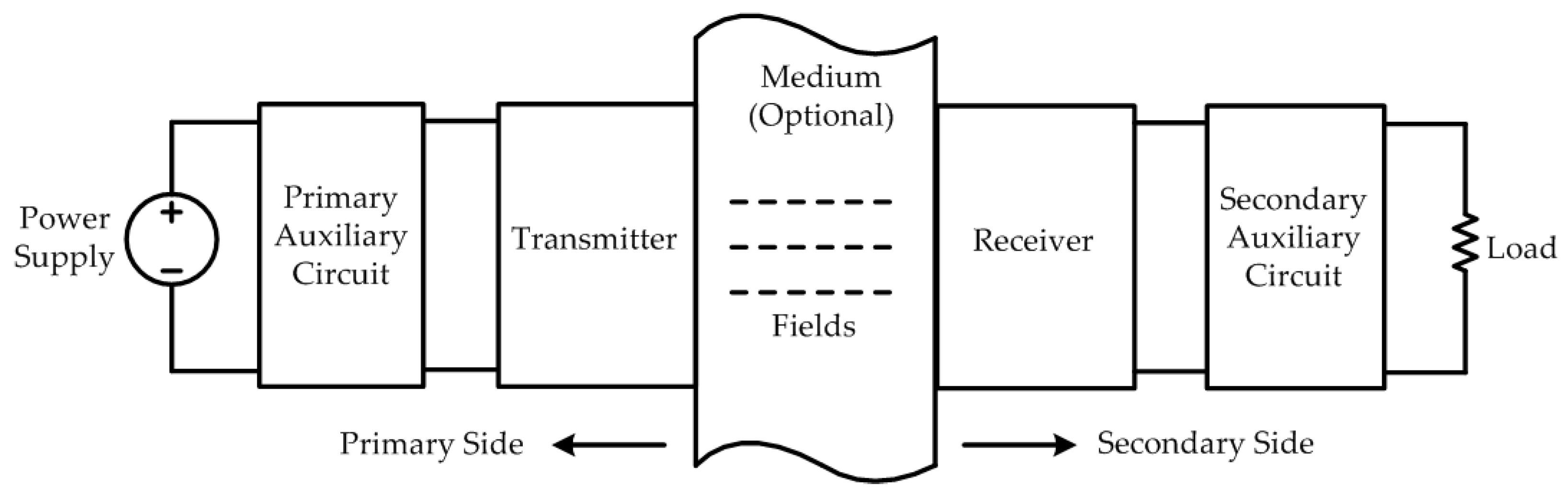
Figure 2.
Category of wireless power transfer systems.
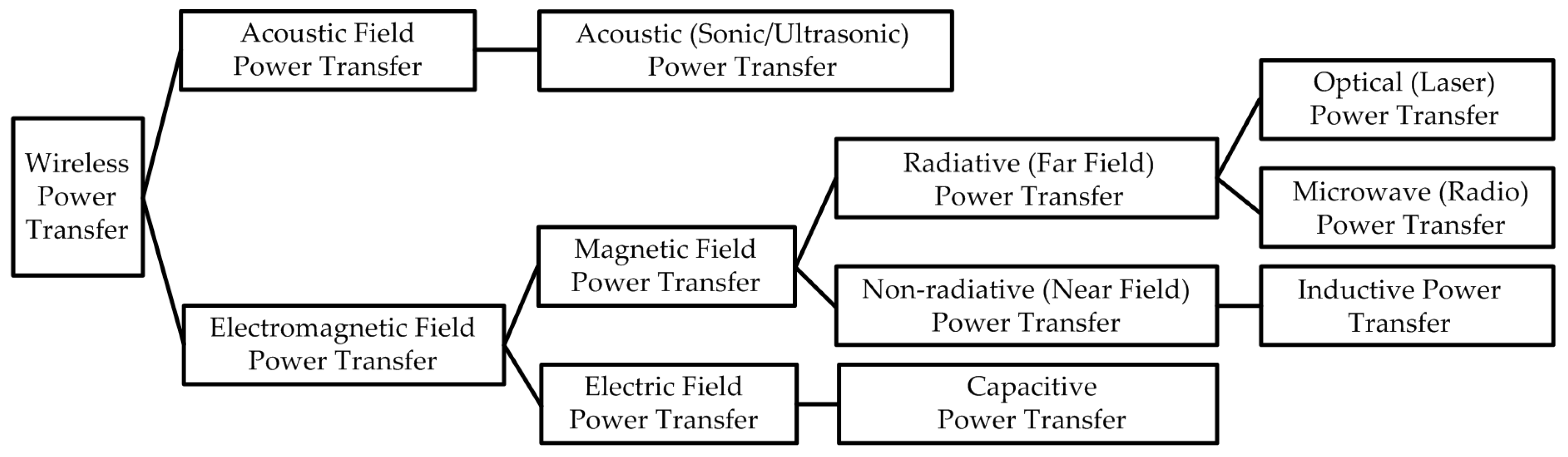
Figure 3.
Typical structure of a capacitive power transfer (CPT) system.
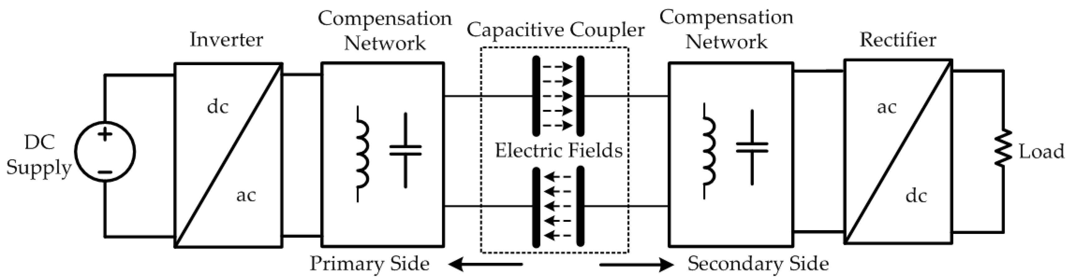
Figure 4.
Simplified circuit topology of a CPT system.

Figure 5.
The apparent power SM transferred to the secondary side.
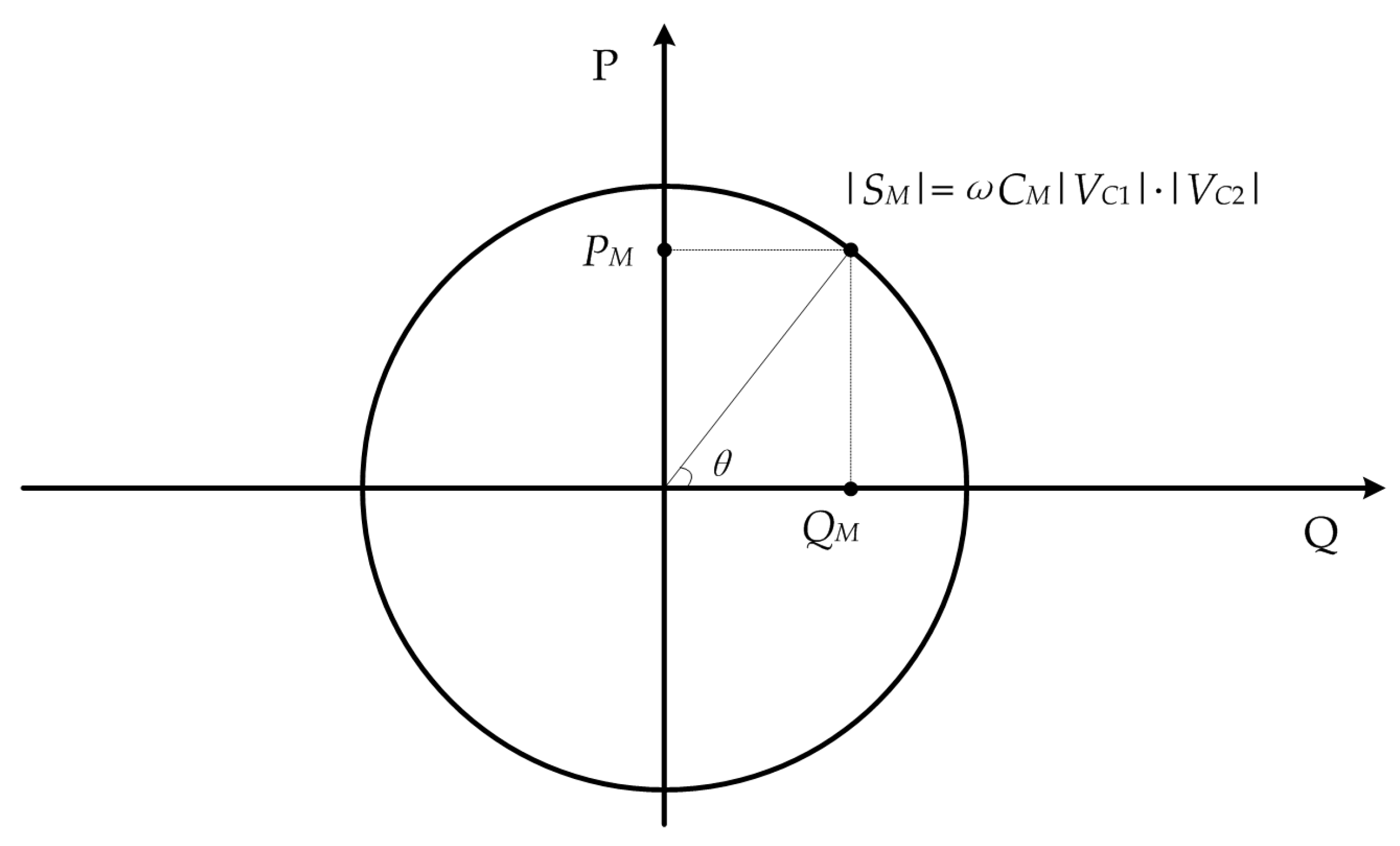
Figure 6.
The relationship between reactive power QM and active power PM.

Figure 7.
The maximum achievable system power PM at different fs and |VC1|, when CM = 10 pF and |VC1| = |VC2|.
Figure 7.
The maximum achievable system power PM at different fs and |VC1|, when CM = 10 pF and |VC1| = |VC2|.

Figure 8.
Plate voltage |VC1| at different CM and fs, when PM = 200 kW.

Figure 9.
Equivalent circuit topology of a CPT system with inductive networks.

Figure 10.
Equivalent circuit topology of a CPT system considering power losses of components.

Figure 11.
Efficiency of a CPT system at different values of kCQ and α.

Figure 12.
Maximum achievable efficiency of a CPT system at different values of kC and Q.

Figure 13.
Circuit topology of a CPT system based on sepic converter.

Figure 14.
Circuit topology of a CPT system based on class E converter.

Figure 15.
Circuit topology of a CPT system based on full-bridge inverter with double-sided L compensation.
Figure 15.
Circuit topology of a CPT system based on full-bridge inverter with double-sided L compensation.

Figure 16.
Circuit topology of a CPT system based on full-bridge inverter with double-sided LC compensation.
Figure 16.
Circuit topology of a CPT system based on full-bridge inverter with double-sided LC compensation.

Figure 17.
Circuit topology of a CPT system based on full-bridge inverter with double-sided LCL compensation.
Figure 17.
Circuit topology of a CPT system based on full-bridge inverter with double-sided LCL compensation.

Figure 18.
Circuit topology of a CPT system based on full-bridge inverter with double-sided LCLC compensation.
Figure 18.
Circuit topology of a CPT system based on full-bridge inverter with double-sided LCLC compensation.

Figure 19.
Circuit topology of a CPT system based on full-bridge inverter with double-sided CLLC compensation.
Figure 19.
Circuit topology of a CPT system based on full-bridge inverter with double-sided CLLC compensation.

Figure 20.
Circuit topology of a CPT system based on full-bridge inverter with m × n LC compensation.
Figure 20.
Circuit topology of a CPT system based on full-bridge inverter with m × n LC compensation.

Figure 21.
Structure of a two-plate capacitive coupler.

Figure 22.
Structure of a four-plate parallel capacitive coupler.

Figure 23.
Equivalent behavior source model of a capacitive coupler.
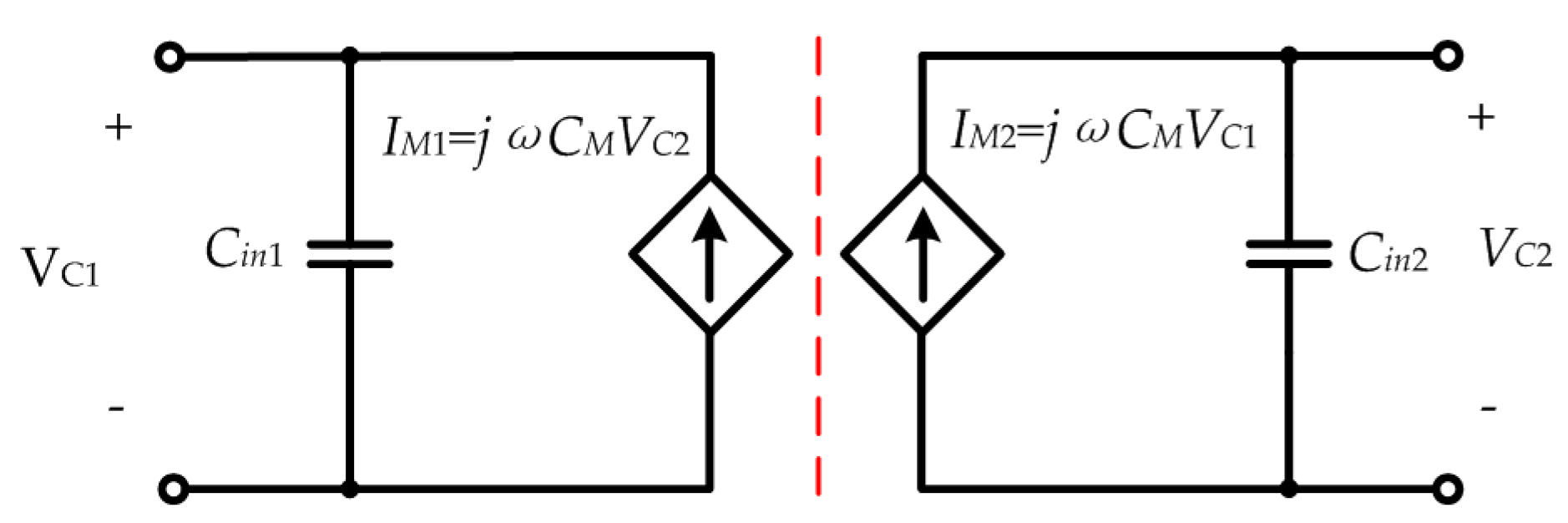
Figure 24.
Structure of a four-plate stacked capacitive coupler.
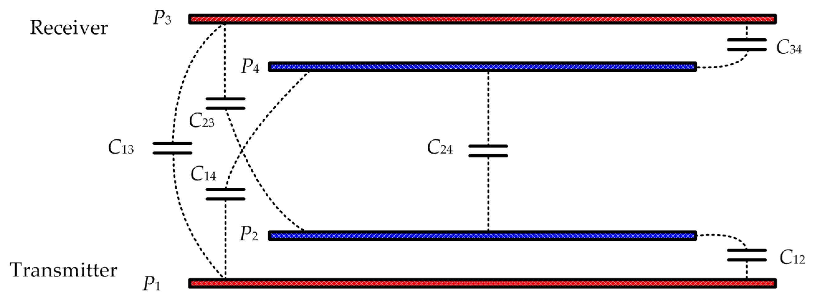
Figure 25.
Structure of a six-plate capacitive coupler.
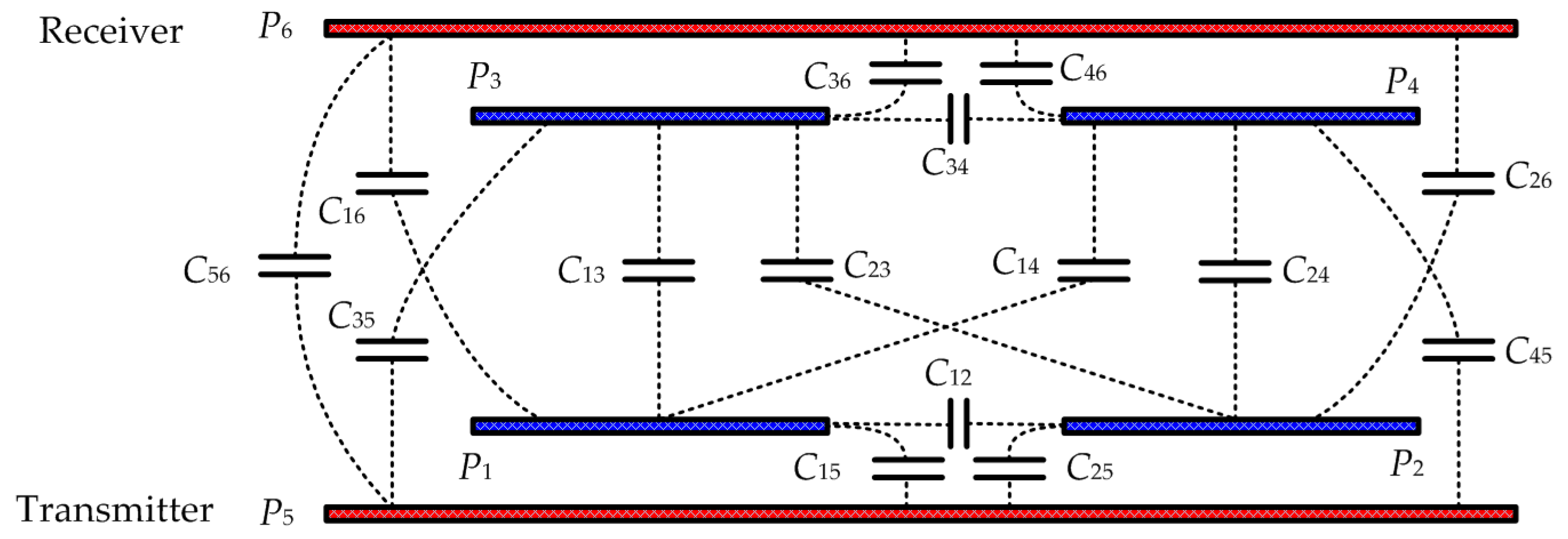
Figure 26.
An electric field repeater system based on two-plate coupler structure.

Figure 27.
An electric field repeater system based on four-plate parallel coupler structure.
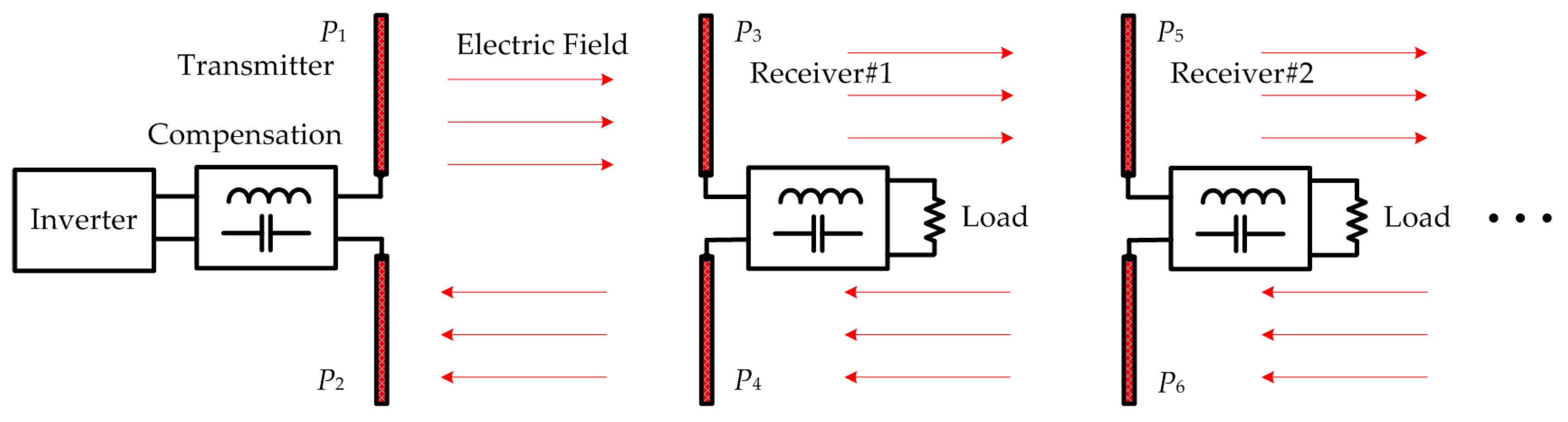
Figure 28.
Circuit topology of an IPT-CPT combined system.

Figure 29.
Electric field emissions of a 1.97 kW CPT system with six-plate capacitive coupler.

Figure 30.
Structure of a dynamic CPT system.
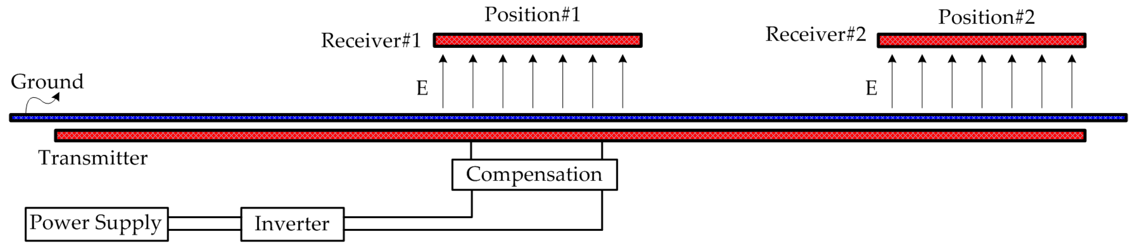

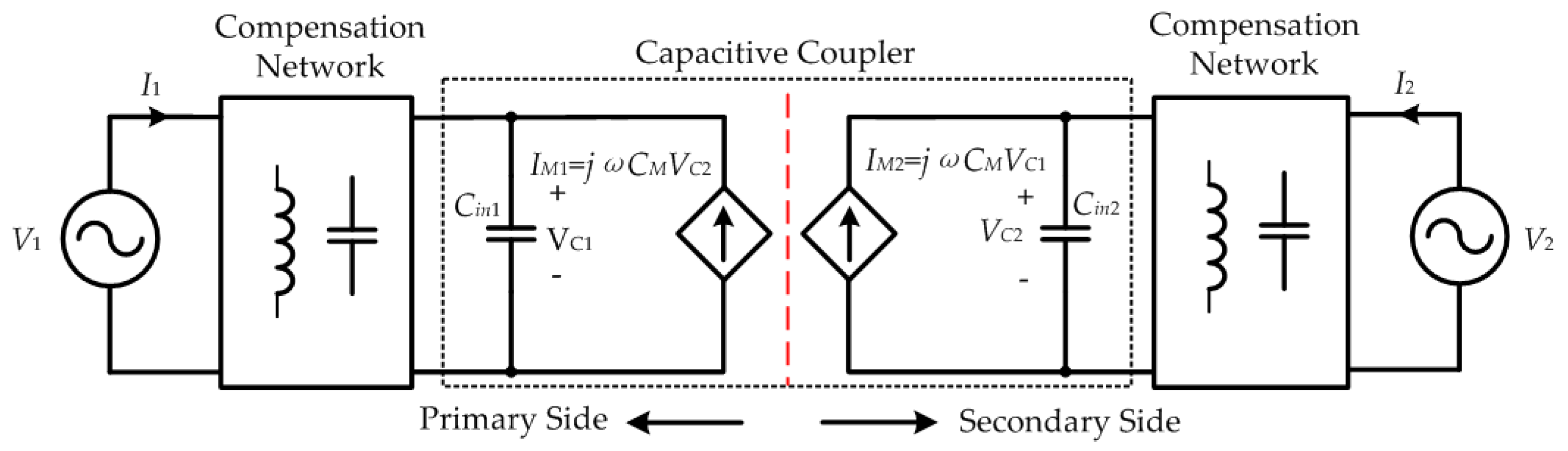
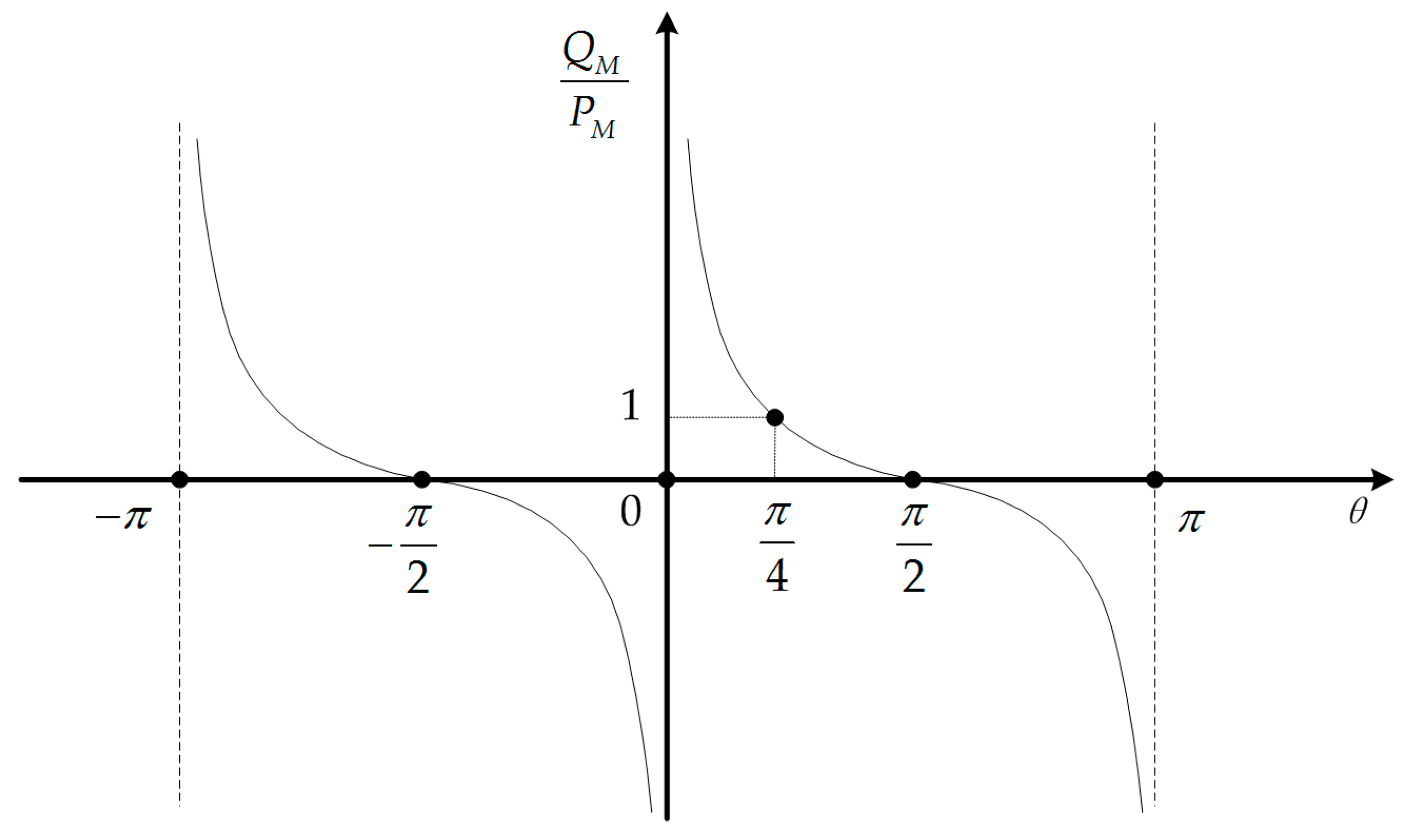
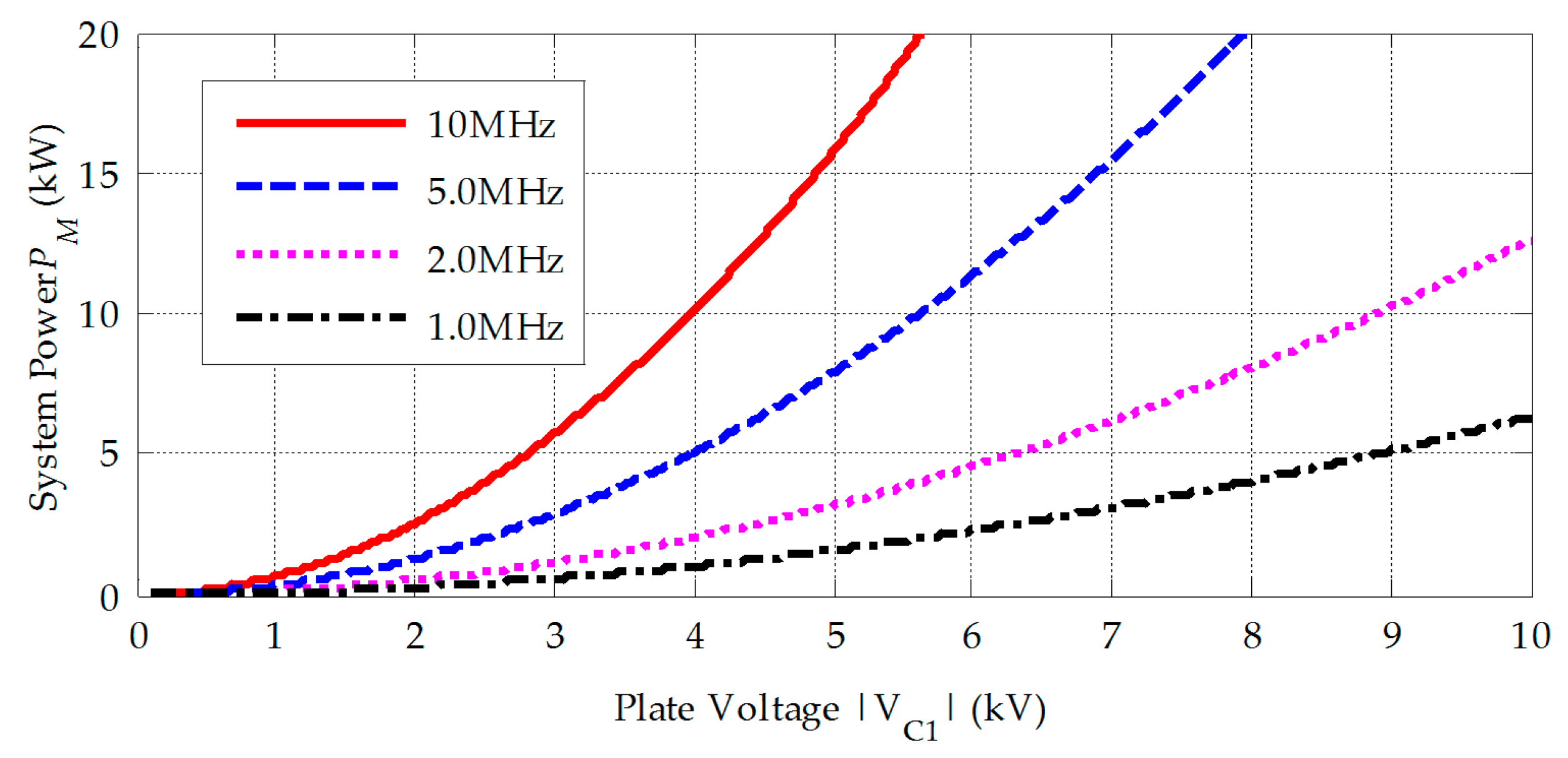
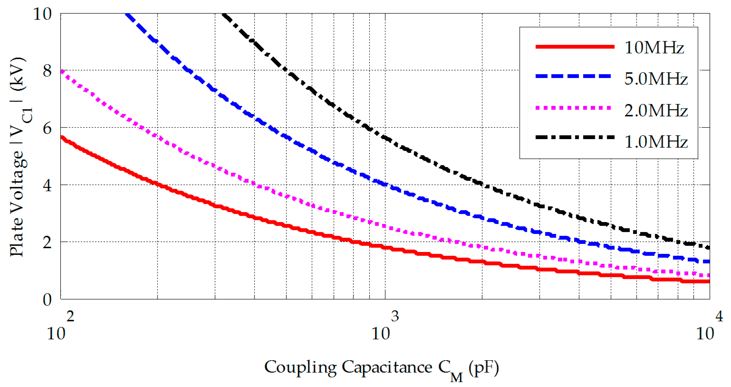
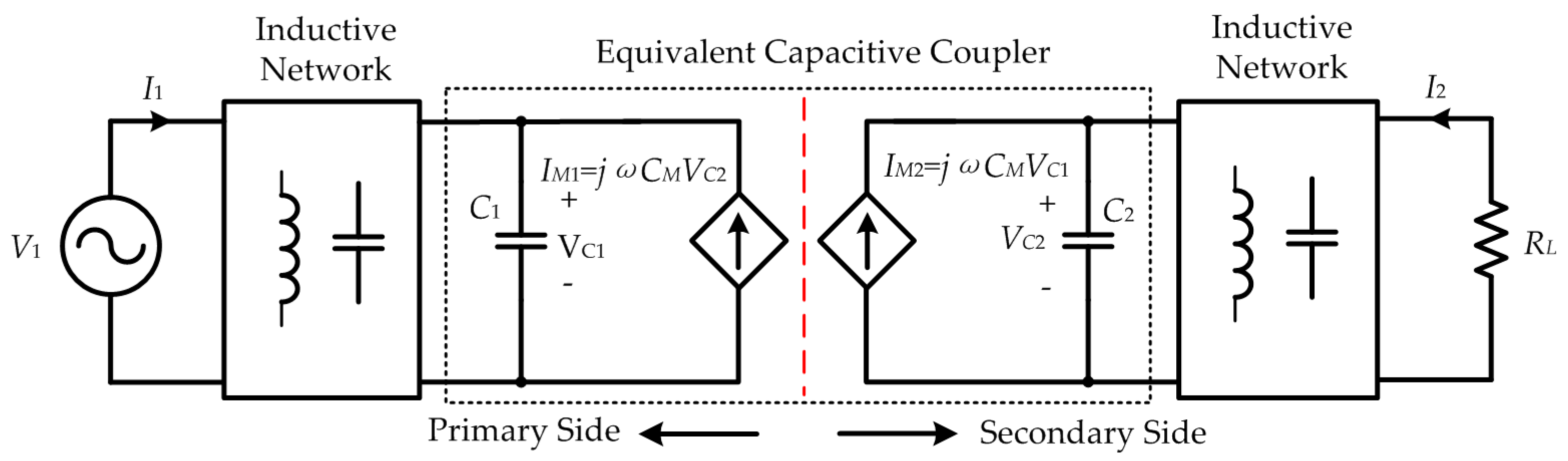
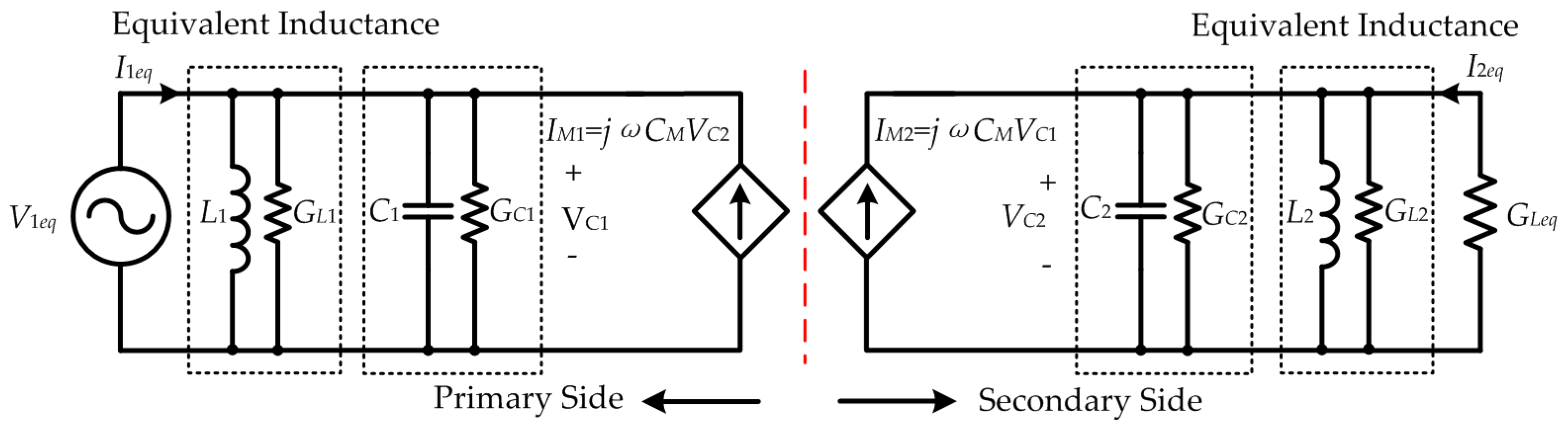
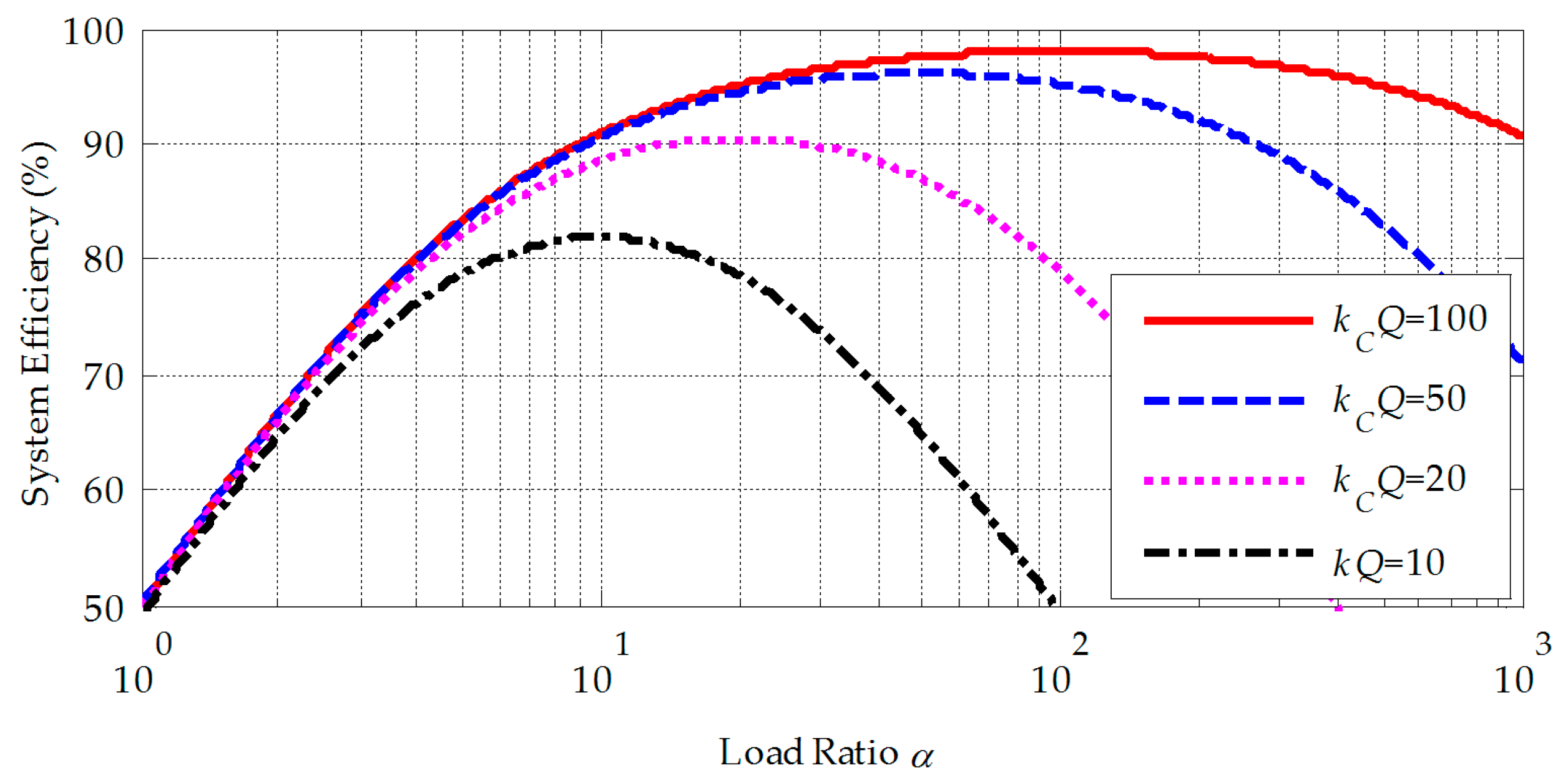
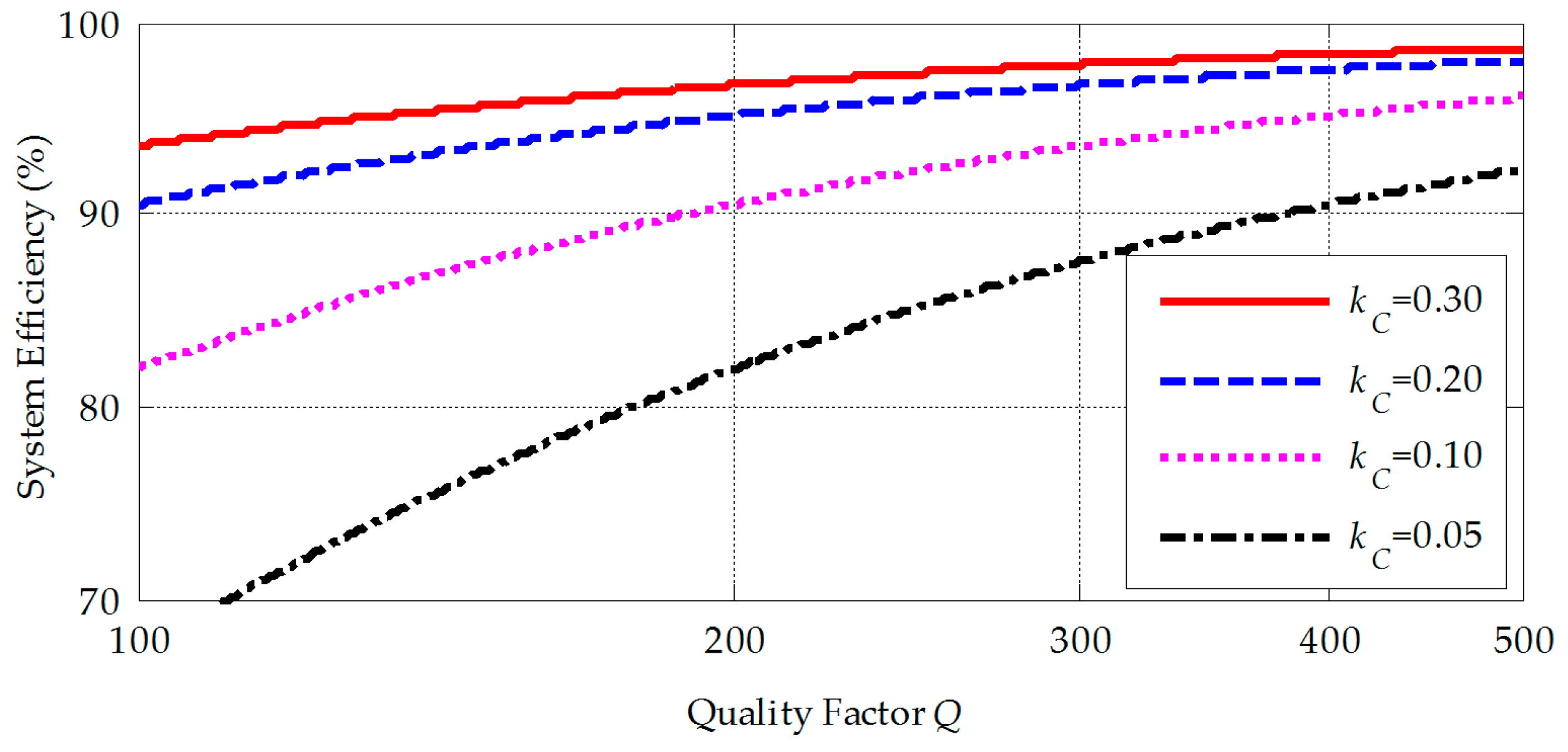
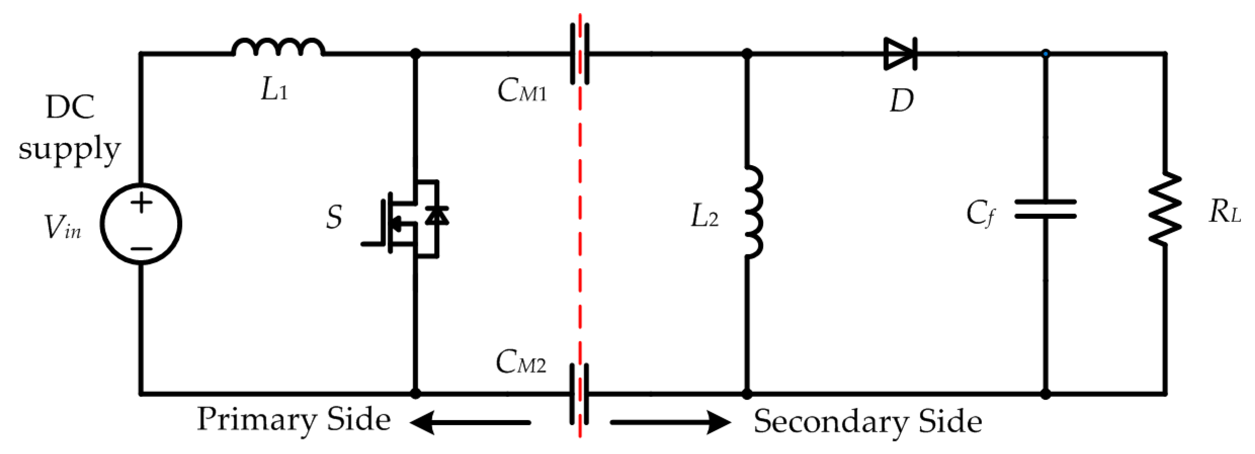
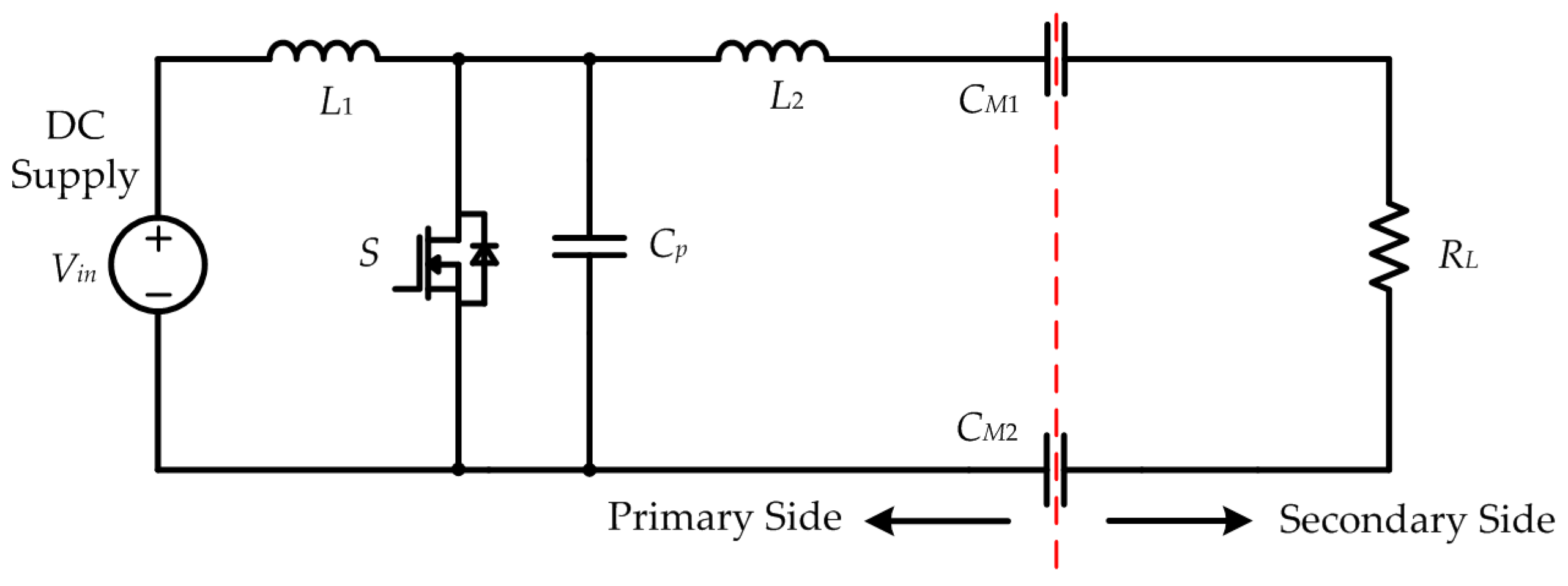
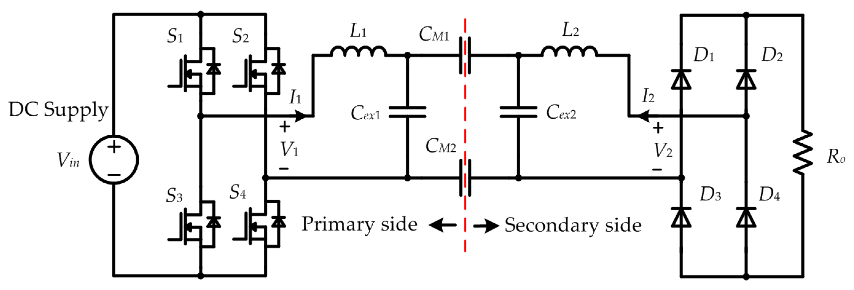
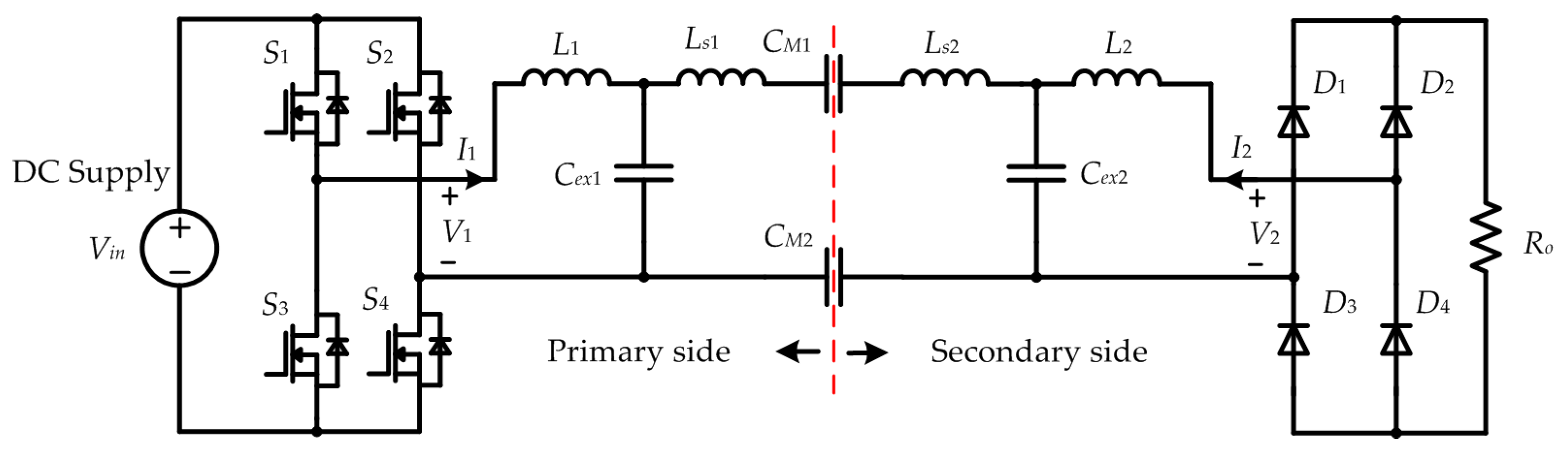
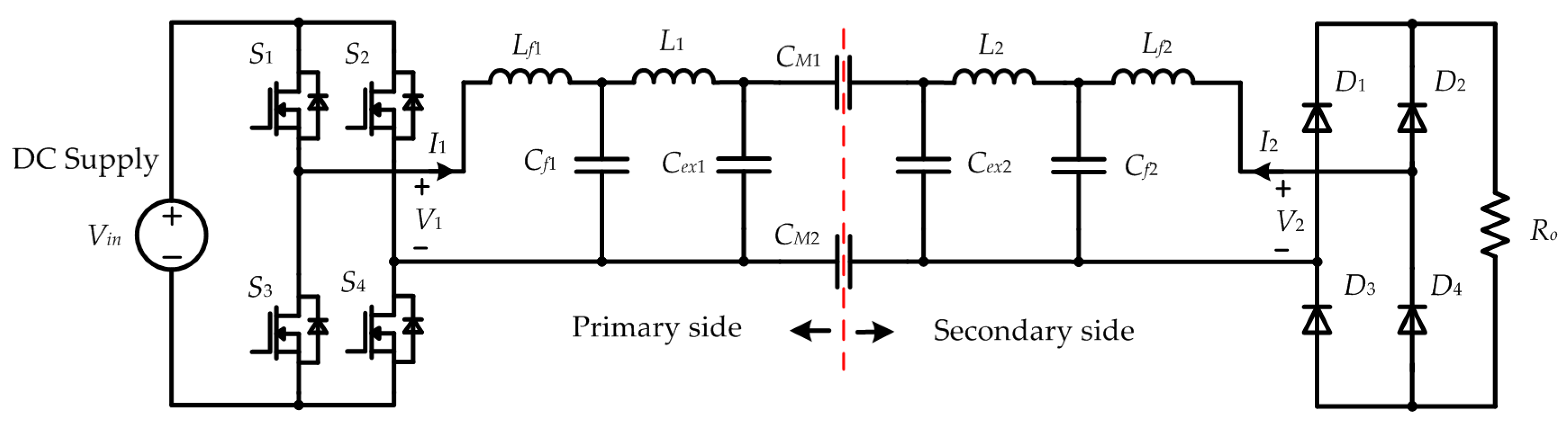
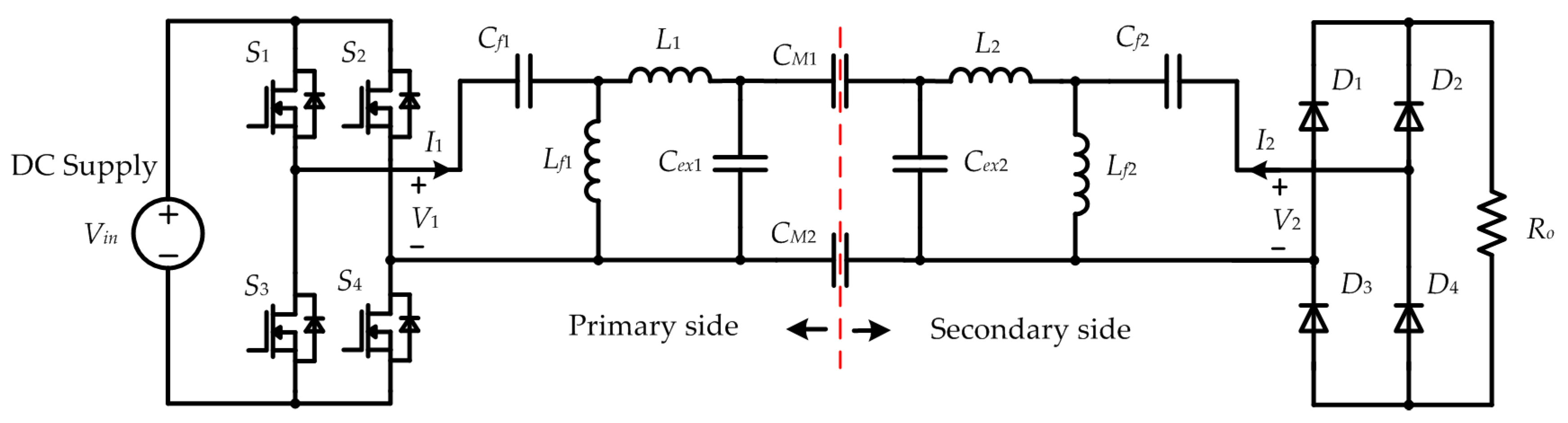
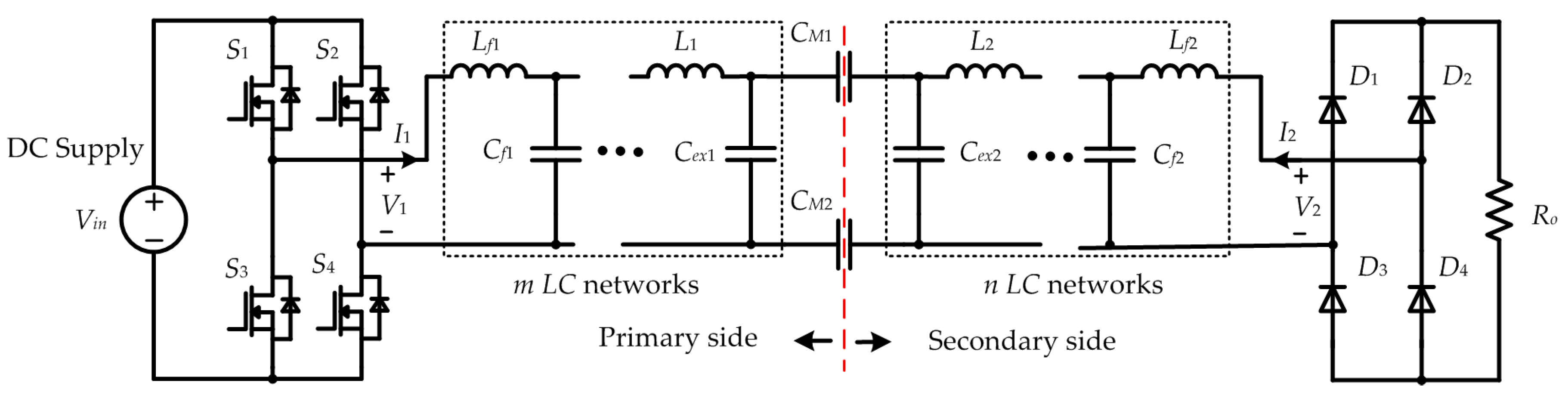
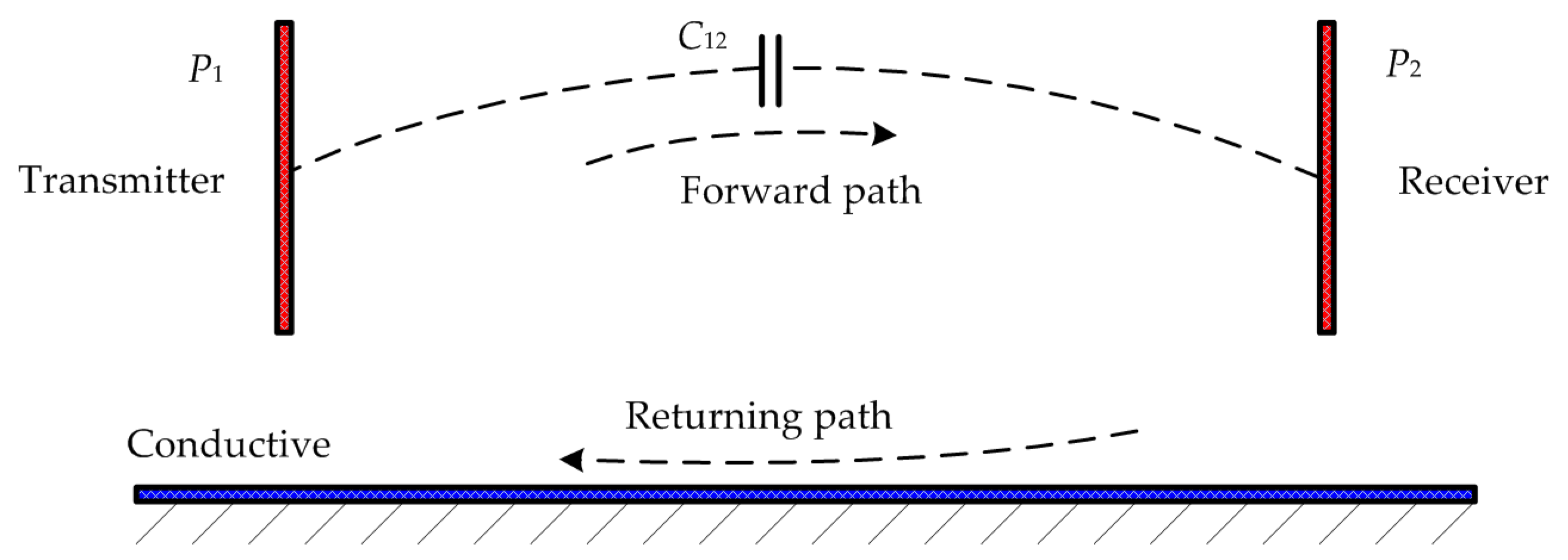
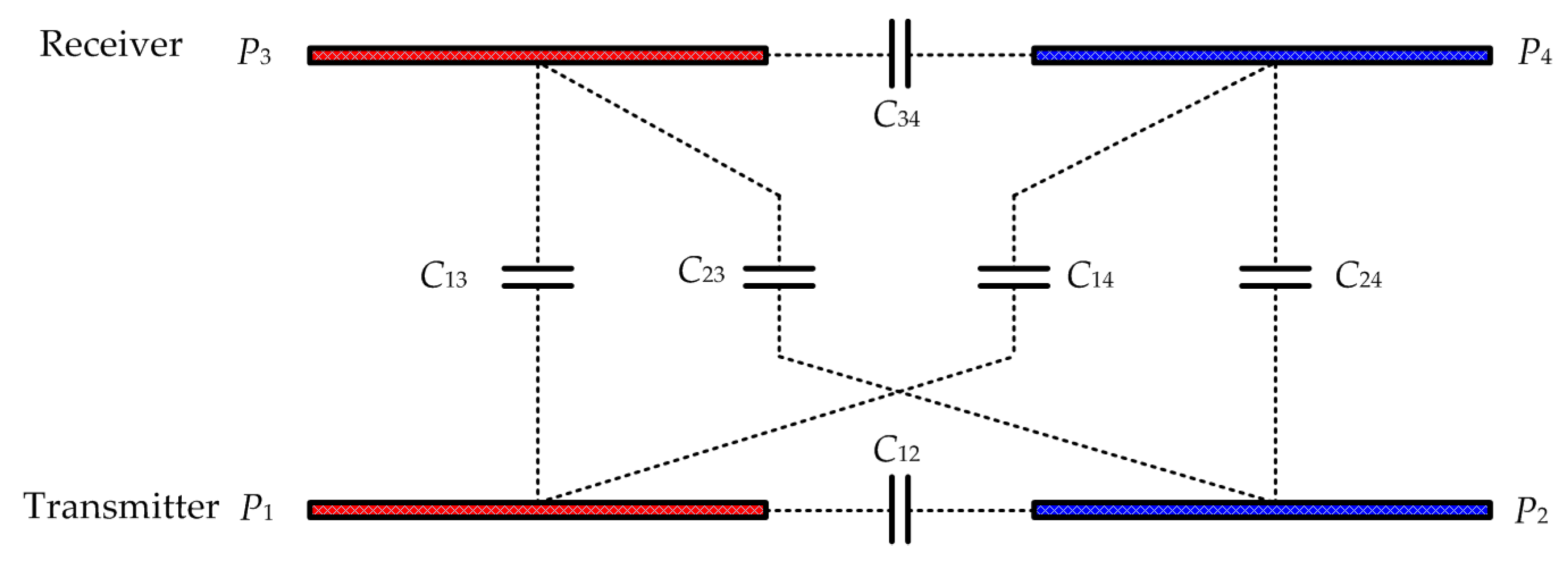
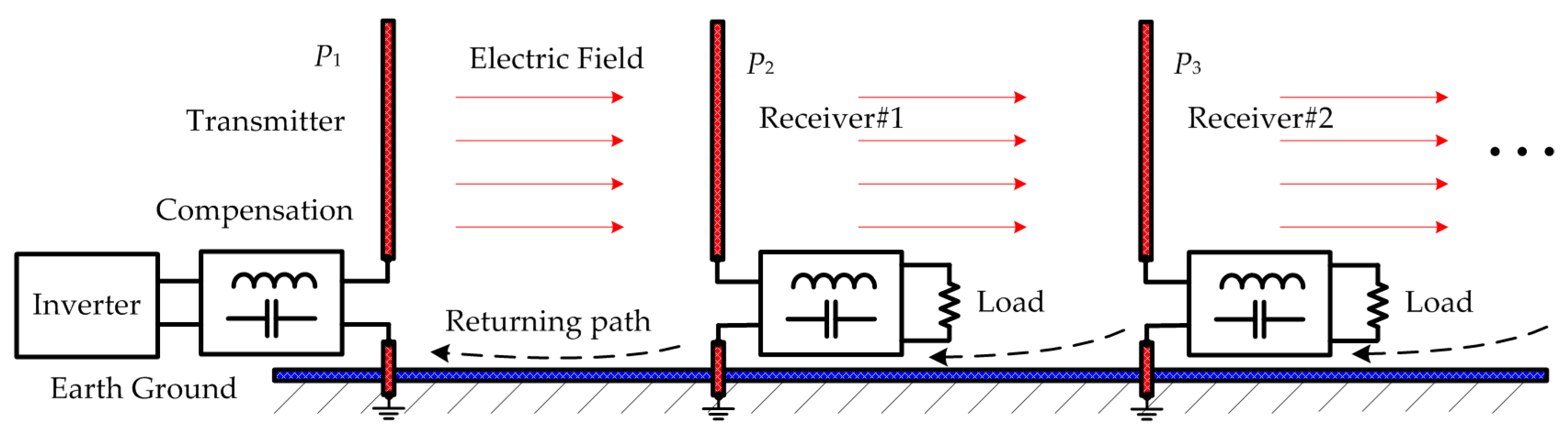
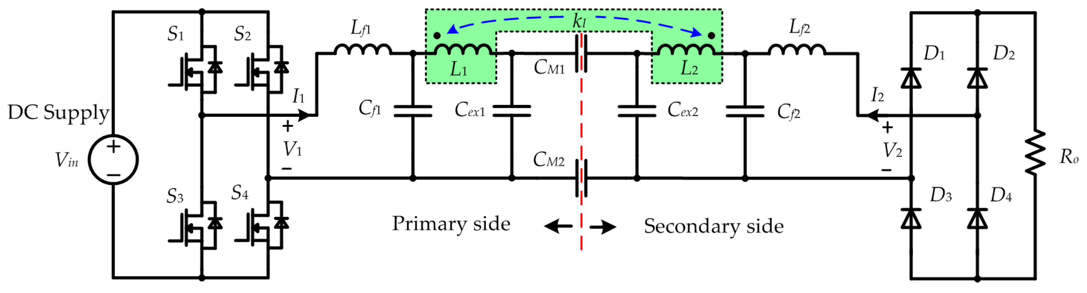
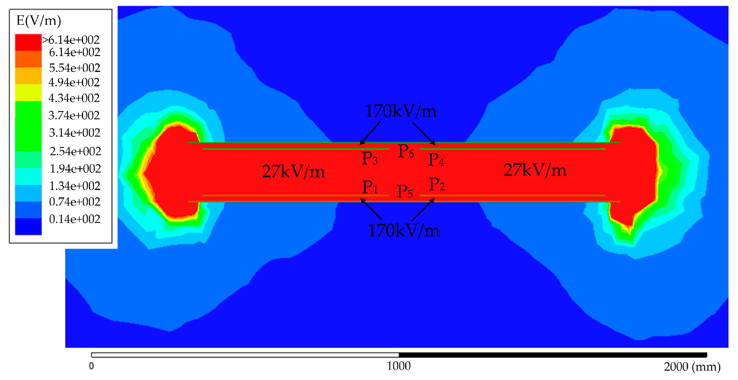
Table 1.
Comparison of different compensation circuits.
| Category | Inductance | Output Type | Output Expression | Output Power |
|---|---|---|---|---|
| Sepic CPT [42] * | Voltage source | |||
| Class E CPT [80] ** | Voltage source | |||
| Series L CPT [22] | Voltage source | |||
| LC CPT [35] | Current source | |||
| LCLC CPT [68] | Current source |
* In a sepic CPT system, D denotes the duty ratio of the PWM signal. ** In a class-E amplifier with 50% duty ratio, zero voltage and zero derivative at switch on instant, there is Vout = 0.76 Vin.
© 2017 by the authors. Licensee MDPI, Basel, Switzerland. This article is an open access article distributed under the terms and conditions of the Creative Commons Attribution (CC BY) license (http://creativecommons.org/licenses/by/4.0/).
Share and Cite
MDPI and ACS Style
Lu, F.; Zhang, H.; Mi, C. A Review on the Recent Development of Capacitive Wireless Power Transfer Technology. Energies 2017, 10, 1752. https://doi.org/10.3390/en10111752
AMA Style
Lu F, Zhang H, Mi C. A Review on the Recent Development of Capacitive Wireless Power Transfer Technology. Energies. 2017; 10(11):1752. https://doi.org/10.3390/en10111752
Chicago/Turabian StyleLu, Fei, Hua Zhang, and Chris Mi. 2017. "A Review on the Recent Development of Capacitive Wireless Power Transfer Technology" Energies 10, no. 11: 1752. https://doi.org/10.3390/en10111752
Note that from the first issue of 2016, this journal uses article numbers instead of page numbers. See further details here.