A Game Theory Approach to Multi-Agent Decentralized Energy Management of Autonomous Polygeneration Microgrids


Department of Natural Resources Management and Agricultural Engineering, School of Agricultural Production, Infrastructure and Environment, Agricultural University of Athens, 75 Iera Odos Street, Botanikos, 11855 Athens, Greece
*
Author to whom correspondence should be addressed.
Energies 2017, 10(11), 1756; https://doi.org/10.3390/en10111756
Submission received: 21 September 2017
/
Revised: 22 October 2017
/
Accepted: 26 October 2017
/
Published: 1 November 2017
Abstract
:Energy management systems are essential and indispensable for the secure and optimal operation of autonomous polygeneration microgrids which include distributed energy technologies and multiple electrical loads. In this paper, a multi-agent decentralized energy management system was designed. In particular, the devices of the microgrid under study were controlled as interactive agents. The energy management problem was formulated here through the application of game theory, in order to model the set of strategies between two players/agents, as a non-cooperative power control game or a cooperative one, according to the level of the energy produced by the renewable energy sources and the energy stored in the battery bank, for the purpose of accomplishing optimal energy management and control of the microgrid operation. The Nash equilibrium was used to compromise the possible diverging goals of the agents by maximizing their preferences. The proposed energy management system was then compared with a multi-agent decentralized energy management system where all the agents were assumed to be cooperative and employed agent coordination through Fuzzy Cognitive Maps. The results obtained from this comparison, demonstrate that the application of game theory based control, in autonomous polygeneration microgrids, can ensure operational and financial benefits over known energy management approaches incorporating distributed intelligence.
1. Introduction
The increase of human population, urbanization and modernization have led to one of most notable issues of the worldwide agenda, which is the outstanding growth of global energy demand. According to the International Energy Outlook 2016, the total energy consumption until 2040 will increase by 48%, which reflects an increase in the consumption of fossil fuels. However, although energy demand is expected to grow, hundred millions of people will still be left without basic energy services. Taking into consideration that nowadays more than 1 billion of people do not have access to electricity as well as the continuous increase of the use of fossil fuels that has a significant environmental impact, renewable energy generation is an alternative, sustainable and economically viable solution [1].
Most of these people live in island and coastal regions and apart from electricity they face a variety of problems regarding access to potable water and fuel for transportation. A sustainable solution to potable water shortage is water desalination powered by renewable energy [2]. Reverse osmosis desalination has the widest global acceptance and has been implemented not only for sea or brackish water desalination, but also for waste water treatment [3]. During the past two decades, several desalination units powered by renewable energy sources (RES) have been implemented [4]. Furthermore, coupling RES with hydrogen systems has been presented as promising and can increase clean technologies’ penetration in the transportation sector [5]. A hydrogen subsystem usually is composed of a water electrolyzer, which produces the hydrogen, a hydrogen storage tank which acts as energy storage, a refuelling system which supports the dispensing hydrogen into fuel cell vehicles and a fuel cell which produces electricity from the stored hydrogen. Autonomous polygeneration microgrids (APMs) which enable renewable distributed generation have been investigated technically and has been proven as an economically profitable solution, in order to cover all the needs (electricity, potable water and fuel for transportation) present in the area that they serve [6].
Microgrids are low or medium voltage power grids which can integrate renewable energy sources (RES), conventional generators, energy storage systems and energy consumption units [7]. Microgrids can operate at either grid-connected or islanded (autonomous) mode [8]. In the grid-connected mode, the microgrid purchases power from the grid or inject power into it, in order to regulate power balance between power supply and load demand and maximize its operational benefits [9]. In the islanded mode, the microgrid operates autonomously and supply power to the customers by keeping the electrical interchange between production and consumption stable [10]. Energy management systems (EMS) are required for the effective operation of microgrids [11], and it is eventually crucial to incorporate optimal control strategies for their successful management. EMSs for microgrids have roughly been distinguished to two main classes; centralized EMS (CEMS) and decentralized EMS (DEMS) [12].
CEMSs are hierarchical systems whose central controller collects the required information data from a microgrid’s components, provide control commands on them directly performing a centralized operation and acts as an overall system manager. Various CEMS architectures for microgrids have been investigated and applied in order to efficiently control the different energy sources, minimize operating costs and emissions and achieve efficient power management [13]. The advantages of CEMS include the easy overall observation of whole system’s operation and the minimization of conflicts as the central controller takes all the ultimate decisions. In spite of the CEMS’s benefits, this approach presents some drawbacks, such as high powerful computing and communication ability to handle the huge amount of data. Also, CEMS presents low flexibility as it must be updated if there is any change to the configuration of the microgrid.
On the other hand, DEMS architecture is more flexible and less complex as it is based on a network of autonomous local controllers. In DEMS architecture, each controller demonstrates a certain level of intelligence and makes decisions for each component in order to achieve their goals. Therefore, the components of the system are independent to perform their task, forming an intelligent and dynamic system which can operate effectively and meet the variable conditions, such as the intermittency of RES and the load variations. DEMS can employ advanced control techniques because of microcontrollers’ technology evolution. DEMS have been implemented in microgrids [14] and demonstrate lower investment cost than CEMS because a central server with high computing power is more expensive than the cost of the microcontrollers along with the open software and hardware platforms [15].
The autonomous microgrid topology can be applied in order to meet the demands of settlements and villages all around the world. The EMSs that have already being developed for a variety of such APM topologies are mainly centralized. However, the larger the system becomes, both in terms of rated power and in terms of the number of producers and consumers, the more complex its management and control becomes. A decentralized architecture, as it was described above, can be beneficial for the APM topology, which is usually implemented in remote areas. Moreover, a number of research studies have been established on EMS for microgrids and distributed generation using either hierarchical EMS [16] or computational intelligence techniques such as fuzzy logic [17], fuzzy cognitive maps [18], genetic algorithms [19] and neural networks [20].
Over the past few years, extensive research has been conducted on multi-agent systems (MAS) in the field of electrical power systems [21,22], providing high intelligence and evolving the decentralized technology in the field of management and control of microgrids. MAS based EMS architectures have been widely used for distributed control and demand side energy management in microgrids [23]. Moreover, a MAS based on hierarchical DEMS was presented in [24], in order to ensure energy supply in distributed generation systems, while a MAS-DEMS that employs fuzzy cognitive maps were presented in [15] for the energy management and control of an APM. All these studies demonstrate the beneficial application of MAS in microgrids where the players/agents were cooperating and various decision making methods and control strategies were used to attain the optimal microgrid performance.
The coordinated operation of a distributed energy system can be achieved by using a multi-agent strategy through the assistance of computational intelligence techniques. In all cases mentioned above, the application of the multi-agent theory assists to solve the energy management problem in distributed energy management systems by exploiting a theoretical framework relying on the cooperation among the agents. Nevertheless, in several cases, the communication between the agents could lead to high costs of communication networks, as a large amount of communication data is needed to achieve optimal balance between them for the efficient operation of the energy systems. Moreover, an interactive operation among multiple agents in an energy system appears very often. In these cases, the goals of each agent are influenced by the actions of the remaining agents, while it is often possible that cooperation of the agents cannot be established, because they have competitive goals or different strategies which influence agents’ actions. Traditional computational methods such as genetic algorithms, neural networks, etc. are normally suitable for energy coordination problems, but they cannot be applied in non-cooperative energy problems where the agents interact with each other, since the majority of their parameters depend on experience and they present slow dynamic responses. The non-cooperative game model is widely adopted in the case where competitive agents or agents with interactive operations are essentially involved. Game theory provides us with a conceptual as well as an analytical framework with a set of mathematical tools enabling the study of complex interactions among players/agents, even in the non-cooperative case. Game theory has been proposed and used as a powerful tool to represent the agents’ interactions and achieve the optimum strategies in non-cooperative games [25]. The Nash equilibrium concept is the most favourable solution concept for non-cooperative games, where there is no leader-follower relationship among the players and the players can achieve their optimal objectives [26]. Game theory has been applied in electrical power markets for electricity trading [27], in distributed generation systems to minimize cost of resources [28], in load balancing [29] and in demand side energy management systems for microgrids [30,31,32]. Moreover, game theory is expected to constitute a powerful tool for the design, analysis, energy management and control of the future smart grids [33].
The benefits of a MAS-DEMS for the control and management of complex systems with many devices like a polygeneration microgrid (incorporating a desalination unit and a hydrogen electrolyzer) were presented in one of our previous works [15]. The present paper exhibits the development and investigation through simulation of a MAS and game theory based control strategy for the DEMS of an APM. Each device of the APM was modelled and controlled by a particular agent. The managed devices operated in variable load as they present higher efficiencies and their operation point was decided by the involved negotiating agents. Furthermore, the MAS makes the decisions concerning the production of potable water and hydrogen and the utilization of the hydrogen as fuel. The energy management system was formulated into two control power games, namely a non-cooperative game and a cooperative one between players/agents, according to the power production of the renewable energy sources and the stored energy in the battery bank. When there is a surplus of energy, i.e., the power production and the stored energy can cover the load demand, the desalination unit and the electrolyzer are activated by their agents. The two agents/players compete each other and they must make decisions among themselves about their strategies, in order to maximize their profits. A non-cooperative game was built between the two competitive interacting players/agents. The main objective of each agent is to produce as much as possible potable water and hydrogen, respectively. Therefore, the solution of the game will give the optimum operation points of the desalination unit and the electrolyzer. In a different case, the energy generated by the RES and the stored energy of the batteries cannot meet the load demand and the fuel cell unit must be activated as it is used as a backup power source. A cooperative game was then built, where the agents/players which represent the battery bank and the fuel cell, cooperate with each other with the main preference to meet the load demand. Therefore, the optimum operation point of the fuel cell unit, consuming as little hydrogen as possible, was determined. Therefore, the MAS-DEMS used game theory approach in each time step in order to settle the load distribution. In game theory, there are several types of equilibrium such as Nash equilibrium, Stackelberg equilibrium, and Bayesian equilibrium. In this paper, The Nash equilibrium was used to compromise the different preferences of the agents/devices, maximizing their profits as all the agents are equally treated.
The MAS-DEMS proposed in this paper was afterwards compared technically and economically with the MAS-DEMS of [15], in which the benefits of the MAS-DEMS were presented in comparison with the CEMS approach. In that paper [19], the intelligent agents were cooperating with each other and were employing Fuzzy Cognitive Maps (FCM) theory for the demand side energy management. The two systems compared both financially and operationally. The comparison between the two systems carried out for a same APM topology (same electrical demand, water and fuel need) and the results of the comparison have shown that the energy management system proposed in the present paper offers lower power losses and lower cost for a 20 year investment period, proving the financial and operational benefits of the game theoretic approach to the MAS-DEMS design in autonomous polygeneration microgrids.
The rest of this paper is organized as follows: in Section 2, the AC microgrid considered in this study is described, together with the materials and methods used for the development of the MAS-DEMS. Section 3 describes the design of the MAS-DEMS that was used for the energy management and control of the APM. The optimization parameters are discussed in Section 4. In Section 5, the results of the simulation of MAS and game theory based control strategy for the DEMS of the APM are discussed and its comparison with a MAS-DEMS based on FCMs is also presented. The paper is completed in Section 6, wherein the key benefits of the proposed approach are discussed and summarized together with future research directions.
2. Materials and Methods
2.1. Microgrid Configuration
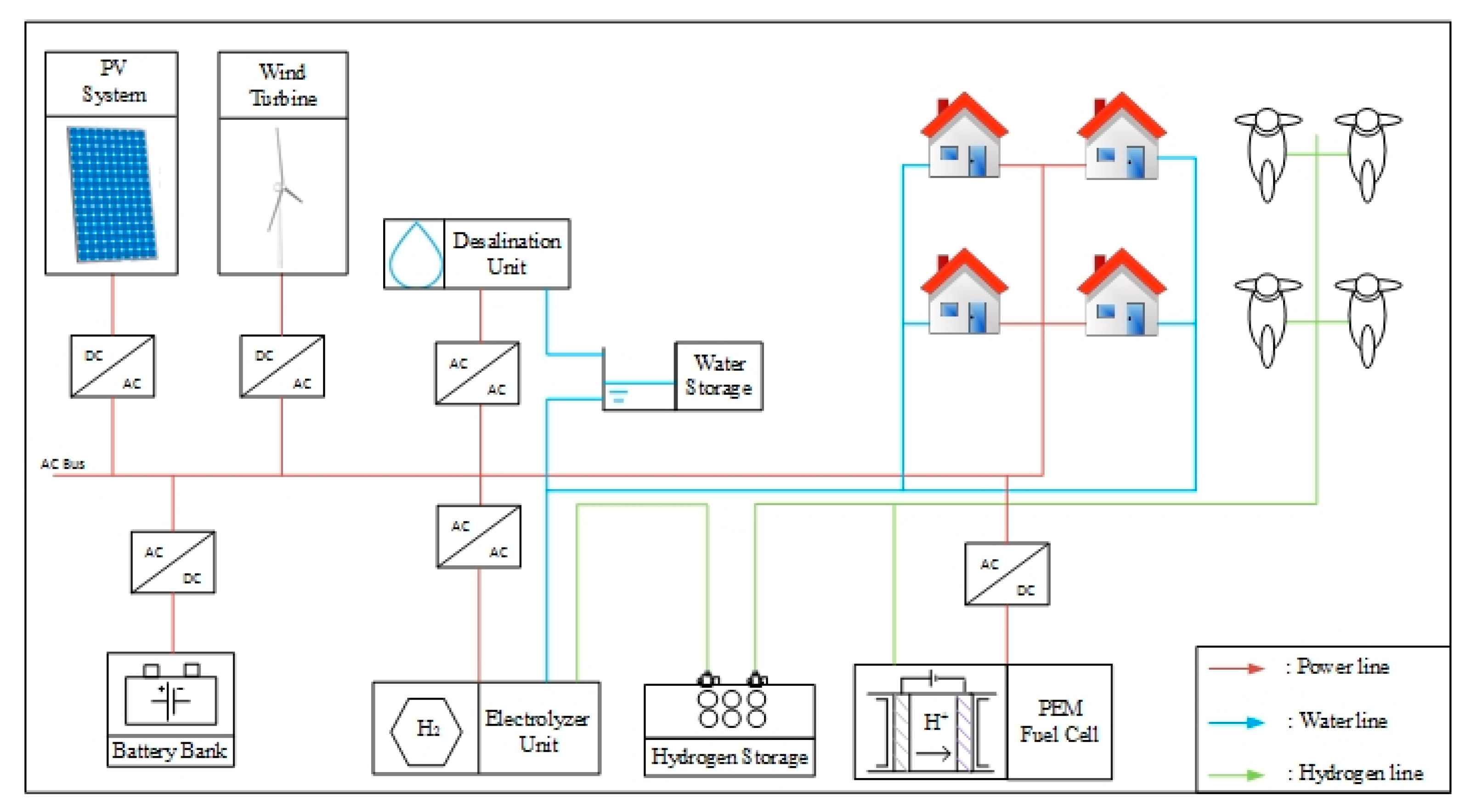
A schematic representation of the microgrid configuration is depicted in Figure 1. The microgrid constitutes of the following components:
- Distributed energy sources: A typical monocrystalline silicon photovoltaic array installed on a vertical tracker, a horizontal axis wind turbine and a typical Proton Exchange Membrane (PEM) fuel cell were considered.
- Storage devices: A deep discharge solar lead acid 48 VDC battery bank, a water tank and a metal hydride tank were considered.
- Energy consumptions units: Household electrical consumptions (e.g., lighting, refrigeration, cooking appliances etc.), a reverse osmosis desalination unit and hybrid fuel cell-battery scooters were considered.
2.2. Intelligent Agents
An intelligent agent (IA) is an autonomous entity that is placed in an environment and is capable to monitor and acts upon it in order to achieve its design objectives [34]. The intelligent agent processes the received information, makes comparisons with defined rules, investigates possible decisions and finally selects the optimum solution while it cooperate, coordinate or negotiate with other agents in a specific environment. According to the literature [35], an intelligent agent has four key features, namely, autonomy, social ability, reactiveness and pro-activeness.
A basic element to determine an IA, is its logic which can be mathematically defined as a function [34]. The function of the agent is defined as S → A and the perception as S → P where S = {s1, s2, …, sn} is the information from the environment, A = {a1, a2, …, an} are the abilities of the agent, P are the data of perception and I = {i1, i2, …, in} is the internal situation.
Russel and Norving [34] outlined five basic classes of intelligent agents that embody the principles underlying almost all intelligent systems and are based on their extent of perception, intelligence and capability. The classes are (a) the Simple reflex agents which receive incentives and react directly to the environment according to the predetermined rules; (b) the Model— based reflex agents which interpret the information they receive to determine their action; (c) the Goal—based agents which are an extension of the model-based agents and they are able to set goals on taking decisions; (d) the Utility—based agents which can conduct with other agents, coordinate the flow of the information and can address situations when the goals are in conflict and (e) the Learning agents which can operate in unknown environments and become more competent.
2.3. Game Theory Analysis
Game Theory is a mathematical framework that models and analyzes situations where multiple decision makers interact [36]. Using strategic decisions, each participant try to achieve its objectives [37].
A game is a tuple , where:
- N is the set of players
- Ai is the set of actions of player i where
- is the utility function of player i which can be a profit (maximize) or a cost (minimize)
There are several types of games and corresponding representations. The two main distinctions of game theory are between non-cooperative and cooperative game theory. In cooperative games, the players request optimal concerted actions or reasonable cost/reward sharing rules that make the coalitions stable and the players are allowed to communicate and to receive side payments in order to act as one entity by improving their position in the game. Non-cooperative game theory can be used to analyse decision making processes strategies of independent players which have conflict preferences [33]. In these games, taking into consideration the actions of the other involved players, each player optimizes its utility function automatically without coordination between the strategic choices of each player. Nash equilibrium is one the most important solution concepts for game theory [38]. In Nash equilibrium, no player can increase its revenues by changing unilaterally its strategy, given that the actions of the other players are fixed. Therefore, a mutual optimal response from all the players is achieved. Nash equilibrium in non-cooperative games is the optimum solution when there is no leader-follower relationship and each player competes against the others in order to maximize its utility function. In cooperative games, the strategies are achieved when the strategy set can maximize the revenue of each player.
2.4. Optimization Method
Optimization process aims to find the optimal solution of an objective function for given set restrictions and constraints. Several optimization techniques have been proposed for engineering problems, most of which use as information the derivative of the objective function, as the Langrage multipliers method [39]. However, when the problem is complicated with probabilistic rules and at the same time the transition doesn’t follow deterministic rules, evolutionary algorithms can be used to solve it. Typical evolutionary algorithms include Genetic Algorithms, Simulated Annealing, Particle Swarm Optimization (PSO), Ant Colony Optimization and a number of variations [40]. These algorithms can explore the area where the solution is located, so the solution presents a global optimum instead of a local one [41]. In this paper, the optimization method used is PSO. The PSO method is a stochastic optimization, evolutionary and simulating algorithm and its purpose is to find the optimum solution of an objective function by performing a stochastic search based on a population. PSO opted because of the benefits it presents; it can optimize continuous and discrete variables simultaneously, it requires less memory space and central processing unit (CPU) speed [42], and it presents good results in energy systems optimizations [43,44]. The PSO settings that were used are presented in Table 1 [15,18].
2.5. Modeling, Simulation and Optimization Platform
The microgrid was developed, simulated and tested using the TRNSYS 17 [45] software package which is a commercial transient simulation program for solar energy systems and facilitates the addition to the program of mathematical models not included in its library. The simulation of the photovoltaic modules, wind turbine and battery bank was undertaken using TRNSYS components [46]. Custom routines have been used for the simulation of desalination unit [47], fuel cell unit [48] and electrolyzer unit [49]. Matlab software package was used to design, model and simulate the agents in the microgrid environment. GenOpt 3 [50] software package provided the optimization libraries and TRNOPT 2 [51] acted as an interface between TRNSYS and GenOpt.
3. MAS-DEMS of the Microgrid
3.1. Overview
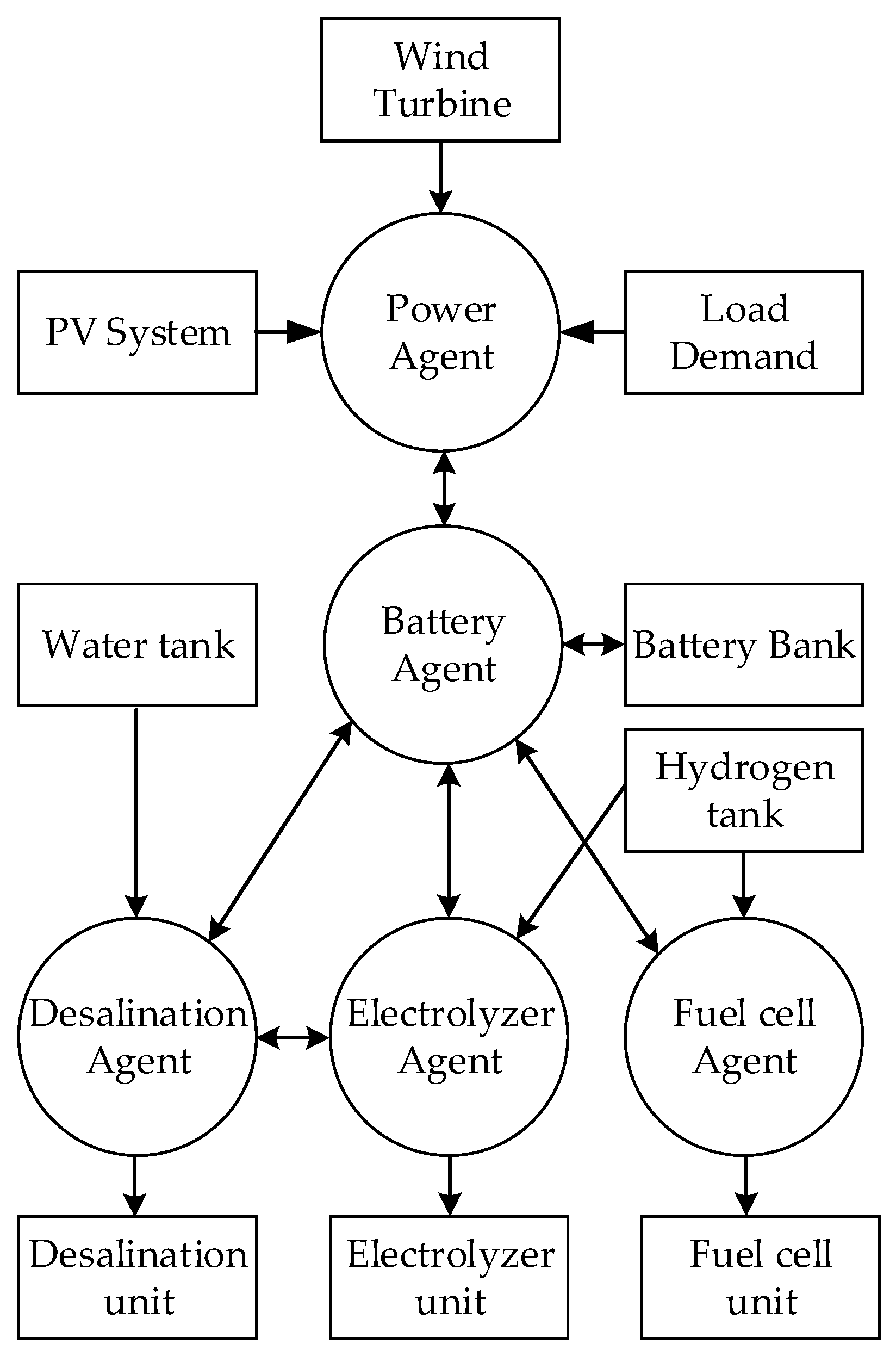
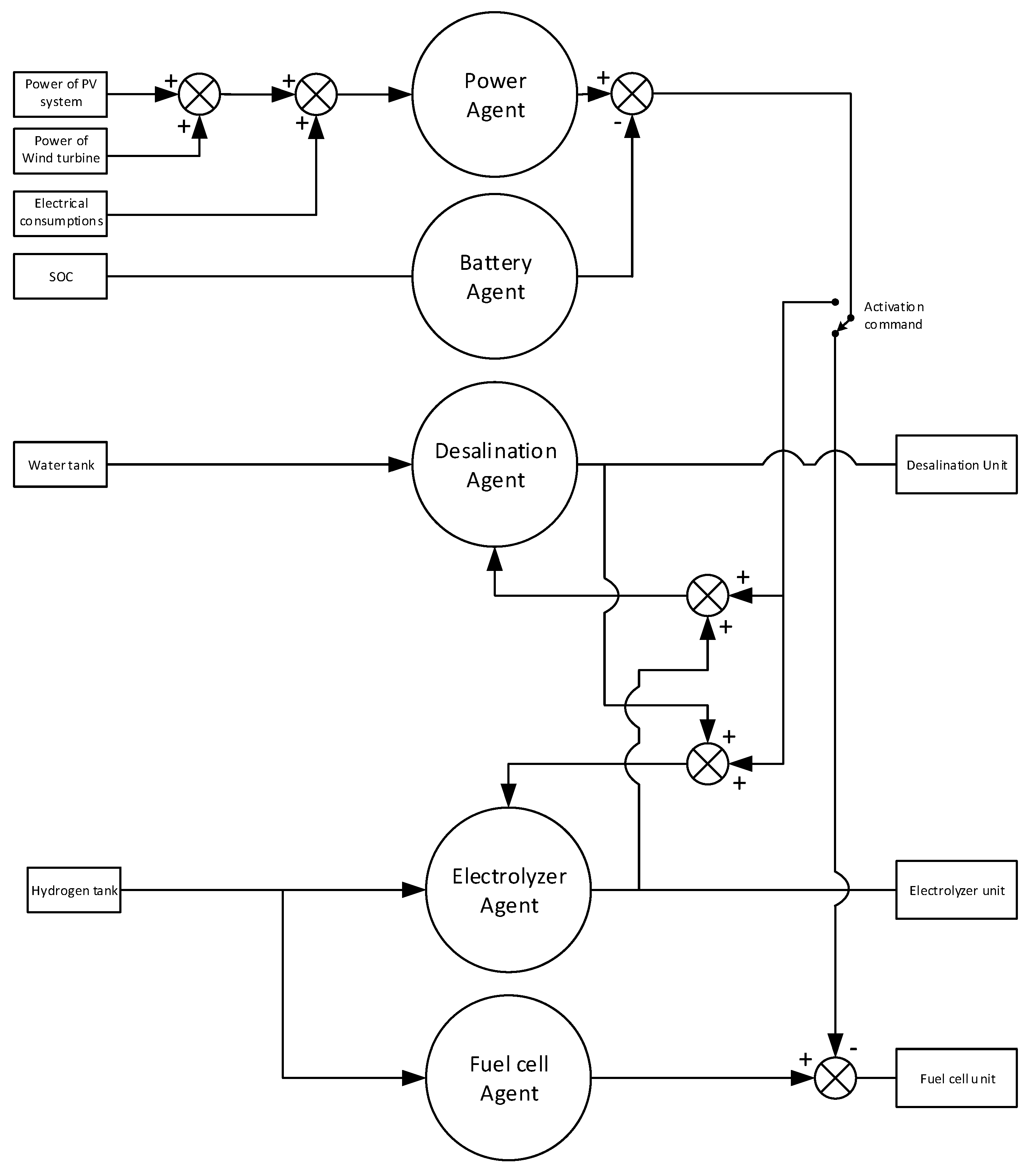
A MAS was used to represent the different characteristics of each component of the microgrid and their interaction in the microgrid. The MAS of the microgrid consisted of five intelligent agents and the Percepts, Actions, Goals and the Environment (PAGE) where the agents act are presented in Table 2. The five agents of the microgrid were the Power agent, the Battery agent, the Desalination agent, the Electrolyzer agent and the Fuel cell agent. In this MAS, each agent has different goals and the DEMS make decisions in order to meet the variable energy conditions such as the intermittency of renewable energy sources (RES) and to fulfil the load, potable water and fuel for transportation demands. The objective of MAS-DEMS is the effective operation of microgrid through the optimal usage of the distributed energy generation sources and storage units. The topology of MAS is presented in Figure 2. Figure 3 illustrates the DEMS blog diagram of the MAS-DEMS architecture.
3.2. Intelligent Agents Overview
3.2.1. Power Agent
The Power agent is a simple reflex agent which represents the PV system, the wind energy system and the electrical energy demand. The agent monitors the power generation of the PVs and wind turbine and calculates the energy balance of the system using Equation (1). The preference of the agent was to maximize the energy production of the renewable generators:
where Ppv is the average power generation of the PVs for a time period of one hour, Pwind is the average power generation of the wind turbine for a time period of one hour, Pload is the average electrical power demand for a time period of one hour and t is the time period and it is equal to one hour (1 h).
3.2.2. Battery Agent
The Battery agent was a simple reflex-agent which represents the battery bank. This agent took as input the state of charge (SOC) of the battery bank at any time step and controls the charging and discharging of the battery bank. The preference of this agent was to cover the load demand when the RES could not provide enough power and to protect the battery bank which depends directly to the battery SOC. The SOC should be kept between a minimum and maximum limit (Equation (2)). In this study, minimum depth of discharge (DOD) of the battery bank was set at 20% (Equation (3)) [52]:
where:
The Battery agent uses a utility function for the battery bank which was related to the variation rate of the battery energy (Equation (4)) [53]:
where is the nominal energy capacity of the battery bank as defined by the manufacturer and is the operating energy capacity.
3.2.3. Desalination Agent
The Desalination agent was a goal-based agent which represented the desalination unit. The preferences of the agent were to cover the potable water demand and not allow the water tank get empty. It has been investigated that the desalination unit can operate within a wide load range (variable load operation), offering flexibility and higher efficiencies than a conventional desalination unit (full load operation) [3]. Therefore, the desalination unit was controlled by the Desalination agent to operate at variable load, taking into consideration that its minimum power could be equal to 30% of the nominal power [54]. When the water tank gets full then the desalination agent deactivates the desalination unit. In other cases, the desalination agent decides about the operation point of the desalination unit by using a utility function for the desalination unit which was related to the variation rate of the desalination unit’s power consumption with preference to maximize the potable water production (Equation (5)) [54]:
where is the nominal power of the desalination unit and is its average power for one hour operation.
3.2.4. Electrolyzer Agent
The Electrolyzer agent was a goal-based agent which represented the electrolyzer unit. The preferences of the agent are to cover the hydrogen consumption and to ensure an amount of hydrogen in the hydrogen tank (). The electrolyzer unit could produce hydrogen even when it operated at variable load [49]. Therefore, it was considered to be able to produce hydrogen only when it operated above the 30% of the nominal power [15]. The electrolyzer was deactivated by the agent when the hydrogen tank capacity gets its maximum. The agent decides about the operation point of the electrolyzer by using a utility function for the electrolyzer unit which was related to the variation rate of the electrolyzer’s power consumption with preference to maximize the hydrogen production (Equation (6)):
where is the nominal power of the electrolyzer and is its average power for one hour operation.
3.2.5. Fuel Cell Agent
The Fuel cell agent was a model-based reflex agent which represented the fuel cell unit. The preference of this agent is to cover the electrical demand when the power from the energy sources was not enough. The fuel cell could operate at variable load [47] and the minimum power () was considered equal to 30% of the nominal power [15]. The Fuel cell agent determines the optimum operation point of the fuel cell () with the preference of not consuming high amounts of the stored hydrogen.
3.3. Game Theory for MAS
3.3.1. Energy Control Games
The intelligent agent system has as main priority to fulfil the household electrical consumptions. So, the components that affect the energy management and control of the microgrid are the electrolyzer, the desalination unit, the battery bank and the fuel cell. The game theory was used to develop an optimized EMS in order to handle the energy dispatch of RES power production and to optimize the utility functions of the agents. To this end, the energy management problem was separated into two parts, depending on the surplus energy (ΔE) and the available power capacity of the battery bank. When the power production from the RES and the available power from the battery bank can cover the household energy consumptions, then the desalination agent and the electrolyzer agent activate the desalination unit and the electrolyzer, respectively. In the opposite case, only the fuel cell unit is activated. Therefore, two energy control games have been established for the EMS, where the first game is activated when the ΔE + EBAT > 0 and the second game is activated when ΔE + EBAT < 0.
First Game Model
In the first game model, the desalination agent and the electrolyzer agent were two non-cooperative agents, since they attempted to exploit as more energy as possible in order to produce as more potable water and hydrogen, respectively. Therefore, a non-cooperative energy control game has been established in which the two players/agents must negotiate and determine the set of powers to satisfy both utility functions. The non-cooperative game can be defined as:
In this game, the battery bank operates as a buffer in order to meet the energy demands of the desalination and electrolyzer agent. Therefore, the utility functions of the desalination agent and electrolyzer agent are modified with the support of the utility function of the battery agent. Furthermore, the set of powers are affected by various factors such as the SOC of the battery bank, the energy production by renewable energy sources, the stored potable water and the stored hydrogen. Therefore, weights coefficients were added to the utility functions in order to determine this effect in each time step. The new two utility functions are:
where and are the weights coefficients for the desalination unit and the battery bank and the sum of the two weights equals to one (), and, similarly:
where and are the weights coefficients for the electrolyzer unit and the battery bank and the sum of the two weights equals to one ().
In this game, the Nash equilibrium achieves the set of powers which are the optimum power of the desalination unit and the electrolyzer. Nash equilibrium is the crossing point of the best response functions for the desalination unit and the electrolyzer which is the solution of two differential equations defined as:
Taking into account the Equation (10), then the solutions of Equation (9) are the best responses, which refers to the power that maximizes the utility function of one player/agent taking the other player’s power as given.
where , and t is the time period and it is equal to one hour (1 h).
Therefore, the best response functions can be written as Equations (11) and (12):
It must be noted that the Nash equilibrium always exist for this game [26]. The weights coefficients ( and ) were determined automatically in each time step, using the Fuzzy Logic theory. To this end, a Fuzzy Logic system was developed which was based on Mamdani Fuzzy interface using min-max method of fuzzification and centroid method of defuzzification. The implementation was performed with the software package Matlab using the Fuzzy Logic Toolkit. The developed Fuzzy Logic system is a decision-making unit based on typical fuzzy rules which utilize the if-then else rules and a problem with N data have the following form:
where are the K decisions for a N data decision problem, and represents the fuzzy set.
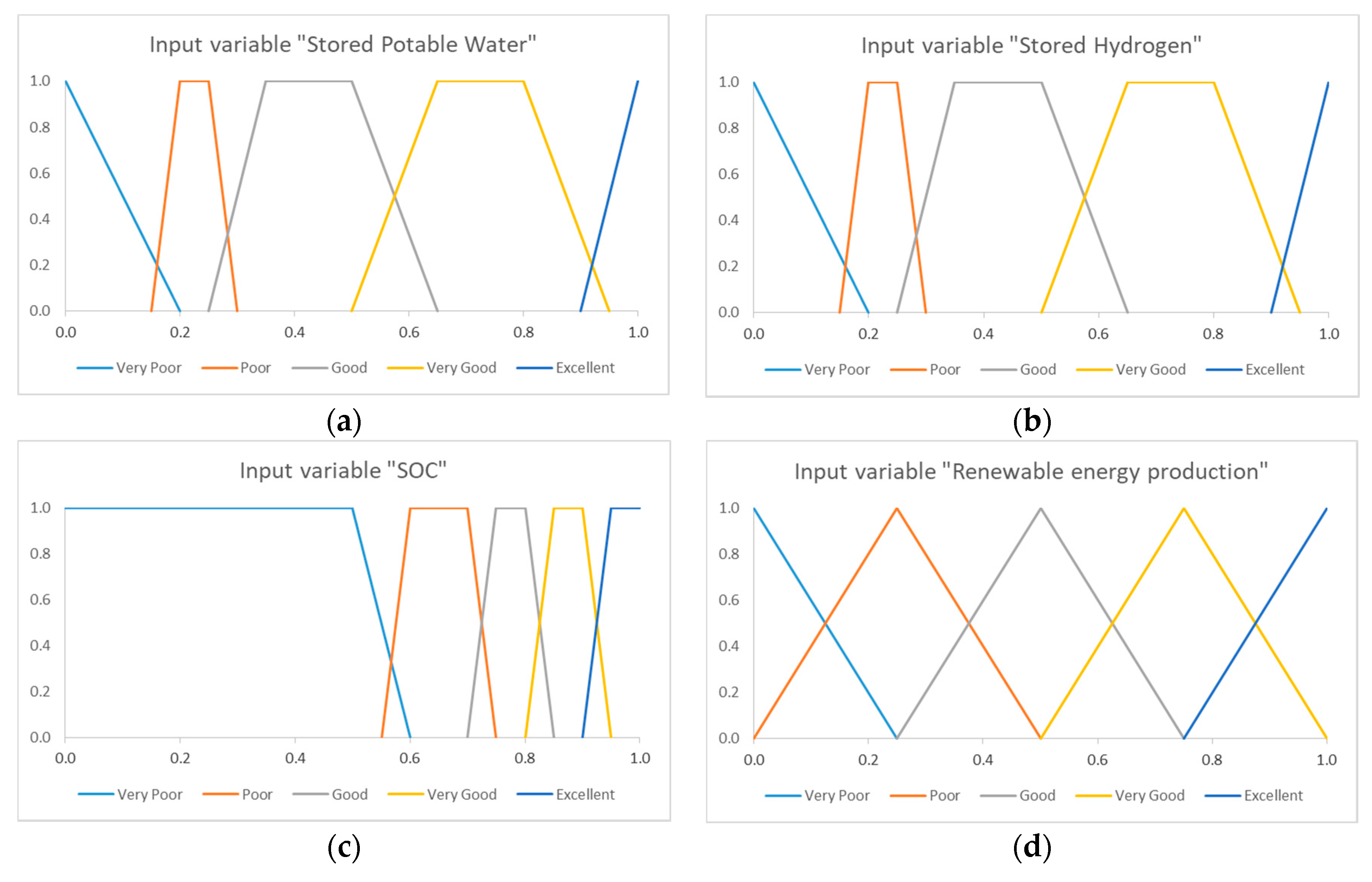
The developed Fuzzy Logic system had four inputs and two outputs. The inputs were the stored potable water, the stored hydrogen, the produced energy by RES and the SOC of the battery bank. The different inputs were quantified into numbers ranging from zero (very poor) to one (excellent). A membership function of each input was developed and used the linguistic variables Very Poor, Poor, Good, Very Good and Excellent. The membership curve for each input is presented in Figure 4.
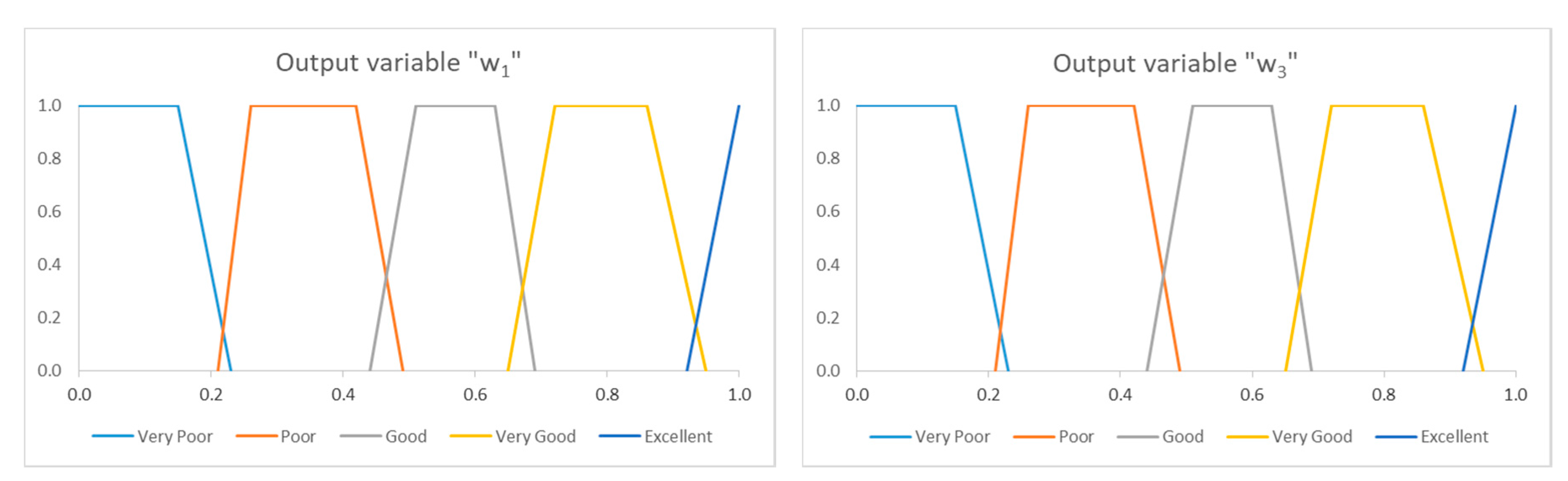
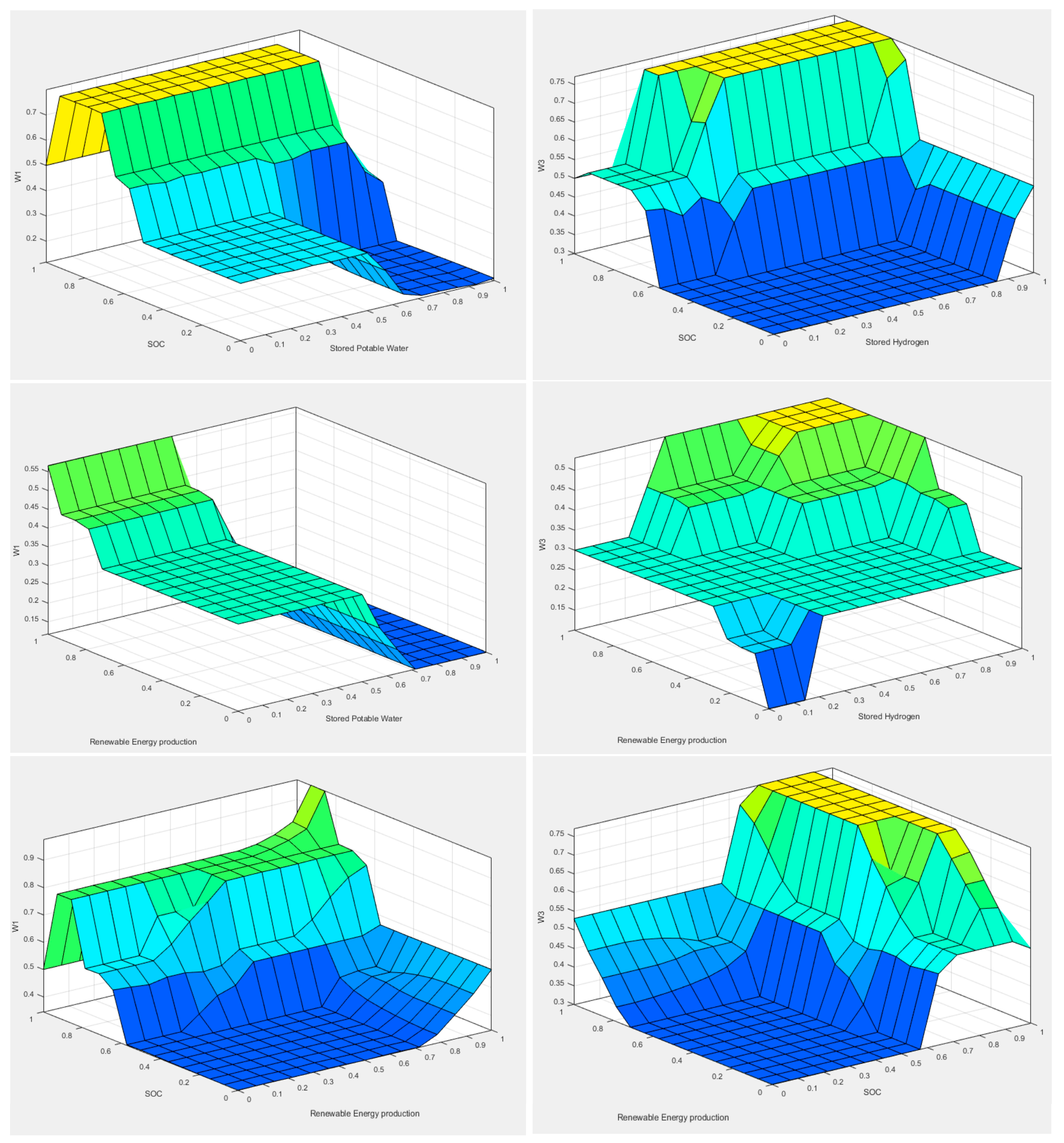
Since the fuzzy logic system has been developed, and can be calculated. They are numerical values which correspond to a fuzzy set and they are ranging from zero to one. The input variables “Stored Potable Water”, “SOC” and “Renewable energy production” used for the weight . The same input variables with one exception used for the weight . The exception is that instead of “Stored Potable Water”, the input variable “Stored Hydrogen” is considered. Figure 5 shows the membership functions of the outputs. All the membership functions of the fuzzy logic routines were designed using the control surfaces (Figure 6) based on the experience of the research team. The rules for each of the routines were developed based on the previous knowledge and the experience of the members of the research team [17].
Second Game Model
The second game was a cooperative game as the fuel cell agent and the battery agent communicate and cooperate in order to meet the load demand. In this game, the produced energy from RES and the battery capacity is not enough to cover the load demand and the fuel cell was used as a backup energy producer in order to guarantee zero energy deficit.
The energy management problem can be configured as a cooperative game which purpose is to find a pair of powers , seeking to maximize agents’ revenues taking into consideration the following constraints:
Therefore, the cooperative energy management problem has been transformed into an optimization problem and can be defined as:
where and denote the revenue of the Fuel cell agent and Battery agent, respectively.
At first, the battery agent chooses its action (the available energy of the battery is supplied to the grid but the minimum SOC cannot drop under 20%) and then the fuel cell agent determines the operation point of the fuel cell (must cover the remaining power demand).
4. Optimization Parameters
The optimum design of the system means that the investor wants to build a system with the lowest Net Present Cost (NPC) and to fulfil, at the same time, all the technical constraints which are required to ensure the system’s stability and safe operation. The technical constraints used were:
- All household electrical consumptions must be covered at 100% throughout the year.
- The potable water tank must never get empty.
- The hydrogen tank must never get empty.
- The stored potable water and hydrogen at the end of the year ought to be equal or higher than the stored water and hydrogen at the beginning of the year.
- The battery bank ought not to be deep discharged. The SOC of the battery bank should not drop under 20% at any time.
Therefore, a cost function was formulated in order to get the proper sizing of the components. The minimum of this cost function equals to the best system for a 20 year investment period. The prices of the equipment were in accordance with market prices. The technical constraints are ensured as penalties which are added to cost function when one or more technical constraint is not met. The penalties equal to zero when the technical constraints are satisfied. Otherwise, a huge amount is added in the cost function (in the present study, each penalty equals to 1 million euros).
The cost function (CF) to be minimized is presented in Equation (13):
where NPC is the Net Present Cost for a 20 year-long operation. The calculation of NPC was carried out in accordance with market prices of the several components of the system. In addition, the operation and maintenance cost was included in the calculations and an interest rate equal to 6% was considered. Moreover, it is decided to change the battery bank every seven years. is the battery penalty added if the SOC becomes lower than 20% or the annual number of charge cycles exceed the maximum annual permissible cycles which were calculated for 7 years of the battery bank, A full single charge/discharge cycle is considered when the battery discharges to the DOD set and then get charged to 100%. In our calculations, a full charge/discharge cycle may be comprised by several partial cycles which add up to one full single charge/discharge. is the hydrogen penalty added if the metal hydride tank becomes empty. Pw is the water penalty added if the water tank becomes empty. Pwt is the water tank penalty added if the stored water at the end of the year is less than at the beginning of the year and is the metal hydride tank penalty added if the stored hydrogen at the end of the year is less than at the beginning of the year.
5. Simulation and Results
5.1. Simulation Results
The study took place for an APM installed at a small island in the Cyclades complex in the Aegean Sea of Greece and typical meteorological data of the area have been used for the simulations. The settlements was comprised of three households with four residents each [15]. All the electrical devices considered have an energy consumption rating of A/A+. The average energy consumption was 62.5 kWh per day and the peak load demand was 7.72 kW. The potable water needs (drinking, bathing, cooking and laundry) at daily basis were considered to be 2.88 m3. In addition, four hybrid fuel cell-battery scooters were considered to cover 50 km each per day. So, the daily fuel consumption was estimated at 2.4 Nm3H2. The scooters were refilled every day in the afternoon. The simulation of the system lasted for one year and the simulation time step was at 1 h. Furthermore, the variables’ values of the system’s components and the maximum annual number of cycles are considered in system data. According to the manufacturer, the life cycle time for a depth of discharge equal to 80% and for an ambient temperature equal to 20 °C, comprises of 1640 charge cycles. Since in the area where the microgrid is assumed to be installed, the actual ambient temperatures exceed this limit of 20 °C, it is assumed that the life cycle time will be reduced to 870 charge cycles. Furthermore, according to [55], the actual battery lifetime in autonomous systems which incorporate renewable energy sources, is further reduced by about 17.5%. Moreover, the battery life time will be reduced by a factor equal to 30% for the safe operation of the microgrid and to ensure the reliable operation of the battery bank. Therefore, the total number of charge cycles is assumed to be 502 cycles (=870 cycles × 82.5% × 70%) and the average annual charge cycles for 7 years of operation of the battery bank were calculated to be 72 cycles on average and this was set as the maximum annual permissible cycles (Equation (13)). Using the above data, the autonomous polygeneration microgrid with the MAS-DEMS of Section 3 was sized using the PSO method and the optimization parameters of Section 4. The optimization variables along with the optimal values are presented in Table 3.
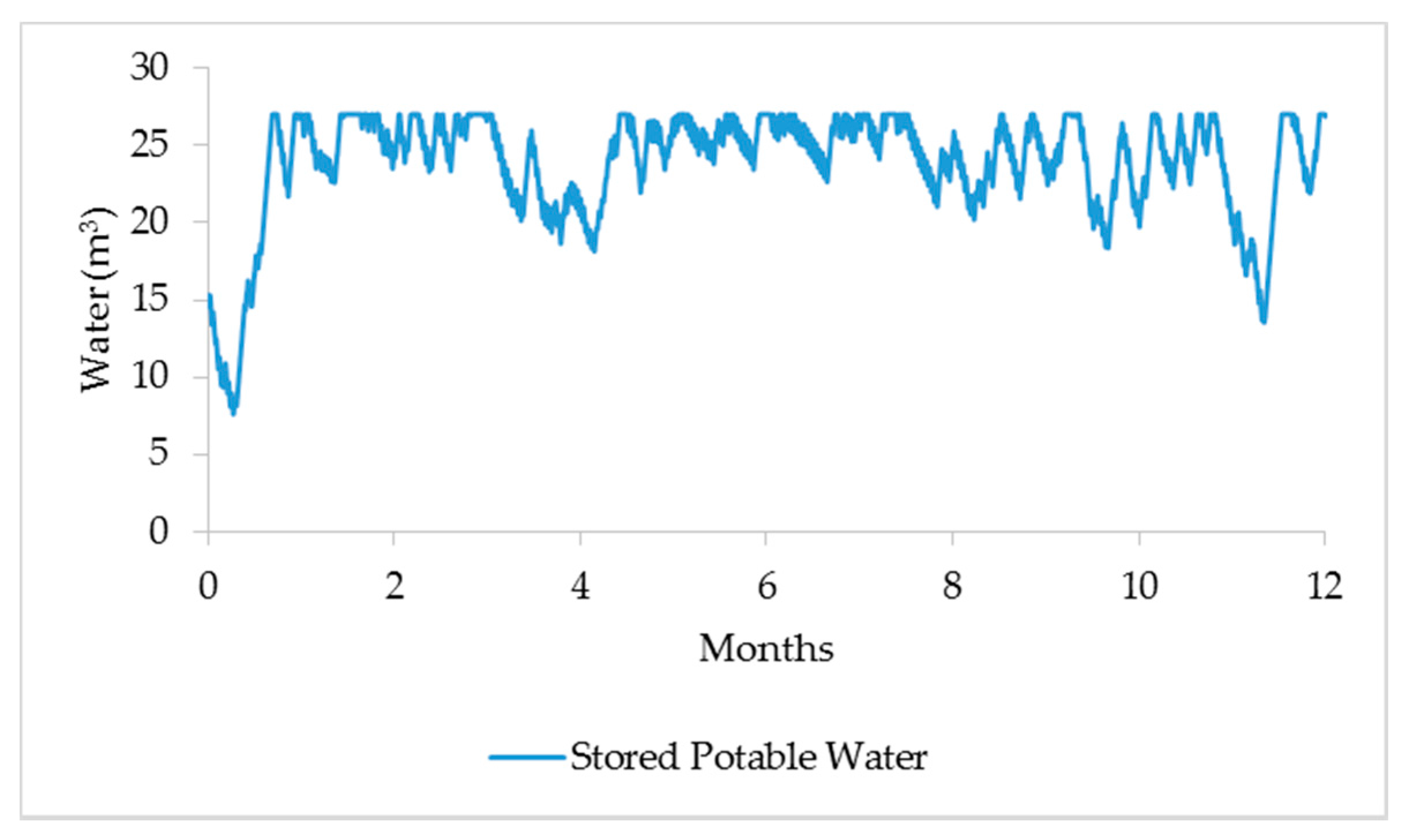
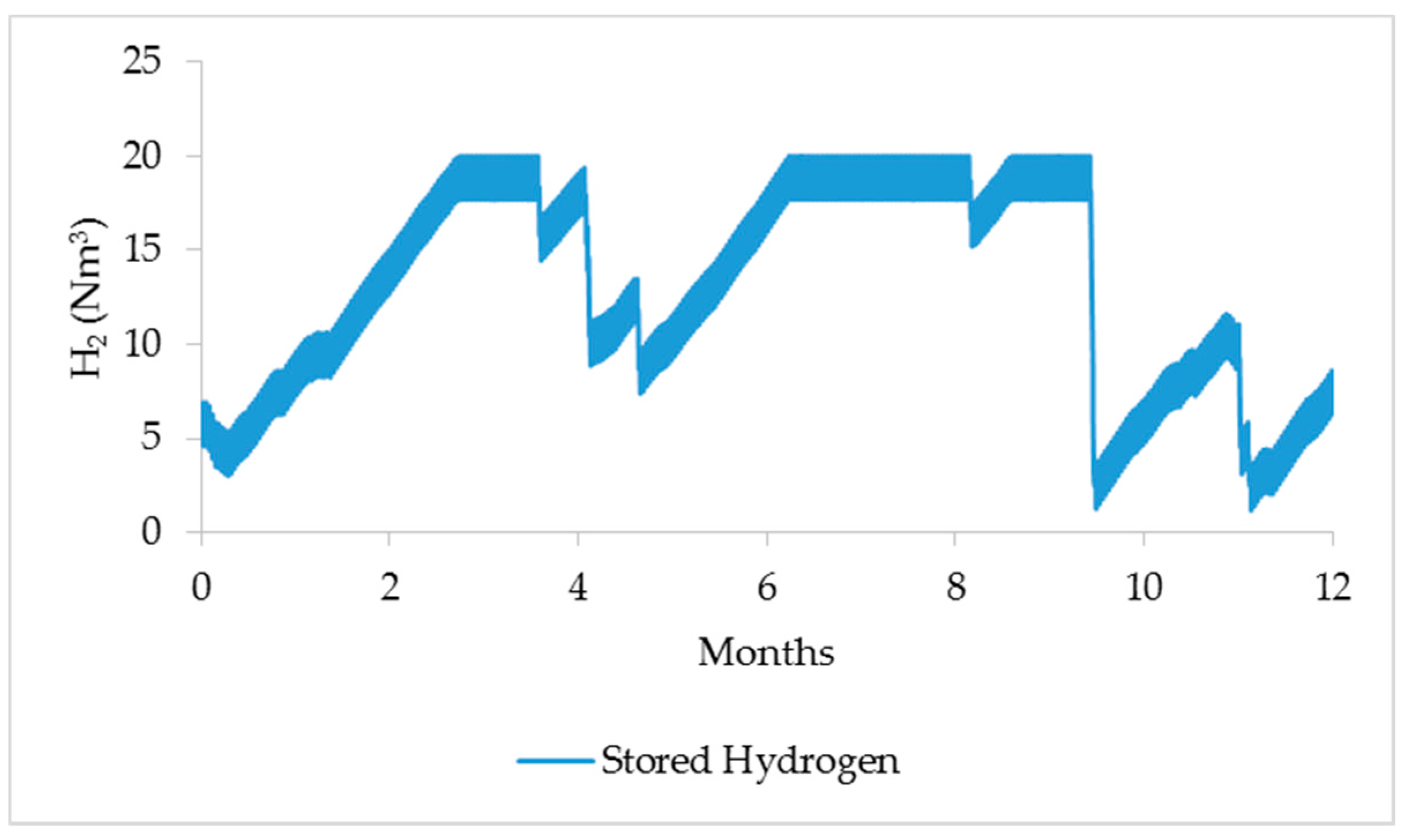
The annual variation of the potable water and hydrogen are presented in Figure 7 and Figure 8, respectively. It is obvious that the tanks never become empty and the stored water and hydrogen were at the end of the year higher than that at the beginning of the year. The SOC of the battery bank during the year is presented in Figure 9, from which it becomes clear that it never falls under 20%, as the lowest SOC observed was equal to 20.39%. The annual charge cycles were calculated at 49 cycles, obviously below the maximum permissible charge cycles (calculated to 72 cycles), thus ensuring the safe operation of the system and the reliable operation of the battery bank. The annual energy production by PVs and wind turbine was much higher than the fuel cell unit’s energy production, which was only operational for 67 h to support the grid from collapsing.
In order to present the performance of the MAS-DEMS based on game theory, two typical days were chosen. The first typical day was a summer day where the energy production by RES was high, (see Figure 10). Therefore, the energy productions by PVs and wind turbine could cover the load demand. The desalination agent and the electrolyzer agent were competing and the optimal operation point of the desalination unit and electrolyzer were estimated (the crossing point of Equations (11) and (12)). As a result, the desalination unit and the electrolyzer operated almost during the whole day, either in partial or full mode. Furthermore, the fuel cell unit was not required and the fuel cell agent kept it deactivated.
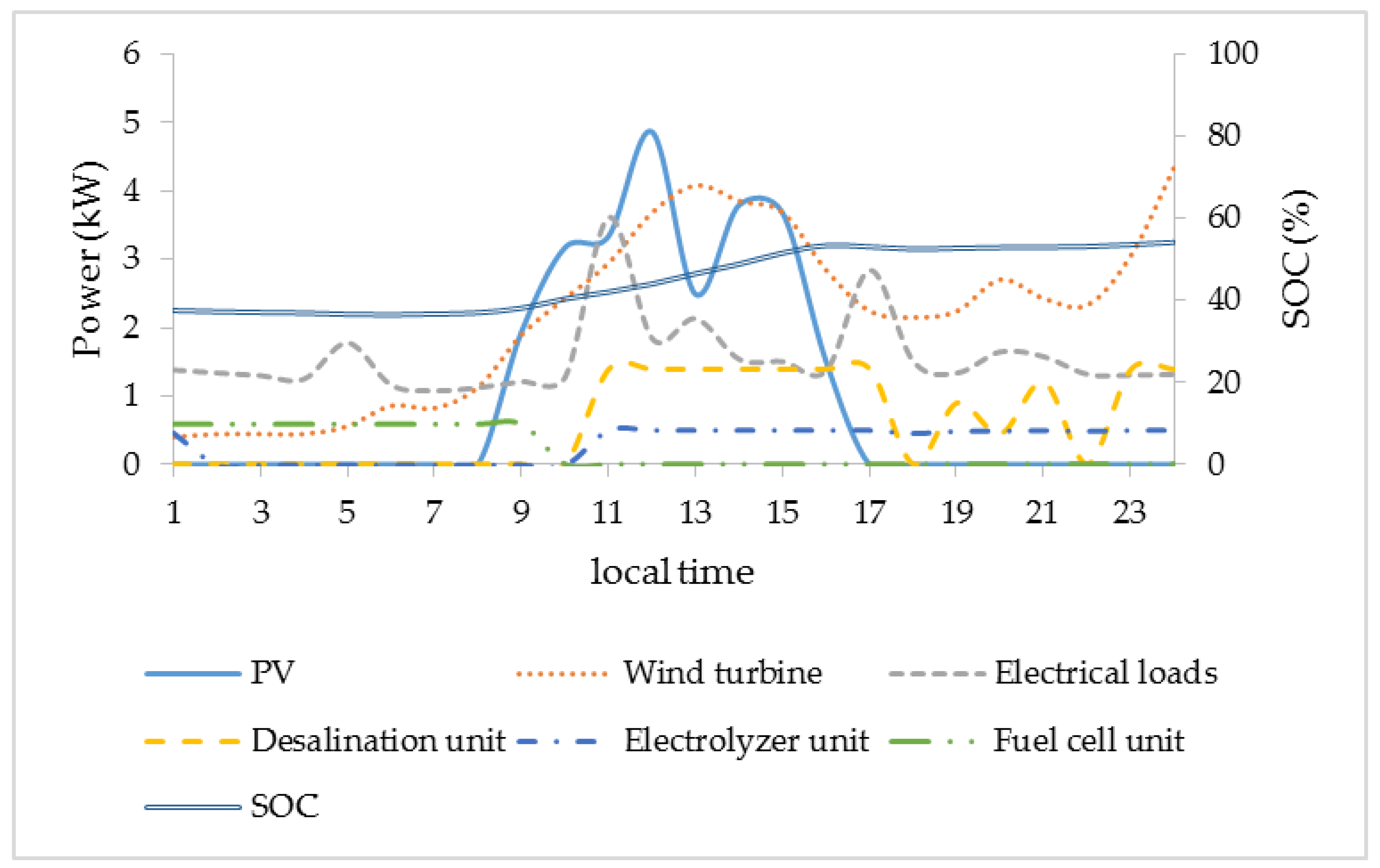
In Figure 11, the power variations during the second day are presented. It was a day where the energy production by RES was very low. At the beginning of the day, the SOC was low, and its power with the power production from PVs and the wind turbine was not enough to cover the load demand. The fuel cell agent activated the fuel cell unit (which operated mostly during the night) in order to cover the electrical needs and to protect the battery bank from a deep discharge. When the solar and wind resources increased and could cover the electrical needs, the SOC showed a constant increase and the fuel cell turned off. Furthermore, the desalination unit and the electrolyzer started producing potable water and hydrogen, respectively.
5.2. Microgrid Performance Evaluation
A MAS-DEMS based on computational intelligence (Fuzzy Cognitive Maps-FCM) for APM was presented in [19]. A comparison between this system and the system proposed in this paper, based on game theory, was carried out. In order to make a fair comparison between the two systems, both of them used the same APM topology and had the same electrical demand and water and fuel needs. The comparison of the two microgrids proved that the present one using MAS-DEMS employing Game Theory showed lower cost by 1.62%. The total cost of the microgrid which used MAS-DEMS based on Game Theory was 156,287 € while the total cost of the microgrid which used MAS-DEMS based on FCM was 158,856 €.
Furthermore, a comparison between the two microgrids based on their performances were made. The performance of each microgrid was assessed based on its power losses and the battery bank was not included as it was used as a backup power source [34]. Equation (14) was used to evaluate the power losses of the microgrids:
where Pcons is the total energy consumption (household energy demand, desalination unit and electrolyzer) and Pprod is the total energy production (PVs, wind turbine and fuel cell).
The power losses percentage of the MAS-DEMS based on game theory calculated at 3.44% while the MAS-DEMS based on FCM presented 5.91%. Furthermore, the annual charge cycles in the microgid that incorporates the MAS-DEMS based on FCM were 53 cycles, while the cycles of the microgrid that incorporated the MAS-DEMS based on game theory were 49 cycles. Therefore, the MAS-DEMS based on game theory reduces the annual charge cycles by almost 7%, while also using a battery bank of smaller capacity than the MAS-DEMS on FCM. Therefore, it is clear that the proposed microgrid with MAS-DEMS based on game theory has higher efficiency and less power losses after one year operation, showing that it could perform satisfactorily with better results in economic terms.
6. Conclusions
This paper deals with the design and the performance analysis of a multi agent system that has successfully been applied to the decentralized energy management problem of autonomous polygeneration microgrids. The proposed energy management system relies on a game theory approach. The MAS-DEMS have been designed and investigated through simulation for the efficient energy handling and the satisfactory management of the microgrid covering all its electrical, water and transportation fuel needs. The developed MAS consists of five agents, some of which either compete or cooperate with each other, according to the level of the energy produced by the RES and the energy stored to the battery bank, in order to accomplish optimal energy management and control for the microgrid operation. The competition or the cooperation between the agents was expressed as a non-cooperative or a cooperative game, respectively. The benefits of the game theory approach in the energy management were used for exploring of the optimum solutions of games with the assistance of Nash equilibrium.
The proposed MAS-DEMS was compared with a previously developed MAS-DEMS that used computational intelligence algorithms (fuzzy cognitive maps) instead of game theory approach. The results obtained from this comparison shoed that the present system utilizes the units of the microgrid better, a fact that in turn led to a higher efficiency, lower power losses and a lower cost for a 20 years investment period. In conclusion, the obtained results clearly show that a game theoretic approach for MAS-DEMS is feasible and guarantees satisfactory results in terms of operation for autonomous polygeneration microgrids. Future work will concentrate on the experimental investigation of the proposed MAS-DEMS in the microgrid installed at Agricultural University of Athens, Greece, taking into account more technical grid constraints.
Acknowledgments
The present research work was conducted within the research project “Development of Energy Management Systems for the Design and Control of Autonomous Hybrid Systems and Microgrids, Incorporating Computational Intelligence Techniques”, funded by the Scholarship Foundation of Greece in the context of “RESEARCH PROJECTS FOR EXCELLENCE IKY/SIEMENS”.
Author Contributions
All authors contributed to the survey literature. Christos-Spyridon Karavas developed the proposed MAS-DEMS system and performed the various simulations and the analysis of the proposed game theoretic architecture. He also wrote the basic part of the paper. Konstantinos Arvanitis and George Papadakis jointly supervised the overall work and the overall structure of the paper, and they contributed with their experience in the concept, design, supervision and analysis of the simulation results.
Conflicts of Interest
The authors declare no conflict of interest.
Nomenclature
| CF | Cost function |
| DOD | Depth of discharge |
| Pb | Battery penalty |
| EBAT | Operating energy capacity |
| EBAT,max | Nominal energy capacity of the battery bank |
| PDES | The operation power of the desalination unit |
| PDES,nom | The nominal power of the desalination unit |
| PELE | The operation power of the electrolyzer unit |
| PELE,nom | The nominal power of the electrolyzer unit |
| PFUEL | The operation power of the fuel cell unit |
| PH2 | Hydrogen penalty |
| PH2T | Metal hydride tank penalty |
| Pload | Power consumption |
| Ploss | Power losses |
| Ppv | Power generation by the photovoltaic array |
| Pprod | Total energy production |
| Pcons | Total energy consumption |
| Pw | Water penalty |
| Pwind | Power generation of the wind turbine |
| Pwt | Water tank penalty |
| SOC | State of charge |
| StoredH2 | The hydrogen stored in the metal hydride tank |
| ΔE | Surplus energy |
Abbreviations
| APM | Autonomous polygeneration microgrid |
| CEMS | Centralized energy management system |
| DEMS | Decentralized energy management system |
| EMS | Energy management system |
| FCM | Fuzzy cognitive maps |
| ΙΑ | Intelligent agent |
| MAS | Multi agent system |
| NPC | Net present cost |
| PAGE | Percepts, actions, goals and environment |
| PSO | Particle swarm optimization |
| RES | Renewable energy sources |
References
- Chen, C.; Wang, J.; Qiu, F.; Zhao, D. Resilient distribution system by microgrids formation after natural disasters. IEEE Trans. Smart Grid 2016, 7, 958–966. [Google Scholar] [CrossRef]
- Karavas, C.-S.; Papadakis, G. Renewable energy driven small-scale sea water reverse osmosis desalination systems: A survey. J. Fundam. Renew. Energy Appl. 2017, 7, e115. [Google Scholar] [CrossRef]
- Dimitriou, E.; Mohamed, E.S.; Karavas, C.; Papadakis, G. Experimental comparison of the performance of two reverse osmosis desalination units equipped with different energy recovery devices. Desalinat. Water Treat. 2014, 55, 1–8. [Google Scholar] [CrossRef]
- Kosmadakis, G.; Landelle, A.; Lazova, M.; Manolakos, D.; Kaya, A.; Huisseune, H.; Karavas, C.-S.; Tauveron, N.; Revellin, R.; Haberschill, P.; et al. Experimental testing of a low-temperature organic Rankine cycle (ORC) engine coupled with concentrating PV/thermal collectors: Laboratory and field tests. Energy 2016, 117, 222–236. [Google Scholar] [CrossRef]
- Franzitta, V.; Curto, D.; Rao, D.; Viola, A. Hydrogen production from sea wave for alternative energy vehicles for public transport in Trapani (Italy). Energies 2016, 9, 850. [Google Scholar] [CrossRef]
- Kyriakarakos, G.; Dounis, A.I.; Rozakis, S.; Arvanitis, K.G.; Papadakis, G. Polygeneration microgrids: A viable solution in remote areas for supplying power, potable water and hydrogen as transportation fuel. Appl. Energy 2011, 88, 4517–4526. [Google Scholar] [CrossRef]
- Hatziargyriou, N.; Asano, H.; Iravani, R.; Marnay, C. Microgrids. IEEE Power Energy Mag. 2007, 5, 78–94. [Google Scholar] [CrossRef]
- Katiraei, F.; Iravani, R.; Hatziargyriou, N.; Dimeas, A. Microgrids management. IEEE Power Energy Mag. 2008, 6, 78–94. [Google Scholar] [CrossRef]
- Jiang, Q.; Xue, M.; Geng, G. Energy management of microgrid in grid-connected and stand-alone modes. IEEE Trans. Power Syst. 2013, 28, 3380–3389. [Google Scholar] [CrossRef]
- Lidula, N.W.A.; Rajapakse, A.D. Microgrids research: A review of experimental microgrids and test systems. Renew. Sustain. Energy Rev. 2011, 15, 186–202. [Google Scholar] [CrossRef]
- Meng, L.; Sanseverino, E.R.; Luna, A.; Dragicevic, T.; Vasquez, J.C.; Guerrero, J.M. Microgrid supervisory controllers and energy management systems: A literature review. Renew. Sustain. Energy Rev. 2016, 60, 1263–1273. [Google Scholar] [CrossRef]
- Hatziargyriou, N.; Dimeas, A.; Tsikalakis, A. Centralized and decentralized control of microgrids. Int. J. Distrib. Energy Resour. 2005, 1, 197–212. [Google Scholar]
- Conti, S.; Nicolosi, R.; Rizzo, S.; Zeineldin, H. Optimal dispatching of distributed generators and storage systems for MV islanded microgrids. IEEE Trans. Power Deliv. 2012, 27, 1243–1251. [Google Scholar] [CrossRef]
- Etemadi, A.H.; Davison, E.J.; Iravani, R. A decentralized robust control strategy for multi-DER microgrids—Part I: Fundamental concepts. IEEE Trans. Power Deliv. 2012, 27, 1843–1853. [Google Scholar] [CrossRef]
- Karavas, C.-S.; Kyriakarakos, G.; Arvanitis, K.G.; Papadakis, G. A multi-agent decentralized energy management system based on distributed intelligence for the design and control of autonomous polygeneration microgrids. Energy Convers. Manag. 2015, 103, 166–179. [Google Scholar] [CrossRef]
- Torreglosa, J.; García, P.; Fernández, L.; Jurado, F. Hierarchical energy management system for stand-alone hybrid system based on generation costs and cascade control. Energy Convers. Manag. 2014, 77, 514–526. [Google Scholar] [CrossRef]
- Kyriakarakos, G.; Dounis, A.I.; Arvanitis, K.G.; Papadakis, G. A fuzzy logic energy management system for polygeneration microgrids. Renew. Energy 2012, 41, 315–327. [Google Scholar] [CrossRef]
- Kyriakarakos, G.; Dounis, A.I.; Arvanitis, K.G.; Papadakis, G. A fuzzy cognitive maps-petri nets energy management system for autonomous polygeneration microgrids. Appl. Soft Comput. 2012, 12, 3785–3797. [Google Scholar] [CrossRef]
- Chang, H.-H. Genetic algorithms and non-intrusive energy management system based economic dispatch for cogeneration units. Energy 2011, 36, 181–190. [Google Scholar] [CrossRef]
- Anh, H.P.H. Implementation of supervisory controller for solar PV microgrid system using adaptive neural model. Int. J. Electr. Power Energy Syst. 2014, 63, 1023–1029. [Google Scholar] [CrossRef]
- McArthur, S.D.; Davidson, E.M.; Catterson, V.M.; Dimeas, A.L.; Hatziargyriou, N.D.; Ponci, F.; Funabashi, T. Multi-agent systems for power engineering applications—Part I: Concepts, approaches, and technical challenges. IEEE Trans. Power Syst. 2007, 22, 1743–1752. [Google Scholar] [CrossRef] [Green Version]
- McArthur, S.D.; Davidson, E.M.; Catterson, V.M.; Dimeas, A.L.; Hatziargyriou, N.D.; Ponci, F.; Funabashi, T. Multi-agent systems for power engineering applications—Part II: Technologies, standards, and tools for building multi-agent systems. IEEE Trans. Power Syst. 2007, 22, 1753–1759. [Google Scholar] [CrossRef] [Green Version]
- Kyriakarakos, G.; Piromalis, D.D.; Dounis, A.I.; Arvanitis, K.G.; Papadakis, G. Intelligent demand side energy management system for autonomous polygeneration microgrids. Appl. Energy 2013, 103, 39–51. [Google Scholar] [CrossRef]
- Dou, C.-X.; Wang, W.-Q.; Hao, D.-W.; Li, X.-B. MAS-based solution to energy management strategy of distributed generation system. Int. J. Electr. Power Energy Syst. 2015, 69, 354–366. [Google Scholar] [CrossRef]
- Fudenberg, D.; Tirole, J. Game Theory; The MIT Press: Cambridge, MA, USA, 1991; p. 12. [Google Scholar]
- Mei, S.; Wang, Y.; Liu, F.; Zhang, X.; Sun, Z. Game approaches for hybrid power system planning. IEEE Trans. Sustain. Energy 2012, 3, 506–517. [Google Scholar]
- Wang, Y.; Saad, W.; Han, Z.; Poor, H.V.; Başar, T. A game-theoretic approach to energy trading in the smart grid. IEEE Trans. Smart Grid 2014, 5, 1439–1450. [Google Scholar] [CrossRef]
- Khan, M.R.B.; Jidin, R.; Pasupuleti, J. Multi-agent based distributed control architecture for microgrid energy management and optimization. Energy Convers. Manag. 2016, 112, 288–307. [Google Scholar] [CrossRef]
- Agarwal, T.; Cui, S. Noncooperative Games for Autonomous Consumer Load Balancing over Smart Grid (GAMENETS); Springer: Berlin, Germany, 2012; pp. 163–175. [Google Scholar]
- Yin, H.; Zhao, C.; Li, M.; Ma, C.; Chow, M.-Y. A tem. IEEE Trans. Ind. Electr. 2016, 63, 4266–4277. [Google Scholar] [CrossRef]
- Stephens, E.R.; Smith, D.B.; Mahanti, A. Game theoretic model predictive control for distributed energy demand-side management. IEEE Trans. Smart Grid 2015, 6, 1394–1402. [Google Scholar] [CrossRef]
- Atzeni, I.; Ordóñez, L.G.; Scutari, G.; Palomar, D.P.; Fonollosa, J.R. Demand-side management via distributed energy generation and storage optimization. IEEE Trans. Smart Grid 2013, 4, 866–876. [Google Scholar] [CrossRef]
- Saad, W.; Han, Z.; Poor, H.V.; Basar, T. Game-theoretic methods for the smart grid: An overview of microgrid systems, demand-side management, and smart grid communications. IEEE Signal Process. Mag. 2012, 29, 86–105. [Google Scholar] [CrossRef]
- Russell, S. Artificial Intelligence: A Modern Approach Author: Stuart Russell, Peter Norvig; Prentice Hall: Upper Saddle River, NJ, USA, 2009. [Google Scholar]
- Wooldridge, M. An Introduction to Multiagent Systems; John Wiley & Sons: Hoboken, NJ, USA, 2009. [Google Scholar]
- Osborne, M.J.; Rubinstein, A. A Course in Game Theory; MIT Press: Cambridge, MA, USA, 1994. [Google Scholar]
- Aristidou, P.; Dimeas, A.L.; Hatziargyriou, N.D. Microgrid Modelling and Analysis Using Game Theory Methods, ICST E-Energy; Springer: Berlin, Germany, 2010; pp. 12–19. [Google Scholar]
- Ito, T.; Zhang, M.; Robu, V.; Fatima, S.; Matsuo, T. Advances in Agent-Based Complex Automated Negotiations; Springer: Berlin, Germany, 2009; Volume 233. [Google Scholar]
- Fakhrzad, M.; Khademi Zare, H. Combination of genetic algorithm with Lagrange multipliers for lot-size determination in multi-stage production scheduling problems. Expert Syst. Appl. 2009, 36, 10180–10187. [Google Scholar] [CrossRef]
- Fadaee, M.; Radzi, M. Multi-objective optimization of a stand-alone hybrid renewable energy system by using evolutionary algorithms: A review. Renew. Sustain. Energy Rev. 2012, 16, 3364–3369. [Google Scholar] [CrossRef]
- Wang, G.-G.; Hossein Gandomi, A.; Yang, X.-S.; Hossein Alavi, A. A novel improved accelerated particle swarm optimization algorithm for global numerical optimization. Eng. Comput. 2014, 31, 1198–1220. [Google Scholar] [CrossRef]
- Khare, A.; Rangnekar, S. A review of particle swarm optimization and its applications in solar photovoltaic system. Appl. Soft Comput. 2013, 13, 2997–3006. [Google Scholar] [CrossRef]
- Shakib, S.E.; Amidpour, M.; Aghanajafi, C. Simulation and optimization of multi effect desalination coupled to a gas turbine plant with HRSG consideration. Desalination 2012, 285, 366–376. [Google Scholar] [CrossRef]
- Clarke, D.P.; Al-Abdeli, Y.M.; Kothapalli, G. Multi-objective optimisation of renewable hybrid energy systems with desalination. Energy 2015, 88, 457–468. [Google Scholar] [CrossRef]
- Klein, A.; Beckman, A.; Mitchell, W.; Duffie, A.; Duffie, N.; Freeman, T. TRNSYS 17-a Transient System Simulation Program; Solar Energy Laboratory, University of Wisconsin: Madison, WI, USA, 2011. [Google Scholar]
- Mondol, J.D.; Yohanis, Y.G.; Norton, B. Optimising the economic viability of grid-connected photovoltaic systems. Appl. Energy 2009, 86, 985–999. [Google Scholar] [CrossRef]
- Kyriakarakos, G.; Dounis, A.I.; Arvanitis, K.G.; Papadakis, G. Design of a Fuzzy Cognitive Maps variable-load energy management system for autonomous PV-reverse osmosis desalination systems: A simulation survey. Appl. Energy 2017, 187, 575–584. [Google Scholar] [CrossRef]
- Yilanci, A.; Dincer, I.; Ozturk, H.K. Performance analysis of a PEM fuel cell unit in a solar-hydrogen system. Int. J. Hydrogen Energy 2008, 33, 7538–7552. [Google Scholar] [CrossRef]
- Barbir, F. PEM electrolysis for production of hydrogen from renewable energy sources. Sol. Energy 2005, 78, 661–669. [Google Scholar] [CrossRef]
- Wetter, M. GenOpt, Generic Optimization Program, User Manual, version 3; Lawrence Berkeley National Laboratory, University of California: Oakland, CA, USA, 2008. [Google Scholar]
- Thermal Energy System Specialists; TESS Libraries: Madison, WI, USA, 2008.
- Anuphappharadorn, S.; Sukchai, S.; Sirisamphanwong, C.; Ketjoy, N. Comparison the economic analysis of the battery between lithium-ion and lead-acid in PV stand-alone application. Energy Procedia 2014, 56, 352–358. [Google Scholar] [CrossRef]
- Shen, J.; Dusmez, S.; Khaligh, A. Optimization of sizing and battery cycle life in battery/ultracapacitor hybrid energy storage systems for electric vehicle applications. IEEE Trans. Ind. Inform. 2014, 10, 2112–2121. [Google Scholar] [CrossRef]
- Dimitriou, E.; Mohamed, E.S.; Kyriakarakos, G.; Papadakis, G. Experimental investigation of the performance of a reverse osmosis desalination unit under full-and part-load operation. Desalinat. Water Treat. 2015, 53, 3170–3178. [Google Scholar] [CrossRef]
- Bindner, H.; Cronin, T.; Lundsager, P.; Manwell, J.F.; Abdulwahid, U.; Baring-Gould, I. Lifetime Modelling of Lead Acid Batteries; University of Massachusetts: Boston, MA, USA, 2005. [Google Scholar]
Figure 1.
Schematic representation of the microgrid configuration.

Figure 2.
MAS topology.

Figure 3.
MAS-DEMS architecture.

Figure 4.
Membership curves for each input: (a) Stored Potable Water; (b) Stored Hydrogen; (c) SOC and (d) Renewable energy production.
Figure 4.
Membership curves for each input: (a) Stored Potable Water; (b) Stored Hydrogen; (c) SOC and (d) Renewable energy production.

Figure 5.
Output membership functions.

Figure 6.
Surfaces of the Fuzzy Logic system.

Figure 7.
Potable water in the water tank during the year.

Figure 8.
Hydrogen in the metal hydride tank during the year.

Figure 9.
Battery SOC during the year.
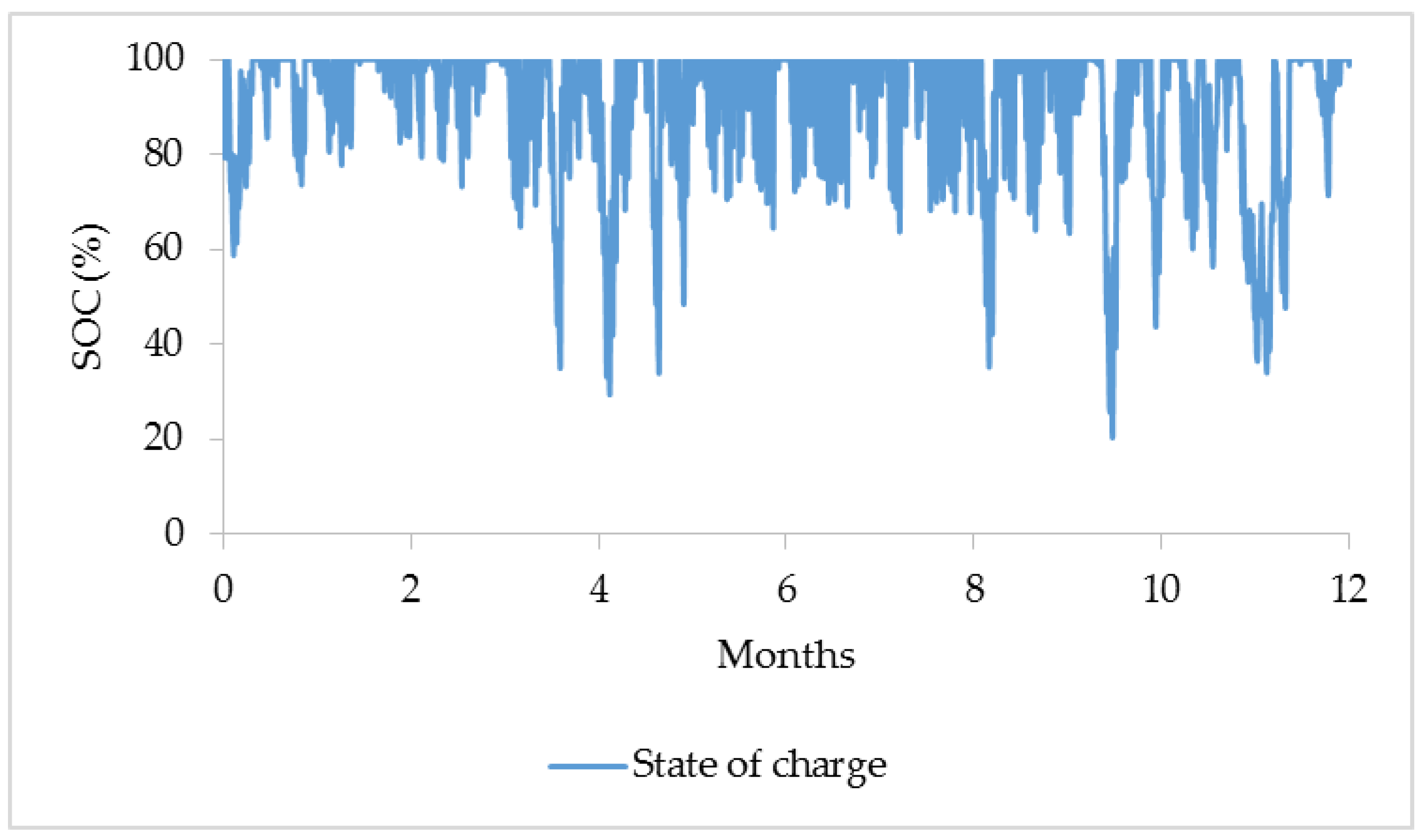
Figure 10.
Power variations during the sunny day.
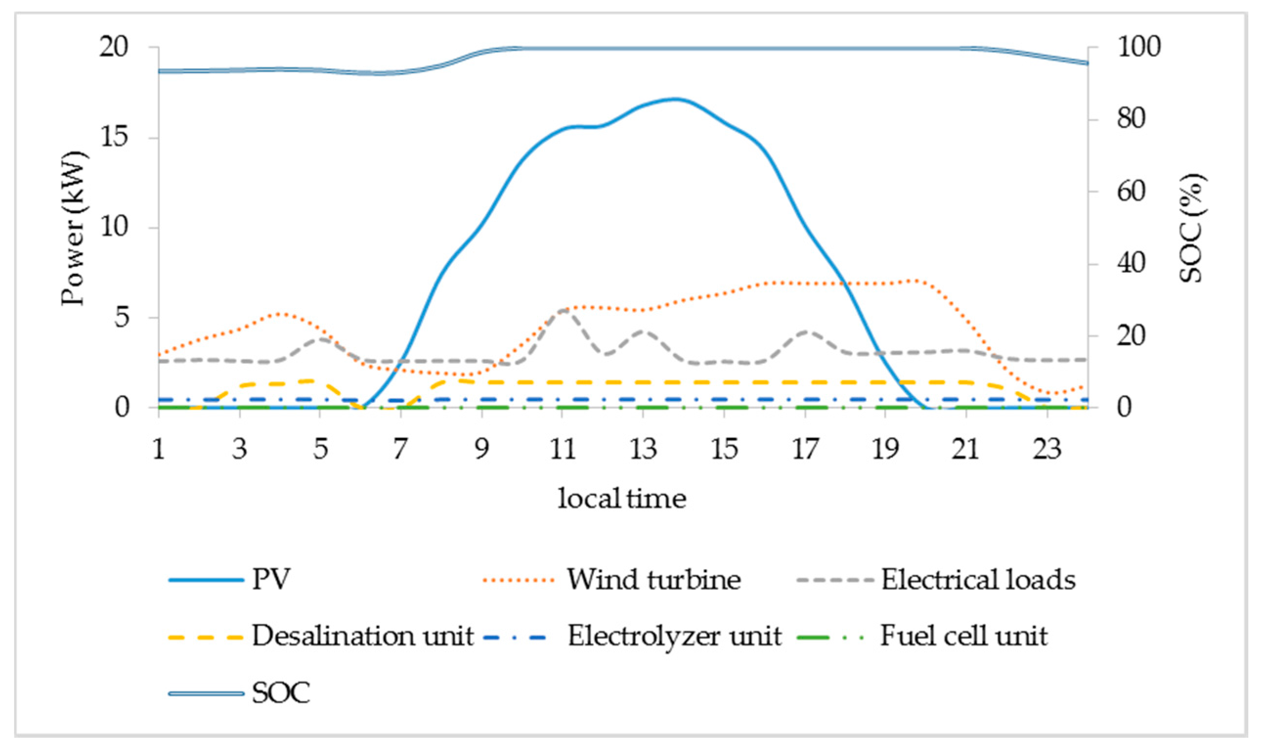
Figure 11.
Power variations during a winter day.

Table 1.
PSO settings.
| Topology | Lbest |
|---|---|
| Size | 3 |
| Particles | 20 |
| Generations | 100 |
| Seed | 0 |
| Cognitive acceleration constant | 2.05 |
| Social acceleration constant | 2.05 |
| Maximum velocity discrete gain | 0.5 |
| Maximum velocity continuous gain | 0 |
| Constriction gain | 0.729 |
Table 2.
Page of MAS.
| Page of the MAS | |
|---|---|
| Percepts | Produced power by the PVs and wind turbine, produced energy by the fuel cell, state of charge of the battery bank, available potable water in the water tank and available hydrogen in the metal hydride tank |
| Actions | Activate or deactivate the desalination unit, electrolyzer and fuel cell and determine theirs operation points. |
| Goals | Fully meet the load demand, water and fuel needs and exploiting the highest possible potable water production and hydrogen production in a cost and energy effective way. |
| Environment | All the components of the system |
Table 3.
Optimization variables.
| Variable | Lowest Value | Highest Value | Step | Optimal Value |
|---|---|---|---|---|
| System Components | ||||
| Capacity rating of each of the 2 V batteries. 24 are used for a 48 V DC bus (Wh) | 800, 1000, 1200, 1500, 1600, 2000 | 1500 | ||
| Typical multicrystalline modules rated at 180 Wp each in series | 90 | 125 | 1 | 120 |
| Rated Power of the Fuel Cell (W) | 300 | 1200 | 100 | 600 |
| Rated Power of the Electrolyzer Unit (W) | 400 | 1700 | 100 | 500 |
| Low pressure Hydrogen Tank Storage Capacity (Nm3 of H2) | 18 | 30 | 1 | 20 |
| Potable Water Tank Volume (m3) | 18 | 35 | 1 | 27 |
| Rated Power of the Desalination Unit (W) | 700 | 1700 | 100 | 1400 |
© 2017 by the authors. Licensee MDPI, Basel, Switzerland. This article is an open access article distributed under the terms and conditions of the Creative Commons Attribution (CC BY) license (http://creativecommons.org/licenses/by/4.0/).
Share and Cite
MDPI and ACS Style
Karavas, C.-S.; Arvanitis, K.; Papadakis, G. A Game Theory Approach to Multi-Agent Decentralized Energy Management of Autonomous Polygeneration Microgrids. Energies 2017, 10, 1756. https://doi.org/10.3390/en10111756
AMA Style
Karavas C-S, Arvanitis K, Papadakis G. A Game Theory Approach to Multi-Agent Decentralized Energy Management of Autonomous Polygeneration Microgrids. Energies. 2017; 10(11):1756. https://doi.org/10.3390/en10111756
Chicago/Turabian StyleKaravas, Christos-Spyridon, Konstantinos Arvanitis, and George Papadakis. 2017. "A Game Theory Approach to Multi-Agent Decentralized Energy Management of Autonomous Polygeneration Microgrids" Energies 10, no. 11: 1756. https://doi.org/10.3390/en10111756
Note that from the first issue of 2016, this journal uses article numbers instead of page numbers. See further details here.