1. Introduction
Alternating current (AC) systems are employed in most countries due to their benefits like ease in high voltage (HV) transmission and distribution (T and D) of electricity. Because of the AC at the input side, power modulators are required to convert it into direct current (DC) or leave it as alternating current (AC) to operate DC and AC machine-based drives, respectively [
1,
2,
3,
4]. The overwhelming disadvantage of DC brushed machines (both series wound and other types) are the brushes themselves. The mechanical nature of this rotary switching of high power produces considerable electrical arcing and also mechanical wear of the carbon brushes and the copper segments of the commutator. Brushes bear mechanical force in the form of friction which causes wear of the brushes and increases the maintenance of the machine and additionally the carbon dust produced from wear is conductive and may cause unintended contacts between high voltage terminals. Induction AC motors are employed to avoid these types of problems [
5,
6,
7,
8]. They are generally more efficient, offering virtually maintenance-free operation, they are sealed or splash resistant, and with modern power electronic (PE) devices [
9,
10,
11] it is possible to operate the machine at desired varying speeds. Also, these motors are available for three-phase or single-phase supplies and also available in multiphase Nowadays open winding induction machines are more popular for drive applications [
2,
9,
10,
11]. Even though the induction machine is less costly, most of its practical use is for limited types of load at constant speeds although multiphase concepts and advanced control schemes have recently also been proposed [
12,
13,
14,
15,
16,
17,
18,
19,
20,
21,
22,
23,
24,
25,
26]. In [
27], an integrated converter for a 48 V micro/mid hybrid electric vehicle (HVE) was proposed. The integrated converter is a compact DC-DC converter specially designed for the belt driven starter generator in a 48 V HVE and with less electromagnetic interference (EMI) problems. In [
28], a multifunctional induction motor (IM) using double winding motor concepts and modified stator windings for motoring as well as for welding operations was proposed, but this IM has a drawback of high winding stress. In [
29], high power transformer faults were diagnosed by using the networking vibration mode based on integrated signal processing. The diagnostic system performance is observed by vibration measurements on the high power three phase transformer used in railways. This paper also deals with railway interlocking signaling installations with Uninterrupted Power Supply UPS capability for safety applications and predictive diagnostics. In [
30], fault diagnostics of electric motors by non-invasive methods utilizing acoustic signals generated by the motor are proposed. The proposed approached reduces the cost and faults in motors.
In this paper, a new adaptation of the winding scheme of a standard three-phase induction machine (IM) is proposed to utilize the motor for multifunctional operation. The proposed multifunctional induction machine is able to run on single-phase supply at the same time it can also be used as a phase converter. When it runs as a three-phase induction motor it also can be cast to work as a welding transformer. Both single-phase and three-phase windings are placed in the same slots to allow the rotor to move on both types of supply. While performing the single phase operation, the capacitor can be used to produce a starting torque then after acceleration, the starting winding can be disconnected by a simple arrangement.
When three-phase supply is given to the motor, an electromotive force (EMF) is induced in the single phase winding as it is also placed in the same slots. Start and end connections of these coils are taken out which when connected in parallel step downs the voltage value, thereby producing high currents ideal for welding purposes. On the other hand, if the motor is operated on a single-phase supply, the voltage across the open circuit phases of the three phase winding terminals is stepped up. The operation mode of proposed induction motor is discussed in the next section.
2. Multifunctional Operation of the New Induction Machine Based on a New Winding Scheme
This proposed induction machine (IM) has all the advantages of AC or induction machines and with some modifications, in it can be made multi-functional. The proposed design can work as:
A three-phase induction motor,
A single phase induction motor (capacitor start),
A rotary phase converter and
A welding transformer.
2.1. Working as a Three-Phase Induction Motor
The proposed induction machine (IM) is derived from the standard three-phase induction motor which functions on the principle of rotating magnetic fields. When a three-phase supply is applied to the stator windings separated electrically by 120° in space, a rotating magnetic field is established in the stator winding. This voltage is induced in the rotor conductors to cause motion. The proposed induction machine (IM) has three phase winding in the stator and a cage rotor which makes the machine operate as a three-phase induction motor. The winding connection is similar to that of a conventional three-phase induction machine.
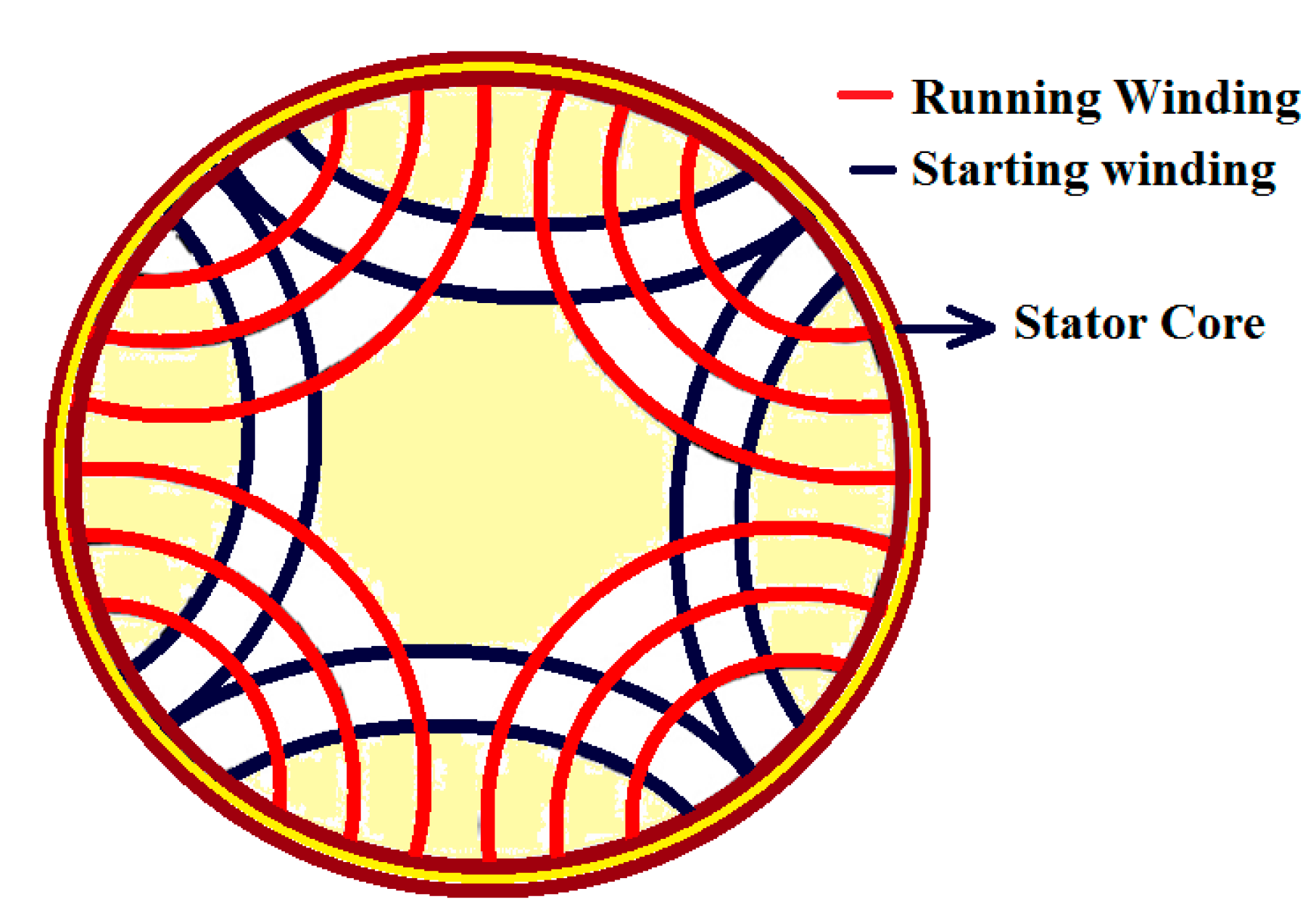
2.2. Working as Single-Phase Induction Motor
In operation of a single phase induction motor starting and running windings are placed in the same slot as the three-phase winding slots. The starting or auxiliary winding and running winding are separated electrically by 90° in space. An external capacitor is provided for starting the motor. The single-phase motor connection diagram is shown in
Figure 1.
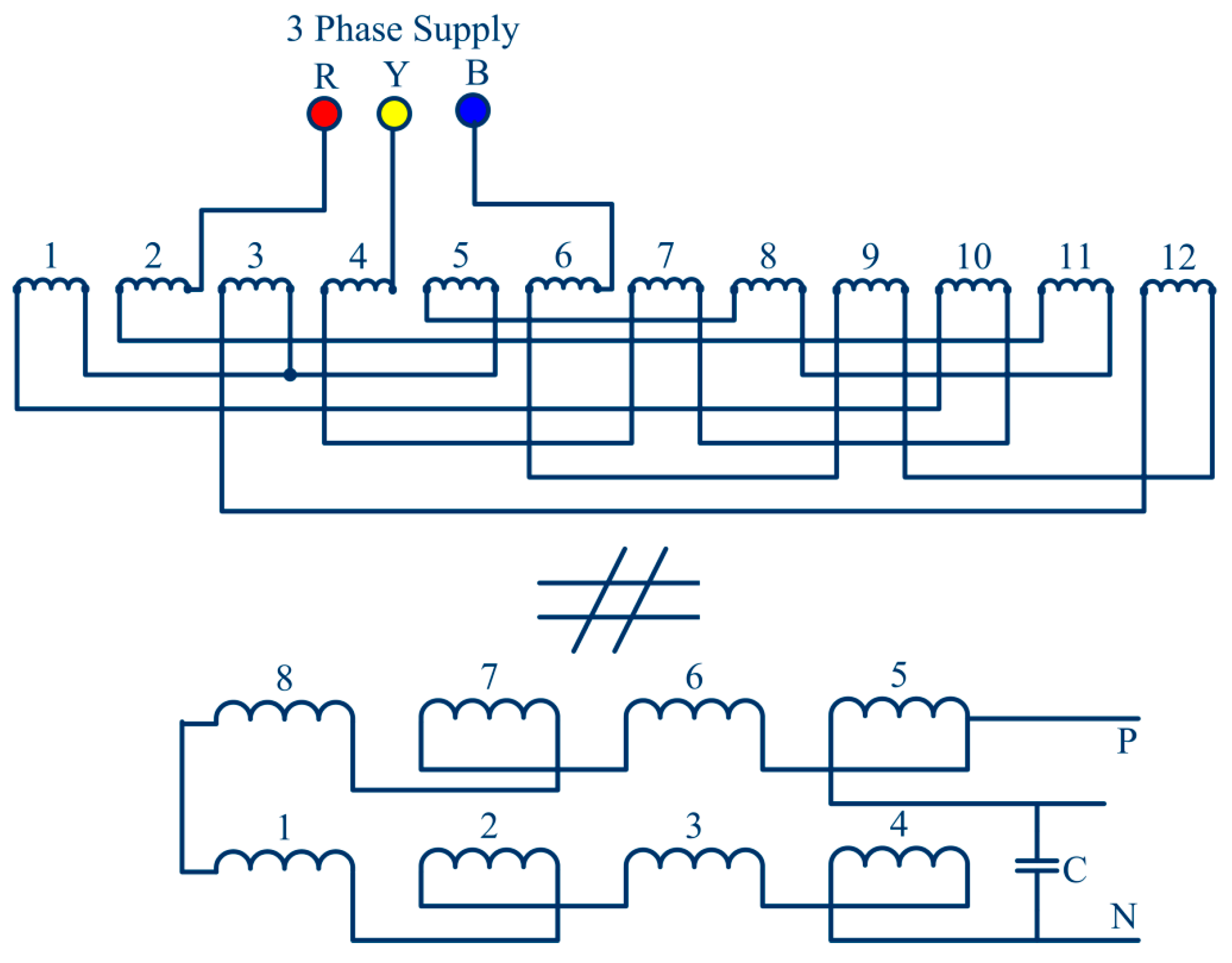
2.3. Working as a Welding Transformer
Figure 2 describes the working diagram of the machine configured to run as a welding transformer. In welding transformers high currents are produced at the secondary side. In the welding transformer operation, the running windings of the single-phase motor are taken into consideration to get a voltage step down. Four running windings are then connected in parallel to meet the high current requirements sufficient for welding.
2.4. Working as a Phase Converter
If there is only single phase supply then the motor cannot operate as a three-phase machine or if there is only three-phase supply then the motor cannot operate a sinlge-phase machine. Then phase conversion is possible from 1-phase to 3-phase and 3-phase to 1-phase and vice-versa. Phase converters are applied where it is difficult to erect a three-phase loading system because of arrangement requirements and cost. The proposed induction motor consists of three-phase as well as single-phase windings in its stator. When the machine is supplied at the stator EMF also gets induced in single-phase windings across which a single-phase voltage occurs.
Figure 3 shows an equivalent diagram of the proposed IM winding design operating as a phase converter.
3. Design of the Proposed Multifunctional Induction Machine Based on a New Winding Scheme
To design the proposed multifunctional induction machine, the original windings of the conventional induction motor (IM) are divided into three distinct windings with four groups on the basis of the number of turns. The first winding is with the same gauge wire and half of the original number of turns. Hence, this is a winding of a 3-phase induction motor and as the number of turns is half the motor has only half the capacity. The other windings are used for the purpose of welding and act as a tap of the welding transformer. As the welding application requires high current rating, a triple layer winding is used to improve the current rating. The same motor is used for a 1-phase induction motor. Hence, these windings are also used as starting and running windings of the 1-phase induction motor.
The winding factor initially assumed is 0.955, which is the value of the winding factor for infinitely distributed winding with full pitched coils. Flux per pole and stator winding per phase are calculated by Equations (1) and (2) respectively, where θm is flux per pole, Vs is stator voltage per phase, Bav is the average value of fundamental flux density, is pole pitch, d is the inner diameter of stator, l is length of the induction motor, P is number of poles, VS is stator voltage per phase, f is supply frequency in Hz, TS is the number of turns per phase in stator and KWS is stator winding factor.
The current density in the stator winding is usually between 3 to 5 A/mm
2. For a lower current value round conductors would be more convenient to use while for higher current bar or stripped conductor with 1 cm
2 in cross sectional area should be adopted [
22]. The area of each stator winding (A) is calculated by Equation (3) where,
IS is stator current per phase and
is the current density in the stator. The approximate area of each slot is equal to ratio of copper area per slot to space factor.
The space factor ordinarily varies from 0.25 to 0.4. High voltage machines have a lower space factor owing to the large thickness of insulation. After obtaining the area of the slot, the dimensions of the slot should be adjusted. The width of the slot should be within limits to maintain the required width of the teeth. The width of the slot should be so adjusted such that the mean flux density (Wb/m
2) in the teeth lies in between 1.3 to 1.7.
Table 1 shows the ratings and the parameters of the IM designed as a multifunctional motor:
3.1. Three-Phase Winding Design
With the help of measuring instruments the slot pitch is calculated and the type of winding is decided from it. It will be easy to do coil groups of both single and double layer windings. The film papers with the proper size are first inserted in order to protect the conductor insulation, which may be damaged by rubbing stator. Again the coils are also covered on the upper portion.
Then the free space will be added in order to do the single-phase connection. In this way the three- phase winding can be designed. For three-phase winding there are 17 turns per coil and hence for 36 slots, 12 slots per phase, hence 12 coils per phase and total number of 3-phase winding turns = 17 turns × 36 slots = 612 turns. For good conductivity super enameled wire is used (“super” is marketing name given by the enameled wire manufacturer). It is of class B type insulation. For designing the motor, there will be double layer winding with consideration of the stator winding parameters given in
Table 2.
Figure 4a,b depict the three-phase winding arrangement of the motor in slots and the actual placement of the three-phase windings on the stator, respectively. A three-phase 2.5 HP IM current is calculated by Equation (4).
3.2. Single-Phase Winding Design
The rated current and voltage for the single-phase motor is 10.15 A, 230 V while the power and frequency remain same. Here, design of the single-phase winding is very important as the same single-phase winding is used for welding purposes, so during the welding process the current carrying capability of the winding should withstand the current demands. At that time the machine should withstand high currents without any problems like over-heating, over-current/voltage or insulation damage. For this reason conductors having a current capacity double than the rated current are employed. The winding arrangement of the proposed motor is done with the placement of 90° electrical degree separation between the starting and running windings. Four coil groups of starting windings and four coil groups of running windings are designed. There are two starting and running windings placed electrically at 90° with the capacitor star arrangement in the single-phase induction motor. There are 17 turns per coil, meaning that the double layer turns per coil is equal to 34. Running winding having three layers is selected, so the total number of running winding turns is equal to 408 turns.
Figure 5 shows the actual placement of the single phase windings on the stator.
A single-phase 2.5HP IM current is calculated by Equation (5):
3.3. Welding Transformer Design
For this application the three-phase winding functions as the primary of the transformer and the running winding of the single-phase motor works as the secondary of the welding transformer. Hence, the welding transformer application is only related to running windings and it is also possible to use the starting winding for higher current rating welding applications. The transformation ratio of the welding transformer is given in Equation (6) where N1, N2 are the turns of the primary and secondary windings and I1, I2 are primary and secondary winding currents of the welding transformer:
From the above Equation (4), I2 can be calculated by using Equation (7) and is equal to the current in each winding of single phase which is 18.30 A, as three-phase winding turns (welding transformer primary winding turn) N1 is equal to 612 turns, single-phase winding turns (welding transformer secondary turn) N2 are equal to 102 turns and the rated three phase current I1 = 3.05 A. From this calculation the welding transformer current is 18.31 A per coil, hence by connecting these four coils in parallel this current is added and finally the welding transformer gets nearly 70 to 75 A current for welding. This current is able to provide a smooth output for welding with 2.5 mm welding rods.
3.4. Phase Converter Design
Phase converter calculations can be done with the same procedure as the welding transformer. Here the complete single-phase winding is considered in a circuit including auxiliary winding which states that the total number of single-phase windings is equal to the number of three-phase windings, i.e., primary turns is equal to secondary turns and the transformation ratio is 1. However, the input is three-phase line voltage of 400 Volts, so the output phase voltage, Vph = 400/1.7321 = 230 Volts are achieved as single-phase output. Hence single-phase supply can be obtained from a proposed design of the motor. The phase converter calculation is similar to transformer calculation because here the energy transformation is achieved by mutual induction; hence the transformation ratio (Equation (7)) and the EMF equation of the transformer are used to calculate voltages.
4. Hardware Assembly and Testing Results of the Proposed Induction Machine
An old scrap inductor motor (IM) was used to verify the proposed concept. In
Figure 6a the old IM is depicted and its windings are redesigned as shown in
Figure 6b.
In
Figure 6c the rotor of old machine which is a squirrel cage type is shown. In
Table 3 the specifications of the old IM are given.
Figure 7a depicts the hardware implementation of the stator winding of the proposed machine design.
Figure 7b depicts the complete stator winding arrangement which consists of both windings.
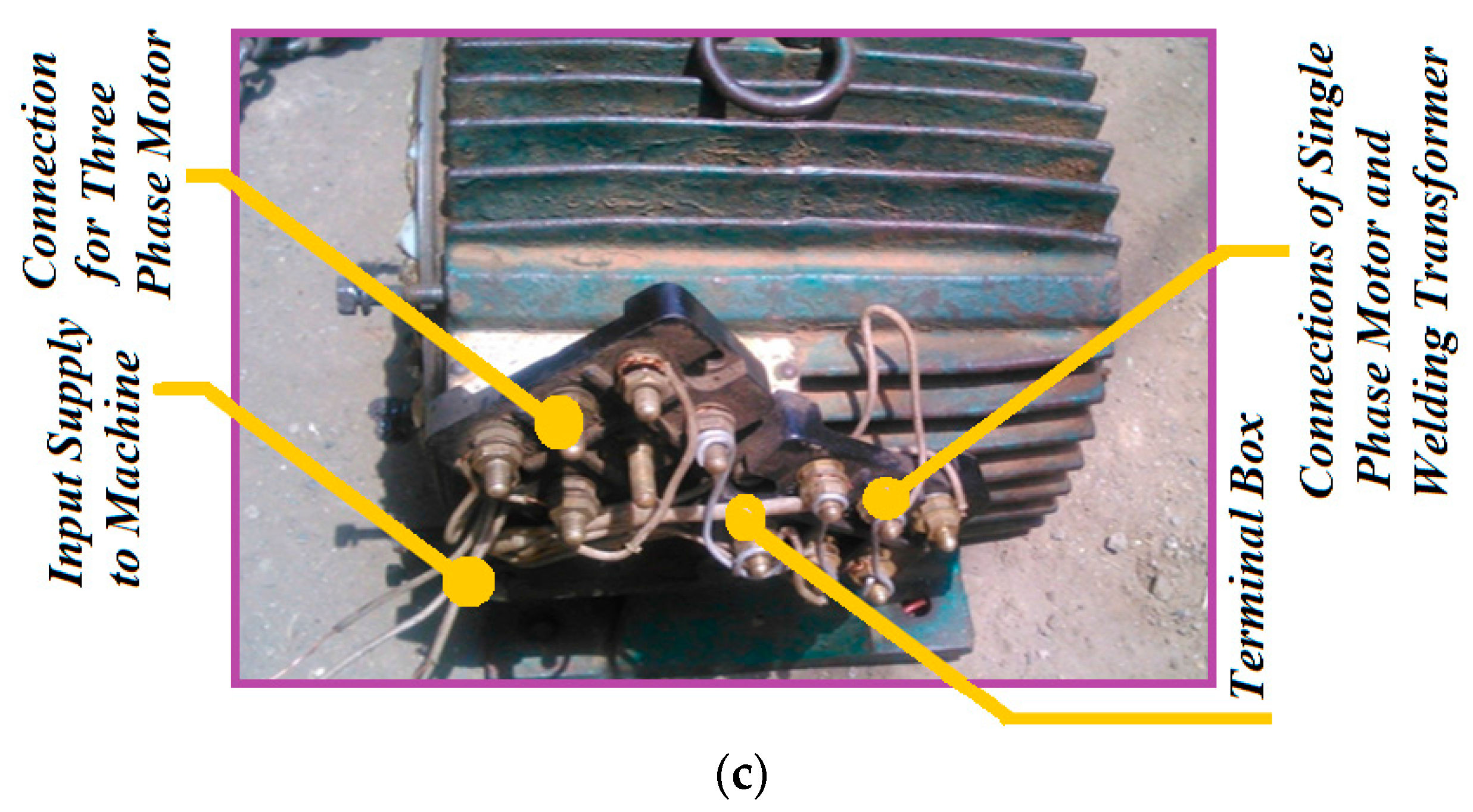
Figure 7c depicts the end terminals of the proposed designed machine. A conventional two wattmeter (W
1 and W
2) open circuit test (OCT) and blocked rotor test (BRT) are performed on the three-phase and single-phase induction motor to calculate its efficiency. The multiplying factor is calculated for three-phase and single-phase operation by using Equation (8).
Table 4 and
Table 5 describes the OCT and BRT results of the proposed IM as a three-phase induction motor and single-phase induction motor, respectively.
In
Table 4 and
Table 5,
VO is the line to line voltage,
IO is the stator phase current,
VBR is the stator line to line voltage in blocked rotor mode,
IBR is the stator phase current in a blocked rotor mode, W
1 and W
2 are the readings of two wattmeters used in the OCT and BRT test.
Table 6 shows the output voltage and current of the welding transformer which is sufficient to perform arc welding and
Table 7 shows the output voltages of the phase converter at an input of 230 V. In
Table 8 the welding transformer winding specifications are given.
For three phase operation:
Input power (Pin) = 1.7321 × 440 × 3.05 × 0.8 = 1860 W
Output power (Pout) = 1860 − losses (no load + block rotor) = 1860 − (360 + 160) = 1340
Hence, Efficiency (ή) = Pout/Pin × 100 = (1340/1860) × 100 = Efficiency (ή) = 72.64%
For Single phase operation:
Input power (Pin) = 220 × 10.5 × 0.8 = 1860 W
Output power (Pout) = 1860 − losses (no load + block rotor) = 1860 − (680 + 520) = 660 W
Hence, Efficiency (ή) = Pout/Pin × 100 = (660/1860) × 100
Efficiency (ή) = 35.48%
5. Merits and Applications of the Proposed Induction Machine
The following are the noticeable merits of the proposed induction machine:
The multifunctional motor is simple and robust in construction.
The motor is able to do at a time two operations, i.e., motoring and welding.
The motor requires less space.
Another advantage is that it has less weight compared to separate combinations of welding transformer and induction motor as well.
Hence, the cost required for two different machines is reduced, with high efficiency.
The cost is less.
The following are a few applications of the proposed induction machine.
The use of multipurpose motors is very convenient for use in mega workshops where both welding and motoring applications are required.
These types of motors are also useful in an electric traction systems where the space requirements is small.
Metal cutting workshops are another example where multifunctional motors would be useful.
It can also be used in heavy fabrication industry.
Multifunctional motors are very useful in the steel industry.
6. Conclusions
A new winding scheme is articulated to utilize a three-phase induction machine for multifunctional operation. The proposed motor provides an operative solution for agricultural as well as industrial purposes because of rugged construction and less maintenance needs. The proposed winding scheme is adapted to utilize a three-phase induction machine as a three-phase induction motor, single-phase induction machine, and welding transformer and phase converter. This new design does not need any kind of special arrangement and can be constructed with small modifications of any standard three-phase induction motor. The proposed concept is verified by designing a motor by modifying the windings of an old induction motor (IM) and the proposed motor is well tested to find its efficiencies and the experimental results are provided in the article to validate the design and construction.

 ,
, 


