Numerical Study on the Acoustic Characteristics of an Axial Fan under Rotating Stall Condition

School of Energy, Power and Mechanical Engineering, North China Electric Power University, Baoding 071003, China
*
Author to whom correspondence should be addressed.
Energies 2017, 10(12), 1945; https://doi.org/10.3390/en10121945
Submission received: 23 October 2017
/
Revised: 17 November 2017
/
Accepted: 20 November 2017
/
Published: 23 November 2017
(This article belongs to the Special Issue Engineering Fluid Dynamics 2018)
Abstract
:Axial fan is an important piece of equipment in the thermal power plant that provides enough air for combustion of coal. This paper focuses on the aerodynamic noise characteristics of an axial fan in the development from stall inception to stall cells. The aerodynamic noise characteristic of monitoring region in time and frequency domains was simulated employing the large-eddy simulation (LES), with the addition of throttle setting and the Ffowcs Williams-Hawkings (FW-H) noise model. The numerical results show that, under the design condition, the acoustic pressure presents regular periodicity along with the time. The noise energy is concentrated with high energy of the fundamental frequency and high order harmonics. During the stall inception stage, the acoustic pressure amplitude starts fluctuating and discrete frequencies are increased significantly in the low frequency; among them, there are three obvious discrete frequencies: 27.66 Hz, 46.10 Hz and 64.55 Hz. On the rotating stall condition, the fluctuation of the acoustic pressure level and amplitude are more serious than that mentioned above. During the whole evolution process, the acoustic pressure peak is difficult to keep stable all the time, and a sudden increase of the peak value at the 34.5th revolution corresponds to the relative velocity’s first sudden increase at the time when the valve coefficient is 0.780.
1. Introduction
Axial fan is an important piece equipment in the thermal power plant that provides enough air for combustion of coal. There are two unstable flow phenomena for axial flow fan: rotating stall and surge. If the flow rate decreases below the critical value, the inner flow-field of impeller will be deteriorated and then the rotating stall occurs, which will lead to a phenomenon of surge. The surge will cause the variation of flow rate in a big scope and generate the impact of airflow. Once surge frequency agrees with natural frequency of fan, it can cause a big vibration of the fan and connecting pipes, and then the blade fracture will appear. Thus, for the safe operation of an axial fan, it is necessary to find a method to predict and delay the occurrence of stall inception [1].
Rotating stall is caused by the collapse of the steady flow field within the fan. Therefore, finding the stall inception accurately and rapidly, and learning its mechanism are the keys to the active control of rotating stall during process from stabilization to collapse of the flow field [2,3,4]. Mcdougall et al. [5] considered that, when the rate of flow within impeller decreases, part of the blade passages’ flow will decrease and the rest will keep the large flow, which leads to the rotating stall. Through the three-dimensional numerical simulation about the transonic fan rotor considering the external disturbances. Niazi [6] found that the reflux appeared at the blade tip clearance firstly. The interplay of the reflux and shock wave leads to the rotating stall. Moore [7] and Greitzer [8] developed linear and nonlinear models of instability of the compression system, and obtained correlation between the compressor aerodynamic stability and the stall inception, which develops and spreads along the circumferential. Kosuge et al. [9] conducted the experiment of stall and surge phenomena on two different airfoil centrifugal impellers without diffuser under the small flow, and studied the influence of structure on stall. Yamada et al. [10] conducted a numerical analysis of the rotating stall inception on a multi-stage axial flow compressor for an actual gas turbine by large eddy simulation. The results showed that the first observed flow phenomenon in the stalling process is the hub corner separation when approaching the stall point. This hub corner separation expanded with time, and eventually leaded to the leading-edge separation on the hub side for the stator. Salunkhe and Pradeep [11] analyzed the stall inception mechanism in a single stage axial fan under undistorted and distorted inflow condition by the Morlet wavelet transform. Toge and Pradeep [12] attempted to study the stall inception mechanism of the low speed, contra rotating axial fan stage by wavelet transforming the unsteady pressure date from the casing wall sensor. The result clearly showed that stall inception occurs mainly through the long-length scale perturbations of both rotors. Li et al. [13] used the characteristic of vortex noise, the bar theory and nonlinear aerodynamics theory to analyze force acting on the blade in theoretical method. It analyzed the affecting factors of the vortex noise in the model qualitatively. There have been many studies on the induced mechanism of rotating stall in turbomachinery. However, it is worthy of further study on the new method to early detect stall for control.
The internal flow field of the fan is related to the aerodynamic noise. The noises of the fan mainly consist of aerodynamic noise, machinery noise and radiation noise [14]. Among them, aerodynamic noise occupies the main position, which includes the rotational noise and vortex noise. Liu et al. [15] obtained the spectrum characteristic of the double rotor by simulating different axial gaps, to determine the optimal range of the rotor spacing. Diaz [16] proposed a noise prediction method, and a single stage axial flow fan in the far field noise was predicted, and he proved the reliability of the method. Fukano and Jang [17] conducted contrast experiments in different flow coefficient under different tip clearance in a low-pressure axial flow fan. The results show that the tip leakage vortex mutual interference leads to the increase of fan noise. Wang et al. [18] used the technique of synchronous averaging with time-base stretching to decompose the original sound signal into various noise sources and analyze the noise characteristics of two identical small axial cooling fans in series with distorted inlet flow. It is found that the inlet flow distortion increases the total sound pressure level and rotational noise of the upstream fan, but has little effect on the rotation noise of the downstream fan. Feng et al. [19] predicted noise at different points by the point force model, and then used the hybrid method based on computational fluid dynamics (CFD) simulation and FW-H equation to predict the noise of the fan model. The results show that geometric asymmetry may significantly increase fan noise at some frequencies compared to symmetrical rotation. Mao et al. [20] studied the effect of the end- plate on the static and noise characteristics of the small axial fan by numerical simulation and experiment. He showed that the mechanism of noise reduction is due to the decrease of the vorticity of the blade surface caused by the end plate. At present, the research on the axial fan noise is mainly focused on steady operating conditions. When the unsteady phenomenon of rotating stall occurs, the flow field in axial fan will be significantly different with no stall conditions. Thus, the acoustic characteristic in the whole unsteady process from near stall to stall condition may be different.
This paper, through the large eddy simulation coupled with the throttle valve model, simulates the rotating stall of an axial fan and calculate the unsteady flow field. Then, to predict the noise of the fan, the FW-H equation based on Lighthill acoustic analogy theory is used. The time domain characteristic of acoustic pressure and acoustic pressure peak in the rotor blade domain are researched under four different conditions: the design condition, the near stall condition, the development of stall inception condition and the rotating stall condition. Finally, after obtaining the source data in time domain integration and then applying fast Fourier transform, the noise spectrums of the acoustic pressure level and amplitude at the rotor blade domain are investigated under the four conditions mentioned above.
2. Numerical Simulation
2.1. Subsection with Geometry
Figure 1 shows the single-stage variable pitch axial fan, which is taken as the research object in this paper. The facility consists of an inlet collector, a rotor, a stator and an outlet diffuser. The three-dimensional geometric model of the axial fan is established by ICEM CFD software (ANSYS 15.0, ANSYS Inc., Pittsburgh, PA, USA). The main parameters are shown in Table 1.
2.2. Figures, Tables and Schemes
ICEM CFD (The Integrated Computer Engineering and Manufacturing code for Computational Fluid Dynamics) software is used to generate the multi-block structure grids of the whole axial fan. Near the leading-edge and trailing-edge of each blade, the separation of boundary layer will form some separation vortexes. The grids of those parts are encrypted as the tip clearance grids to improve the precision of calculation. Figure 2 shows the grids around the leading-edge and trailing-edge. In addition, the sliding mesh model is applied at the interface between the rotor and the stator. Moreover, to ensure that the average wall distance y+ is less than 5, boundary layer grids are used on the surface of the blade. Figure 3 shows local grid of the impeller blade and the enlarged view around the impeller. Grid-independence verification was conducted to ensure a high accuracy of the simulation results [21].
2.3. Governing Equations
Governing equations include the fluid continuity equation, Navier-Stokes equations and turbulence model. Because the Mach number of the air flow is below 0.3, the density is regarded as constant. In steady calculation, SST turbulence model is selected as turbulence model. In unsteady simulation, to solve the unsteady phenomenon of rotating stall, the large eddy simulation (LES) is conducted. Equation of momentum is calculated by the two order upstream, and the physical time step of the unstable computation is 1.677 × 10⁻⁴ s, which means 240 time steps per revolution. To predict the noise of the fan, FW-H equation based on Lighthill acoustic analogy theory is adopted. Noise spectrum distribution from the axial fan is acquired after the source data have been obtained in time domain integration, and then fast Fourier transform processing are conducted.
2.4. Boundary Conditions
The inlet cross section of the collector and the outlet section of the diffuser are the inlet and outlet of the calculation domain. The inlet boundary condition of the fan is the pressure inlet, given the total inlet pressure; airflow direction angle is axial admission; and the outlet boundary condition is pressure outlet. For steady calculation, the MRF model is applied to the static and dynamic region coupling, and the throttle valve model is adopted to control the outlet pressure during the unsteady calculation. The function of the throttle model is as follows:
where k0 is a constant, k1 is throttle coefficient, ρ is density of the air, and U is velocity component of the z axial. Details of boundary conditions and throttle models are presented in [14].
3. Results and Discussion
3.1. Simulation Process of Rotating Stall
The variation of outlet static pressure is shown in Figure 4 when the valve coefficient k1 is 0.781 and 0.780, respectively. When the valve coefficient k1 is 0.781, the outlet pressure achieves a stable value quickly and has little change. However, when k1 is 0.780, outlet pressure tends to a stable value after five rotation cycles and then the outlet pressure declines sharply after the T = 34.5th revolution. Then, the values of outlet pressure fluctuate after about 10 rotation cycles. The throttle value k1 is 0.780, corresponding to the process of the occurrence and development of rotating stall.
To monitor the relative velocity inside the fan before and after rotating stall and acquire reliable evidence to analyze stall inception, three monitoring points, which are distributed at 50% of blade height and the circumferential interval is three impeller passages, are set up and marked as m1, m2 and m3, as shown in Figure 5.
Figure 6 shows the relative velocity of the three monitoring points in impeller when k1 is 0.780. The original relative velocity value of monitoring point m2 and m3 are moved up 60 units and 120 units, respectively, for comparison. As shown in Figure 6, a stall does not occur before the 34th revolution, while, after the 39.5th revolution, stall inception transforms to mature stall cell. In the growth process from the stall inception to the stall cell, peaks appear in the relative speeds of monitoring points. As m1, m2 and m3 are distributed evenly in the circumferential direction, there exists time difference when one blade passes through the three monitoring points. There are 0.375 revolutions between monitoring points m1 and m3, and they have the same waveform. Rotation speed of stall inception is obtained from Equation (2), and the rotation speed of stall inception is 0.67 times the rotating speed of the rotor:
where ws is the rotational speed of stall inception, and wr is the rotational speed of the rotor.
The streamline of relative velocity is analyzed for the section (Figure 7) where Z = 0 cm at four different conditions. The distribution of relative velocity streamline at Z = 0 section is shown in Figure 8 when the valve coefficient is 0.780. Figure 8a shows the formation of the first vortex on the 34.5th revolution and it occupies 1/3 passage at the location of V1. The velocity streamline of V1 is uneven, while the distribution in the other passages are uniform, indicating that stall inception occurs in the location V1 and does not spread along the circumferential direction.
When the second condition is reached, as show in Figure 8b, there are two locations, V1 and V2, where the velocity streamline is uneven. The interval between V1 and V2 is four passages on counterclockwise direction. The area of disturbance at V2 ranges from 90% blade height to blade tip, which means the appearance of the second vortex. This phenomenon corresponds to the obvious increase of relative velocity at 36.05th revolution, as shown in Figure 6.
Figure 8c shows the occurrence of the third vortex at the location V3, and there appear uneven distribution on four passages. At the same time, a corresponding peak also appears in the relative velocity at 37.6th revolution, as shown in Figure 6. After the process of two revolutions, there distribute four stall cells within the impeller and they are uniform on circumferentially direction, as shown in Figure 8d. The evolution from stall inception to the mature stall cell lasts seven revolutions.
3.2. The Time Domain Characteristic of Acoustic Pressure
Figure 9 shows the time domain characteristic of acoustic pressure at monitoring point A, shown in Figure 7, under the four different conditions mention above. The time domain characteristic of acoustic pressure under the design condition are illustrated in Figure 9a; the two revolutions in this figure are selected randomly. Figure 9a shows that the periodicity of acoustic pressure is regular and its fluctuation amplitude is basically equal. The uniform distribution of the 48 equal pulse peaks corresponds to the number of passing blades in two cycles. This phenomenon indicates that the internal flow field of the fan is stable, with fluid flowing into each channel uniformly. The incentive effect between ambient air and each leaf blade is the same, so the production of acoustic pressure is equal.
Figure 9b shows the time domain characteristic of acoustic pressure when the value coefficient k1 is 0.780; the two revolutions are selected randomly before the 34.5th revolution. It is the condition near stall stage. The acoustic pressure in the monitoring point A is almost regular, and the waveform of sound pressure shows little fluctuation during the two revolutions. Compared with Figure 9a, the acoustic pressure amplitude becomes large and has few fluctuations due to the decreasing of throttle coefficient leading to the decrease of fan flow rate.
As shown in Figure 9c, the stall inception condition is achieved; two revolutions are selected when stall inception occurs. The acoustic pressure amplitude shows obvious increase on the 34.5th revolution. Then, the two other acoustic pressure amplitudes increase obviously in the 34.6th and the 34.9th revolution, respectively. The acoustic pressure amplitude values of the three obvious increases have little difference. In addition, compared with Figure 9b, the fluctuation of acoustic pressure amplitude increases. This phenomenon indicates that, as the flow rate decreases, the uneven distribution of the fluid flow in the impeller leads to the damage of flow field, the acoustic pressure fluctuation becomes larger and the acoustic pressure amplitude increase sharply.
The time domain characteristic of acoustic pressure on the mature stall cell condition is shown in Figure 9d. As can be seen, the fluctuation of acoustic pressure amplitude becomes more serious compared to the three other conditions. The acoustic pressure waveform has a periodic fluctuation. However, the fluctuation cycle of acoustic pressure is not a specific value. This phenomenon shows that the stall cells within the impeller are not stable.
3.3. The Time Domain Analysis of the Acoustic Pressure Peak
The acoustic pressure peak pulsation at monitoring point A under three valve coefficients are shown in Figure 10. Figure 10a shows the acoustic pressure peak pulsation under design condition at monitoring point A. As can be seen from the graph, the acoustic pressure peak has a little fluctuation near the value −410 Pa and basically remains a stable value. Figure 9b shows the acoustic pressure peak pulsation when k1 is 0.780 and 0.660, respectively. We can see that, when the valve coefficient is 0.780, the fluctuation range of acoustic pressure peak during the first 30 rotation cycles is small and it is similar to the distribution under design condition (as shown in Figure 9a). However, the stable value of acoustic pressure peak is −360 Pa, owing to the decrease of flow rate. The peak of acoustic pressure is difficult to keep stable after a period of time. An obvious increase of the peak value appears at the 34.5th revolution, at the moment stall inception occurs and then enters the rotating stall stage, as shown in the red circle marked RS, and the variation of peak value is 341 Pa. Afterwards, the fluctuation of acoustic pressure peak becomes more serious, and the maximum variation of peak value is 533 Pa. When the valve coefficient k1 is 0.660, at the beginning of the rotation cycles, the fluctuation of peak value is also in a small range, and the stable value is about −330 Pa. however, after fewer than two rotation cycles, the value of peak increases obviously and the variation of peak value is 169 Pa, as shown in the red circle marked RS. Compared with when the valve coefficient k1 is 0.780, the oscillation of acoustic pressure peak becomes larger, and the maximum variation of peak value is 873 Pa. To sum up, when the valve coefficient is 0.66, the peak of acoustic pressure presents an obvious increase after fewer than two revolutions. However, the appearance of this phenomenon needs quite a long time for the value of peak k1 to be 0.780. The peak of acoustic pressure presents little fluctuation and remains at a certain value under design condition.
3.4. Spectrum Analysis of the Noise
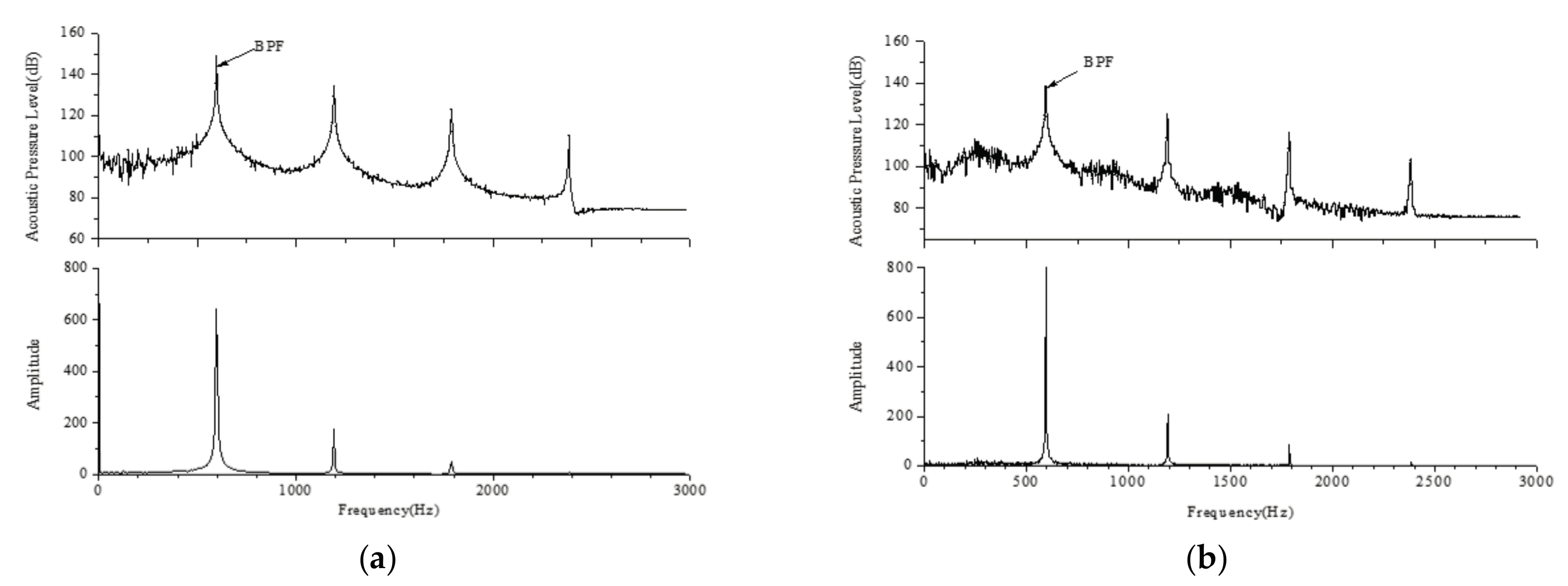
Fast Fourier transform (FFT) is used on the acoustic pressure distribution in time domain to obtain the noise spectrum of monitoring points (as shown in Figure 11). Then, the noise spectrum of different monitoring points is analyzed to obtain the distribution characteristics of noise in each frequency band. The noise spectrums of the acoustic pressure level and amplitude under the design condition are shown in Figure 11a. The blade passing frequency (BPF) of axial flow fan is f = 1490 × 24/60 = 596 Hz. As can be seen from the graph, the location of the blade passing frequency (BPF) and fundamental frequency is consistent. The harmonic distribution is consistent in the simulation and the theory. When the frequency is more than 2500 Hz, the change of the acoustic pressure level is very small, and the acoustic pressure level tends to be stable. This phenomenon shows that the fan aerodynamic noise has discrete and broadband characteristics at the same time.
When k is 0.78, the noise spectrum of the acoustic pressure level and amplitude is as shown in Figure 11b, and, in this period, the fan is at near stall condition. The acoustic pressure level presents a W shape in the low frequency and has a maximum value at f = 248.8 Hz. As can be seen from the graph, near the maximum value, the acoustic pressure level gradually decreases at both sides. Apart from frequency multiplication with the increase of frequency, the acoustic pressure level presents fluctuations, but the range of fluctuations in small, as displayed in the frequency domain of amplitude, and the very small amplitude tends to zero. Compared with Figure 11a, the fluctuation of acoustic pressure level enhances, as the decreasing of the flow rate increases the internal disturbance of axial flow fan.
The noise spectrum of the acoustic pressure level and amplitude, when stall inception occurs, is shown in Figure 11c. The discrete frequency increases significantly in the low frequency, as shown in Figure 11c, and there are three obvious discrete frequency. Figure 11c is partially enlarged, showing that the peaks of amplitude occurred at 27.66 Hz, 46.10 Hz and 64.55 Hz. Combined with Figure 7, during the evolution process of the rotation stall, the stall cells increase gradually, so these three frequencies are superposition results between frequency of stall inception and rotating stall. Compared with Figure 11b, the fluctuation of amplitude increases in the low frequency. This is because the fan has difficulty maintaining stability after a period, enters the rotating stall, and the damage of fan inner flow field leads to the enhancement of fan noise.
As shown in Figure 11d, mature stall cell come into being. The oscillation of the acoustic pressure level and amplitude are serious. Otherwise, the fluctuations of acoustic pressure level are enhanced with the increase of frequency in the high frequency. The deterioration of the internal flow field is the reason for the further enhancement of noise.
Figure 11 shows different characteristics of noise frequency spectrum at the four conditions mentioned above. However, the acoustic pressure level of each condition reduces with the increase of frequency. Using the noise intensity to measure, the strongest is fundamental frequency and the high order harmonic gradually weakened with the increase of frequency. The spectrum characteristics of noise is generally divided into three frequency bands: low-frequency noise is low than 500 Hz, and from 500 Hz to 1000 Hz is the mid-frequency noise, and high-frequency noise is high than 1000 Hz. The fluctuation of acoustic pressure level and amplitude are serious when the frequency is low than 500 Hz in each condition. The blade passing frequency is in the mid-frequency, so the aerodynamic noise of the axial fan is mainly low-frequency noise and mid-frequency noise. The rotation noise with discrete peak features are main noise in this frequency band. The peak value of low-frequency noise is the result of the periodic vortex shedding.
The physiological characteristics of human are sensitive to high-frequency noise but insensitive to low-frequency noise. Several kinds of filters are designed based on the loudness curve, and A-weighted acoustic pressure level is one of them. A-weighted (A-weighted is a standard developed by the American National Standards Institute in 1936, which describes the sensitivity of human ears to sound changes in different frequency bands.) acoustic pressure level is closest to the sensory characteristics of voice to the human ear. Thus, the A-weighted acoustic pressure level, combined with the 1/3 octave spectrum under the four conditions mentioned above, is used to observe the changes of the fan noise spectrum. The A-Weighted 1/3 octave spectrum of the four conditions as shown in Figure 12. The aerodynamic noise of axial flow fan mainly contains the discrete noise, and is mixed with the wide-band noise, the main component of the discrete noise are fundamental frequency and high order harmonics. Compared with the design condition, the fluctuation of acoustic pressure level is more intense in the low frequency after the occurrence of stall inception.
4. Conclusions
In this paper, the unsteady phenomenon of rotation stall in an axial fan is numerically studied through large eddy simulation with throttle valve model and FW-H noise model. In the case of axial fan rotating stall, the aerodynamic noise performance was analyzed. The main results can be listed as follows.
- (1)
- Flow fields are analyzed in detail in the evolution process of rotating stall. The relative velocity first increases rapidly at the 34.5th rotation revolution, and the relative velocity of streamline forms a vortex at the location V1. In the whole evolution process, one stall cell gradually developed into four stall cells that last for seven revolutions.
- (2)
- The time domain characteristics of acoustic pressure during the production and growth of rotation stall inception, at monitoring point A, are analyzed. Under the design condition, the acoustic pressure presents regular periodicity. During the growth procedure from the rotation stall inception to the stall cell, the acoustic pressure amplitude presents fluctuation, and the acoustic pressure peak has an obvious increase at the 34.5th revolution, which corresponds to the increase of relative velocity at this time. On the rotating stall condition, the fluctuation of acoustic pressure amplitude becomes more serious than the other conditions.
- (3)
- The noise spectrum of the acoustic pressure level and amplitude is also analyzed in this paper. The noise energy is concentrated on the fundamental frequency with high energy and high order harmonics under design condition. When stall inception occurs, discrete frequency increased significantly in the low frequency, which has three obvious discrete frequencies: 27.66 Hz, 46.10 Hz and 64.55 Hz. The frequency domain of A-weighted sound pressure level provides further evidence: the fluctuation of acoustic pressure level is more intense in the low frequency after the occurrence of stall inception, compared with the design conditions.
Acknowledgments
This research was supported by National Natural Science Foundation of China (Grant No. 11602085), and Natural Science Foundation of Hebei Province, China (Grant No. E2016502098).
Author Contributions
Lei Zhang and Chuang Yan conceived and analyzed the data; Lei Zhang wrote the paper; Ruiyang He and Qian Zhang provided advice for this method and revised this paper; and Kang Li contributed simulation tools. All authors have read and approved the final manuscript.
Conflicts of Interest
The authors declare no conflict of interest.
References
- Peng, C. Numerical Predictions of Rotating Stall in an Axial Multi-Stage-Compressor. In ASME 2011 Turbo Expo, Proceedings of the Turbine Technical Conference and Exposition, Vancouver, BC, Canada, 6–10 June 2011; Volume 6: Structures and Dynamics, Parts A and B; American Society of Mechanical Engineers: New York, NY, USA, 2011. [Google Scholar]
- Lei, Z.; Rui, W.; Wei, Y.; Wang, S. Simulation of air jets for controlling stall in a centrifugal fan. J. Mech. Eng. Sci. 2015, 229, 2045–2055. [Google Scholar] [CrossRef]
- Ohta, Y.; Fujita, Y.; Morita, D. Unsteady Behavior of Surge and Rotating Stall in an Axial Flow Compressor. J. Therm. Sci. 2012, 21, 302–310. [Google Scholar] [CrossRef]
- Chen, J.P.; Hathaway, M.D.; Herrick, G.P. Prestall Behavior of a Transonic Axial Compressor Stage via Time-Accurate Numerical Simulation. J. Turbomach. 2007, 130, 353–368. [Google Scholar]
- Mcdougall, N.M.; Cumpsty, N.A.; Hynes, T.P. Stall Inception in Axial Compressors. J. Turbomach. 1988, 112, 116–123. [Google Scholar] [CrossRef]
- Niazi, S.; Stein, A.; Sankar, L. Numerical studies of stall and surge alleviation in a high-speed transonic fan rotor. In Proceedings of the 38th Aerospace Sciences Meeting and Exhibit, Reno, Nevada, 10–13 January 2000. [Google Scholar]
- Moore, F.K. A Theory of Post-Stall Transients in Axial Compression Systems: Part I—Development of Equations. J. Eng. Gas Turbines Power 1985, 108, 68–76. [Google Scholar] [CrossRef]
- Greitzer, E.M.; Moore, F.K. A Theory of Post-Stall Transients in Axial Compression Systems: Part II—Application. J. Eng. Gas Turbines Power 1986, 108, 231–239. [Google Scholar] [CrossRef]
- Kosuge, H.; Ito, T.; Nakanishi, K. A Consideration Concerning Stall and Surge Limitations within Centrifugal Compressors. J. Eng. Power 1982, 104, 782–787. [Google Scholar] [CrossRef]
- Yamada, K.; Furukawa, M.; Tamura, Y.; Saito, S.; Matsuoka, A.; Nakayama, K. Large-Scale DES Analysis of Stall Inception Process in a Multi-Stage Axial Flow Compressor. In ASME Turbo Expo 2016, Proceedings of the Turbomachinery Technical Conference and Exposition, Seoul, Korea, 13–17 June 2016; American Society of Mechanical Engineers: New York, NY, USA, 2016; p. V02DT44A021. [Google Scholar]
- Salunkhe, P.B.; Pradeep, A.M. Stall Inception Mechanism in an Axial Flow Fan under Clean and Distorted Inflows. J. Fluids Eng. 2010, 132, 121102. [Google Scholar] [CrossRef]
- Toge, T.D.; Pradeep, A.M. Experimental Investigation of Stall Inception Mechanisms of Low Speed Contra Rotating Axial Flow Fan Stage. Int. J. Rotating Mach. 2015, 3, 1–14. [Google Scholar] [CrossRef]
- Li, L.; Huang, Q.; Qiao, Y. Research on model of the vortex noise of axial fan blade and its characteristics. China Mech. Eng. 2006, 17, 1056–1059. [Google Scholar]
- Zhang, L.; Wang, R.; Wang, S. Simulation of Broadband Noise Sources of an Axial Fan under Rotating Stall Conditions. Adv. Mech. Eng. 2014, 1–11. [Google Scholar] [CrossRef]
- Liu, P.; Jin, Y.; Wang, Y. Effects of rotor structure on performance of small size axial flow fans. J. Therm. Sci. 2011, 20, 205–210. [Google Scholar] [CrossRef]
- Diaz, A.K.M.; Fernandez, O.J.M.; Marigorta, E.B.; Morros, C.S. Numerical prediction of tonal noise generation in an inlet vaned low-speed axial fan using a hybrid aeroacoustic approach. J. Mech. Eng. Sci. 2009, 223, 2081–2098. [Google Scholar] [CrossRef]
- Fukano, T.; Jang, C.M. Tip clearance noise of axial flow fans operating at design and off-design condition. J. Sound Vib. 2004, 275, 1027–1050. [Google Scholar] [CrossRef]
- Wang, C.; Zhang, W.; Huang, L. Noise Source Analysis and Control for Two Axial-Flow Cooling Fans in Series. In Fluid-Structure-Sound Interactions and Control; Springer: Berlin/Heidelberg, Germany, 2016. [Google Scholar]
- Feng, T.; Wang, J.; Liu, B.; Li, N.; Wu, X. Computational simulation of rotating noise of fan. In Proceedings of the 2011 IEEE 3rd International Conference on Communication Software and Networks, Xi’an, China, 27–29 May 2011; pp. 728–731. [Google Scholar]
- Mao, H.; Wang, Y.; Lin, P.; Jin, Y.; Setoguchi, T.; Kim, H.D. Influence of Tip End-plate on Noise of Small Axial Fan. J. Therm. Sci. 2017, 26, 30–37. [Google Scholar] [CrossRef]
- Zhang, L.; Lang, J.H.; Liang, S.F.; Wang, S.L. Dynamic characteristic study on variable pitch axial fan impeller of the power plant. Proc. CSEE 2014, 34, 4118–4128. [Google Scholar]
Figure 1.
Geometrical model of the axial fan.
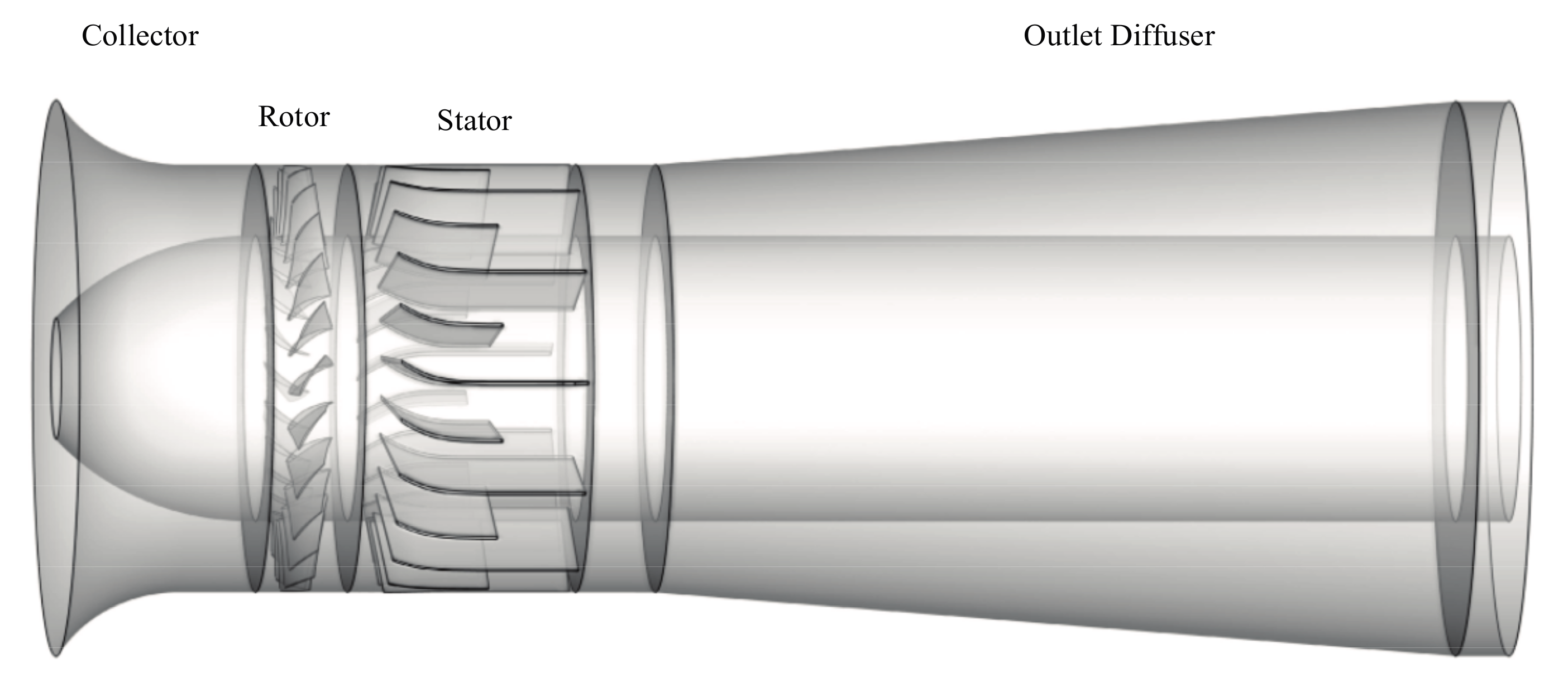
Figure 2.
Computational grid around main blade edge.

Figure 3.
Local grid of the impeller blade and enlarged view around the impeller.
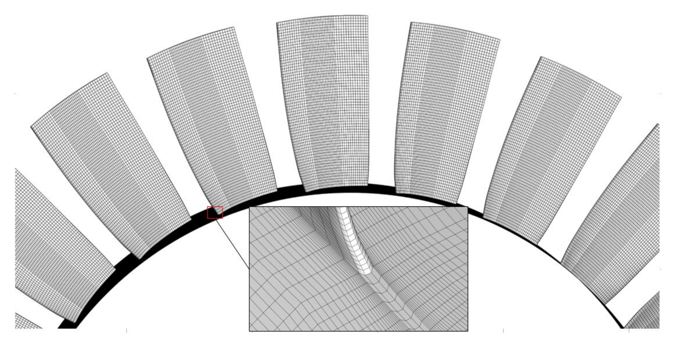
Figure 4.
The history of outlet pressure on two valve coefficients.
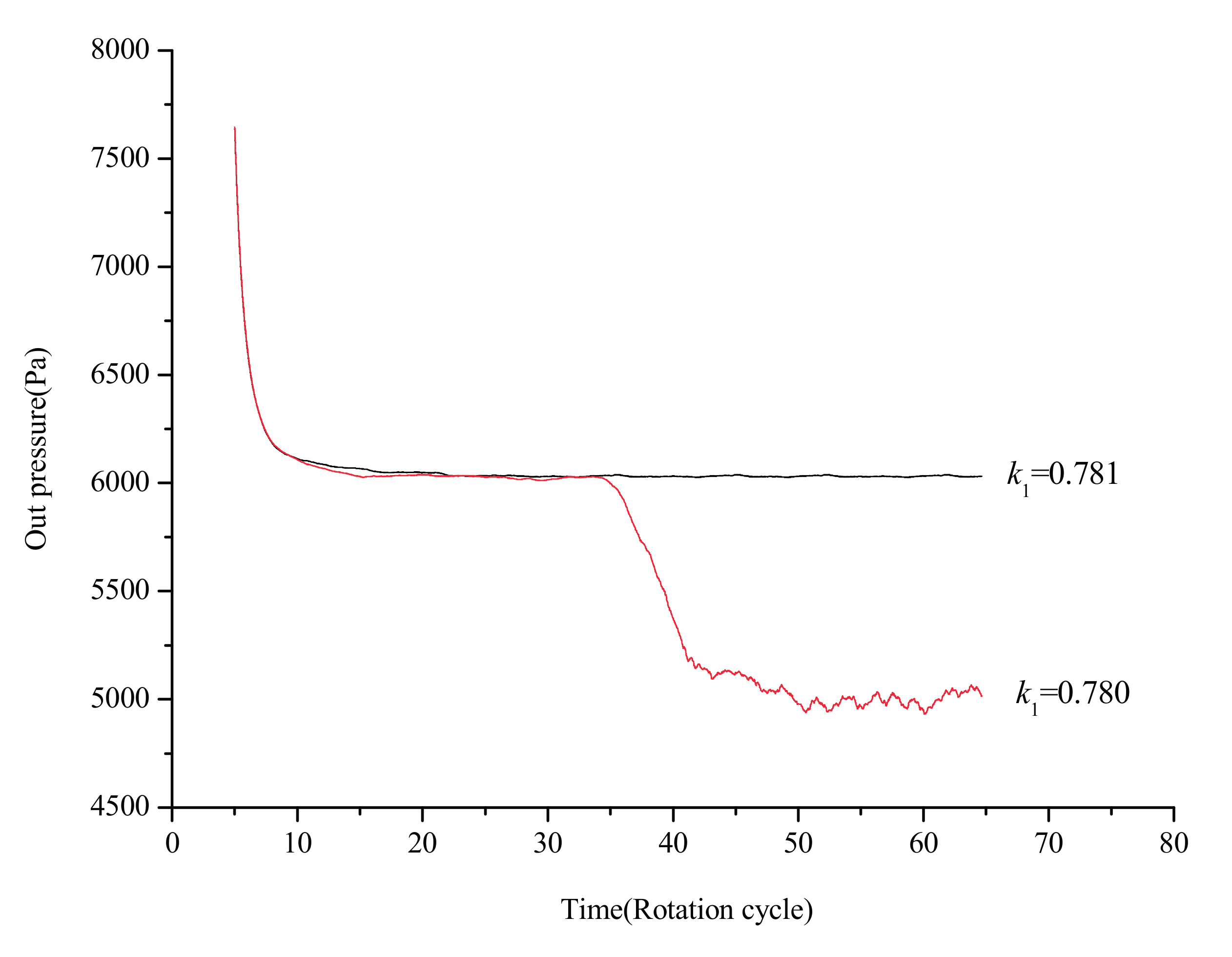
Figure 5.
The distribution of monitoring points.
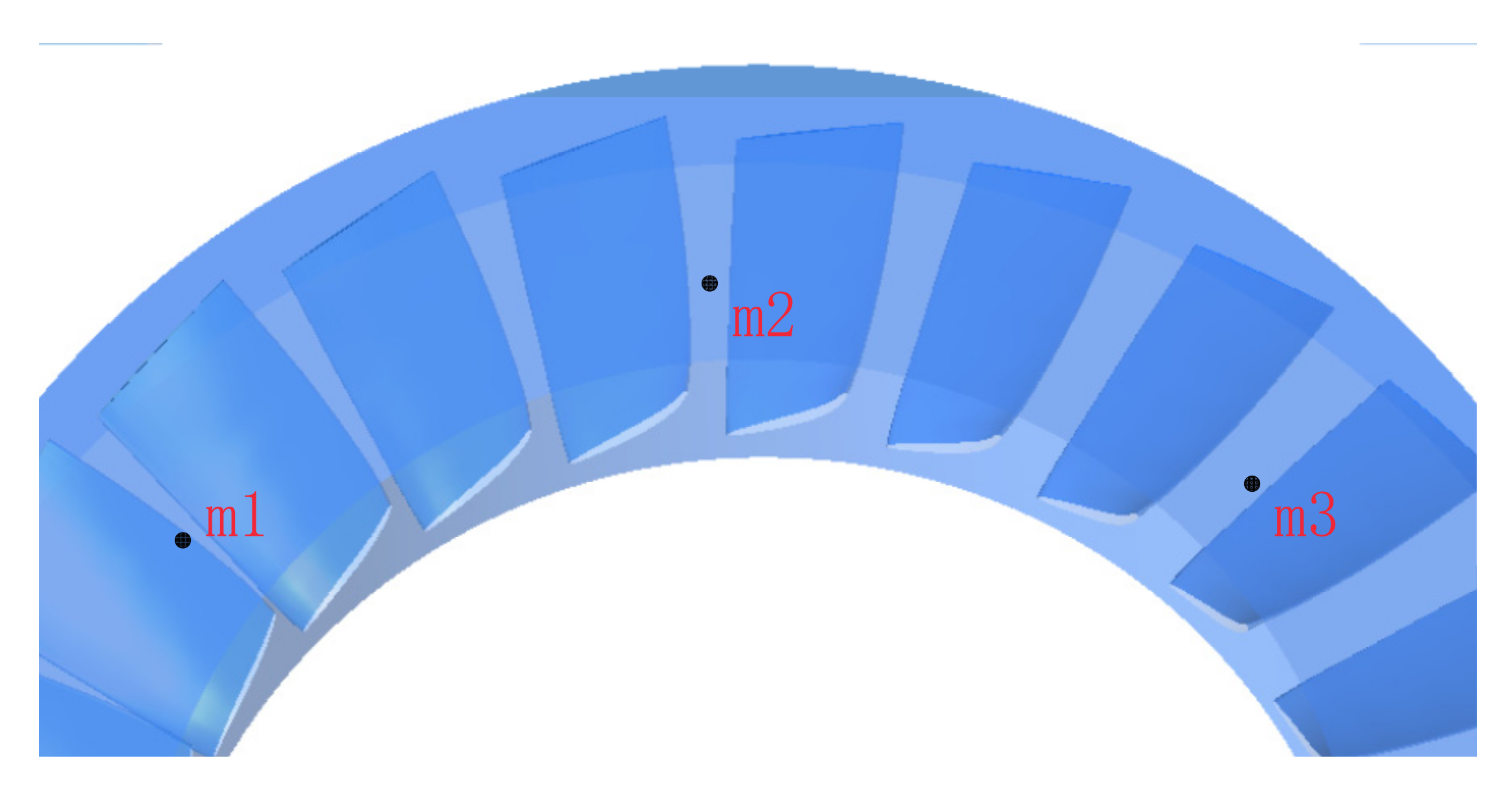
Figure 6.
Relative velocities of the monitoring points.

Figure 7.
The location of Z = 0 cm section and monitoring point A.
Figure 8.
The distribution of relative velocity streamline at Z=0 Section: (a) T = 34.5th; (b) T = 36th; (c) T = 37.5th; and (d) T = 39.5th.
Figure 8.
The distribution of relative velocity streamline at Z=0 Section: (a) T = 34.5th; (b) T = 36th; (c) T = 37.5th; and (d) T = 39.5th.
Figure 9.
The time domain characteristic of acoustic pressure at monitoring points A: (a) the design condition; (b) near the stall inception condition; (c) stall inception condition; and (d) the mature stall cell condition.
Figure 9.
The time domain characteristic of acoustic pressure at monitoring points A: (a) the design condition; (b) near the stall inception condition; (c) stall inception condition; and (d) the mature stall cell condition.
Figure 10.
Acoustic pressure peak in time domain under three conditions: (a) acoustic pressure peak under design condition; and (b) acoustic pressure peak for when k is 0.780 and 0.660.
Figure 10.
Acoustic pressure peak in time domain under three conditions: (a) acoustic pressure peak under design condition; and (b) acoustic pressure peak for when k is 0.780 and 0.660.

Figure 11.
Noise spectrum of the acoustic pressure level and amplitude at four conditions: (a) the design condition; (b) near the stall inception condition; (c) the development of stall inception condition; and (d) deep rotating stall condition.
Figure 11.
Noise spectrum of the acoustic pressure level and amplitude at four conditions: (a) the design condition; (b) near the stall inception condition; (c) the development of stall inception condition; and (d) deep rotating stall condition.

Figure 12.
A-weighted 1/3 octave spectrum of the four conditions.

Table 1.
Parameters of the axial fan.
| Parameter | Value |
|---|---|
| Rated speed n (r/min) | 1490 |
| Number of moving blade Nr | 24 |
| Number of stationary blade Ns | 23 |
| Inlet diameter D1 (m) | 2.312 |
| Outlet diameter D2 (m) | 2.305 |
| Rotor diameter D (m) | 1.778 |
| Hub ratio | 0.668 |
© 2017 by the authors. Licensee MDPI, Basel, Switzerland. This article is an open access article distributed under the terms and conditions of the Creative Commons Attribution (CC BY) license (http://creativecommons.org/licenses/by/4.0/).
Share and Cite
MDPI and ACS Style
Zhang, L.; Yan, C.; He, R.; Li, K.; Zhang, Q. Numerical Study on the Acoustic Characteristics of an Axial Fan under Rotating Stall Condition. Energies 2017, 10, 1945. https://doi.org/10.3390/en10121945
AMA Style
Zhang L, Yan C, He R, Li K, Zhang Q. Numerical Study on the Acoustic Characteristics of an Axial Fan under Rotating Stall Condition. Energies. 2017; 10(12):1945. https://doi.org/10.3390/en10121945
Chicago/Turabian StyleZhang, Lei, Chuang Yan, Ruiyang He, Kang Li, and Qian Zhang. 2017. "Numerical Study on the Acoustic Characteristics of an Axial Fan under Rotating Stall Condition" Energies 10, no. 12: 1945. https://doi.org/10.3390/en10121945
Note that from the first issue of 2016, this journal uses article numbers instead of page numbers. See further details here.