Dynamic Equivalent Modeling of a Grid-Tied Microgrid Based on Characteristic Model and Measurement Data
by
 ,
,
Changchun Cai
1,2,*, 
Haolin Liu
1,2,
Weili Dai
1,2,
Zhixiang Deng
1,2,
Jianyong Zhang
1 and
Lihua Deng
1,2 1
Jiangsu Key Laboratory of Power Transmission & Distribution Equipment Technology, Hohai University, Changzhou 213022, Jiangsu, China
2
College of IOT Engineering, Hohai University, Changzhou 213022, Jiangsu, China
*
Author to whom correspondence should be addressed.
Energies 2017, 10(12), 1951; https://doi.org/10.3390/en10121951
Submission received: 17 October 2017
/
Revised: 11 November 2017
/
Accepted: 20 November 2017
/
Published: 24 November 2017
(This article belongs to the Special Issue Sustainable and Renewable Energy Systems)
Abstract
:Microgrids can significantly improve the utilization of distributed generation (DG) and the reliability of the power supply. However, in the grid-tied operational mode, the interaction between the microgrid and the distribution network cannot be ignored. The paper proposes an equivalent modeling method for the microgrid under grid-tied mode based on a characteristic model. It can simplify the microgrid model in the numerical simulation of the distribution network. The proposed equivalent model can present the dynamic response of a microgrid but not miss any of its primary characteristics. The characteristic model is represented by a low-order time-varying differential equation with the same characteristics of the original microgrid system. During the modeling process, the voltage and the power exchanged between the microgrid and distribution network are collected as the training data for the identification of model parameters. A recursive damped least squares algorithm (RDLS) is used for the parameter identification. A microgrid system containing different DGs is built to test the proposed modeling method in DIgSILENT, and the results show that the proposed dynamic equivalent modeling method is effective and the characteristic model can present the dynamic behaviors of the detailed model of a microgrid.
1. Introduction
Traditional power systems have great economy and reliability challenges as more and more electrical energy needs to be transmitted from central energy generation sources to meet the increasing energy demands of diverse load centers Renewable distributed generation (DG) is a good alternative, with demonstrated cleanliness, economic and renewable features [1,2]. DG technology has been available for decades, however, DGs have not been connected on a large scale to power systems due to their intermittent and fluctuating nature. The impact of hybrid renewable energy sources on the power system is the key barrier for the connection of DGs [3]. Numerous issues, including bidirectional power flow [4], voltage imbalance [5], protective relaying [6], and power quality [7] need to be studied fully before the large-scale connection of DGs. In order to address these problems, microgrids were proposed and developed for the flexible connection of DGs and they represent a potential development trend for the power system of the future.
Microgrids have received considerable attention in recent years because of their capability to ease the problems of connected DGs. Typically, a microgrid operates at grid-tied mode, and it can be seen as a backup generation source for the distribution network [8,9,10]. However, the connection of microgrid clusters also brings new challenges for the power system. The interaction between the distribution network and microgrids should be considered in the simulation analysis and planning of distribution networks [11]. In power system stability studies, a suitable dynamic model of microgrids is needed. Microgrids are constituted by different components with different operational characteristics, it is difficult and time consuming to use a detailed model of microgrids in dynamic simulation analyses of distribution networks [12,13,14]. Therefore, it is necessary to study the reduced order equivalent modeling of the microgrid components and microgrid itself to simplify the model complexity and decrease the computational effort. In the grid-tied mode, a microgrid can be represented by an equivalent component with the same dynamic behavior asthe original system.
The dynamic equivalent method has been wildly used in power system dynamic equivalent modeling. It sets apart the study area out of the external area which can be represented by dynamic equivalent components through equivalent aggregation [15]. The common dynamic equivalent modeling methods for microgrids can be divided into two types: mechanism methods and non-mechanism methods. Mechanism methods are based on a detailed model and the dynamic characteristics of the original components [16]. In the equivalent modeling of microgrids, the aggregation of DGs is the main process, whereby the microgrid components are aggregated and the microgrid network is simplified for the simulation of microgrids connected to a distribution network [17]. However, the parameters of the equivalent model are too difficult to identify if the components and the detailed microgrid model are complex. Normally, a microgrid is an inverter-dominated small power system and the generalized homology equivalence theory for the equivalent modeling is proposed in [18], based on the dynamic of the inverter.
Non-mechanism methods include grey-box or black-box approaches which can overcome the lack of complete parameters and information about the layout of the DGs and network. In [19] an equivalent model of a microgrid is studied for the dynamic analysis based on an optimization method. In [20] a grey-box and hybrid dynamic equivalent model is proposed for transient power system analysis, and the measurement data of point of common couple (PCC) are collected for the parameter identification. A dynamic equivalent model of an Active Distribution Network based on a grey-box approach is proposed in [21], where the equivalent model comprises a generator and a composite load. An artificial neural network (ANN) method has been used for training the dynamic behaviors of Active Distribution Networks, giving an equivalent model of the system based on the measurement data [22]. In [23,24], the black-box model based on Prony analysis and the equivalent model composed of different Prony items, and the change of the topology of microgrid is presented by the introducing or subtracting the corresponding Prony items, and the parameters of the models are identified from the measurement data. Multi-agent-oriented methodologies for modeling the real-time operation of microgrids are discussed in [25], whereby each agent has its own function and represents a different component in the microgrid. Furthermore, the interactions between agents are considered in [26], and the dialogs among agents are included too.
Based on the former discussion, conventional methods for the dynamic equivalent modeling of power systems are based on knowing the parameters of the components. However, most times it is difficult to get enough parameter and topology information of real power systems. Hence, an equivalent model of a microgrid in grid-tied mode is necessary for the simulation of power systems. Characteristic modeling is a simplified modeling theory and method used in the engineering area, which was first proposed in the 1990s [27,28]. The characteristic modeling method considers both the dynamic characteristics and control performance requirements of the original dynamic system, rather than capturing the system dynamics as precisely as possible. It uses a reduced-order time-varying differential equation to describe the dynamics of the original system. The parameters and order of the characteristic model that need to be estimated can be reduced significantly for a complex system [29]. The slowly time-varying differential equation of the characteristic model represents the variation of the original system with the time-varying parameters. A microgrid is a time-varying system since the operational conditions of DGs are changing all the time, so the parameters of the equivalent model are time-varying too, therefore, we will attempt to use a characteristic model to represent the dynamic behaviors of the complex microgrid system.
In this paper, we adopt a characteristic model to handle the equivalent modeling of a microgrid in grid-tied mode based on measurement data. The dynamic behavior of the microgrid is represented by the characteristic model which is a second-order differential equation with time-varying parameters. During the process of modeling, voltage and exchange power of microgrid and distribution network in PCC are collected as the input and output training data of the equivalent model. A recursive damped least squares algorithm (RDLS) is used for the parameter identification, that tries to find the suitable parameters to match the dynamics of the original system. A series of microgrid operational scenarios are defined to verify the accuracy of our characteristic model.
The rest of this paper is organized as follows: in Section 2, we describe the model of different DGs and microgrids. In Section 3, the characteristic model and its application in a microgrid is presented. We also describe the modeling process of the characteristic model in the equivalent modeling of a microgrid. Simulation and results analysis are presented in Section 4 to illustrate the effectiveness of the proposed method. Section 5 presents our conclusions.
2. Distributed Generation and Microgrid Model
2.1. Wind Power Model
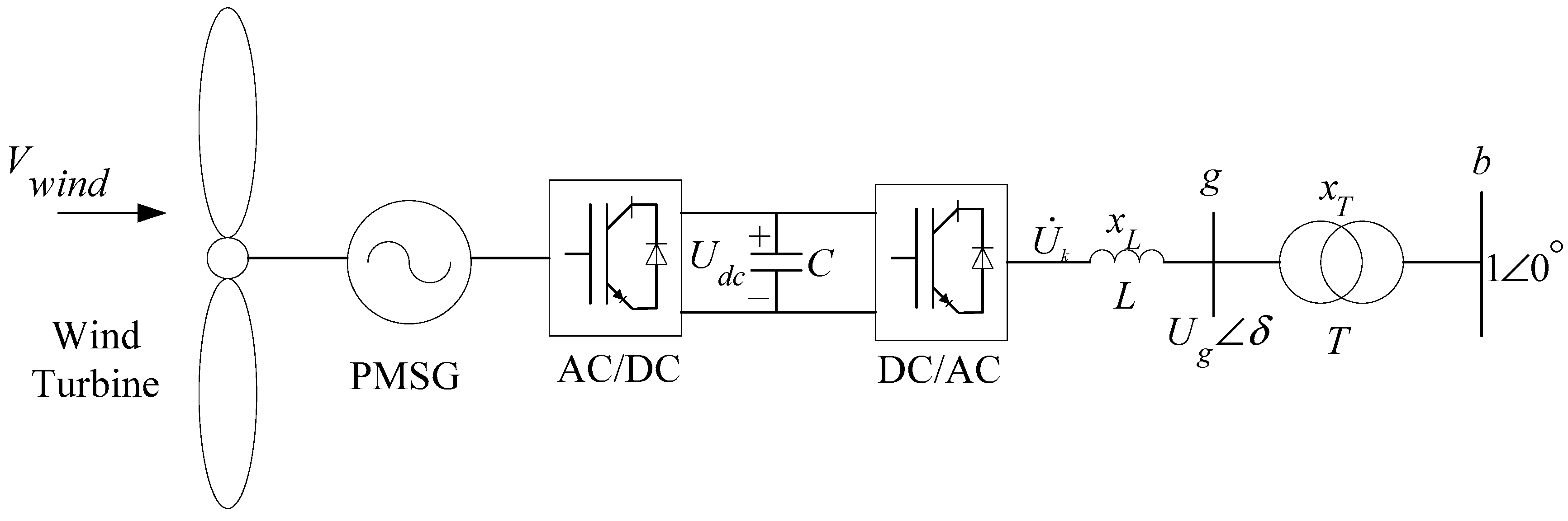
A microgrid consists of DGs, energy storages and loads, all of them are connected to the microgrid through inverters and their controllers. The detailed models of the components in the microgrid are the basis of the microgrid equivalent model. Wind generation is a common DG with different parts used in microgrids. A wind generation system is composed of a wind turbine, generator and control systems. Figure 1 shows the schematic diagram of the wind generation system, where a back-to-back converter is used to adjust the terminal voltage and frequency between the wind DG and the microgrid to improve the stability of the microgrid and realize the plug and play function of the DG [30].
The output power of the wind generation system is based on the wind turbine operational conditions, if the real wind speed is the rated wind speed. The wind generation system should operate at the maximum power tracking point, otherwise, the wind power system will produce constant power using the control of a pitch controller.
2.2. Photovoltaic System
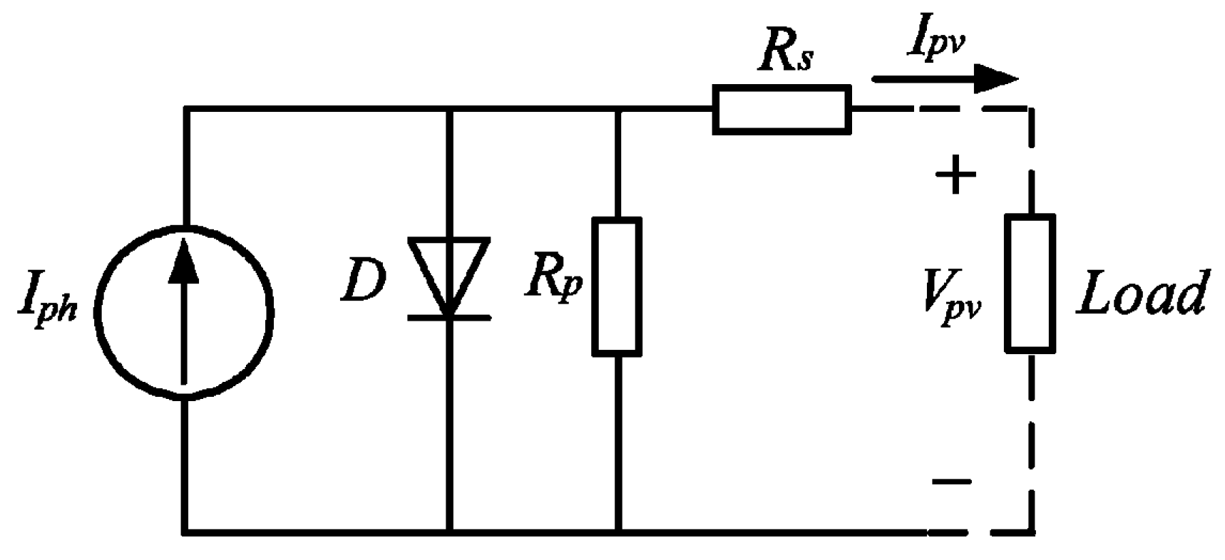
Photovoltaic power generation systems rely on the energy from the Sun, which is readily available to produce electricity using photovoltaic panels. A photovoltaic (PV) system is constituted by series and shunts of photovoltaic panels, and the output of the system changes with the temperature and illumination on the photovoltaic panels. Figure 2 shows the equivalent circuit of a photovoltaic cell in practical application, where it can be seen that terminal current and voltage of the PV cell can be represented by [31,32]:
where, Iph is photo-generatedcurrent which is proportional with illumination and PV panel area, IPV is the output current, and VPV is the terminal voltage. RS is the series resistance, Rsh is the shunt resistance. Vt is the junction thermal voltage that can be expressed by the equation Vt = ATK/q, where A is the quality factor of the diode, K is Boltzmann’sconstant, and T is the surface temperature of the PV cell.
The PV system connects into a microgrid through the PWM inverter to synchronize with the main network. The DC current generated by a PV panel should be converted into AC current to feed into the main network. In a PV system, the PV panel arrays are arranged in parallel with each other to improve the output power. Additionally, in order to ensure an adequate DC voltage, each string consists of a number of PV panels connected in series. The PV array can be seen as a voltage-source control (VSC) and be controlled based on a sinusoidal pulse-width modulation strategy.
2.3. Energy Storage System
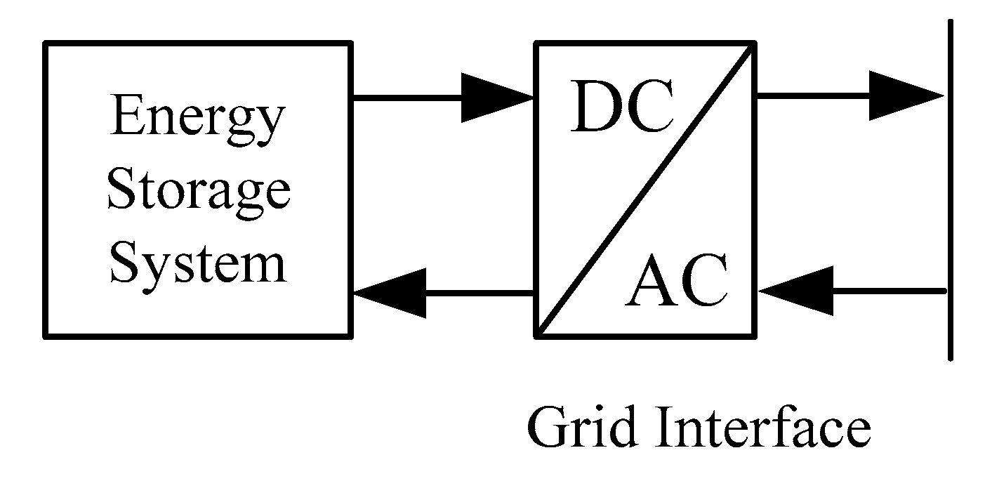
With the help of an energy storage system (ESS), a microgrid can maintain the instantaneous power balance more effectively and improve the dynamic performance through proper energy management strategies. An ESS can reduce the intermittency of DGs and strengthen the system inertia [30,33]. In a microgrid, an ESS acts as a buffer to absorb surplus power of the DG and compensate the insufficient power during the load peak.
Figure 3, shows an ESS connected to a microgrid through power an electronic inverter with a suitable control strategy. Typically, an ESS is constituted of various batteries with DC power and can be seen as a VSC system, a DC/AC pulse width modulation (PWM) inverter is needed to transform the DC system into an AC system. Filters are used for the compensation of the dead-time of the PWM controller.
2.4. Microgrid System Detailed Model
A microgrid consists of different types of DGs, energy storage systems and loads. The electrical and operational characteristics of DGs are so different that the control strategies of microgrid differ from one another under different load conditions. Furthermore, the operational conditions of a microgrid are based on meteorological factors, the electricity usage habits of users and the operational characteristics of the electrical equipment, etc. In a power system equivalent model, the measurement data of the boundary branch are collected to represent the external system behavior in the dynamic simulation.
An adequate mathematical differential-algebra equation representation of a power system can capture the nonlinear dynamic behavior of the original system. The behaviors of a microgrid are governed by the dynamics of its different components. Furthermore, there is a strong behavior coupling between them. Each component in a microgrid can be presented by a mathematical model with the voltage and power as the input and output, respectively, so the detailed model of a microgrid can be represented by a synthesis of components model. In a microgrid, the system behavior dynamics in different modes can be represented by differential-algebraic equations as follows:
where, x are the state variables, e.g., terminal voltage and current of DGs, the dynamic states of loads and controllers, etc. f are the differential equations, g are the algebraic equations. λ are the parameters of the microgrid components.
3. Microgrid Equivalent Modeling
3.1. Characteristic Model
The mathematical model of the original system should be sufficiently understood to meet the accuracy needs of the control performance. However, it is difficult to present an operating system accurately due to the circumstance that it is changing all the time. In some special conditions, the control system’s performance cannot be understood completely, and the mathematical model will not be accurate enough to get a good control result. The characteristic model is a system control method which is based on the dynamic characteristics of the original system and a reduced-order mathematical modeling method is used to represent the system performance.
The focus of this paper is to study the performance of the characteristic model for representing the dynamic of a microgrid. Characteristic modeling is a method to satisfy the dynamic characteristics and control performance of the objective, but does not satisfy the detailed accuracy objective analysis. As a nonlinear system, the output of the original system can be estimated based on the measured system. Measurement data contains the all characteristic information of the original system and the characteristic information can be extracted by some mathematical method such as a matrix, Prony, etc. A nonlinear system can be represented as follows:
where, x is the state variable and u is the input data of the system. If a system can be represented by the above nonlinear system and satisfies the following rules, the original system can be represented by the characteristic model:
- (1)
- The system is controllable.
- (2)
- The controllable variables are single order
- (3)
- If the state variables and input data equal zero: xi = ui = 0, then the function equals zero: f(k) = 0.
- (4)
- f(k) is a continuous derivative, and the partial derivatives are bounded.
The nonlinear system (3) will be linear and its Laplace transformation function can be presented as:
With the same input and steady state conditions, the responses of the original system and the equivalent characteristic model are equal when the sample time is small enough. Furthermore, the parameters of the characteristic model are slowly time-varying and bounded.
The original system can be described by the characteristic model and represented by the differential function with variable coefficients. The sum of all coefficients of the differential functions is equal to 1, while satisfying the following conditions:
If original system G(s) is stable or has integral element, then the coefficients fi(k) and gi(k) and are slowly time-varying, and the bound of the coefficients can be pre-confirmed. Under steady state, the sum of all coefficients is equal to one which can be presented as f1(∞) + f2(∞) + g0(∞) + g1(∞) = 1. However, if system has an integral element, then f1(∞) + f2(∞) = 1.
As the corollary, in order to represent the original system more accurately, a high order characteristic model can be used to represent the dynamics of the original system and the range of its coefficients is:
The derivation of the characteristic model involves the approximation of each term in the original with a 2nd-order ordinary differential equation and judiciously combining many such 2nd-order ordinary differential equations to result in a single 2nd-order time-varying differential equations with the properties as stated. Naturally, when the system model contains terms with a higher order, the characteristic model will be of a higher order.
3.2. Coefficient
The coefficient of the two-order characteristic model contains f1(k), f2(k), g0(k) and g1(k).To facilitate the identification of its coefficients, the characteristic model can be rewritten as y(k + 1) = ϕT(k)θ(k),where:
is the identified parameter of vector θ(k) which contains the coefficients in characteristic model. Then, the error ε(k) of the system output can be represented as:
will be updated by the adaptive gradient law along with a parameter projection as follows:
where, δ > 0, 0 < τ < 1. For the vector x ∈ R4, π(x) is the projection of x into the set Ψ.
3.3. Microgrid Equivalent Modeling Based on Characteristic Model
As stated in the Introduction, the aim of this paper is to find an equivalent model for a grid-tied microgrid. As shown in Figure 4, the microgrid contains DGs, storage system and different loads. Most DGs connect to a microgrid through inverters with complex dynamic behaviors. The detailed model of components is nonlinear and complex, which will impose a heavy calculation burden with the high dimension differential algebra equations of the electrical equipment in real time dynamic analysis of the power system. Figure 4 gives the concept of equivalent modeling of a grid-tied microgrid.
From the distribution network viewpoint, a microgrid can be seen as a controlled component. Under grid-tied mode, there is power exchange between the microgrid and the distribution network. The microgrid will absorb power from the distribution network when the output power of the DGs is not enough. It also exports surplus power to the distribution network, respectively. The voltage, current and exchange power of the PCC determine the dynamic information of the distributed components and their control policy. Based on the characteristic modeling theory, the complex microgrid can be simplified as a characteristic model in engineering applications and not lose any information. The equivalent model of a microgrid can be written as a 2nd-order differential equation, where the voltage and exchange power of the PCC are the input and output of the model, respectively:
where, ui is the PCCvoltage, P and Q are the power exchanged between the microgrid and the distribution network, a = [a11, …, a234] are the parameters of the model which should be identified, t is the time sample.
3.4. Parameter Identification Based on Recursive DampedLeast SquaresAlgorithm
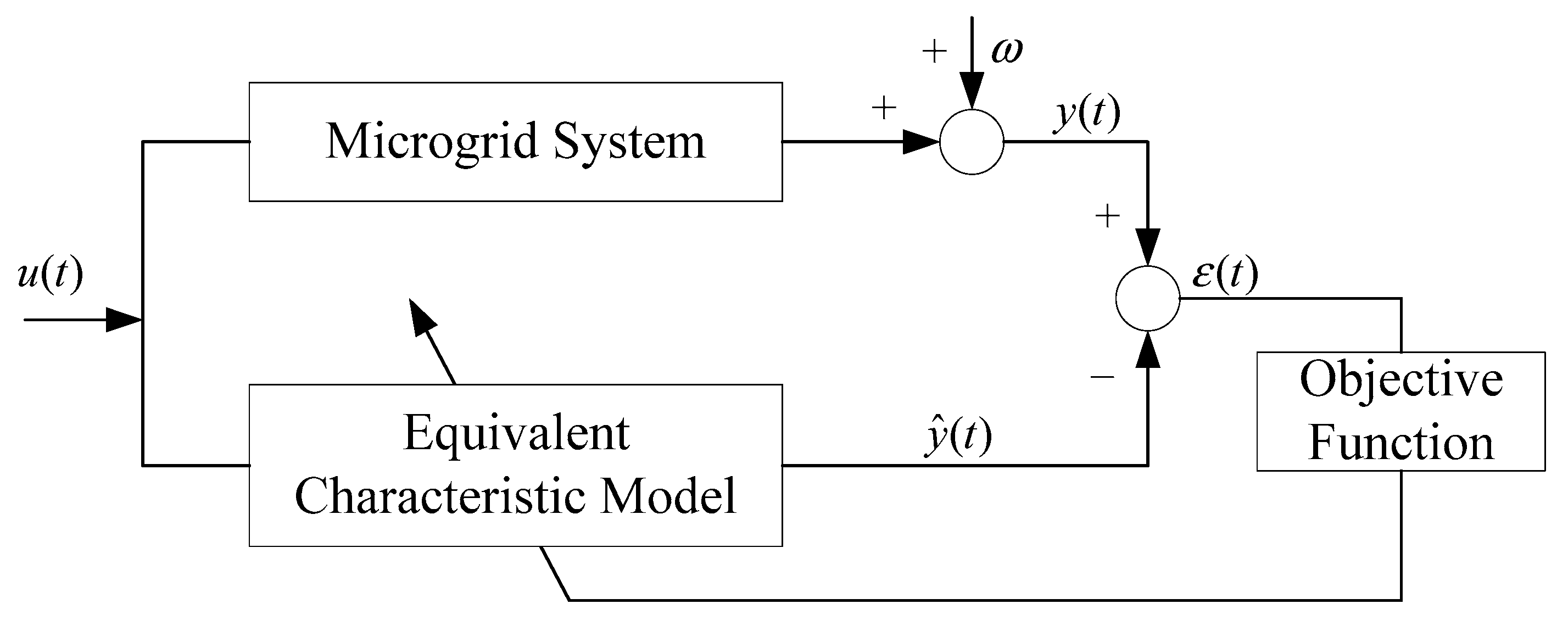
The recursive damped least squares algorithm (RDLS) has been widely used to identify model parameters for equalization. RDLS has the features of faster convergence and higher accuracy. The DRLS function is to find a vector that minimizes the energy difference between the measurement data and the identified output of the model. As shown in Equation (11), for a Multiple-Input Multiple-Output (MIMO) system, Y is usually a reference signal that can be measured from the original system, H is the observation vector that presents the function of the output of the system affected by non-ideal effects. θ are the model parameters which minimize the error between the measurement data and output of the equivalent model. The modeling process is shown in Figure 5. The objective function of the RDLS method may be written as indicated in Equation (12):
where, V is the system noise or measured error, is the objective of recursive damped least squares identification, μ is a damped factor, λ is a forgetting factor which belongs to the range (0, 1). It is a fast forgetting rate with a forgetting litter change factor λ. The algorithm finds the set of parameters which turns the output of the original system into the corrected output . The process of the recursive solution can be written as:
With the recursive algorithm, T(t)may be written as:
where, ri is the subsequent vector of r1, and r1 = [1, 0, …, 0]T, μ’ = (1 – λ)μ/k and in the equivalent modeling process, the outputs Y(k) are the active power and reactive power of the microgrid Y(k) = [P(k); Q(k)].
4. Results and Discussion
4.1. Simulation System
A test microgrid system is built in DIgSILENT to verify the proposed microgrid characteristic equivalent modeling method. The microgrid is constituted by a wind power system, photovoltaic system, storage system, motor and a traditional load like a Constant-Impedance, Constant-Current and Constant-Power (ZIP) load. The microgrid is connected to the distribution network through a 10 kV/20 kV transformer which is shown in Figure 6. PV is considered to be derived from a DC voltage source and through a PWM controller to connect to the microgrid, and the ESS, also derived from a DC source, connects to the microgrid through a bidirectional VSC PWM controller. The ESS can improve the voltage stability of the microgrid. The reference frequency is 50 Hz and the voltage of the microgrid bus is 10 kV, while the distribution network is a standard benchmark medium voltage distribution network as modeled in [16]. Under the grid-tied mode, constant power control is chosen as the output power control of DG, which is to improve the effective use of the renewable energy. The output rated wind power capacity is 2.4 MVA, the rated capacity of the PV system is 1 MVA, the rated capacity of the gas turbine is 8 MVA, and the rated capacity of load 1 and load 2 are 2 MVA and 5 MVA, respectively.
4.2. Measurement Data
The microgrid contains different components, and the interaction between the components is different during the different operational scenarios. During the grid-tied mode, effective measurement data is important for the parameter identification. The measurement data must contain the dynamic behavior information of the microgrid, so the dynamic measurement data should be collected based on the faults which can motivate the essential characteristics of the microgrid. In this paper, the measurement data is based on a relatively drastic fault like a three-phase short circuit in the distribution network, and the microgrid still operates at the grid-tied mode. At this condition, the fault in the distribution network will drive the essential characteristics of the components in the microgrid. Other measurement data should be collected to test the obtained model under different fault conditions of the microgrid and DG.
The sample time of the measurement data also is an important factor for the equivalent modeling. If the sample is too small, like microseconds, it will increase the calculation burden but without improving the accuracy of the modeling. If the sample is 1 s, it is not accurate enough get an electromechanical microgrid equivalent model. In this paper, the sample time of the measurement data is 1millisecond, the fault time is 5 cycles, and the measurement data contains voltage, current and the power of the PCC. During the fault period, the power exchanged between the microgrid and the distribution network fluctuates very severely, and system will return to a steady state when the fault is cleared. From the distribution network viewpoint, the microgrid can be seen as a single point connected through the PCC, so the power, voltage and current dynamics of the PCC contain the inherent characteristics of the whole microgrid.
4.3. Characteristic Modeling Based on Faults
As shown in Equation (10), the characteristic model is a 2nd-order differential equation where the power and the voltage are the output and input of the equivalent model, respectively. The characteristic model can be written as:
where, P(k) and Q(k) are the active and reactive power sequence of the microgrid output, respectively. The equivalent model parameters can be written as θ = [a11, a12, a113, a123, a114, a124, a21, a22, a213, a223, a214, a224]T, the observation vector H is the matrix of the previous power and voltage. During the parameter identification, the forgetting factor and damped factor are important for the accuracy of the parameters. In this paper, the forgetting factor λ = 0.999 and the damped factor μ = 0.6, which is based on the experimental results.
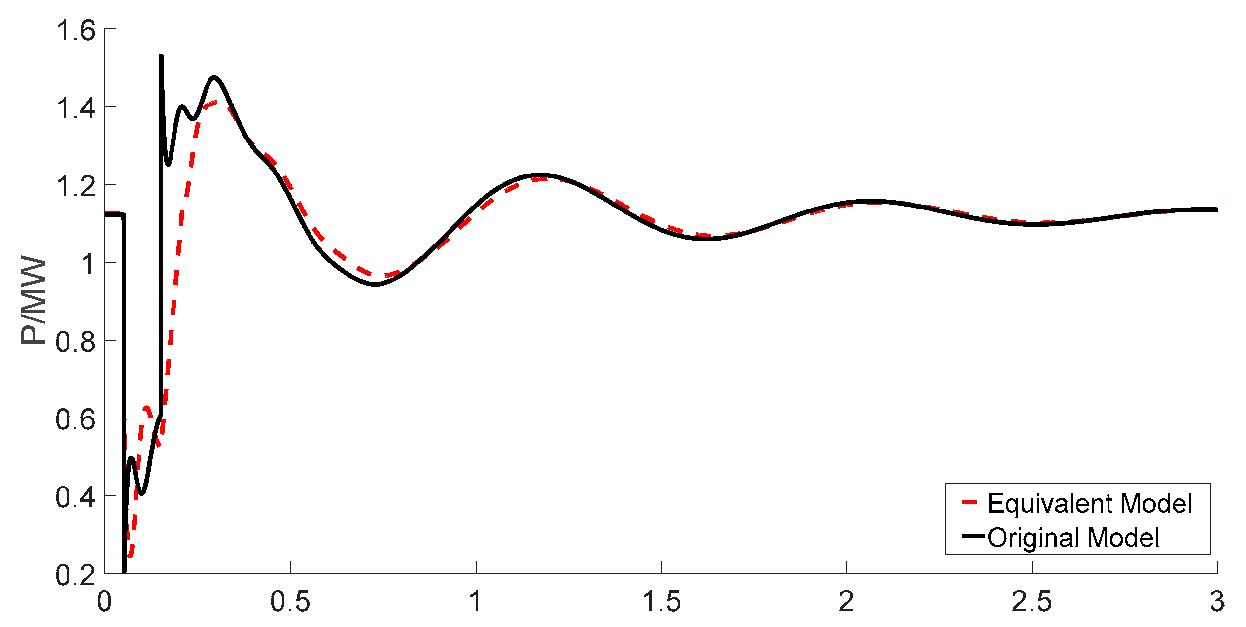
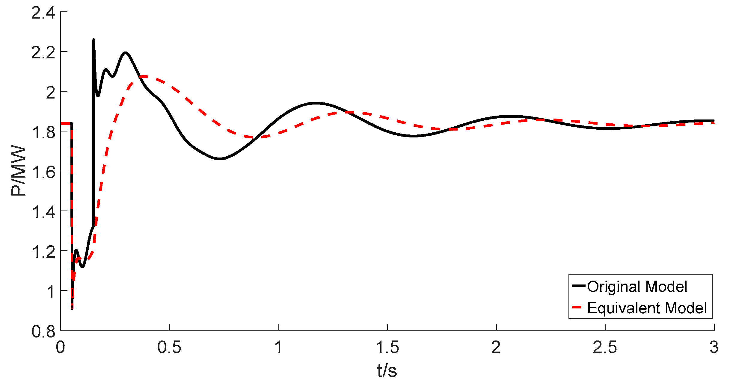
Figure 7 and Figure 8 show the comparison between the original system and the characteristic model of the microgrid during the fault with the measurement data sets. It shows that the errors between equivalent model and the original system are small enough, and the equivalent model can track the original system during the dynamic process. Under grid-tied mode, the output active power of the components in the microgrid is controlled accurately. However, the reactive power balance of the microgrid is controlled through the distribution network in grid-tied mode. Figure 9 shows the parameter dynamics during the recursive process, the identified parameters of the equivalent model are shown in Table 1. Figure 10 shows the response of the active power under another fault with the same microgrid construction. It can be seen that the equivalent model can match the original system well.
The characteristic equivalent method is compared with other modeling method in the literature. The characteristic equivalent method is a non-mechanism equivalent modeling method, and the significant merits of the non-mechanism format are calculation speed and engineering applicability. With the RDLS, the parameters can be identified quickly and the parameters are time-varying. On-line analysis calculation of a distribution network needs a fast calculation of the microgrid model, but it does not need to know the detailed information of the microgrid itself. The calculation comparison between the proposed method and the method referred to in [16] are shown in Table 2. The results show that characteristic modeling of microgrids is easier and faster than the mechanism method. The average error is defined as the output difference between equivalent model and original model:
where, Pr(t) and Qr(t)are the microgrid output power measurement data, and Peq(t) and Qeq(t)are the output power of the equivalent model.
4.4. Model Development
To evaluate the proposed model performance, the microgrid was tested under different scenarios and operational conditions. Additionally, faults caused by different drivers are applied. The microgrid operates indifferent scenarios during the daytime, when normally, the output power of the PV system is varying with the Sun position, and the load profile is different over time, so the operation of the microgrid is different under different conditions. Here, in order to develop the equivalent model, several typical scenarios are extracted for testing the performance of the equivalent model. In all of the scenarios, the DGs such as wind power and PV system work under a PQ control strategy and the MPPT state to improve the utility of the renewable energy.
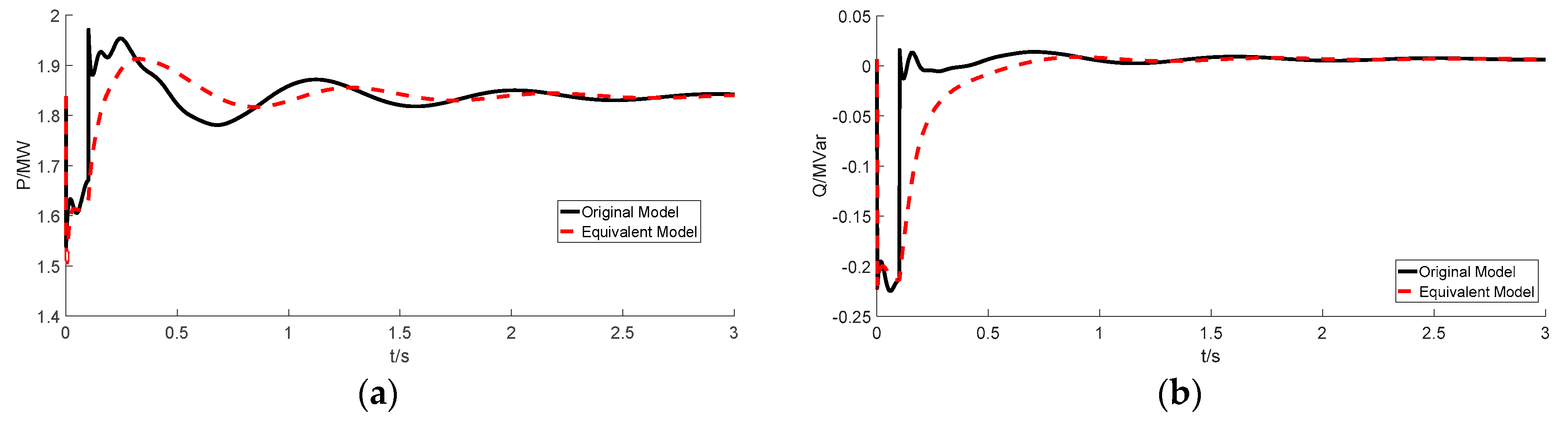
Scenario 1: Based on the weather, the output power of the PV system will decrease to 30%, or the output power of the PV system will disappear in the evening. In this scenario, the equivalent model can match the change of PV system in the microgrid. Figure 11 shows that the equivalent model agrees well with the original system. With the decrease of PV system output, the microgrid will absorb more power from the distribution network, but the components of the microgrid do not change, and the microgrid dynamics are similar to the experimental scenario. A single phase grounded short circuit fault is applied in Scenario 1, Figure 12 shows the active and reactive power response of the microgrid in Scenario 1, where it can be seen that the equivalent model can represent the dynamics of the microgrid during different faults.
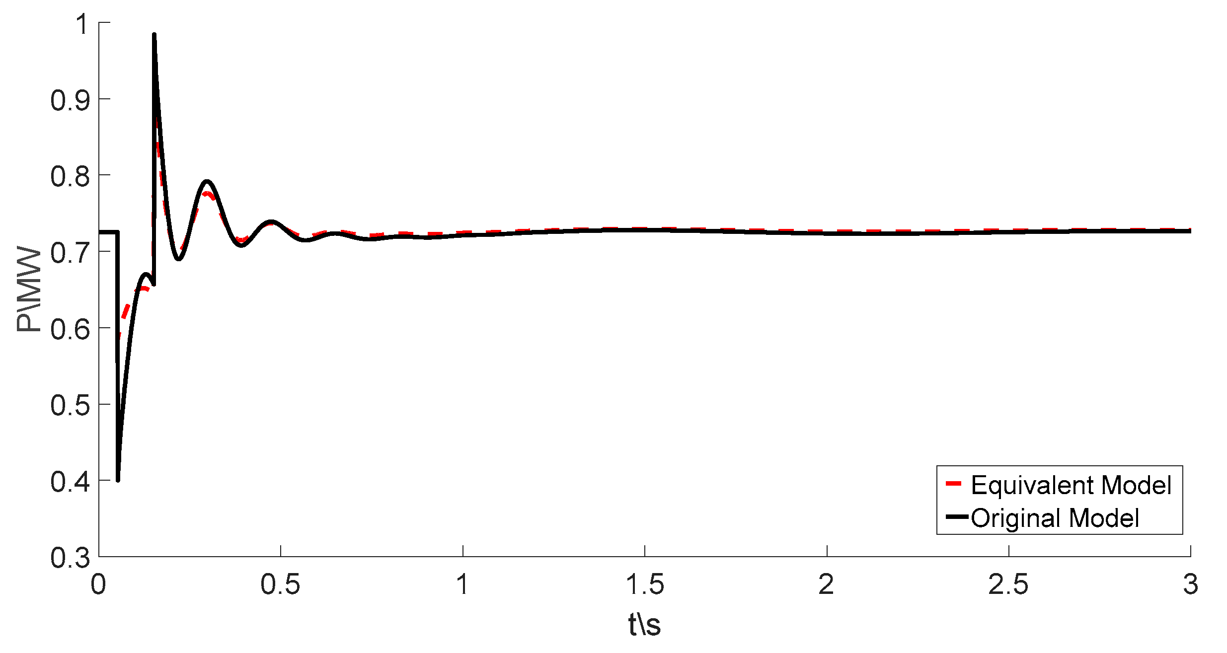
Scenario 2: Load 1 is removed, and the reserve load about 30% of the total load. The active power of the microgrid in the PCC is shown in Figure 13. It can be seen that with the load shedding, the microgrid will inject the surplus power into the distribution network. However, the components in the microgrid do not change which makes the dynamics of the microgrid similar to the experimental scenario. Figure 13 shows that the PCC active power dynamic response agrees well with the original system.
Scenario 3: Based on Scenario 2, the gas turbine is shut down. Figure 14 shows the comparison between the equivalent model and original model. In this microgrid, the gas turbine is the main DG which maintains the grid frequency and voltage of microgrid in the islanded mode. In grid-tied mode, the operational state of the gas turbine relies on the price information of the distribution network. Here, the gas turbine is not running, and the dynamics of the microgrid are fully different from the former scenarios. However, the dynamics of the equivalent model can track the original system during a fault too.
5. Conclusions
A non-mechanism dynamic equivalent modeling method based on a characteristic model is proposed in this paper which is used for the simulation of the dynamic response of a microgrid in grid-tied mode. The proposed method can give the equivalent model of the microgrid but does not need the detailed topologicalstructure and parameters of the microgrid itself. The equivalent reduced order model can track the dynamic response of the original system and not lose any parameter information. In the modeling process, the operational variables such as voltage and power of the PCC are measured for the training dataset to extract the characteristic information of the microgrid. The parameters of the equivalent model have been identified using a RDLS algorithm. Simulation results in different operation scenarios show the effectiveness of the proposed equivalent modeling method. The proposed equivalent model can represent the dynamic response behaviors of microgrids under different operation scenarios. It can also improve the modeling efficiency.
Acknowledgment
This paper is supported by the national Natural Science Foundation of China (51607057, 51207043, 61501171), the Fundamental Research Funds for the Central Universities (2017B21214), Science and Technology Project of State Grid (NY71-16-024), The authors are also grateful to College of the Internet of Things Engineering and Jiangsu Key Laboratory of Power Transmission & Distribution Equipment Technology, at Hohai University, China.
Author Contributions
Changchun Cai proposed the equivalent modeling method of microgrid and designed the experiments and written the article, Haolin Liu and Weili Dai performed the experiments, Other authors helped to collect data and revise the paper.
Conflicts of Interest
The authors declare no conflicts of interest.
References
- Venkata, S.S.; Pahwa, A.; Brown, R.E.; Christie, D.R. What future distribution engineers need to learn. IEEE Trans. Power Syst. 2004, 19, 17–23. [Google Scholar] [CrossRef]
- Chen, C.; Wang, J.H.; Qiu, F. Resilient distribution system by microgrids formation after natural disasters. IEEE Trans. Smart Grid 2016, 7, 958–966. [Google Scholar] [CrossRef]
- Ou, T.C.; Hong, C.M. Dynamic operation and control of microgrid hybrid power systems. Energy 2014, 66, 314–323. [Google Scholar] [CrossRef]
- Simpson-Porco, J.W.; Dorfler, F.; Bullo, F. Voltage stabilization in microgrids via quadratic droop control. IEEE Trans. Autom. Control 2017, 62, 1239–1253. [Google Scholar] [CrossRef]
- Ou, T.C. A novel unsymmetrical faults analysis for microgrid distribution systems. Int. J. Electr. Power Energy Syst. 2012, 43, 1017–1024. [Google Scholar] [CrossRef]
- Jedrzejczak, J.; Anders, G.J.; Fotuhi-Firuzabad, M.; Farzin, H.; Aminifar, F. Reliability assessment of protective relays in harmonic polluted power systems. IEEE Trans. Power Deliv. 2017, 32, 556–564. [Google Scholar] [CrossRef]
- Arya, S.R.; Singh, B.; Niwas, R.; Chandra, A.; Ai-Haddad, K. Power quality enhancement using DSTATCOM in distributed power generation system. IEEE Trans. Ind. Appl. 2016, 52, 5203–5212. [Google Scholar] [CrossRef]
- Rasheduzzaman, M.; Mueller, J.A.; Kimball, J.W. Reduced-order small-signal model of microgrid systems. IEEE Trans. Sustain. Energy 2015, 6, 1295–1305. [Google Scholar] [CrossRef]
- Tang, X.; Deng, W.; Qi, Z. Investigation of the dynamic stability of microgrid. IEEE Trans. Power Syst. 2014, 29, 698–706. [Google Scholar] [CrossRef]
- Olivares, D.E.; Mehrizi-Sani, A.; Etemadi, A.H.; Canizares, C.A.; Iracani, R.; Kazerani, M.; Hajimiragha, A.H.; Saeedifard, M.; Gomis-Bellmunt, O.; Palma-Behnke, R.; et al. Trends in microgrid control. IEEE Trans. Smart Grid 2014, 5, 1905–1919. [Google Scholar] [CrossRef]
- Lasseter, R.; Akhil, A.; Marnay, C.; Stephens, J.; Dagle, J.; Guttromson, R.; Meliopoulous, A.S.; Yinger, R.; Eto, J. Integration of Distributed Energy Resources: The CERTS MicroGrid Concept. Available online: http://escholarship.org/uc/item/9w88z7z1#page-1 (accessed on 16 October 2017).
- Ourari, M.L.; Dessaint, L.A.; Do, V.Q. Dynamic equivalent modeling of large power systems using structure preservation technique. IEEE Trans. Power Syst. 2006, 21, 1284–1295. [Google Scholar] [CrossRef]
- Kim, A.R.; Seo, H.R.; Kim, G.H.; Park, M.W.; Yu, I.K.; Otsuki, Y.; Tamura, J.; Kim, S.H.; Sim, K.D.; Seong, K.C. Operating characteristic analysis of HTS SMES for frequency stabilization of dispersed power generation system. IEEE Trans. Appl. Supercond. 2010, 20, 1334–1338. [Google Scholar]
- Zhao, B.; Zhang, X.S.; Chen, J. Integrated Microgrid Laboratory System. IEEE Trans. Power Syst. 2012, 27, 2175–2185. [Google Scholar] [CrossRef]
- Ju, P.; Ni, L.Q.; Wu, F. Dynamic Equivalents of Power Systems with Online Measurements. Part 1: Theory. IEE Proc. Gener. Trans. Distrib. 2004, 151, 175–178. [Google Scholar] [CrossRef]
- Cai, C.C.; Jiang, B.; Deng, L.H. General Dynamic Equivalent Modeling of Microgrid Based on Physical Background. Energies 2015, 8, 12929–12948. [Google Scholar] [CrossRef]
- Cai, C.C.; Cao, X.Q. Equivalent Simplification Method of Micro-grid. Telkomnika 2013, 11, 5461–5470. [Google Scholar]
- Zha, X.M.; Zhang, Y.; Cheng, Y.; Fan, Y.P. New method of extended coherency for Microgrid based on homology in differential geometry. Trans. China Electr. Soc. 2012, 27, 24–31. [Google Scholar]
- Resende, F.O.; Lopes, J.A.P. Development of dynamic equivalents for microgrids using system identification theory. In Proceedings of the 2007 IEEE Lausanne Power Tech, Lausanne, Switzerland, 1–5 July 2007; pp. 1033–1038. [Google Scholar]
- Stankovic, A.M.; Saric, A.T. Transient power system analysis withmeasurement-based gray box and hybrid dynamic equivalents. IEEE Trans. Power Syst. 2004, 19, 455–462. [Google Scholar] [CrossRef]
- Milanovic, J.V.; Zali, S.M. Generic Model of Active Distribution Network for Large Power System Stability Studies. IEEE Trans. Power Syst. 2013, 28, 3126–3133. [Google Scholar]
- Azmy, A.M.; Erlich, I.; Sowa, P. Artificial Neural Network-Based Dynamic Equivalents for Distribution Systems Containing Active Sources. IEE Proc. Gener. Trans. Distrib. 2004, 151, 681–688. [Google Scholar] [CrossRef]
- PPapadopoulos, N.; Papadopoulos, T.A.; Crolla, P.; Roscoe, A.J.; Papagiannis, G.K.; Butt, G.M. Black-box dynamic Equivalent Model for Microgrids Using Measuring Data. IET Gener. Trans. Distrib. 2014, 8, 851–861. [Google Scholar] [CrossRef] [Green Version]
- Papadopoulos, P.N.; Papadopoulos, T.A.; Crolla, P.; Roscoe, A.J.; Papagiannis, G.K.; Burt, G.M. Measurement-Based Analysis of the Dynamic Performance of Microgrids Using System Identification Techniques. IET Gener. Trans. Distrib. 2015, 9, 90–103. [Google Scholar] [CrossRef]
- Kumar Nunna, H.; Doolla, S. Multiagent-based distributed-energy-resource management for intelligent microgrids. IEEE Trans. Ind. Electron. 2012, 60, 1678–1687. [Google Scholar] [CrossRef]
- Gomez-Sanz, J.J.; Garcia-Rodriguez, S.; Cuartero-Soler, N.; Hernandez-Callejo, L. Reviewing microgrids from a multi-agent systems perspective. Energies 2014, 7, 3355–3382. [Google Scholar] [CrossRef]
- Wu, H.X.; Hu, J.; Xie, Y.C.; Meng, B.; Lin, Z.L. Theory and Applications of Characteristic Modeling: An Introductory Overview. Int. J. Intell. Control Syst. 2015, 20, 1–8. [Google Scholar]
- Zhou, C.J.; Shi, Y.F.; Yang, S.H.; Yin, Q.; Qin, Y.Q. Characteristic Model-Based Adaptive Discrete-Time Sliding Mode Control for the Swing Arm in a Fourier Transform Spectrometer. IEEE Trans. Syst. Man Cybern. Part C Appl. Rev. 2012, 42, 1633–1643. [Google Scholar] [CrossRef]
- Wu, Y.F.; Wang, Z.H.; Li, Y.Y.; Chen, W.; Du, R.H.; Chen, Q.W. Characteristic Modeling and Control of Servo Systems with Backlash and Friction. Math. Probl. Eng. 2014, 2014, 328450. [Google Scholar] [CrossRef]
- Han, J.; Solanki, S.K.; Solanki, J. Coordinated Predictive Control of a Wind/Battery Microgrid System. IEEE J. Emerging Sel. Top. Power Electr. 2013, 1, 296–305. [Google Scholar] [CrossRef]
- Campanhol, L.B.G.; Silva, S.A.O.; Oliveira, A.A.; Bacon, V.D. Single-Stage Three-Phase Grid-Tied PV System With Universal Filtering Capability Applied to DG System and AC Microgrids. IEEE Trans. Power Electr. 2017, 32, 9131–9142. [Google Scholar] [CrossRef]
- Wu, D.; Tang, F.; Dragicevic, T.; Vasquez, J.C.; Guerrero, J.M. Autonomous Active Power Control for Islanded AC Microgrids With Photovoltaic Generation and Energy Storage System. IEEE Trans Energy Convers. 2014, 29, 882–892. [Google Scholar] [CrossRef]
- Thale, S.S.; Wandhare, R.G.; Agarwal, V. A Novel Reconfigurable Microgrid Architecture with Renewable Energy Sources and Storage. IEEE Trans. Ind. Appl. 2015, 51, 1805–1816. [Google Scholar] [CrossRef]
Figure 1.
Wind generation system.

Figure 2.
Equivalent circuit of a photovoltaic cell.

Figure 3.
Energy storage system (ESS).

Figure 4.
Concept of microgrid equivalent modeling.
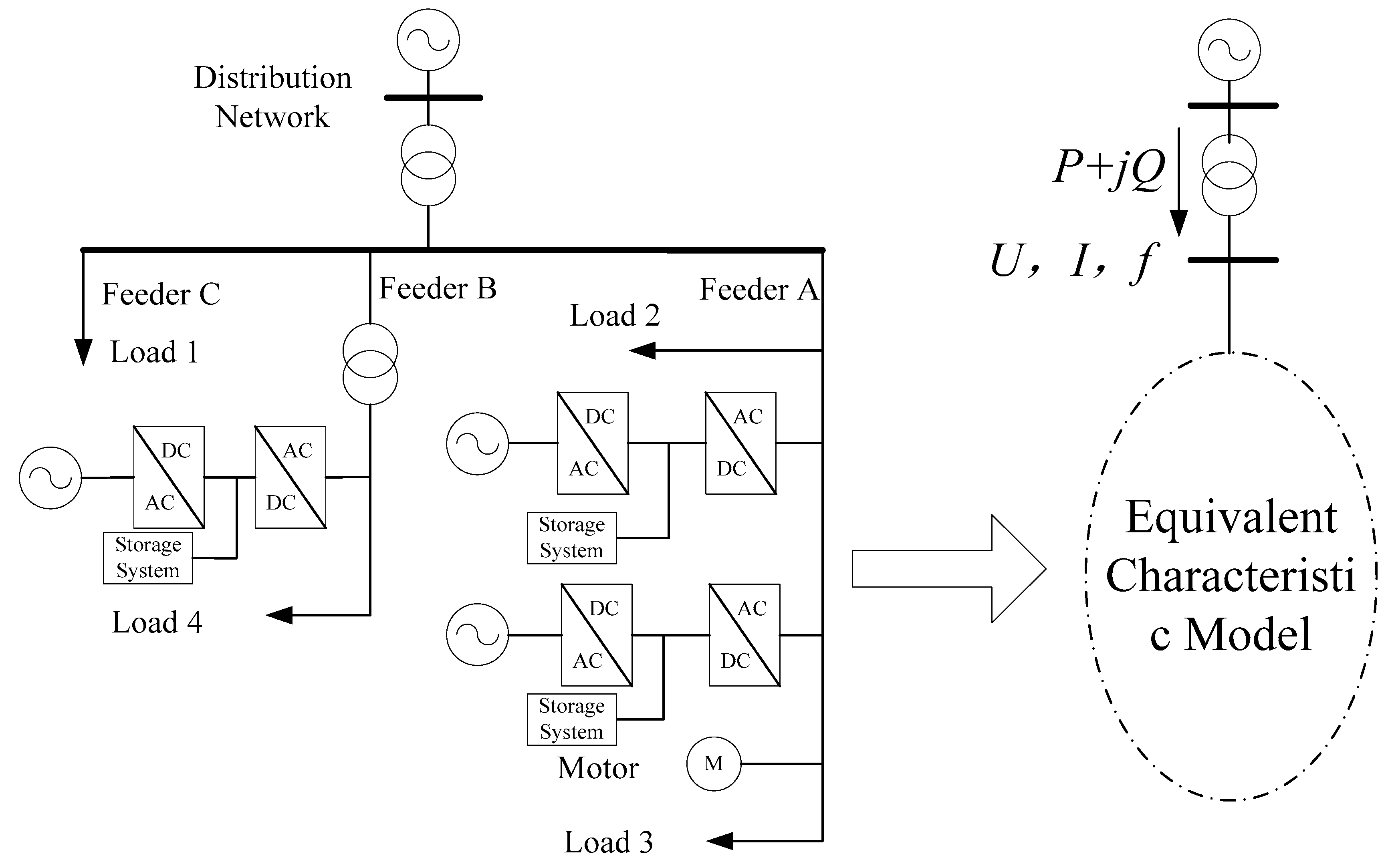
Figure 5.
Characteristic modeling process.

Figure 6.
Microgrid system. PCC: point of common couple.
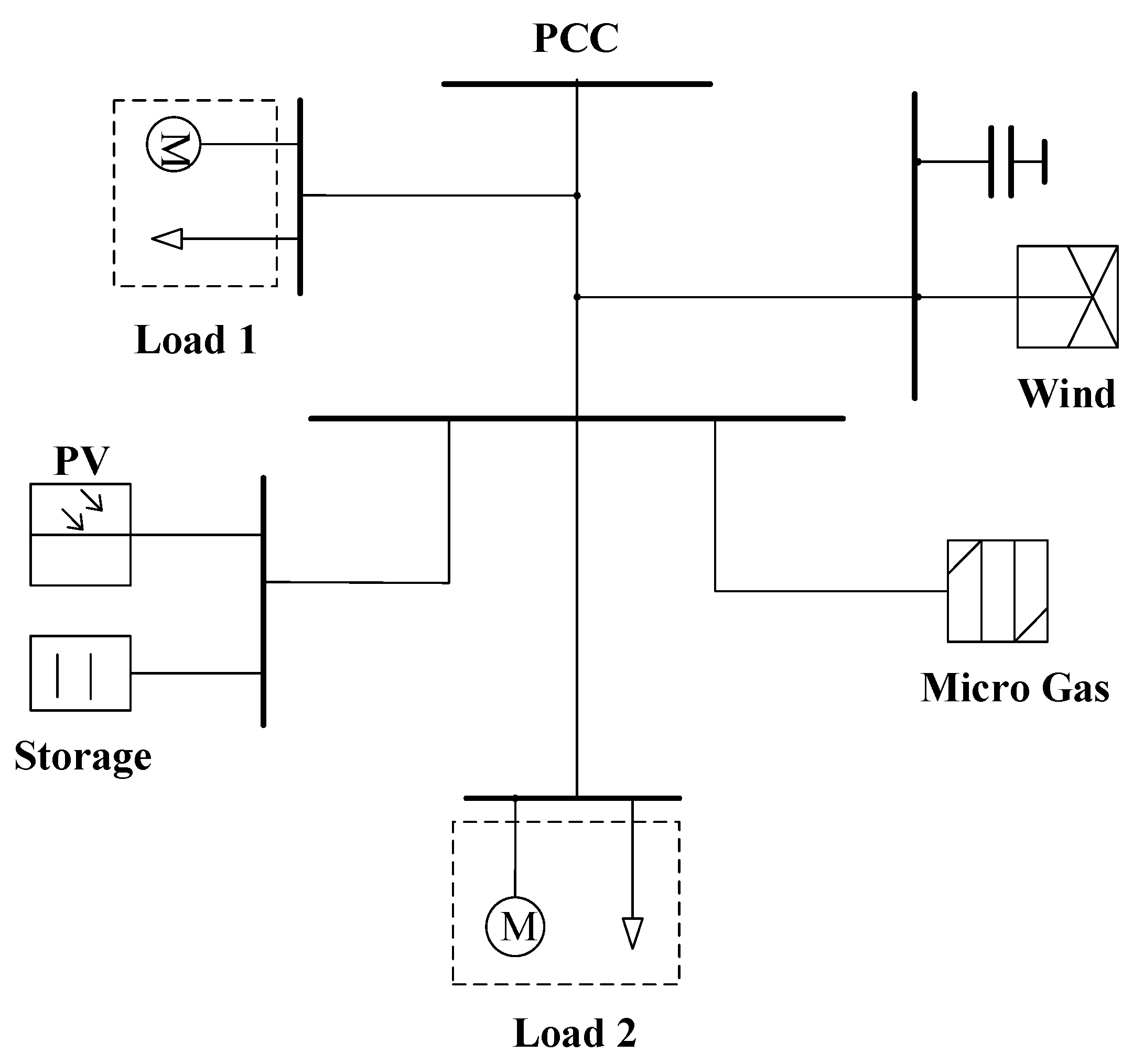
Figure 7.
Active power of the PCC.

Figure 8.
Reactive power of the PCC.
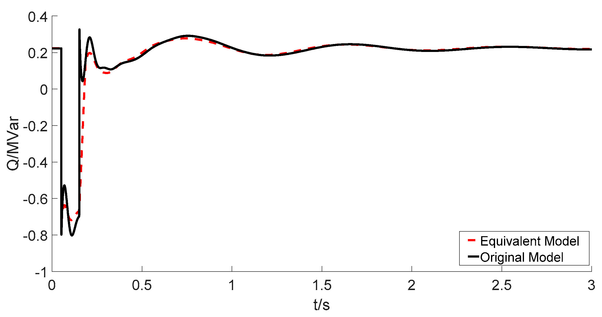
Figure 9.
The parameter identification process.
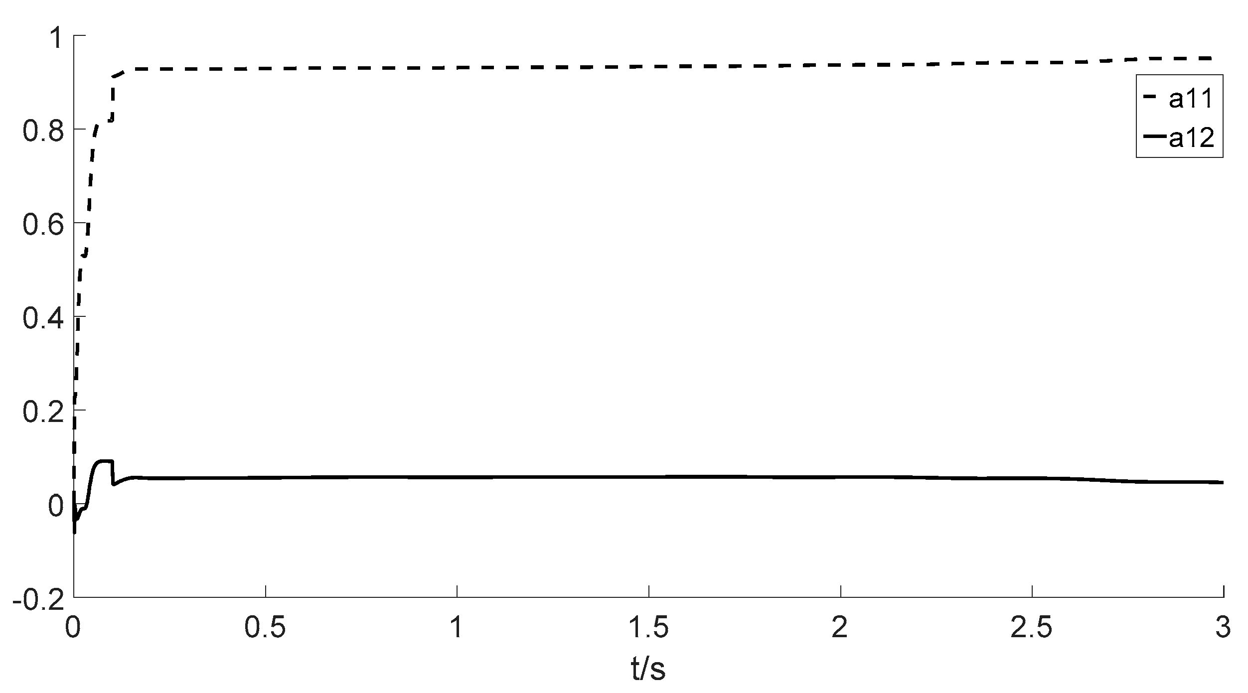
Figure 10.
The active power response under single fault conditions.
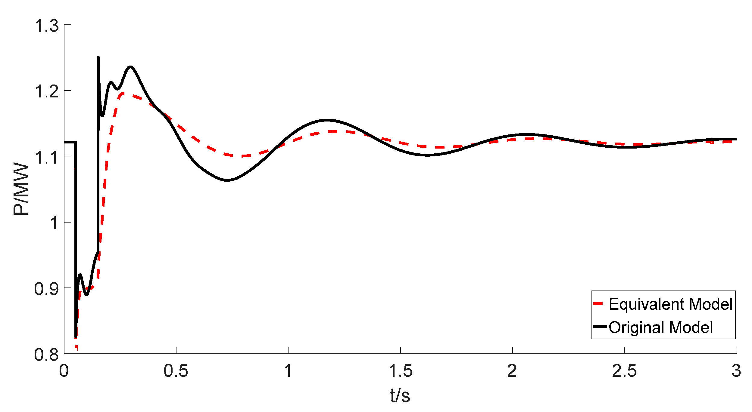
Figure 11.
The response of the microgrid under Scenario 1.

Figure 12.
(a) Active and (b) reactive response under single phase grounded short circuit conditions.
Figure 12.
(a) Active and (b) reactive response under single phase grounded short circuit conditions.

Figure 13.
The active response of the microgrid in Scenario 2.
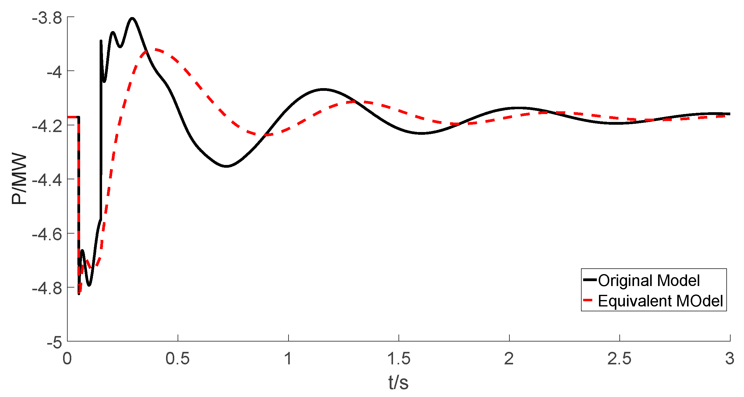
Figure 14.
The response of the microgrid in Scenario 3.


Table 1.
The parameters of the equivalent model.
| 1.0467 | −0.0486 | −0.0190 | 0.0199 | −0.0771 | −0.0534 |
| 0.9519 | 0.0452 | 0.0061 | −0.0012 | 0.0418 | 0.0373 |
Table 2.
The comparison of consuming time between different modeling methods.
| Method | Average Time (s) | Average Error |
|---|---|---|
| Characteristic modeling | 0.2159 | 0.98652 |
| Mechanism Modeling [16] | 3.1524 | 1.08623 |
© 2017 by the authors. Licensee MDPI, Basel, Switzerland. This article is an open access article distributed under the terms and conditions of the Creative Commons Attribution (CC BY) license (http://creativecommons.org/licenses/by/4.0/).
Share and Cite
MDPI and ACS Style
Cai, C.; Liu, H.; Dai, W.; Deng, Z.; Zhang, J.; Deng, L. Dynamic Equivalent Modeling of a Grid-Tied Microgrid Based on Characteristic Model and Measurement Data. Energies 2017, 10, 1951. https://doi.org/10.3390/en10121951
AMA Style
Cai C, Liu H, Dai W, Deng Z, Zhang J, Deng L. Dynamic Equivalent Modeling of a Grid-Tied Microgrid Based on Characteristic Model and Measurement Data. Energies. 2017; 10(12):1951. https://doi.org/10.3390/en10121951
Chicago/Turabian StyleCai, Changchun, Haolin Liu, Weili Dai, Zhixiang Deng, Jianyong Zhang, and Lihua Deng. 2017. "Dynamic Equivalent Modeling of a Grid-Tied Microgrid Based on Characteristic Model and Measurement Data" Energies 10, no. 12: 1951. https://doi.org/10.3390/en10121951
Note that from the first issue of 2016, this journal uses article numbers instead of page numbers. See further details here.