Article

Experimental and One-Dimensional Mathematical Modeling of Different Operating Parameters in Direct Formic Acid Fuel Cells

by
Shingjiang Jessie Lue
1,2,3,*,
Nai-Yuan Liu
1,
Selvaraj Rajesh Kumar
1,
Kevin Chi-Yang Tseng
1,
Bo-Yan Wang
1 and
Chieh-Hsin Leung
1
1
Department of Chemical and Materials Engineering and Green Technology Research Center, Chang Gung University, Guishan District, Taoyuan City 333, Taiwan
2
Department of Radiation Oncology, Chang Gung Memorial Hospital, Guishan District, Taoyuan City 333, Taiwan
3
Department of Safety, Health and Environment Engineering, Ming-Chi University of Technology, Taishan, New Taipei City 243, Taiwan
*
Author to whom correspondence should be addressed.
Energies 2017, 10(12), 1972; https://doi.org/10.3390/en10121972
Submission received: 15 October 2017 / Revised: 20 November 2017 / Accepted: 23 November 2017 / Published: 27 November 2017
(This article belongs to the Section L: Energy Sources)

Abstract

:
The purpose of this work is to develop a one-dimensional mathematical model for predicting the cell performance of a direct formic acid fuel cell and compare this with experimental results. The predicted model can be applied to direct formic acid fuel cells operated with different formic acid concentrations, temperatures, and with various electrolytes. Tafel kinetics at the electrodes, thermodynamic equations for formic acid solutions, and the mass-transport parameters of the reactants are used to predict the effective diffusion coefficients of the reactants (oxygen and formic acid) in the porous gas diffusion layers and the associated limiting current densities to ensure the accuracy of the model. This model allows us to estimate fuel cell polarization curves for a wide range of operating conditions. Furthermore, the model is validated with experimental results from operating at 1–5 M of formic acid feed at 30–80 °C, and with Nafion-117 and silane-crosslinked sulfonated poly(styrene-ethylene/butylene-styrene) (sSEBS) membrane electrolytes reinforced in porous polytetrafluoroethylene (PTFE). The cell potential and power densities of experimental outcomes in direct formic acid fuel cells can be adequately predicted using the developed model.

1. Introduction

The research into fuel cell rockets has increased in the last decades, the direct formic acid fuel cells (DFAFCs) is considered to be a potential alternative power supply to the direct methanol fuel cell (DMFC), especially for portable electronic equipment [1]. The power necessity of portable electronic devices is 1–50 W to improve the power supply system with environmentally friendly and sustainable processes [2]. As a fuel, formic acid has numerous features that create a preferable anode feed in cell performance, rather than methanol- and hydrogen-based fuel cells [3]. The DFAFCs facilitates lower crossover flux through the electrolyte membrane than that of methanol, faster electrochemical kinetics due to the smaller molecular size than methanol, and non-toxicity [4]. In addition, it has many advantages, such as a low emission of pollutants, high energy density, and the aptitude to utilize liquid fuel that is more readily stored and transported than hydrogen fuel [5,6]. Moreover, a DFAFC has a higher theoretical cell potential (1.48 V), exhibiting a higher voltage output compared to that in a methanol (1.21 V) and gaseous hydrogen cell (1.23 V), respectively [5,7]. Therefore, DFAFCs are expected to supply higher power density than DMFCs at ambient temperature, which is preferable for portable devices. Since the slow diffusion of the formic anion generated from the formic acid partial dissociation in aqueous medium, the formic acid crossover through the Nafion® 117 electrolyte membrane is decreased [8]. There is less electrode poisoning due to the dual path reaction of formic acid in a DFAFC [9]. Moreover, the proton conductivity of formic acid is expected to enhance the utilization of the anode electro-catalyst without introducing additional proton conductors into the anode catalyst [8]. These benefits make DFAFCs a potential power source.
Theoretical modeling with a comparison of experimental evidence on DFAFCs is important to predict the characterizing actual working principles, time involved in prototyping, and to recognize the outcomes of different designing factors on the fuel cell performance. It can also illuminate the electrochemical reactions and its complex mass transfer mechanism, which exist in these cell operations [10]. In light of the increasing importance of DFAFCs, a few studies have been conducted to predict DFAFC performance. Perales-Rondón et al. demonstrated the formic acid oxidation mechanism of different Pt single crystal electrodes using extensive density functional theory (DFT) calculations and the proposed theoretical values were validated with experimental results [11]. Recently, Reis et al. reported the system model and simulated this by using sub-routine development that made predictions through a wide variety of operating parameters, such as membrane thickness, electrode stoichiometry, pressure, temperature, current density and reference properties for DFAFC [12]. Ha et al. introduced an empirical model to demonstrate the cell performance difference between active and passive DFAFCs [13]. Gao et al. explain the formic acid oxidation mechanisms on Pt(111) electrodes under electrochemical methods using DFT calculations compared with the analogous gas-phase reaction for DFAFC [14]. Shaegh et al. proposed a three-dimensional numerical model to predict the cell performance of formic acid in a microfluidic fuel cell [15]. Wang et al. investigated formic acid electro-oxidation on a Pt/C catalyst and developed an impedance model by incorporating kinetic reactions to simulate the experimental impedance response [16]. Bauskar and Rice reported a 25% increase in the performance of a DFAFC after incorporating a 17.5 wt. % pore-former to increase the porosity of the anode catalyst layer [7]. However, fitting the theoretical modeling with the experimental results of the full cell-operating parameters are limited in the literature for direct formic acid fuel cell performance and the present work explains the applicability of DFAFC predictions.
In this study, an analytical model is developed to predict the performance of DFAFCs operating under various conditions. This model is derived from our previous literature report on DMFC [6]. The proposed model can adequately predict the cell potential and power density of DFAFCs as a function of current density by taking into consideration various formic acid concentrations, cell temperatures, and different solid electrolytes. The cell performance obtained from our one-dimensional model is validated with experimental data, and this result is believed to improve the estimation of the DFAFC system.

2. Model Development

The proposed one-dimensional mathematical prediction of DFAFC is based on the Li et al. [17] and Kulikovsky [18] proposed models and uses mass-transfer characteristics from analytical equations. Initially, we adopted the Lennard-Jones potential model [19], the Wilke-Chang estimation method [20], and the equation of state for a vapor-liquid equilibrium [21] to estimate the oxygen diffusion coefficients and formic acid in the fluids. According to Das et al.’s [22] formula, the diffusion coefficients were modified to calculate the effective diffusion coefficients of oxygen and formic acid in the porous diffusion electrodes. These diffusion coefficients were utilized to calculate the limiting current densities under different operating conditions. Finally, the Kulikovsky [18] model is applied to predict the cell potential and to determine the power densities in a DFAFC using a 1–5 M formic acid feed from 30 °C to 80 °C, and Nafion and sulfonated block copolymer solid electrolytes. The developed one-dimensional mathematical model is demonstrated in the subsequent sections.

2.1. Conventional Model

Based on the polymeric electrolyte membrane for DFAFC, the O2/air molecules passed in the cathode side and the formic acid fuel feed at the anode side by using a Pt-based electrocatalyst. The direct formic acid oxidation released two electrons per molecule from the anodic region and the reaction is:
HCOOH CO 2 + 2 H + + 2 e   E 0 ~ 0.25   V
Simultaneously, four electrons released per molecule by oxygen reduction in the cathode side reaction is:
1 2 O 2 + 2 H + + 2 e H 2 O   E 0 ~ 1.23   V
The overall reaction of the anode and cathode in a DFAFC is as follows:
HCOOH ( 1 ) + 1 2 O 2 ( g ) CO 2 ( g ) + H 2 O   OCV ~ 1.48   V
The assumptions for this model are described in the supplementary information.
The overpotential of a DFAFC is analogous to the DMFC model of Kulikovsky [18] and Li et al. [17] and can be described by the following equation:
V = E η a η Ω η c
where ηa is the overpotential at the anode explained in Section 2.2, ηΩ is the ohmic potential drop in the electrolyte, which is assumed to be the major ohmic resistance contributor in the single cell, ηc is the overpotential at the cathode, explained in Section 2.4, and E is the thermodynamic potential of a DFAFC at a given operating condition.
The ohmic potential drop (ηΩ) is calculated as [18]:
η Ω = i L σ
where σ is the ionic conductivity of the electrolyte, L is the thickness of membrane, and i is the current density.
For Nafion-117, the conductivity (σ) as a function of temperature (T) is described as follows:
σ = σ r e f exp [ 1268 ( 1 T r e f 1 T ) ]
where σref is the conductivity at a reference temperature (Tref) [23] and has the value 0.05 S·cm−2 [24]. The conductivity values of the silane-crosslinked sulfonated poly(styrene-ethylene/butylene-styrene) (sSEBS) were obtained from the literature [25,26,27].
According to the Nernst equation, the thermodynamic cell potential at any given condition (E) is:
E = E 0 R T n F ln a C O 2 a H 2 O a H C O O H a O 2 1 2
where R is the gas constant, F is Faraday’s constant, T is the absolute temperature in Kelvin, n is the number of electrons in the half-reaction in a DFAFC (i.e., two), a is the activity of each product or reactant, and E0 is the thermodynamic cell potential of the DFAFC under standard conditions (a pure substance at 25 °C and one bar). The thermodynamic cell potential (E0) is calculated as:
E 0 = Δ G 0 n F
where ∆G0 is the Gibbs free energy change of the formic acid oxidation reaction in Equation (3).
Once the cell voltage is determined at a specific current density, the predicted power density (P) of a DFAFC was calculated as the product of the predetermined current density and the estimated cell voltage (from Equation (4)):
P = i V

2.2. Anode Overpotential

The anode overpotential (ηa) can be calculated by the combination of the formic acid crossover, mass transport, and kinetic reactions, as illustrated in Equation (10) [17,28]:
η a = b a ln ( i i e a ) b a ln ( 1 i i l a ) + b a ln ( 1 + μ )
where μ is a dimensionless parameter related to the formic acid permeability (as defined in Equation (13)), and i is the experimental current density. The ba and iea values are functions of temperature [29]:
b a = R T 0.8 F
where ba is the Tafel slope at the anode and iea is the exchange current density at the anode:
i e a = i r e f [ exp ( 24900 8.314 ) ( 1 T r e f 1 T ) ]
where iref is the exchange current density at 20 °C, whose value is 0.0014 (in A·m−2) [8]. The value of 24,900 (in J·mol−1) is the activation energy derived by a linear regression of the data from the performance of a DFAFC [30].
The dimensionless parameter μ is calculated as:
μ = β L L b a D b a
where β is the formic acid permeability through the membrane with a thickness of L, Dba is the effective diffusion coefficient of formic acid in aqueous solution (which is estimated using a procedure described in Section 2.3), and Lba is the thickness of the anode diffusion layer. ila is the limiting current density of the anode and it is defined as [18]:
i l a = 2 F D b a C F L b a
where CF is the concentration of the formic acid feed. In the anode half-reaction, because two electrons are produced for each formic acid molecule and transferred to the cathode, i.e., the proportional constant of two is used in Equation (14) [9].

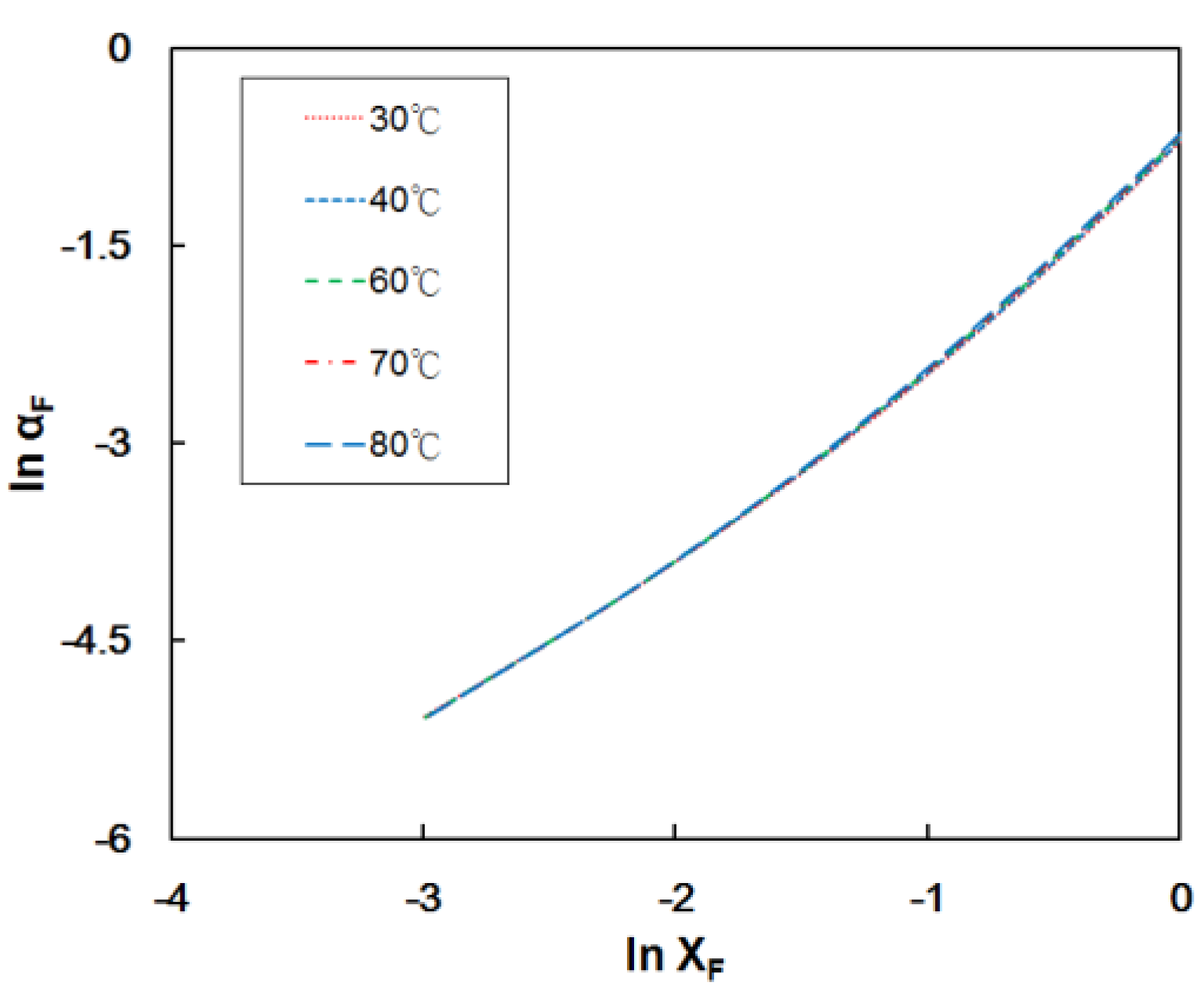
2.3. Formic Acid Diffusion Coefficient at the Anode Electrode (Dba)

The formic acid diffusion coefficient in aqueous solution was estimated using the Darken equation [31,32]:
D F W = ( D F W ° x F + D W F ° x W ) α
where DFW is the formic acid diffusion coefficient in water, D I J ° is the diffusion coefficient of the solute I in an infinitely dilute solution of solvent J, and F and W denote formic acid and water, respectively. The variables x F and x W are the formic acid and water molar fractions, respectively.
The parameter α is a thermodynamic correction term given by the following equation [33]:
α = ( ln a F ln x F ) T , P
where aF and xF are the activity and mole fraction of formic acid, respectively, in the binary formic acid/water solution. The values of D F W ° and D W F ° were predicted using the Wilke-Chang equation for the diffusion coefficients of solutes in solvents at infinite dilution [20]:
D W = 7.4 × 10 8 ( Φ F M F ) 1 / 2 T ζ F v W 0.6
and:
D F W = 7.4 × 10 8 ( Φ W M W ) 1 / 2 T ζ W v F 0.6
where T is the temperature, M is the solvent molecular weight, v is the solute molar volume at its boiling temperature, ζ is the solvent viscosity [34], and Φ is the association factor of the solvent (2.6 for water and one for formic acid [20]). The correction term α in Equation (16) was acquired from the vapor-liquid equilibrium data of formic acid and water [21] using Universal quasichemical (UNIQUAC) parameters.
By substituting appropriate formic acid concentrations and temperatures, we obtained the corresponding formic acid diffusion coefficients in water. Then, the effective formic acid diffusion coefficient in the porous diffusion layer was calculated as [22,35]:
D F W eff = ( 1 ( 3 ( 1 θ a ) 3 θ a ) ) D F W
where θa is the porosity of the anode diffusion layer. The experimental methanol diffusion coefficient at 90 °C has been reported to be 1.8 × 10⁻⁵ cm2 s−1 with a ba of 0.3 mm [18]. This value was used to calculate the apparent porosity θa (which was estimated to be 0.406). The predicted effective formic acid diffusion coefficient was used as Dba in Equations (13) and (14) to estimate the anode overpotential described in Section 2.2.

2.4. Cathode Overpotential

The cathode overpotential (ηc) caused by the diffusional mass-transfer limitation due to a loss in oxygen concentration can be predicted from the combination of the formic acid crossover, mass transport, and kinetic reaction using the following equation:
η c = b c ln ( i i e c ) b c ln ( 1 i i l c R C )
where i l c is the limiting current density at the cathode, iec is the exchange current density of the cathode, bc is the Tafel slope at the cathode, and Rc is a dimensionless parameter accounting for the potential drop due to the formic acid crossover. The bc and iec values depend on the cell temperature [36]:
b c = R T 0.7 F
and:
i e c = 0.04222 [ exp ( 73200 8.314 ) ( 1 273 + 80 1 T ) ]
This correlation depends on an activation energy of 73,200 J·mol−1, conducted between 30 and 80 °C using Nafion-117 sandwiched between Pt microelectrodes [37].
The Rc value was obtained using the following equation:
R c = i l a i l c ( μ 1 + μ ) ( 1 i i l a )
where μ is a dimensionless parameter (defined in Equation (13)), ila is the limiting current density at the anode (defined in Equation (14)), and ilc is the limiting current density at the cathode. The ilc value was obtained using the following equation:
i l c = 4 F D b c C O L b c
where Dbc is the oxygen diffusion coefficient in the cathode backing layer (detailed in the supplementary information), Lbc is the thickness of the cathode backing layer and CO is the oxygen feed concentration.
The modeling of the oxygen diffusion coefficient into the cathode is described in [6] and the details are described in the supplementary information.

3. Experimental Section

3.1. Electrolyte Preparation

The Nafion-117 membrane (from DuPont Co., Fayetteville, NC, USA) was first heated with hydrogen peroxide (5 wt. %) for 1 h to remove organic residuals and then soaked in deionized (DI) water for 30 min. Afterward, the Nafion membrane was heated in sulfuric acid (1 M) for 1 h to assemble a complete exchange to a proton-type ionic exchange membrane and again soaked with DI water. Microporous polytetrafluoroethylene (PTFE) film was immersed in a 5% silane-crosslinked sulfonated poly(styrene-ethylene/butylene-styrene) (sSEBS) solution and degassed for 15 min to allow the sSEBS solution to fill the polytetrafluoroethylene (PTFE) pores. Thus, the sSEBS matrix was reinforced by the PTFE film. The wet composite electrolyte was heated in a vacuum oven at 120 °C for 12 h and exposed to UV light (500 W) for 2 h on both sides of the PTFE to cross-linking the sSEBS. The dried sSEBS/PTFE composite was soaked in 1 M sulfuric acid at 60 °C for 1 h and soaked with DI water.

3.2. Conductivity and Formic Acid Permeability Measurements

The electrolyte membrane was immersed in DI water and formic acid solutions at different temperatures for 3 h and placed between two stainless steel electrode rods in a T-tube glass, as illustrated in our previous report [38,39,40]. The membrane was maintained at 98% relative humidity at a fixed temperature for the proton conductivity analysis. An alternate-current impedance spectrum was attained using a potentiostat (PGSTAT-30, MetrohmAutolab B.V., Utrecht, The Netherlands). Nyquist plots were employed to analyze the conductivity of the electrolytic membrane, as illustrated in our previous work [38,41].
The formic acid permeability was studied using a hand-made glass permeation cell. The permeation cell was separated into two compartments. One compartment was filled with a formic acid with DI water, and the other receiving compartment was filled with DI water. The electrolytic membrane was positioned between these two compartments, and the formic acid transport through the membrane was analyzed with time. The gas chromatograph (HP 4890A, Agilent Technologies Co. Ltd., St. Louis, MO, USA) was used to analyze the formic acid concentration. The calculations and experimental set-up of the formic acid permeability were illustrated in our previous reports [42,43].

3.3. Formic Acid Fuel Cell Test

The electrolytic membrane (Nafion-117 or sSEBS/PTFE) was sandwiched between the sheets of the gas diffusion electrodes (from E-tek, 6 mg·cm−2 Pt-Ru for the anode and 5 mg·cm−2 Pt for the cathode) to form a membrane electrode assembly (MEA). The active area of the MEA was 5 cm2. Two flow-field plates with carved double-channel serpentine flow paths (1 mm wide and 1 mm deep) were placed next to the MEA. Next to the flow-field plates, two gold-plated copper end plates were used as current collectors and assembled. For temperature control, two heating tapes were adhered to the end plate surfaces [38]. The humidified oxygen gas was fed into the cathode (flow rate of 180 mL·min−1), and the thermostated formic acid solution was fed into the anode side (flow rate of 3 mL·min−1). A thermocouple was placed into the end plates, and the analyzed temperature was fed to a controller to confirm that the cell temperature was at the set point. The electrochemical analysis of the DFAFCs were measured using a constant current density mode with a potentiostat (PGSTAT-30, MetrohmAutolab B.V., Utrecht, The Netherlands). The experimental set-up of the single cell performance was described in previous reports [38,39,44,45]. The different parameters of cell temperature ranged from 30 °C to 80 °C and a formic acid concentration from 1 M to 5 M. In the first set of experiments (1–2 M), the voltage lower limit was set at 0.45 V, but was changed to 0.1–0.2 V in subsequent experiments.

4. Results and Discussion

The thermodynamic correction term of α in Equation (16) from the Section 2.3 was acquired from the vapor–liquid equilibrium data of formic acid and water [21] using universal quasi-chemical (UNIQUAC) parameters. The values of lnaF and lnxF from 30 °C to 80 °C are plotted in Figure 1. From the slope, we obtained α values of 2.1769, 2.1743, 2.1715, and 2.1652 for 1 M, 2 M, 3 M, and 5 M formic acid solutions, respectively, at 30 °C. For instance, the α values were 1.8698, 1.8747, 1.8797, and 1.8895 for 1 M, 2 M, 3 M, and 5 M formic acid solutions, respectively, at 80 °C. The slight decreases in α values as the temperature increases are due to the methanol/water binary mixture at an elevated temperature close to an ideal solution, with the vapor-liquid equilibrium predictable using Raoult’s law [33]. Once this value was determined, the formic acid diffusivity in water was predictable for a certain composition by applying Equation (15) from Section 2.3.

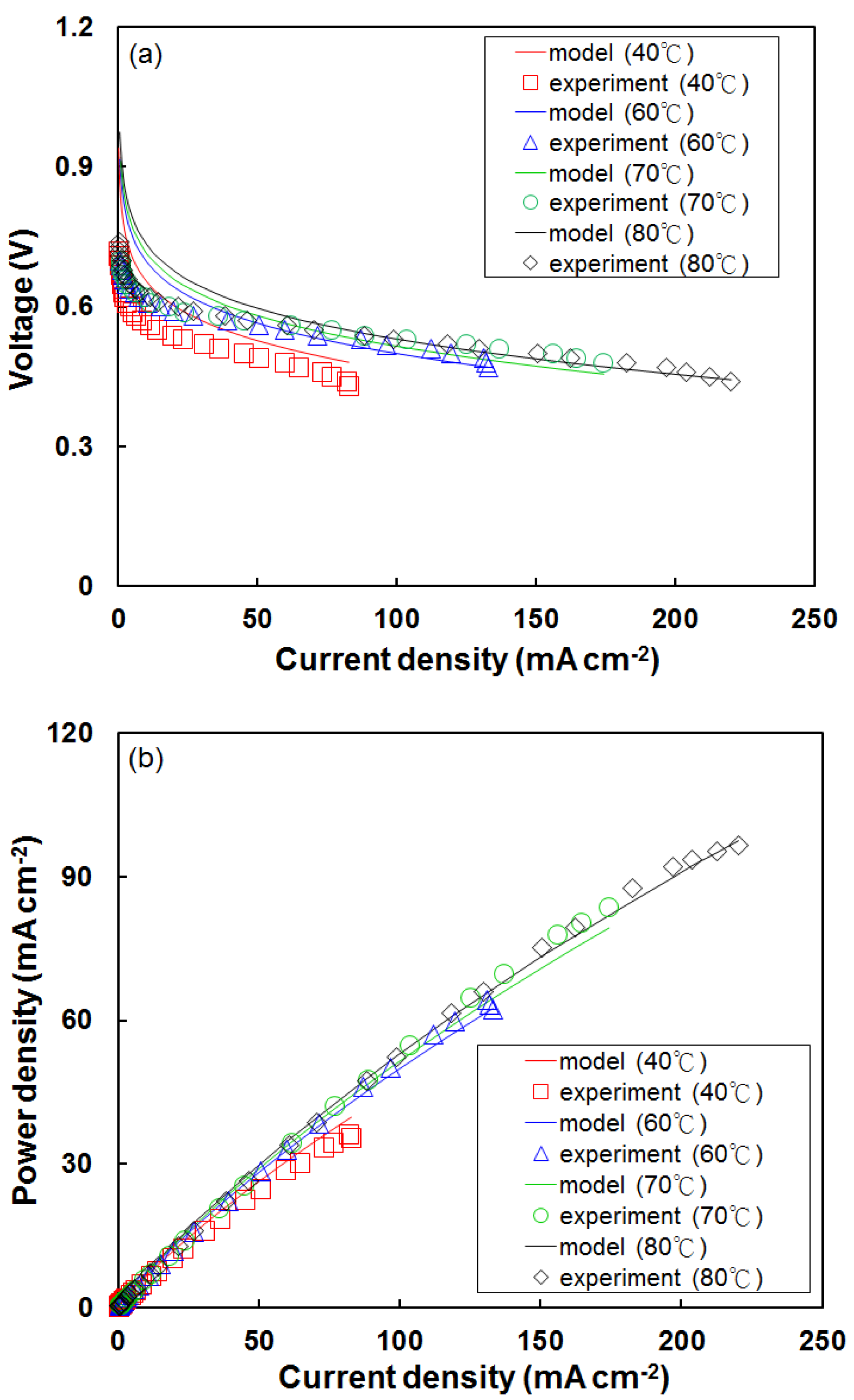
4.1. Effect of Temperature on Fuel Cell Performance Using the Modified Model

The proposed mathematical model for DFAFC performance was compared with the experimental data collected at 40 °C to 80 °C using a Nafion-117 membrane and a 1 M formic acid as the anode feed. The predicted cell voltage and current density data for the Nafion-117 membrane at 40–80 °C are shown in Figure 2a. At 40 °C, the current density of the experimental value was slightly deviated (~1%) from the theoretical modeling data. This was due to the fact that the initial electrochemical reaction between the electrodes and membrane electrolyte was not enough to transfer the protons efficiently. However, further increasing the temperature at 60 to 80 °C, the experimental current density values were exactly matched with the corresponding theoretical predication due to an improved electrochemical reaction and mass transfer phenomenon. In addition, the full cell polarization curve was obtained as a linear curve due to the reduction of the ohmic resistance and increase of the ionic conductivity. When increasing the temperature, the current density also increased from 98 to 228 mA·cm−2, respectively within the voltage range.
Similarly, the cell temperature increased from 40 °C to 80 °C, and the power density was also increased from 24.6 to 96.6 mW·cm−2. The increasing power density values resulted from the higher Nafion-117 conductivity associated with a higher temperature, leading to a slower decline in ohmic loss (Figure 2a). The result confirms that by increasing the temperature, the efficiency of the power densities was also increased due to the activation overpotential produced in the electrolyte membrane [12]. The predicted power density data using the modified model were in excellent agreement with the experimental results for the entire temperature range. One of the main contributions of this approach is the ability to predict the DFAFC performance at different temperatures, given the availability of the diffusion layer porosity data. Other determinations are based on theoretical mass-transfer equations. By assuming that the porosities are not significantly affected by the temperature change, the porosity values can be used to estimate the effective diffusivity at other temperatures using the procedure outlined in Section 2.3.

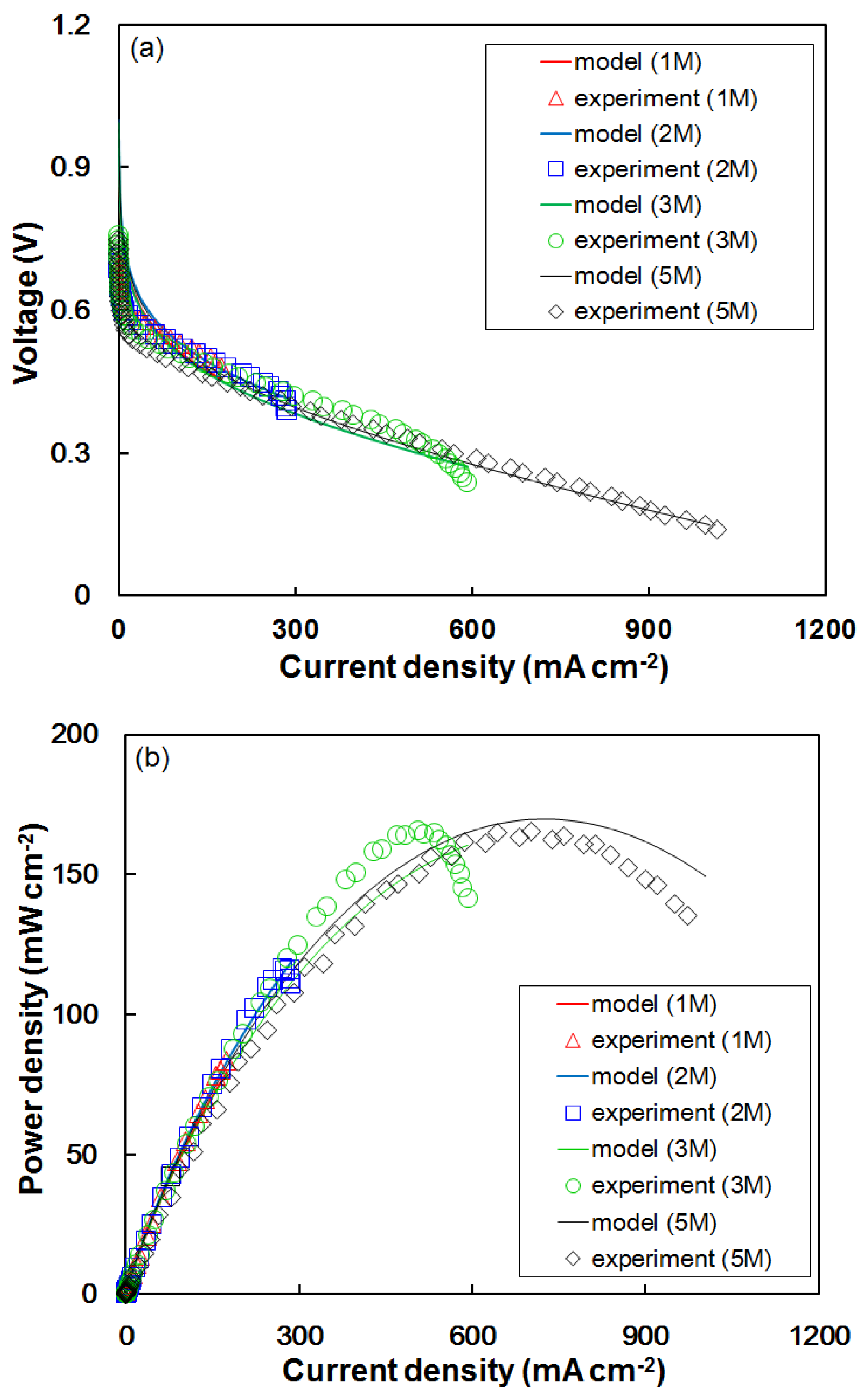
4.2. Effect of Formic Acid Concentration on Cell Performance Using the Modified Model

The estimated polarization curves and the power densities for DFAFCs fed with different formic acid feed concentrations at 70 °C and equipped with Nafion-117 membrane are illustrated in Figure 3b. The measured formic acid permeability data from the aqueous solutions of various concentrations were 7.77 × 10⁻⁶, 8.15 × 10⁻⁶, 8.52 × 10⁻⁶, and 1.25 × 10⁻⁵ cm2·s−1 for 1 M, 2 M, 3 M, and 5 M, respectively, at 70 °C. The results confirm that lower formic acid feeds suppressed the permeability than higher anode feed concentrations. The formic acid permeability has the same magnitude as the permeability of methanol in Nafion-117 [8,46]. The estimated Pmax values for 3 M, and 5 M anode feeds were 157, and 168 mW·cm−2 at 70 °C, respectively. The reason for increasing Pmax is mainly ascribed to the improved kinetics of the formic acid electro-oxidation reaction that can reduce the fuel crossover from anode to cathode at higher feed concentrations. Compared with the experimental data under similar conditions, in which the Pmax values were 150, and 176 mW·cm−2 at their corresponding formic acid concentrations, the proposed model was able to predict enhanced cell voltage and power density with increasing formic acid concentration. The theoretical and experimental deviation of Pmax values for 3 M and 4 M anode feeds were 4.5% and 4.6%, respectively. On average, the modified model predictions deviated by approximately 4.5% from the experimental data. Krishnamurthy et al. reported the computation modeling of fuel cell values have a maximum deviation of 19% when compared to experimental results with different operating parameters. The deviation occurred due to uncertainty in the kinetics and mass transfer parameters, a higher degree of anisotropy, a cross-over phenomenon and a wide range of pore sizes [10]. This model can provide reasonable DFAFC performance predictions for a wide range of formic acid concentrations. Therefore, the modified model of theoretical prediction of polarization curves and power density was more profound in the experimental analysis via anode feed concentrations.

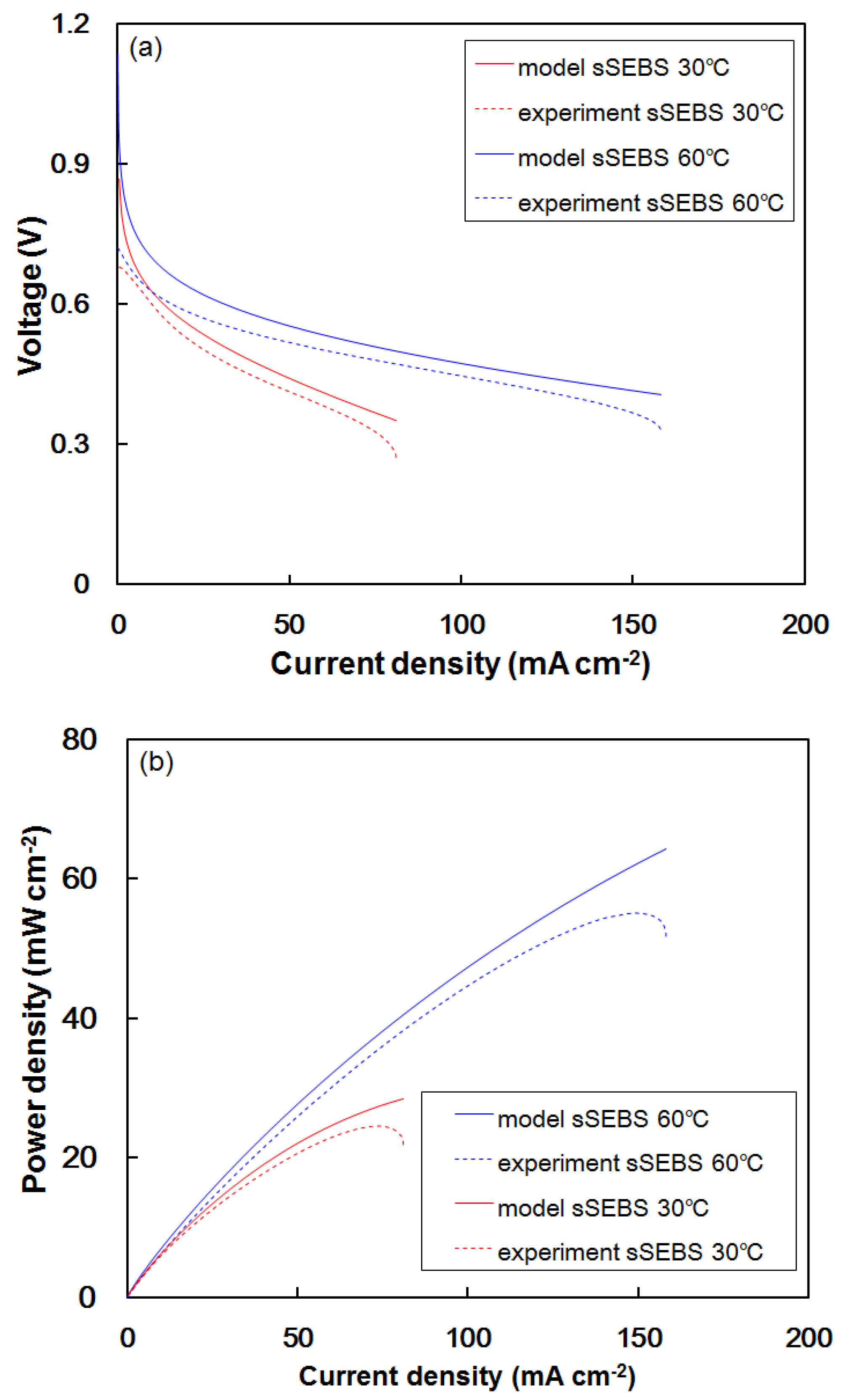
4.3. Modeling for sSEBS/PTFE Membrane Electrolytes

The DFAFC experimental results using the sSEBS/PTFE composite were used to verify the versatility of the modified model. This electrolyte membrane was fabricated and characterized in our laboratory. The estimated DFAFC voltage and power density data using the sSEBS/PTFE with 1 M formic acid feeds at 30 °C and 60 °C are shown in Figure 4a,b, respectively. The performance predictions were in accordance with the experimental data. With a 1 M formic acid feed at 30 °C, the estimated Pmax using the sSEBS/PTFE electrolyte was 28 mW·cm−2, which is approximately the experimental result of 25 mW·cm−2. For the 60 °C formic acid feed, the Pmax prediction was 63 mW·cm−2, in agreement with the experimental value of 55 mW·cm−2. The predicted peak power densities for both conditions at 30 °C and 60 °C are higher by 12–15% than the experimental results. The deviation between the experimental data and predicted values were probably due to the variation in the Tafel slope of formic acid oxidation. The literature data [47,48] were not carried out under identical conditions (such as temperature, mole concentration, etc.) and measured with acid (HCl or H2SO4) on a Pt/C catalyst. No acid was fed to the anode and Pt-Ru/C catalyst was employed in our formic acid fuel cells. These differences may contribute uncertainty to estimating the anode overpotential. We adopted the value in this work from a recently published article [29] for the simulation.
The results mentioned above demonstrate that given the electrolyte characteristics (thickness, conductivity, and formic acid permeability), operating conditions (temperature, feed concentration, electrode porosity), and associated reactant mass-transfer properties (viscosity, molar volume), one can apply our modified model to estimate the DFAFC performance. This modeling process provides cost-saving advantages by eliminating unnecessary testing of different fuel cell preparations, which would require the usage of expensive catalysts and electrolytes. Preliminary data on fuel cell performance can be simulated with sufficient precision using this model. Further work can be performed to expand the usage of this model to other operating conditions (e.g., using a Tafel slope for another catalyst) by changing appropriate variables outlined in the Section 2.

5. Conclusions

The effective diffusion coefficients of the reactants in the porous diffusion layer were estimated using the Wilke-Chang equation, the Lennard-Jones potential model, and the UNIQUAC equation for the vapor–liquid equilibrium data on formic acid/water solutions. The data were adopted into a modified Kulikovsky model to estimate the polarization curve and power density of a DFAFC. Therefore, the prediction has a theoretical basis without the requirement of any fitting parameters. The model was validated using experimental results obtained with 1 M–5 M formic acid feeds and operating temperatures at 30–80 °C with Nafion and other solid electrolytes. This model was able to predict the effects of the diffusion layer porosity, cell temperature, and formic acid concentration on cell performance using various electrolyte membranes. The simulation model provides a valuable development tool that possesses cost- and time-saving advantages for researchers. In addition, the developed theoretical modeling is valuable for both scientific thoughts and performance predictions to achieve a clear appreciation of the interplay between various physicochemical and electrochemical mechanisms for the effect on DFAFC performance.

Supplementary Materials

Supplementary materials can be accessed at: https://www.mdpi.com/1996-1073/10/12/1972/s1.

Acknowledgment

The authors acknowledge the financial support from the Ministry of Science and Technology (MOST-106-2221-E-182-051-MY3) and Chang Gung Memorial Hospital (CMRPD2F0052).

Author Contributions

Shingjiang Jessie Lue and Nai-Yuan Liu conceived and designed the experiments and theoretical analysis and the fuel cell performance; Selvaraj Rajesh Kumar and Shingjiang Jessie Lue contributes the all data analysis and wrote the paper; Kevin Chi-Yang Tseng, Bo-Yan Wang and Chieh-Hsin Leung contributed the preparation of the electrolytic membrane and data analysis. All authors examined and approved the final manuscript.

Conflicts of Interest

The authors declare no conflict of interest.

Nomenclature

aactivity of reactant or product (−)
baTafel slope at the anode (V)
bcTafel slope at the cathode (V)
COoxygen concentration (mol·cm−3)
CFformic acid concentration (mol·cm−3)
Dbaformic acid diffusion coefficient in the anode diffusion layer (cm2·s−1)
Dbcoxygen diffusion coefficient in the cathode diffusion layer (cm2·s−1)
D°solute diffusion coefficient at infinite dilution (cm2·s−1)
Deffeffective diffusion coefficient of reactant in the porous diffusion layer (cm2·s−1)
DIJdiffusion coefficient of component I in mixture with J (cm2·s−1)
E0thermodynamic cell potential at standard state (V)
Ethermodynamic cell potential at any condition (V)
FFaraday’s constant (96,485 C·mol−1)
∆G0Gibbs free energy change in overall reaction for a DFAFC at standard state (J·mol−1)
iecexchange current density for the cathode (A·cm−2)
ieaexchange current density for the anode (A·cm−2)
icurrent density (A·cm−2)
ilclimiting current density at the cathode (A·cm−2)
ilalimiting current density at the anode (A·cm−2)
Lthickness of the electrolyte (cm)
Lbcthickness of backing layer at the cathode (cm)
Lbathickness of backing layer at the anode (cm)
Mmolar mass (g·mol−1)
nnumber of electrons in half-reaction
pgas pressure (bar)
Ppower density (mW·cm−2)
Rcdimensionless parameter accounting for potential drop due to formic acid crossover (−)
Rgas constant (8.314 J·mol−1·K−1)
T*reduced temperature (−)
Ttemperature (K)
vmolar volume (cm3)
Vcell voltage (V)
xmole fraction (−)
Greek
αthermodynamic correction term (−)
βformic acid permeability (cm2·s−1)
εcharacteristic Lennard-Jones energy (J)
ζsolvent viscosity (cP)
ηΩohmic potential drop (V)
ηaoverpotential at the anode (V)
ηcoverpotential at the cathode (V)
θporosity of diffusion layer (−)
Φsolvent association constant (−)
κBoltzmann’s constant (J·K−1)
μdimensionless parameter (−)
σproton conductivity of the solid electrolyte membrane (S·m−1)
σOAcharacteristic Lennard-Jones length (Å)
ΩDdiffusion collision integral (−)

References

  1. Zhu, Y.; Ha, S.Y.; Masel, R.I. High power density direct formic acid fuel cells. J. Power Sources 2004, 130, 8–14. [Google Scholar] [CrossRef]
  2. Sebastian, D.; Serov, A.; Matanovic, I.; Artyushkova, K.; Atanassov, P.; Arico, A.; Baglio, V. Insights on the extraordinary tolerance to alcohols of Fe-NC cathode catalysts in highly performing direct alcohol fuel cells. Nano Energy 2017, 34, 195–204. [Google Scholar] [CrossRef]
  3. Mohammad, A.M.; El-Nagar, G.A.; Al-Akraa, I.M.; El-Deab, M.S.; El-Anadouli, B.E. Towards improving the catalytic activity and stability of platinum-based anodes in direct formic acid fuel cells. Int. J. Hydrog. Energy 2015, 40, 7808–7816. [Google Scholar] [CrossRef]
  4. Baik, S.; Kim, J.; Han, J.; Kwon, Y. Performance improvement in direct formic acid fuel cells (DFAFCs) using metal catalyst prepared by dual mode spraying. Int. J. Hydrog. Energy 2011, 36, 12583–12590. [Google Scholar] [CrossRef]
  5. Yu, X.; Pickup, P.G. Recent advances in direct formic acid fuel cells (DFAFC). J. Power Sources 2008, 182, 124–132. [Google Scholar] [CrossRef]
  6. Wang, B.-Y.; Lin, H.-K.; Liu, N.-Y.; Mahesh, K.; Lue, S.J. Cell performance modeling of direct methanol fuel cells using proton-exchange solid electrolytes: Effective reactant diffusion coefficients in porous diffusion layers. J. Power Sources 2013, 227, 275–283. [Google Scholar] [CrossRef]
  7. Bauskar, A.S.; Rice, C.A. Impact of anode catalyst layer porosity on the performance of a direct formic acid fuel cell. Electrochim. Acta 2012, 62, 36–41. [Google Scholar] [CrossRef]
  8. Jiang, J.; Kucernak, A. Probing anodic reaction kinetics and interfacial mass transport of a direct formic acid fuel cell using a nanostructured palladium–gold alloy microelectrode. Electrochim. Acta 2009, 54, 4545–4551. [Google Scholar] [CrossRef]
  9. Rice, C.; Ha, S.; Masel, R.; Waszczuk, P.; Wieckowski, A.; Barnard, T. Direct formic acid fuel cells. J. Power Sources 2002, 111, 83–89. [Google Scholar] [CrossRef]
  10. Krishnamurthy, D.; Johansson, E.O.; Lee, J.W.; Kjeang, E. Computational modeling of microfluidic fuel cells with flow-through porous electrodes. J. Power Sources 2011, 196, 10019–10031. [Google Scholar] [CrossRef]
  11. Perales-Rondón, J.V.; Herrero, E.; Feliu, J.M. On the activation energy of the formic acid oxidation reaction on platinum electrodes. J. Electroanal. Chem. 2015, 742, 90–96. [Google Scholar] [CrossRef] [Green Version]
  12. Reis, A.; Mert, S.O. Performance assessment of a direct formic acid fuel cell system through exergy analysis. Int. J. Hydrog. Energy 2015, 40, 12776–12783. [Google Scholar] [CrossRef]
  13. Ha, S.; Dunbar, Z.; Masel, R. Characterization of a high performing passive direct formic acid fuel cell. J. Power Sources 2006, 158, 129–136. [Google Scholar] [CrossRef]
  14. Gao, W.; Keith, J.A.; Anton, J.; Jacob, T. Theoretical elucidation of the competitive electro-oxidation mechanisms of formic acid on Pt (111). J. Am. Chem. Soc. 2010, 132, 18377–18385. [Google Scholar] [CrossRef] [PubMed]
  15. Shaegh, S.A.M.; Nguyen, N.-T.; Chan, S.H. An air-breathing microfluidic formic acid fuel cell with a porous planar anode: Experimental and numerical investigations. J. Micromech. Microeng. 2010, 20, 105008. [Google Scholar] [CrossRef]
  16. Wang, X.; Hu, J.-M.; Hsing, I.-M. Electrochemical investigation of formic acid electro-oxidation and its crossover through a Nafion® membrane. J. Electroanal. Chem. 2004, 562, 73–80. [Google Scholar] [CrossRef]
  17. Li, X.; Roberts, E.; Holmes, S. Evaluation of composite membranes for direct methanol fuel cells. J. Power Sources 2006, 154, 115–123. [Google Scholar] [CrossRef]
  18. Kulikovsky, A. A method for analysis of DMFC performance curves. Electrochem. Commun. 2003, 5, 1030–1036. [Google Scholar] [CrossRef]
  19. Hirschfelder, J.; Bird, R.B.; Curtiss, C.F. Molecular Theory of Gases and Liquids; Wiley: New York, NY, USA, 1964. [Google Scholar]
  20. Wilke, C.; Chang, P. Correlation of diffusion coefficients in dilute solutions. AIChE J. 1955, 1, 264–270. [Google Scholar] [CrossRef]
  21. Smith, J.M.; Van Ness, H.C.; Abbott, V.N. Introduction to Chemical Engineering Thermodynamics; McGraw-Hill Book: Boston, MA, USA, 2005. [Google Scholar]
  22. Das, P.K.; Li, X.; Liu, Z.-S. Effective transport coefficients in PEM fuel cell catalyst and gas diffusion layers: Beyond Bruggeman approximation. Appl. Energy 2010, 87, 2785–2796. [Google Scholar] [CrossRef]
  23. Nguyen, T.V.; White, R.E. A water and heat management model for Proton-Exchange-Membrane fuel cells. J. Electrochem. Soc. 1993, 140, 2178–2186. [Google Scholar] [CrossRef]
  24. Alberti, G.; Casciola, M. Solid state protonic conductors, present main applications and future prospects. Solid State Ion. 2001, 145, 3–16. [Google Scholar] [CrossRef]
  25. Weiss, R.; Sen, A.; Willis, C.; Pottick, L. Block copolymer ionomers: 1. Synthesis and physical properties of sulphonated poly (styrene-ethylene/butylene-styrene). Polymer 1991, 32, 1867–1874. [Google Scholar] [CrossRef]
  26. Won, J.; Choi, S.W.; Kang, Y.S.; Ha, H.Y.; Oh, I.-H.; Kim, H.S.; Kim, K.T.; Jo, W.H. Structural characterization and surface modification of sulfonated polystyrene-(ethylene-butylene)-styrene triblock proton exchange membranes. J. Membr. Sci. 2003, 214, 245–257. [Google Scholar] [CrossRef]
  27. Kim, B.; Kim, J.; Jung, B. Morphology and transport properties of protons and methanol through partially sulfonated block copolymers. J. Membr. Sci. 2005, 250, 175–182. [Google Scholar] [CrossRef]
  28. Divisek, J.; Fuhrmann, J.; Gärtner, K.; Jung, R. Performance modeling of a direct methanol fuel cell. J. Electrochem. Soc. 2003, 150, A811–A825. [Google Scholar] [CrossRef]
  29. Liu, Y.; Wang, Y.; Deng, C.; Wu, B.; Gao, Y. Kinetic study of formic acid oxidation on carbon supported platinum electrocatalyst. Electrochemistry 2010, 78, 662–665. [Google Scholar] [CrossRef]
  30. Velázquez-Palenzuela, A.; Centellas, F.; Garrido, J.A.; Arias, C.; Rodríguez, R.M.; Brillas, E.; Cabot, P.-L. Kinetic analysis of carbon monoxide and methanol oxidation on high performance carbon-supported Pt–Ru electrocatalyst for direct methanol fuel cells. J. Power Sources 2011, 196, 3503–3512. [Google Scholar] [CrossRef]
  31. Darken, L.S. Diffusion, mobility and their interrelation through free energy in binary metallic system. Trans. Am. Inst. Min. Metall. Eng. 1948, 175, 184. [Google Scholar]
  32. Ghai, R.; Ertl, H.; Dullien, F. Liquid diffusion of nonelectrolytes: Part I. AIChE J. 1973, 19, 881–900. [Google Scholar] [CrossRef]
  33. Reid, R.C.; Prausnitz, J.; Poling, B. The Properties of Gases and Liquids; McGraw-Hill: New York, NY, USA, 1987; Volume 4. [Google Scholar]
  34. Yang, C.; Wei, G.; Li, Y. Densities and Viscosities of N,N-Dimethylformamide+ Formic Acid, and+ Acetic Acid in the Temperature Range from (303.15 to 353.15) K. J. Chem. Eng. Data 2008, 53, 1211–1215. [Google Scholar] [CrossRef]
  35. Zamel, N.; Astrath, N.G.; Li, X.; Shen, J.; Zhou, J.; Astrath, F.B.; Wang, H.; Liu, Z.-S. Experimental measurements of effective diffusion coefficient of oxygen–nitrogen mixture in PEM fuel cell diffusion media. Chem. Eng. Sci. 2010, 65, 931–937. [Google Scholar] [CrossRef]
  36. Wang, Z.; Wang, C. Mathematical modeling of liquid-feed direct methanol fuel cells. J. Electrochem. Soc. 2003, 150, A508–A519. [Google Scholar] [CrossRef]
  37. Parthasarathy, A.; Srinivasan, S.; Appleby, A.J.; Martin, C.R. Temperature dependence of the electrode kinetics of oxygen reduction at the platinum/Nafion® interface—A microelectrode investigation. J. Electrochem. Soc. 1992, 139, 2530–2537. [Google Scholar] [CrossRef]
  38. Lue, S.J.; Wang, W.-T.; Mahesh, K.; Yang, C.-C. Enhanced performance of a direct methanol alkaline fuel cell (DMAFC) using a polyvinyl alcohol/fumed silica/KOH electrolyte. J. Power Sources 2010, 195, 7991–7999. [Google Scholar] [CrossRef]
  39. Rajesh Kumar, S.; Juan, C.-H.; Liao, G.-M.; Lin, J.-S.; Yang, C.-C.; Ma, W.-T.; You, J.-H.; Jessie Lue, S. Fumed silica nanoparticles incorporated in quaternized poly (vinyl alcohol) nanocomposite membrane for enhanced power densities in direct alcohol alkaline fuel cells. Energies 2016, 9, 15. [Google Scholar] [CrossRef]
  40. Lin, J.-S.; Ma, W.-T.; Shih, C.-M.; Yu, B.-C.; Teng, L.-W.; Wang, Y.-C.; Cheng, K.-W.; Chiu, F.-C.; Lue, S.J. Reorientation of magnetic graphene oxide nanosheets in crosslinked quaternized polyvinyl alcohol as effective solid electrolyte. Energies 2016, 9, 1003. [Google Scholar] [CrossRef]
  41. Rajesh Kumar, S.; Ma, W.-T.; Lu, H.-C.; Teng, L.-W.; Hsu, H.-C.; Shih, C.-M.; Yang, C.-C.; Lue, S.J. Surfactant-Assisted Perovskite Nanofillers Incorporated in Quaternized Poly (Vinyl Alcohol) Composite Membrane as an Effective Hydroxide-Conducting Electrolyte. Energies 2017, 10, 615. [Google Scholar] [CrossRef]
  42. Lue, S.J.; Juang, H.J.; Hou, S.Y. Permeation of xylene isomers through supported liquid membranes containing cyclodextrins. Sep. Sci. Technol. 2002, 37, 463–480. [Google Scholar] [CrossRef]
  43. Lue, S.J.; Shih, T.-S.; Wei, T.-C. Plasma modification on a Nafion membrane for direct methanol fuel cell applications. Korean J. Chem. Eng. 2006, 23, 441–446. [Google Scholar] [CrossRef]
  44. Lue, S.J.; Mahesh, K.; Wang, W.-T.; Chen, J.-Y.; Yang, C.-C. Permeant transport properties and cell performance of potassium hydroxide doped poly (vinyl alcohol)/fumed silica nanocomposites. J. Membr. Sci. 2011, 367, 256–264. [Google Scholar] [CrossRef]
  45. Lin, J.-S.; Kumar, S.R.; Ma, W.-T.; Shih, C.-M.; Teng, L.-W.; Yang, C.-C.; Lue, S.J. Gradiently distributed iron oxide@ graphene oxide nanofillers in quaternized polyvinyl alcohol composite to enhance alkaline fuel cell power density. J. Membr. Sci. 2017, 543, 28–39. [Google Scholar] [CrossRef]
  46. Gold, S.; Chu, K.-L.; Lu, C.; Shannon, M.A.; Masel, R.I. Acid loaded porous silicon as a proton exchange membrane for micro-fuel cells. J. Power Sources 2004, 135, 198–203. [Google Scholar] [CrossRef]
  47. Jiang, J.; Kucernak, A. Nanostructured platinum as an electrocatalyst for the electrooxidation of formic acid. J. Electroanal. Chem. 2002, 520, 64–70. [Google Scholar] [CrossRef]
  48. Lović, J.; Tripković, A.; Gojković, S.L.; Popović, K.D.; Tripković, D.; Olszewski, P.; Kowal, A. Kinetic study of formic acid oxidation on carbon-supported platinum electrocatalyst. J. Electroanal. Chem. 2005, 581, 294–302. [Google Scholar] [CrossRef]
Figure 1. Plots of lnaF versus lnxF for formic acid solutions at 30–80 °C. The slope at any formic acid mole fraction corresponds to the α value defined in Equation (16) from Section 2.3.
Energies 10 01972 g001
Figure 2. Predicted (a) polarization curves and (b) power densities for direct formic acid fuel cells (DFAFCs) at various operating temperatures, along with experimental data. The cell was fed with a 1 M formic acid solution, humidified oxygen, and equipped with a Nafion-117 electrolyte.
Energies 10 01972 g002
Figure 3. Predicted (a) polarization curves and (b) power density results for DFAFCs fed with various formic acid concentrations, along with experimental data. The DFAFCs were operated at 70 °C.
Energies 10 01972 g003
Figure 4. Predicted (a) polarization curves and (b) power density results for DFAFCs equipped with silane-crosslinked sulfonated poly(styrene-ethylene/butylene-styrene)/ porous polytetrafluoroethylene (sSEBS/PTFE) electrolyte. The DFAFCs were fed with a 1 M formic acid solution and humidified oxygen, and they were operated at 30 °C and 60 °C.
Energies 10 01972 g004

