Study of a Coil Heat Exchanger with an Ice Storage System


College of Engineering, Ocean University of China, Qingdao 266100, China
*
Author to whom correspondence should be addressed.
Energies 2017, 10(12), 1982; https://doi.org/10.3390/en10121982
Submission received: 31 October 2017
/
Revised: 23 November 2017
/
Accepted: 28 November 2017
/
Published: 1 December 2017
(This article belongs to the Special Issue Selected Papers from ICEER 2017: 2017 the 4th International Conference on Energy and Environment Research)
Abstract
:In this study, a coil heat exchanger with an ice storage system is analyzed by theoretical analysis, numerical analysis, and experimental analysis. The dynamic characteristics of ice thickness variation is studied by means of unstable heat conduction theory in cylindrical coordinates, and the change rule of the ice layer thickness is obtained. The computational fluid dynamics method is employed to simulate the flow field and ice melting process of the coil heat exchanger. The effect of the agitator height on the flow characteristics and heat transfer characteristics is investigated. The numerical results show that the turbulence intensity of the fluid near the wall of the heat exchanger is the largest with an agitator height of 80 mm. Furthermore, the process of ice melting is analyzed. The ice on the outer side of the evaporator tube close to the container wall melts faster than the inner side and this agrees well with the experimental result. The experimental study on the process of the operational period and deicing of the coil heat exchanger is conducted and the temperature variation curves are obtained by the arrangement of thermocouples. It is found that the temperature of the evaporating tube increases with increasing height in the process of ice storage.
1. Introduction
Coil heat exchangers have many advantages and superior performance, and they exist widely in many engineering fields for enhanced heat transfer. The study of coil heat exchangers is significant to the optimization of engineering problems.
In the last decade, several studies about coil heat exchangers by means of experimental study and numerical simulation have been carried out. Marija et al. [1] analyzed the performance of a helical coil heat exchanger by experiment, and the different operating conditions were discussed. Furthermore, the verification of the model was conducted. Ghorbani et al. [2] established the coiler experimental model, and the convective heat transfer of a coiler was studied. Based on the experimental data, the relationship between geometric size, operating conditions, and heat transfer performance were analyzed. Al-Hasan et al. [3] studied the coiled heat exchanger, which is embedded in a packed bed of spherical glass particles. The experiment was performed and a dimensionless correlation was proposed. In [4], the effects of the coil pitch and the curvature ratio on the pressure drop and heat transfer behavior were analyzed experimentally with the Al2O3/water nanofluid laminar flow. The authors in [5] reported the experimental results of a conical coil heat exchanger with a 90° conical coil heat exchanger, and the thermal performance was studied thoroughly. Additionally, the empirical correlations were proposed for predicting the Nusselt number. Other studies [6,7,8,9,10,11] have performed experiments and the methods for enhanced heat transfer of coils are proposed.
The numerical studies on coil heat exchangers also widely exist in various areas of the literature and they are proved to be accurate and show high performance. In [12], the authors established a model of vertical helically-coiled tubes in a cylindrical shell, the effects of the Reynolds number, coil-to-tube diameter ratios, non-dimensional coil pitches, and Rayleigh numbers on mixed convection heat transfer were numerically studied. Nada et al. [13] performed studies on a helically-coiled heat exchanger by using the FLUENT 14.5 CFD package (ANSYS, Inc., Canonsburg, PA, USA), and the characteristics of heat transfer were discussed. Additionally, the numerical results are validated by a comparison with previous experimental data. Moraveji et al. [14] carried out the investigation of a horizontal helically-coiled tube with CuO/oil-based nanofluid on the basis of the computational fluid dynamics (CFD) method. The Nusselt number was estimated by four correlations in the paper. Raju et al. [15] and Lele et al. [16] established the modelling of a helical coil heat exchanger with COMSOL software, respectively, and studied the heat transfer characteristics of the exchanger. In [17,18,19,20,21,22,23], the numerical simulations on coil heat exchangers were conducted and the optimizations of exchangers were explored.
Ice is the typical phase change material, which has many applications in the engineering field. The ice storage system has the advantages of large specific heat capacity and low cost. Yang et al. [24] studied thermal energy storage units, and the dynamic melting process of the phase change material was studied, investigated by means of experimental measurements and numerical simulations. The comprehensive solution of investigation on the heat exchange process of the thermal energy storage system using phase change material was provided. Carbonell et al. [25] established the model of an ice storage tank with heat exchangers. The investigation on main variables, such as the mass of ice and outlet temperature, were carried out, and the predictive capability of the model proved to be accurate. Zheng et al. [26] studied the charging and discharging process of an internal melt ice-on-coil thermal storage system on the basis on experiment, and the comparison between simulation and experiment was carried out.
Most of the studies have focused on the coil heat exchanger, which rarely involves the coil heat exchanger with an ice storage system. In this work, the study of a coil heat exchanger with an ice storage system is performed. We carry out three aspects of research, including theoretical analysis, numerical simulation, and experiment, to study the coil heat exchanger with an ice storage system. Moreover, this study has reference value for the enhanced heat transfer of coil heat exchangers and the application of phase change material.
2. Theoretical Analysis
2.1. Model of Ice Storage System
Water is utilized as the phase change medium in the system, which could be used for the cooling of fluid in the coil structure. The system is equipped with a stirring blade to enhance convective heat transfer. Figure 1 shows the structure of the ice storage cooling water system. These systems are mainly composed of evaporating pipe, a drinking water pipe, an agitator, and a container. There is a cold preservation layer on the surface of the container, and the surface can be regarded as the adiabatic condition.
The container is filled with medium water. The evaporating pipe, drinking water pipe, and agitator are immersed in the medium water. The evaporator pipe is externally connected to the compressor. The water in the container is frozen, and the ice is adhered to the surface of the evaporating pipe when the compressor is working. The physical parameters of the water and ice are shown in Table 1. In another circulating system, drinking water flows in the water coil, releasing heat and reducing its temperature. During the freezing process, the agitation of the blades will prevent the formation of temperature stratification, so that the thickness of the ice layer outside the evaporator tube is uniform.
2.2. Theoretical Analysis
Figure 2 shows the simplified model of the evaporation coil and its simplified model of heat transfer with phase change. The refrigerant absorbs heat in the coil shown in Figure 2a. The material of the evaporating coil pipe is copper, its external diameter is 8 mm, and there are gaps between the coils, which is favorable for preventing the ice to be completely detached away from the evaporation tube in the melting process.
Since the evaporating tube is cylinder-shaped, its physical model can be regarded as the problem of unsteady heat transfer in cylindrical coordinates. Its simplified model is shown in Figure 2b. The evaporation tube can be considered as a cylinder structure and its diameter is 50 mm. The inner diameter evaporation tube is 6 mm and its wall thickness is 0.05 mm. Thus, the outside radius of the cylinder structure (R1) is 53.5 mm. The height of evaporation coil (h) is 150 mm. The freezing process start from the position of outside radius of cylinder structure. In this section, the variation of the ice layer thickness and temperature distributions in the ice storage system are solved based on the unsteady heat transfer equation [27]. Furthermore, the purpose of this paper is to develop the practical application of ice storage based on the analytical solution. The design of exchanger includes two parts: the evaporator coil as the cold source to absorb heat in the medium water, and the drinking water coil which is also submerged in the medium water as the heat source. The drinking water in the coil can be cooled down by medium water.
The differential equation of heat conduction in the solid phase region:
The differential equation of heat conduction in the liquid phase region:
The coupling condition of temperature and heat transfer on the two-phase interface:
The temperature distribution in the solid and liquid phases are the following:
where Ei(z) is the exponential integral function.
The derivation of temperature distribution in the solid and liquid phases:
Heat absorbed from the energy-storage material:
The coupling condition of temperature on the two-phase interface can be described as follows:
This equation is valid for any moment with different τ; then:
where η is the undetermined constant. Thus, the outside ice radius is: .
The values of A and C are as follows:
The coupling condition of heat transfer on the two-phase interface can be described as follows:
The temperature of water t0 is 273.2 K.
The power of the refrigerator is 66 W and ql is obtained:
where h is the height of the evaporation coil.
Subsequently, we can obtain the value of η.
The solution of the ice thickness variation is:
It can be observed from Equation (19) that the ice thickness variation is in direct proportion to the 0.5 power of time.
3. Numerical Study
Numerical simulation is utilized to determine the agitator’s position and examine its influence on heat transfer efficiency. In our simulation, the temperature of the water in coil structure is 293.15 K, and the velocity of water in the coil structure is 0.84 m/s. The temperatures of the ice layer is 273.15 K, and the temperature of the medium water is 273.2 K. The initial thickness of the ice layer is 16 mm. The fluid is in a turbulent state and the viscosity is ignored. The heat conduction inside the wall of the drinking water pipe is set as one-dimensional heat conduction, discarding the radiation heat transfer in the system.
3.1. Numerical Method
FLUENT 16.0 CFD package (ANSYS, Inc., Canonsburg, PA, USA) is employed to perform the numerical study. The shape of the mesh is tetrahedral. Mesh independence of the numerical model has been performed and the total number of computational meshes is four million. The form of pressure-velocity coupling is SIMPLE. The turbulent kinetic energy form is second-order upwind. In detail, the solidification and melting model is used for the phase change of the coil heat exchanger with an ice storage system. The conservation equations of mass, momentum, and energy equation are as follows [28,29]:
Mass continuity equation:
Momentum conservation equation:
Energy conservation equation:
where t is the time, is the mass density, P represents the fluid pressure, is the flow velocity, e is the inside energy per unit mass, shows the volumetric force, is the thermal conductivity, is the enthalpy of species j, represents the diffusion flux of species j and, finally, exhibits the stress tensor. The rotary speed of the blade is high, the variation of the fluid velocity is frequent, and the RNG k-ε viscous model is employed to carry out the numerical simulation.
3.2. Analysis of Numerical Results
3.2.1. Effect of the Agitator Height on the Flow Field
Figure 3 shows the diagram of velocity distribution of the coil heat exchanger with different agitator heights. The height of the agitator in the system is positioned at 40 mm (Figure 3a), 60 mm (Figure 3b), 80 mm (Figure 3c), and 100 mm (Figure 3d). It can be concluded from the figure that the existence of the agitator has a significant impact on the flow field. The high rotation speed (2500 r/min) of the agitator makes the medium water in the container form a circulating flow. The medium water flows downwards from the middle of the container to the gap between the coil pipe and the bottom of the container, and then flows upward through the outer gap between the ice layer and the container, finally flowing back to the middle of the system through the top. The flow field has few vortices with the agitator height of 40 mm, and the vortex intensity increases with the increasing agitator height. For the practical application of an ice storage refrigeration system, the addition of stirring blades can increase the flow rate of the medium fluid, so that the convective heat transfer coefficient of the structure is enlarged, and the heat exchange efficiency of the system is enhanced.
3.2.2. Effect of Agitator Height on Fluid Turbulence Intensity
Figure 4 shows the effect of agitator height on fluid turbulence intensity. In this simulation, by adjusting the height of the agitator, the flow field in the system is analyzed to determine the influence of the blade position on the convective heat transfer coefficient. The average ice thickness was 3 mm, so we just set the ice as a solid part without phase change in our flow field simulation.
The cooling of drinking water is mainly caused by convective heat transfer, so the higher part of the medium water would be better cooled. At the same time, the melting of the ice provides refrigeration power, and the greater flow rate of the medium water would improve the ice melting. When the height of the blade is 80 mm, the turbulence intensity of the fluid near the wall of the heat exchanger is the largest, and the range is the widest. Based on the simulation results, the convective heat transfer coefficient is obtained, when the height of the agitator was 40, 60, 80, and 100 mm, the convective heat transfer coefficient of the drinking water pipe was 1728 W/m2·K, 2018 W/m2·K, 2543 W/m2·K, and 2104 W/m2·K, respectively. As a result, the heat transfer coefficient of the drinking water pipe wall is the highest when the blade height is 80 mm.
3.2.3. Process of Ice Melting
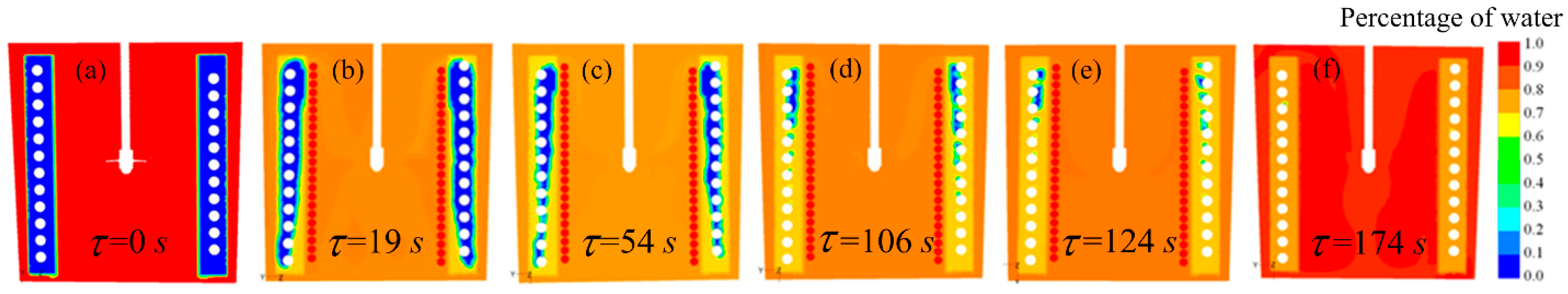
Figure 5 shows the ice melting variation chart, and the color in the picture indicates the proportion of the water. ‘Blue’ means there is 100% solid water, and ‘red’ indicates 100% liquid water. Since the simulation is mainly concerned with the melting of ice, the simulation results just shows the proportion of ice and water. As it is shown in the figure, due to the rapid flow and the large turbulence intensity of the medium water at the bottom of the container. The melting process begins from the lower part of ice layer, and the ice in the top part of coil structure finally melts. In the experimental study (Section 4), it can be observed from the temperature variation that the temperature at point 1 rises to 0 °C firstly, meaning that the melting process begins from the lower part of the layer. Thus, the numerical results agree well with the experimental results through qualitative analysis, and it follows that the numerical study is capable of simulating the melting process of the ice storage system. Combined with the velocity distribution, due to the medium water close to the container wall cycling faster, the ice here melts faster than the inside. It can be observed that while the system is working, the medium water is not 100% pure liquid water, and the medium consists of a solid-liquid mixed fluid. All of the ice finally melted at 174 s.
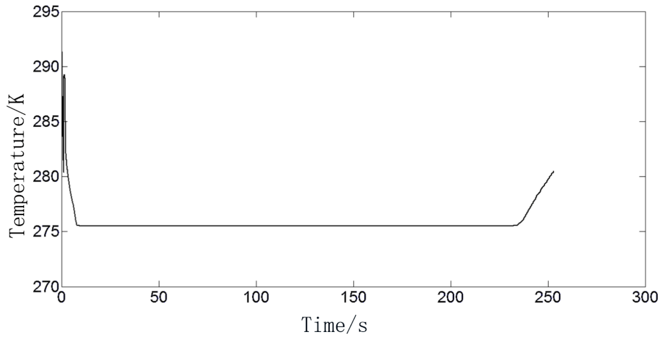
3.2.4. Outlet Temperature
The temperature variation curve of the outlet is shown in the Figure 6. As it is shown in the figure, the temperature of the outlet water has a transient fluctuation after the start-up of the system. It decreases to 2 °C quickly, then the temperature of the outlet water is steady for about four minutes. Taken together, the heat transfer effect of the coil heat exchanger with an ice-cold system has proved to be extremely powerful.
4. Experimental Study
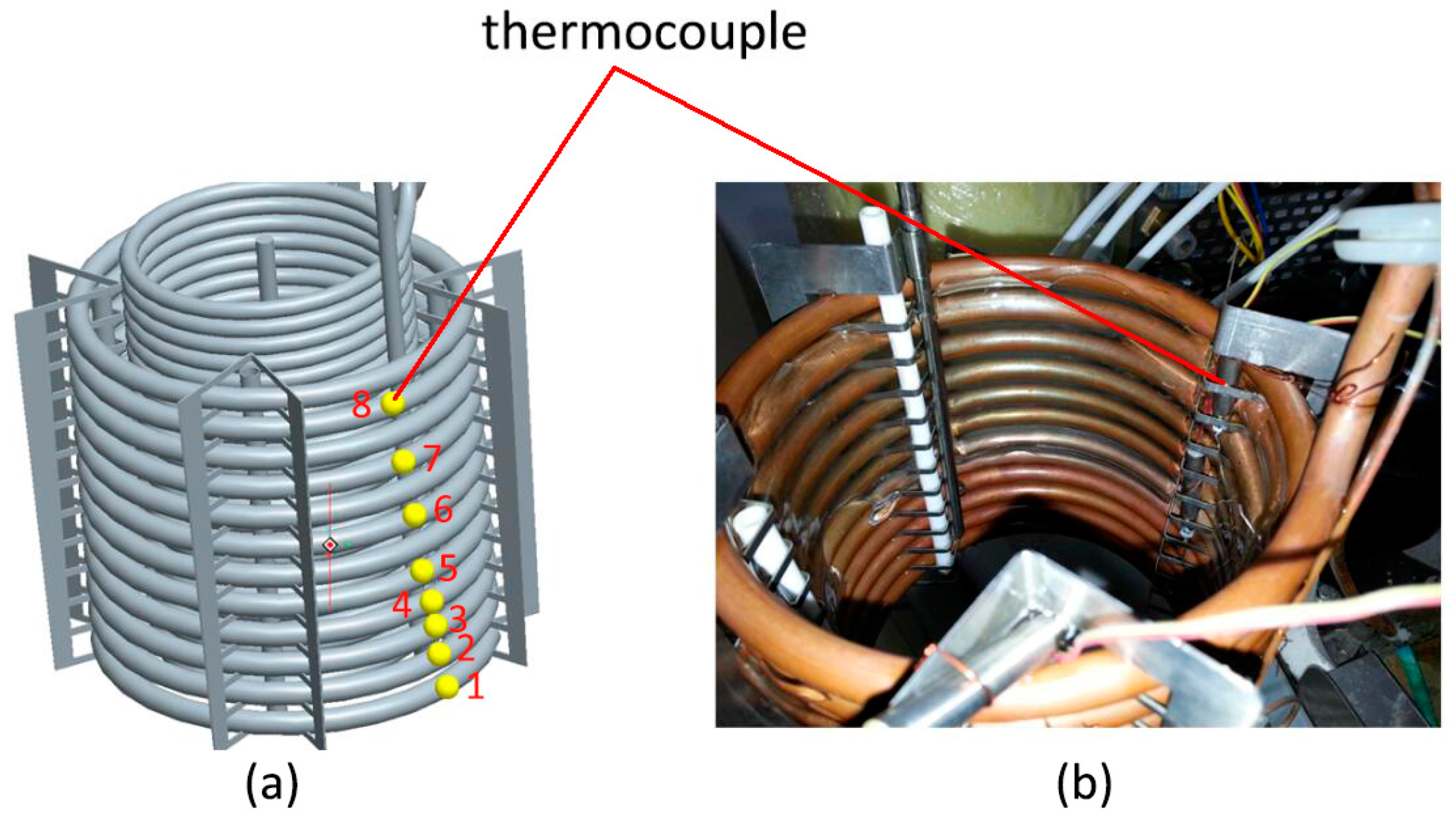
On the basis of theoretical analysis and numerical simulation, it is necessary to carry out an experiment to verify the correctness of the result. The ice storage experiment system uses the phase change of the medium water to achieve the effect of cold storage, and the system is equipped with an agitator to enhance convective heat transfer. The height of agitator is 80 mm with a rotation speed of 2500 r/min. The experimental device including self-made ice storage cycle device, T-type thermocouple and data acquisition instrument. Figure 7 shows the arrangement of the thermocouples. The measuring point of thermocouple from bottom to up is named of point 1 to point 8, respectively. Before the experiment, ice water mixture was used to calibrate the all of the T-type thermocouples, and the data acquisition instrument was used to correct the deviation.
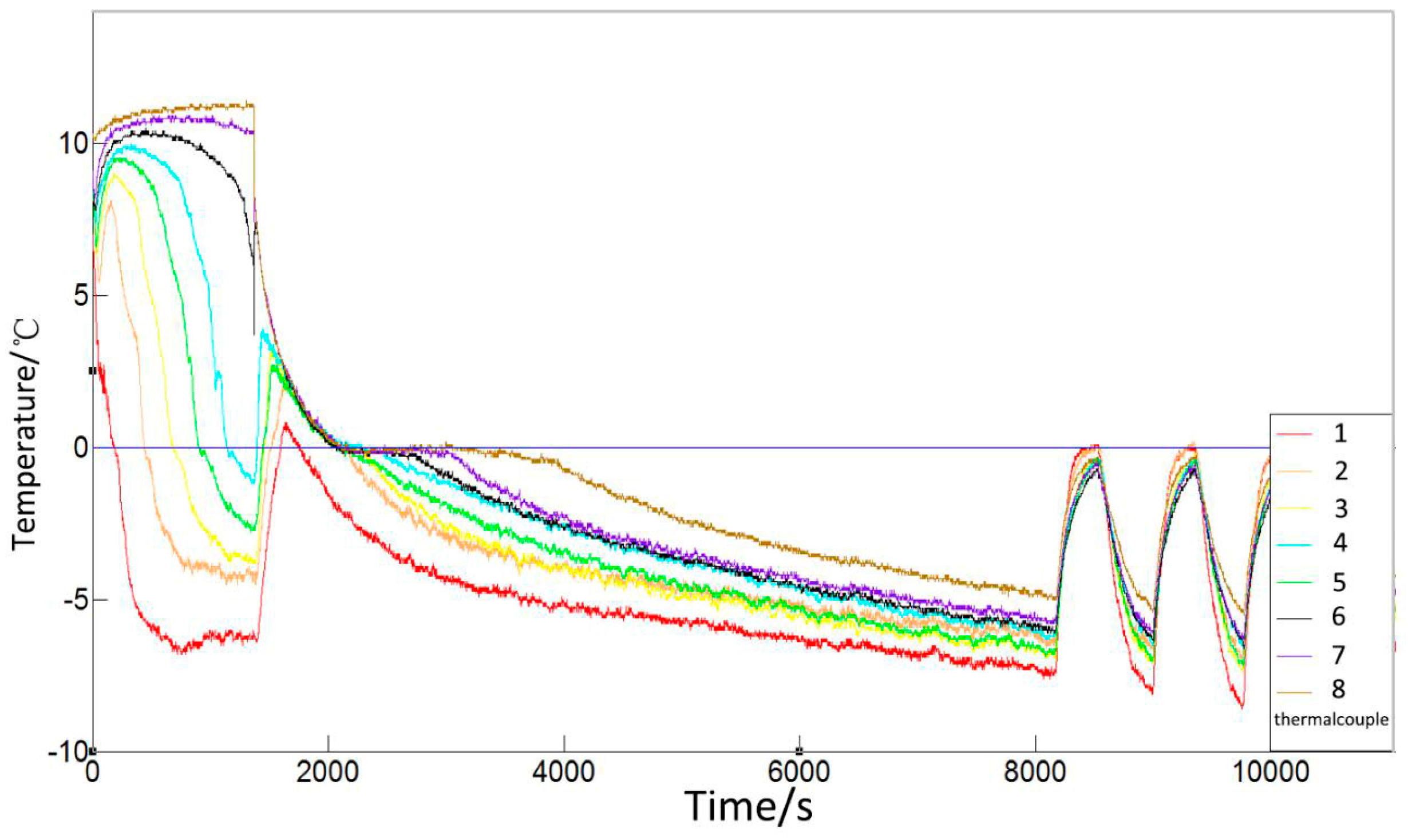
Figure 8 shows the temperature variation of evaporating tube wall during the operation period. The position of thermocouple is shown in Figure 7. The thermocouple sticks to evaporation tube. When the coil heat exchanger is in the process of ice storage, the temperature in the evaporating tube increases with increasing height. As it is shown in figure, the super-cooling degree of the medium water near the inlet of the evaporator coil (measuring point 1) is large and reaches about −7 °C. From the evaporator coil upward, the super-cooling degree of the medium water decreases in turn. The temperature of the medium water near the middle of the evaporating coil (point 6) cannot be reduced to the triple point. The large super-cooling degree of the medium water is due to the large amount of heat absorbed by the refrigerant at the inlet of the evaporator coil, so it is considered to let the refrigerant flow from top to bottom through the evaporator coil in the application of the ice storage refrigeration system. Subsequently, the compressor stops working at 1500 s, and the ice storage refrigeration system starts the process of natural deicing. Since the drinking water flows continuously and brings heat in, the temperature of the medium water at every measuring point increases rapidly, and the temperature of the ice near the upper part of the evaporator coil passes through the triple points of the water and begins to melt at first. However, the temperature of the ice at the bottom of the vessel is still below the triple point, and the temperature rising process is relatively slow. After this, the temperature of the lower part of the ice passes the triple point at 1760 s and begins to melt: at this time the temperature of the upper part of the medium water has reached the maximum temperature of 4 °C. The compressor starts working again at 1800 s, the temperature of the medium water decreases, and begins another round of the ice storage process.
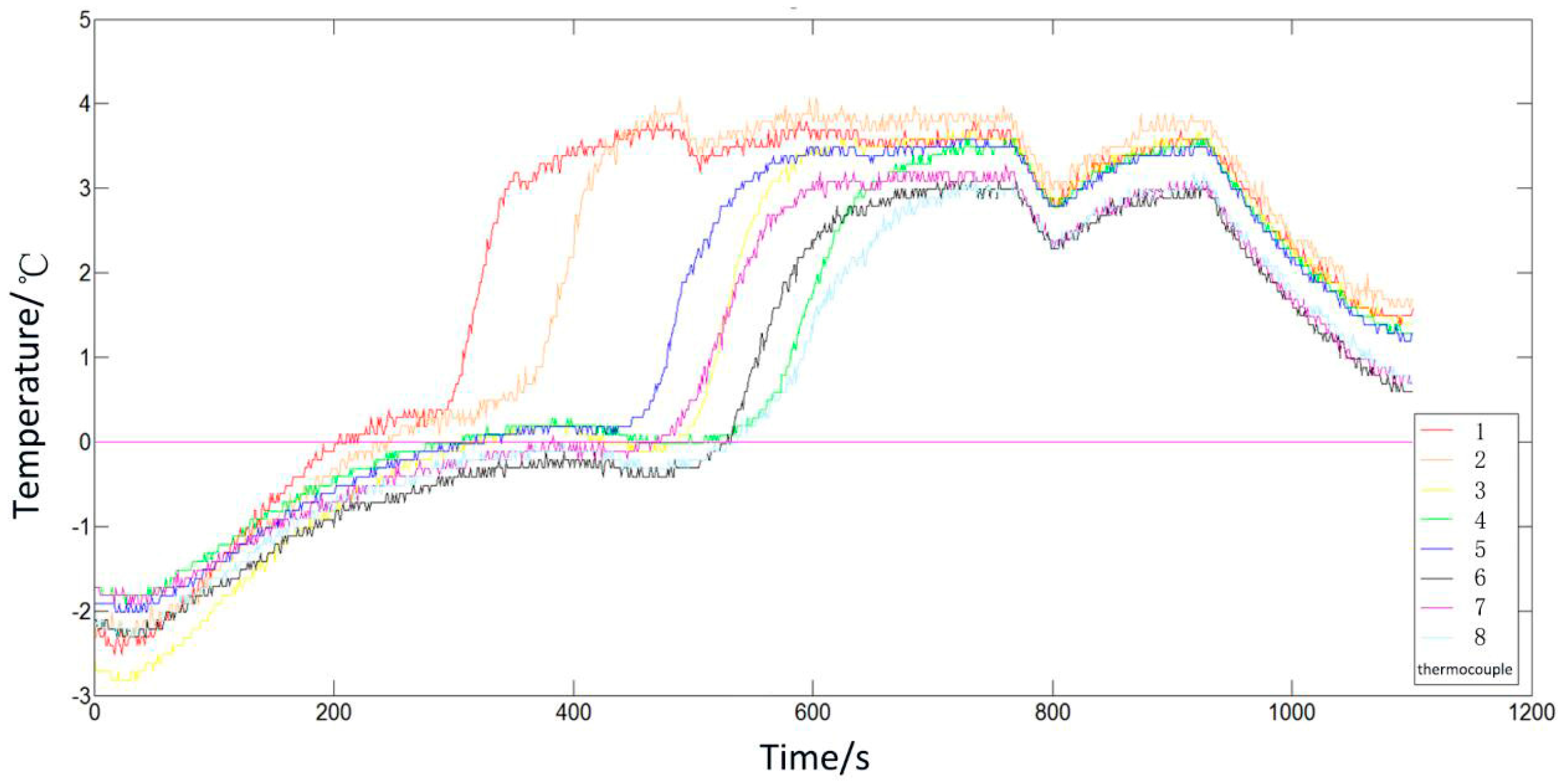
Figure 9 shows the temperature variation of the evaporating tube wall during the forced deicing period. The position of the thermocouple is shown in Figure 7 and the distance between the thermocouple and evaporation tube is 9 mm. The icing condition of the coil heat exchanger can be obtained by the temperature of the thermocouples. When the thermocouples are covered with ice, they open the outlet of the drinking water. The system continues to release ice water and the temperature variation curves of the evaporating tube wall during the forced deicing period is shown in the figure. It can be seen from the figure that the temperature of the thermocouple in the bottom position (measuring point 1) increases to 0 °C firstly, and the temperature of the thermocouples in the upper position (measuring points 6, 7, and 8) increase to 0 °C lastly. Melting occurs at the lower part of the ice layer first, and the deicing in the bottom position of the coil heat exchanger is more rapid than in the upper position. This could be explained by the analysis of flow characteristics of the medium water in the exchanger. The figure of the velocity distribution (Figure 3) shows that the medium water flows downwards from the middle of the container to the gap between the coil pipe and the bottom of the container firstly, and then flows upward through the outer gap between the ice layer and the container, finally flowing back to the middle of the system through the top. The heat transfer is in progress with the flow of the medium water. It can be concluded that the temperature of the medium water in the bottom portion of the coil structure is relatively higher through the flow characteristics of the medium water.
5. Conclusions
In this work, the study of a coil heat exchanger with an ice storage system is conducted by theoretical analysis, numerical analysis, and experimental analysis. The following conclusions can be drawn:
- The theoretical analysis of ice thickness variation in the ice storage process is performed by the unsteady heat transfer method in cylindrical coordinates, and the ice thickness variation is in direct proportion to the 0.5 power of time.
- The numerical analysis of the coil heat exchanger is investigated on the basis of the computational fluid dynamics method. The deicing in the bottom position of the coil heat exchanger is more rapid than the upper position and this agrees well with the experimental results. The turbulence intensity of the fluid near the wall of the heat exchanger is the largest with an agitator height of 80 mm, and its heat transfer coefficient of the drinking water pipe wall is the highest. Furthermore, the ice on the outer side of the evaporator tube close to the container wall melts faster than the inner side.
- The experimental analysis is performed. In the process of ice storage, the temperature of the evaporating tube increases with increasing height in the process of ice storage and the super-cooling degree of the medium water at the bottom is larger. In the process of deicing, the temperature of the thermocouple in the bottom position reaches 0 °C firstly, and melting occurs at the lower part of the ice layer.
6. Patents
Refrigerated container with ice storage system. Patent for utility model: ZL 2017 2 0146839.5, authorized by State Intellectual Property Office of the P.R.C., 2017.
Nomenclature
| ts | Temperature of solid phase |
| tl | Temperature of liquid phase |
| as | Thermal diffusivity of solid phase |
| al | Thermal diffusivity of liquid phase |
| r | Radius of ice layer |
| R1 | Radius of coil structure |
| λs | Thermal conductivity of solid phase |
| λl | Thermal conductivity of liquid phase |
| ρ | Density |
| τ | Time |
| L | Melting heat |
| A, B, C, η | Undetermined coefficient |
| E(i) | Exponential integral function |
| ql | Heat flux of hot line |
| w | Power of refrigerator |
| h | Height of evaporation coil |
| δ | Ice thickness |
| P | Fluid pressure |
| Velocity vector | |
| e | Inside energy |
| Volumetric force | |
| Enthalpy of species j | |
| Diffusion flux of species j | |
| Stress tensor |
Acknowledgments
This work is supported by the National Natural Science Foundation of China (no. 51376164), Joint Fund Project (no. 6141A02033507) and the Key Research and Development Program of Shandong Province (no. 2017GHY15113).
Author Contributions
Yan Li conceived and designed the experiments; Zhe Yan performed the theoretical analysis and wrote the paper; Chao Yang and Han Yuan analyzed the data; Bin Guo performed the experiments; Jian Zhao and Ning Mei conducted numerical simulation.
Conflicts of Interest
The authors declare no conflict of interest.
References
- Marija, L.; Alihan, K.; Marijn, B.; Steven, L.; Dimitris, M.; Michel, D.P. Experimental assessment of a helical coil heat exchanger operating at subcritical and supercritical conditions in a small-scale solar organic rankine cycle. Energies 2017, 10, 619. [Google Scholar]
- Ghorbani, N.; Taherian, H.; Gorji, M.; Mirgolbabaei, H. Experimental study of mixed convection heat transfer in vertical helically coiled tube heat exchangers. Exp. Therm. Fluid Sci. 2010, 34, 900–905. [Google Scholar] [CrossRef]
- Al-Hasan, M.; Al-Odat, M.Q.; Al-Busoul, M. An experimental investigation of forced convection heat transfer from a coiled heat exchanger embedded in a packed bed. Exp. Heat Transf. 2012, 25, 363–376. [Google Scholar] [CrossRef]
- Kahani, M.; Heris, S.Z.; Mousavi, S.M. Effects of curvature ratio and coil pitch spacing on heat transfer performance of Al2O3/water nanofluid laminar flow through helical coils. J. Dispers. Sci. Technol. 2013, 34, 1704–1712. [Google Scholar] [CrossRef]
- Purandare, P.S.; Lele, M.M.; Gupta, R.K. Experimental investigation on heat transfer analysis of conical coil heat exchanger with 90° cone angle. Heat Mass Transf. 2015, 51, 373–379. [Google Scholar] [CrossRef]
- Ghorbani, N.; Taherian, H.; Gorji, M.; Mirgolbabaei, H. An experimental study of thermal performance of shell-and-coil heat exchangers. Int. Commun. Heat Mass Transf. 2010, 37, 775–781. [Google Scholar] [CrossRef]
- Jamshidi, N.; Farhadi, M.; Ganji, D.D.; Sedighi, K. Experimental analysis of heat transfer enhancement in shell and helical tube heat exchangers. Appl. Therm. Eng. 2013, 51, 644–652. [Google Scholar] [CrossRef]
- Srisawad, K.; Wongwises, S. Heat transfer characteristics of a new helically coiled crimped spiral finned tube heat exchanger. Heat Mass Transf. 2009, 45, 381–391. [Google Scholar] [CrossRef]
- Willem, I.L.; Josua, P.M. Heat transfer during annular tube contact in a helically coiled tube-in-tube heat exchanger. Heat Transf. Eng. 2005, 26, 16–21. [Google Scholar]
- Purandare, P.S.; Lele, M.M.; Gupta, R.K. Investigation on thermal analysis of conical coil heat exchanger. Int. J. Heat. Mass Transf. 2015, 90, 1188–1196. [Google Scholar] [CrossRef]
- Andrzejczyk, R.; Muszynski, T. Thermodynamic and geometrical characteristics of mixed convection heat transfer in the shell and coil tube heat exchanger with baffles. Appl. Therm. Eng. 2017, 121, 115–125. [Google Scholar] [CrossRef]
- Mirgolbabaei, H.; Taherian, H.; Domairry, G.; Ghorbani, N. Numerical estimation of mixed convection heat transfer in vertical helically coiled tube heat exchangers. Int. J. Numer. Methods Fluids 2011, 66, 805–819. [Google Scholar] [CrossRef]
- Nada, S.A.; Elattar, H.F.; Fouda, A.; Refaey, H.A. Numerical investigation of heat transfer in annulus laminar flow of multi tubes-in-tube helical coil. Heat Mass Transf. 2017, 5, 1–12. [Google Scholar] [CrossRef]
- Moraveji, M.K.; Hejazian, M. CFD Examination of convective heat transfer and pressure drop in a horizontal helically coiled tube with CuO/oil base nanofluid. Numer. Heat Transf. A 2014, 66, 315–329. [Google Scholar] [CrossRef]
- Raju, M.; Kumar, S. Modeling of a helical coil heat exchanger for sodium alanate based on-board hydrogen storage system. In Proceedings of the COMSOL Conference, Boston, MA, USA, 7–9 October 2010. [Google Scholar]
- Lele, A.F.; Rönnebeck, T.; Rohde, C.; Schmidta, T.; Kuznik, F.; Rucka, W.K.L. Modelling of heat exchangers based on thermochemical material for solar heat storage systems. Energy Procedia 2014, 61, 2809–2813. [Google Scholar] [CrossRef]
- Vijaya, K.R.K.; Sudheer, P.K.B.; Ravi, G.; Kakaraparthi, A.; Viajaya, R.P. CFD analysis of a helically coiled tube in tube heat exchanger. Mater. Today 2017, 4, 2341–2349. [Google Scholar]
- Jayakumar, J.S.; Mahajani, S.M.; Mandal, J.C.; Iyer, K.N.; Vijayanb, P.K. CFD analysis of single-phase flows inside helically coiled tubes. Comput. Chem. Eng. 2010, 34, 430–446. [Google Scholar] [CrossRef]
- Neshat, E.; Hossainpour, S.; Bahiraee, F. Experimental and numerical study on unsteady natural convection heat transfer in helically coiled tube heat exchangers. Heat Mass Transf. 2014, 50, 877–885. [Google Scholar] [CrossRef]
- Pawar, S.S.; Sunnapwar, V.K. Experimental and CFD investigation of convective heat transfer in helically coiled tube heat exchanger. Chem. Eng. Res. Des. 2014, 92, 2294–2312. [Google Scholar] [CrossRef]
- Siriwan, N.; Chompookham, T.; Ding, Y.; Rittidech, S. Heat transfer predictions for helical oscillating heat pipe heat exchanger: Transient condition. J. Mech. Sci. Technol. 2017, 31, 3553–3562. [Google Scholar] [CrossRef]
- Yang, B.; Sekhar, S.C. Numerical algorithm studies of CFD modeling for a compartmented cooling coil under dehumidifying conditions. Numer. Heat Transf. A 2007, 52, 737–755. [Google Scholar] [CrossRef]
- Kareem, R. Optimisation of double pipe helical tube heat exchanger and its comparison with straight double tube heat exchanger. J. Inst. Eng. 2017, 98, 587–593. [Google Scholar] [CrossRef]
- Yang, X.; Xiong, T.; Dong, J.L.; Li, W.X.; Wang, Y. Investigation of the dynamic melting process in a thermal energy storage unit using a helical coil heat exchanger. Energies 2017, 10, 1129. [Google Scholar] [CrossRef]
- Carbonell, D.; Philippen, D.; Haller, M.Y.; Frank, E. Development and validation of a mathematical model for ice storages with heat exchangers that can be de-iced. Energy Procedia 2014, 57, 2342–2351. [Google Scholar] [CrossRef]
- Zheng, Z.H.; Ji, C.; Wang, W.X. Numerical simulation of internal melt ice-on-coil thermal storage system. Energy Proced. 2011, 12, 1042–1048. [Google Scholar] [CrossRef]
- Li, J.; Zhaohong, F. Advanced Heat Transfer, 2nd ed.; Higher Education Press: Beijing, China, 2008; pp. 99–101. [Google Scholar]
- Lee, D. Numerical analysis and experimental study on the performance optimization of cold storage heat exchanger integrated with evaporator. Int. J. Automot. Technol. 2017, 18, 377–385. [Google Scholar] [CrossRef]
- Sharifi, K.; Sabeti, M.; Rafiei, M.; Rafiei, M.; Mohammadi, A.H.; Shirazi, L. Computational fluid dynamics (CFD) technique to study the effects of helical wire inserts on heat transfer and pressure drop in a double pipe heat exchanger. Appl. Therm. Eng. 2017, 128, 898–910. [Google Scholar] [CrossRef]
Figure 1.
Schematic of the ice storage system: (a) graphic model of the device; and (b) simplified cross section.
Figure 1.
Schematic of the ice storage system: (a) graphic model of the device; and (b) simplified cross section.
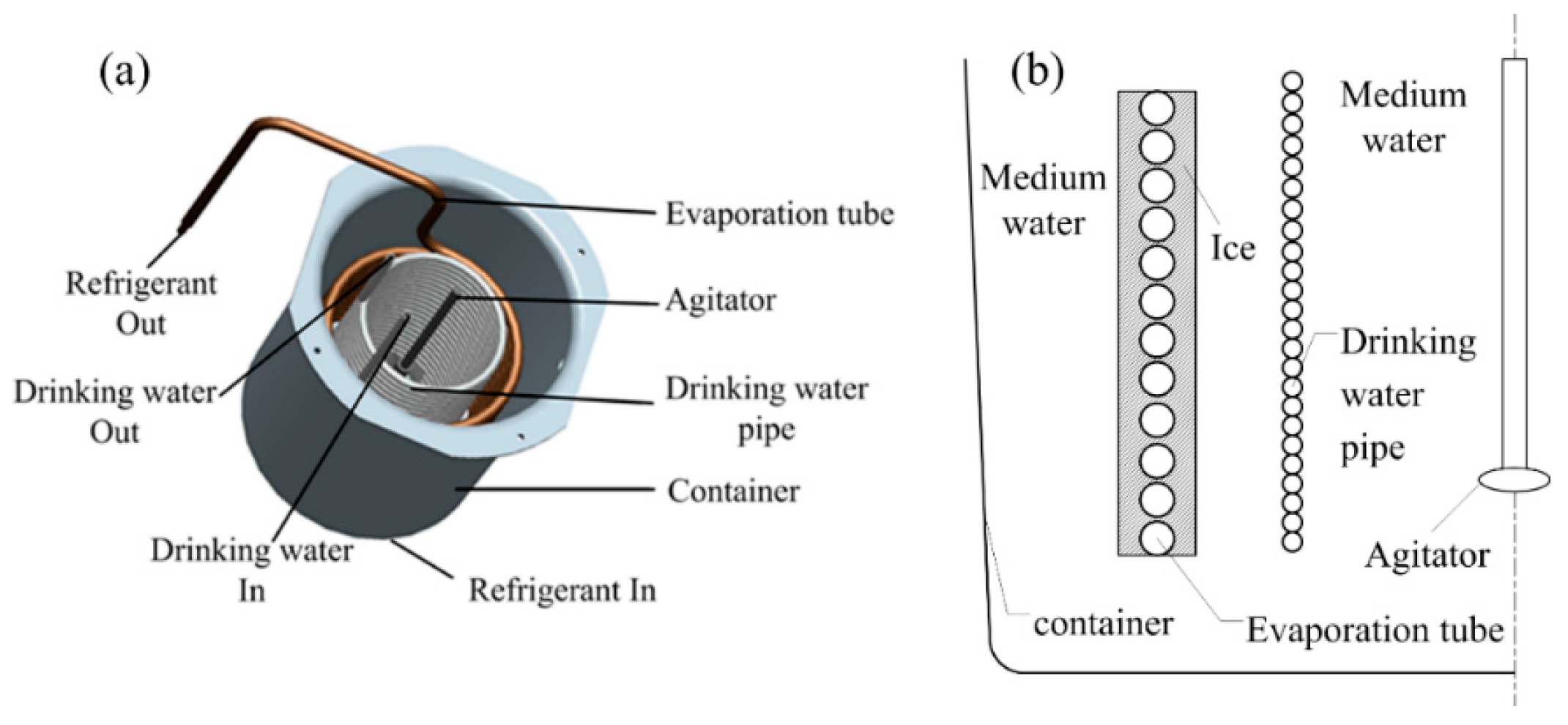
Figure 2.
Evaporation coil and its simplified model of heat transfer with phase change: (a) 2D model of the evaporation coil; and (b) unsteady heat transfer in the ice storage process.
Figure 2.
Evaporation coil and its simplified model of heat transfer with phase change: (a) 2D model of the evaporation coil; and (b) unsteady heat transfer in the ice storage process.
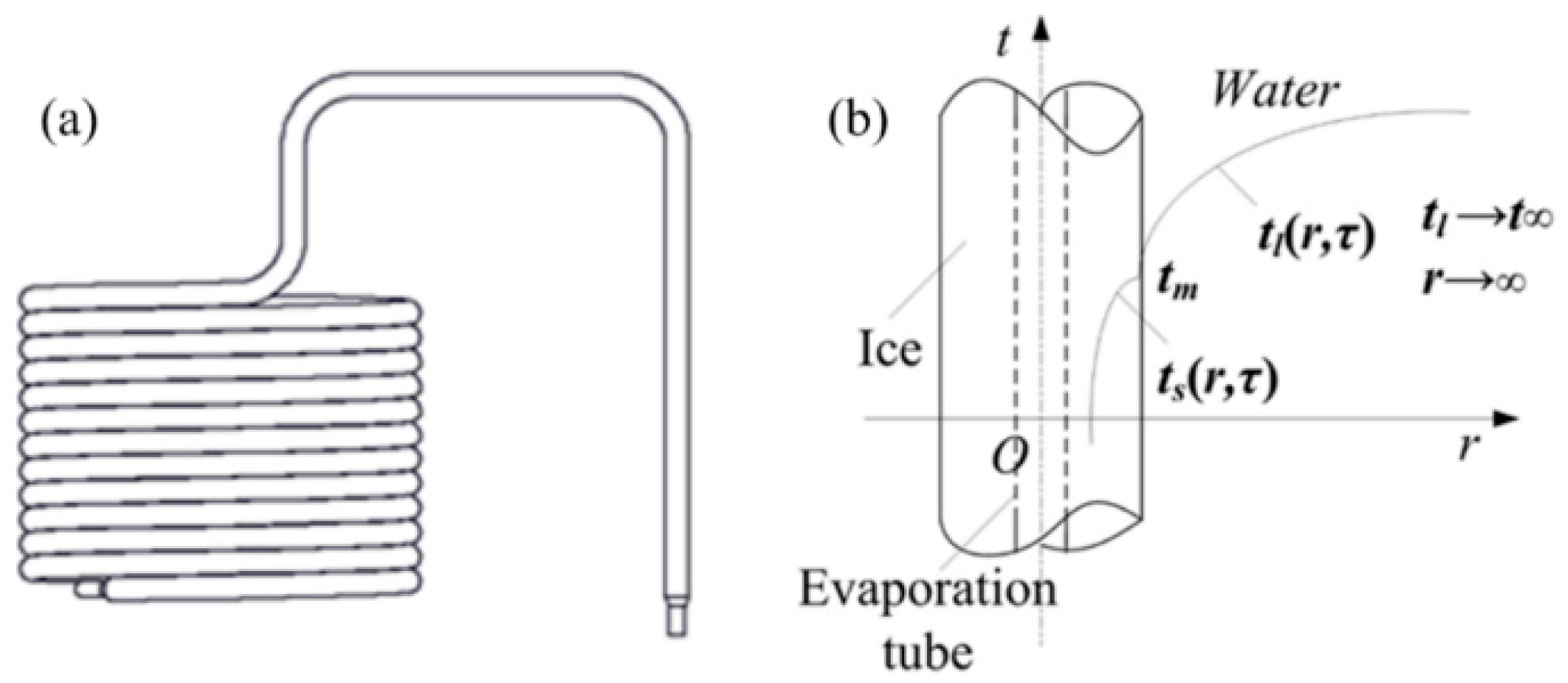
Figure 3.
Diagram of velocity distribution of the coil heat exchanger with different agitator heights. (a) h = 40 mm; (b) h = 60 mm; (c) h = 80 mm; (d) h = 100 mm.
Figure 3.
Diagram of velocity distribution of the coil heat exchanger with different agitator heights. (a) h = 40 mm; (b) h = 60 mm; (c) h = 80 mm; (d) h = 100 mm.

Figure 4.
Distribution of fluid turbulence intensity in the system. (a) h = 40 mm; (b) h = 60 mm; (c) h = 80 mm; (d) h = 100 mm.
Figure 4.
Distribution of fluid turbulence intensity in the system. (a) h = 40 mm; (b) h = 60 mm; (c) h = 80 mm; (d) h = 100 mm.
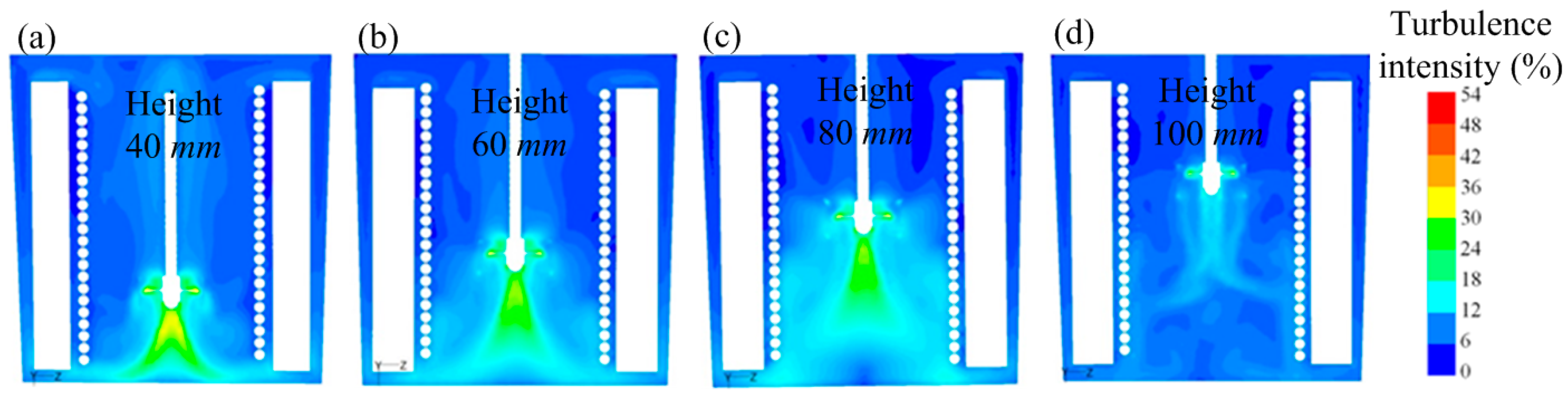
Figure 5.
Ice melting variation with time (the height of the agitator was 80 mm). (a) τ = 0 s; (b) τ = 19 s; (c) τ = 54 s; (d) τ = 106 s; (e) τ = 124 s; (f) τ = 174 s.
Figure 5.
Ice melting variation with time (the height of the agitator was 80 mm). (a) τ = 0 s; (b) τ = 19 s; (c) τ = 54 s; (d) τ = 106 s; (e) τ = 124 s; (f) τ = 174 s.

Figure 6.
Temperature variation curve of the outlet water.

Figure 7.
Arrangement of thermocouple: (a) physical model; and (b) experiment.

Figure 8.
Temperature variation of the evaporating tube wall during the operation period.

Figure 9.
Temperature variation of the evaporating tube wall during the deicing period.


Table 1.
Physical parameters of water and ice.
| Physical Parameters | Water | Ice |
|---|---|---|
| Density (kg/m3) | 999.9 | 913 |
| Specific heat capacity (J/kg·K) | 4212 | 2100 |
| Thermal conductivity (W/(m·K)) | 0.54 | 2.22 |
| Viscosity (Pa·s) | 0.0018 | - |
| Melting heat (J/kg) | 333,146 | 333,146 |
| Phase change point (K) | 273.16 | 273.16 |
© 2017 by the authors. Licensee MDPI, Basel, Switzerland. This article is an open access article distributed under the terms and conditions of the Creative Commons Attribution (CC BY) license (http://creativecommons.org/licenses/by/4.0/).
Share and Cite
MDPI and ACS Style
Li, Y.; Yan, Z.; Yang, C.; Guo, B.; Yuan, H.; Zhao, J.; Mei, N. Study of a Coil Heat Exchanger with an Ice Storage System. Energies 2017, 10, 1982. https://doi.org/10.3390/en10121982
AMA Style
Li Y, Yan Z, Yang C, Guo B, Yuan H, Zhao J, Mei N. Study of a Coil Heat Exchanger with an Ice Storage System. Energies. 2017; 10(12):1982. https://doi.org/10.3390/en10121982
Chicago/Turabian StyleLi, Yan, Zhe Yan, Chao Yang, Bin Guo, Han Yuan, Jian Zhao, and Ning Mei. 2017. "Study of a Coil Heat Exchanger with an Ice Storage System" Energies 10, no. 12: 1982. https://doi.org/10.3390/en10121982
Note that from the first issue of 2016, this journal uses article numbers instead of page numbers. See further details here.