A Three-Phase Four-Leg Inverter-Based Active Power Filter for Unbalanced Current Compensation Using a Petri Probabilistic Fuzzy Neural Network


1
Department of Electrical and Electronic Engineering, Chung Cheng Institute of Technology, National Defense University, Taoyuan City 33551, Taiwan
2
Department of Electrical Engineering, National Central University, Taoyuan City 32001, Taiwan
*
Author to whom correspondence should be addressed.
Energies 2017, 10(12), 2005; https://doi.org/10.3390/en10122005
Submission received: 20 October 2017
/
Revised: 26 November 2017
/
Accepted: 27 November 2017
/
Published: 1 December 2017
(This article belongs to the Special Issue Emerging Power Electronics Technologies for Power Systems and Machine Drives)
Abstract
:A three-phase four-leg inverter-based shunt active power filter (APF) is proposed to compensate three-phase unbalanced currents under unbalanced load conditions in grid-connected operation in this study. Since a DC-link capacitor is required on the DC side of the APF to release or absorb the instantaneous apparent power, the regulation control of the DC-link voltage of the APF is important especially under load variation. In order to improve the regulation control of the DC-link voltage of the shunt APF under variation of three-phase unbalanced load and to compensate the three-phase unbalanced currents effectively, a novel Petri probabilistic fuzzy neural network (PPFNN) controller is proposed to replace the traditional proportional-integral (PI) controller in this study. Furthermore, the network structure and online learning algorithms of the proposed PPFNN are represented in detail. Finally, the effectiveness of the three-phase four-leg inverter-based shunt APF with the proposed PPFNN controller for the regulation of the DC-link voltage and compensation of the three-phase unbalanced current has been demonstrated by some experimental results.
1. Introduction
The power pollution in power systems, which results from rectifiers, arc furnaces, nonlinear loads and switching power supplies, has been gained wide attention in recent years [1,2]. Moreover, owing to the increasing usage of power electronic equipment, the power quality in the distribution system is seriously deteriorated. Not only the voltage and current could not be operated within reasonable values, but the resulting non-sinusoidal currents could also cause voltage distortion on the load side. On the other hand, the deterioration of the power quality can be compensated effectively by using power electronic technologies [3,4]. The active power filter (APF) is one of the powerful tools used to compensate the load harmonics, unbalanced load currents and reactive power and has recently been widely adopted to improve the power quality [5,6,7]. APFs can be classified into series, shunt and hybrid APFs three categories [8,9]. A series APF is connected with the power grid in series and is effective to generate harmonic voltages to compensate load harmonic voltages [10]. Furthermore, the series APF is usually employed to protect sensitive loads in polluted grid scenarios. A series APF for the compensation of harmonics and reactive power generated by the non-linear loads was proposed in [11]. In [12], at the point of common coupling, a series APF based on a single-phase matrix converter was adopted to protect sensitive loads from the effects of voltage disturbances. However, the complexity of installation in practical applications limits the use of the series APF [13]. In addition, the hybrid APF is formed by an APF and a passive filter. In [14], a hybrid APF, which is composed of a series APF and a shunt-connected passive filter, was adopted to improve the power quality. Due to the complicated structure, the hybrid APF is still too complicated for practical applications [13]. On the other hand, a shunt APF is usually employed to compensate the harmonics introduced by non-linear loads connected to the power grid [12]. In order to compensate load harmonic currents, a shunt APF is directly connected with the power grid and loads in parallel, and is used to generate harmonic currents [10]. Owing to the simplified structure, the shunt APF has become the most widely employed type [10,15,16,17]. In [15], an adaptive hysteresis and fuzzy logic control-based three-phase four-leg interleaved buck APF was proposed to eliminate current harmonics and compensate the unbalanced load currents. In [16], a nonlinear control algorithm of the shunt APF was proposed to enhance the response for compensating the load currents. An APF using the synchronous reference frame and indirect current control strategy for improving the power quality under the unbalanced and distorted system conditions was proposed in [17]. Additionally, the power circuits for APFs can be classified into two types: voltage source converters with DC capacitor and current source converters with DC inductor [18]. Since a free-wheeling diode is connected in anti-parallel with each IGBT, the IGBT module is more suitable for the voltage source converter with DC capacitor. This means that the IGBT doesn’t need to provide the ability of reverse-blocking in itself. Hence, the IGBT possesses more flexibility for device design in a compromise among switching losses, conducting losses and short circuit ability than the reverse-blocking IGBT. On the other hand, a reverse-blocking diode is connected in series with each IGBT to construct the current source converter with DC inductor. The reverse-blocking IGBT leads to worse device characteristics and more complicated fabrication and device design than the traditional IGBT without reverse-blocking ability. Therefore, compared with the current source converter with DC inductor, the voltage source converter with DC capacitor possesses the advantages of small size, low cost, and high efficiency [18]. Moreover, since the control algorithm of the APF will cause a large amount of apparent power, which includes the active power for the losses and reactive power for the capacitor, flowing into or out of the APF, a DC-link capacitor is required on the DC side of the APF to release or absorb the apparent power [19,20]. Therefore, the regulation control of the DC-link voltage of the APF is important especially at the load variation condition. However, traditional proportional-integral (PI) controller has been adopted for the DC-link voltage regulation control only resulted in sluggish responses [19,20].
Recently, a probabilistic fuzzy neural network (PFNN) has been proposed for an induction generator system to improve its transient control performance [21]. The PFNN is composed of probabilistic neural network (PNN) and fuzzy logic. The PNN combines the feedforward neural networks and statistical pattern recognition methods to form a powerful discrimination tool [22]. Since the PNN possesses the probability density function estimator and Bayes classification rule [21], the PNN has superior modeling performance and adaptability [23]. Moreover, the fuzzy logic possesses the capabilities of fuzzy reasoning in handling uncertain information and approximating nonlinear systems [24]. Thus, many researchers have used PFNN to represent complex plants or design advanced controller [25,26]. Furthermore, the Petri net (PN) possesses analytical, graphical and mathematical modeling capabilities [27]. Hence, the PN is widely adopted to analyze the behavior of discrete event systems and is an effective tool for the verification of concurrent, parallel, distributed, asynchronous and uncertain information processing systems [28,29,30]. Owing to the above advantages of the PFNN and the PN, a Petri probabilistic fuzzy neural network (PPFNN), which integrates the advantages of PN and PFNN, is first proposed in this study to improve the transient and steady-state responses of the DC-link voltage of the shunt APF under unbalanced load change and to compensate the three-phase unbalanced currents effectively.
In this study, a three-phase four-leg inverter-based shunt APF is proposed to compensate the three-phase unbalanced currents under three-phase unbalanced load in grid-connected operation. Moreover, in order to improve the control performance of the DC-link voltage of the shunt APF under unbalanced load variation condition, an online trained PPFNN is proposed as a regulation controller to replace the traditional proportional-integral (PI) controller in the shunt APF. Furthermore, a backpropagation (BP) based online training algorithm is derived to train the connective weights and parameters of the membership functions of the proposed PPFNN online. In addition, the proposed PPFNN controller to control the DC-link voltage of the three-phase four-leg inverter-based shunt APF is implemented by a control platform using the Texas Instruments (TI) digital signal processor (DSP) TMS320F28335. The operating theories of the three-phase four-leg inverter-based shunt APF will be introduced in Section 2. The network structure, online learning algorithms and convergence analysis of the proposed PPFNN will be described in Section 3. Then, the detailed implementation of the intelligent PPFNN controlled shunt APF will be presented in Section 4. Finally, the conclusions can be found in Section 5.
2. Three-Phase Four-Leg Inverter-Based Shunt APF
The circuit scheme of the three-phase four-leg inverter-based shunt APF in grid-connected operation is shown in Figure 1. The values of the inductor Lf and capacitor Cf are 3 mH and 3 μF, respectively. The three-phase voltages vsa, vsb, vsc are 180 V and the line to line voltage of the power grid is 220 Vrms. Three resistors R1, R2, R3 are designed to be unbalanced and are connected with the power grid of a distribution system. The resulted non-sinusoidal currents could deteriorate the power quality seriously in the distribution system especially for a microgrid system operated in islanding mode [3]. Moreover, the main objective of the three-phase four-leg inverter-based shunt APF is to compensate the three-phase unbalanced currents caused by unbalanced loads R1, R2, R3. The three legs of the inverter-based shunt APF are used to generate the compensated current components and make the three-phase currents of the power grid be balanced and sinusoidal. The fourth leg is used to suppress the neutral current. The relation of the four leg currents is described as follows:
And is the neutral current of the power grid. Furthermore, the control scheme of the shunt APF is shown in Figure 2. First, the three-phase voltages of the power grid are detected to obtain the synchronous angle via the phase locked loop (PLL) unit. Then, the three-phase load currents are detected and transferred to synchronous reference frame as follows:
where iLd, iLq, and iL0 are the d, q and zero axis currents, respectively. Then, the dc components are extracted via two low pass filters which the transfer functions are designed as follows:
where the gain k = 1, damping ratio ξ = 0.7, and angular cut-off frequency ω = 20π rad/s. The dc components are subtracted by iLd, and iLq, to generate dq-axis current harmonic components and . In addition, the DC-link voltage Vdc of the shunt APF is detected and compared with the DC-link voltage command . The DC-link voltage error is then sent to a PI, PFNN or PPFNN controller, and the control current ies is produced to maintain the constant DC-link voltage Vdc of the shunt APF. The control current ies is added to the q-axis current harmonic component to obtain the q-axis current command , and name the d-axis current harmonic component and zero axis current iL0 to equal to the d-axis current command and zero axis current command , respectively. The compensated current outputs ifa, ifb, ifc of the inverter-based shunt APF are also detected and transferred to dq0 synchronous reference frame to obtain the ifd, ifq, and if0 currents, respectively. The three currents ifd, ifq, if0 are compared with the current commands , respectively and three voltage components vd, vq, v0 can be calculated by using three respective PI controller. The three control commands vcoma, vcomb, vcomc are obtained through dq0/abc coordinate transformation as follows:
The fourth control command will be computed as follows:
Finally, the pulse width modulation (PWM) switching signals are generated for maintaining the constant DC-link voltage Vdc and compensating the three-phase unbalanced currents in the three-phase four-leg inverter-based shunt APF.
3. PPFNN Controller
If the three-phase unbalanced load changes suddenly, the DC-link voltage of the shunt APF will fluctuate seriously and the compensation performance and stability of the system will be affected. Though the traditional PI control has the advantages of simple structure and easy implementation, it is not robust in dealing with the system uncertainties, which includes parameter variations, modeling errors and external disturbances, in practical applications [31]. In other words, since the traditional PI controllers are not robust in dealing with the system uncertainties, the parameters of the PI controllers are not suitable for different operating conditions. Thus, in order to improve the regulation control of the DC-link voltage of the shunt APF under unbalanced load change and to compensate the three-phase unbalanced currents effectively, the online trained PPFNN is proposed to replace traditional PI controller in the shunt APF. Since the proposed PPFNN is mainly developed based on PN, PNN and fuzzy logic control, the proposed PPFNN possesses the analytical, graphical and mathematical modeling capabilities of PN, the superior model performance and adaptability of PNN and the advantages of fuzzy logic control to handle uncertain information and to approximate nonlinear systems. Hence, the PPFNN is proposed in this study to improve the control performance of the DC-link voltage of the shunt APF. The network structure, online learning algorithms and convergence analysis of the proposed PPFNN are described as follows.
3.1. Network Structure
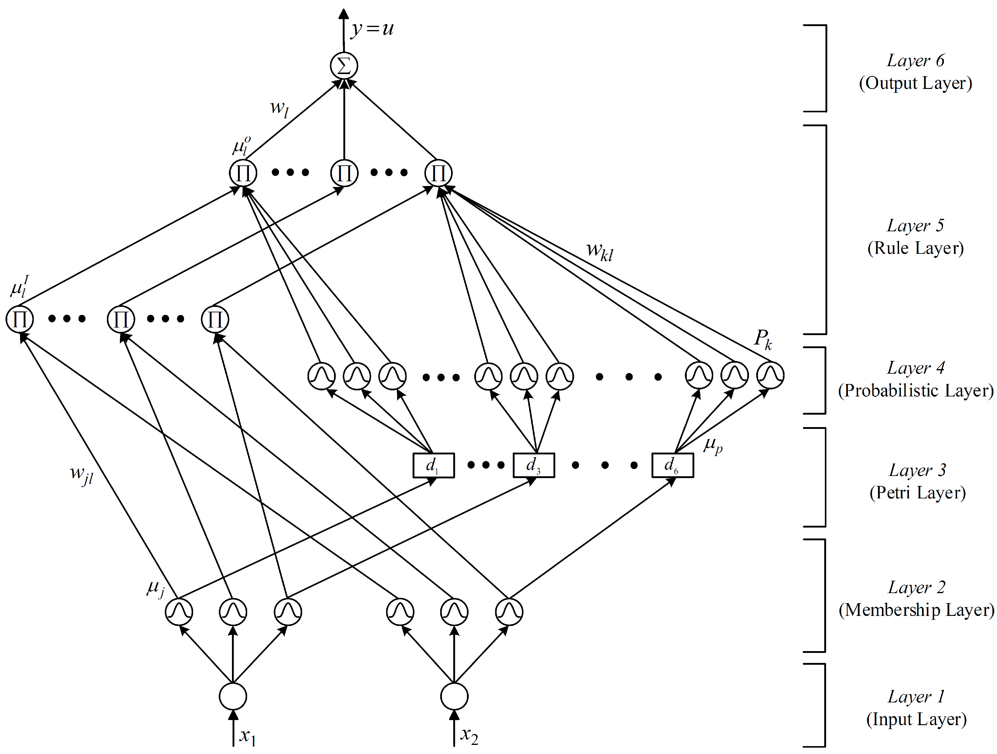
The network structure of the proposed PPFNN shown in Figure 3 has six layers including the input layer (layer 1), the membership layer (layer 2), the Petri layer (layer 3), the probabilistic layer (layer 4), the rule layer (layer 5) and the output layer (layer 6). Moreover, there are two inputs and one output. The signal propagation of each layer is described in the following:
Input layer:
The input and the output of the node in this layer are represented as:
where xn represents the nth input to the input layer; N represents the Nth iteration. In this study, the inputs of the proposed PPFNN are e1(N) = e and , which are the DC-link voltage error of the shunt APF and its derivative, respectively.
Membership layer:
The Gaussian function is adopted as the membership function in this layer, and is described in the following:
where mj and σj are the mean and standard deviation of the membership functions, respectively; μj(netj) is the output of the membership layer.
Petri layer:
In the Petri layer, the transition is in enable state when the token is produced in input place. Then, the transition is fired or unfired by the following equations [32]:
where tp is the transition; dth is threshold value and is varied by the function [32]; α and β are positive constants and set to be 0.15 and 4, respectively, by empirical rules. The token can be removed from its input place to output place when the transition is fired. That is to say, the token will stay in input place when the transition is unfired. Hence, the relationship of the input and output of the Petri layer is presented as follows:
Probabilistic layer:
The receptive field function is also a Gaussian function in the probabilistic layer, and is described as follows:
where mk and σk are the mean and standard deviation of the Gaussian function, respectively; Pk(μp) is the output of the probabilistic layer.
Rule layer:
Each node corresponds to a rule in the knowledge base in this layer. The node itself performs the t-norm operation (product operation) in the Mamdani inference to obtain the inference set according to the rules shown in (15). Moreover, the probabilistic information is processed considering the group of fuzzy grade being independent variables as shown in Equation (16) by using the Bayes’ theorem [21]. Therefore, the node input and the node output are represented as:
where and are the input of rule layer; wjl is the connective weight between the membership layer and the rule layer which is set to be 1; wkl is the connective weight between the probabilistic layer and the rule layer which is also set to be 1; is the output of the rule layer.
Layer 6 (output layer):
In output layer, the node is denoted with which performs the summation operation. Hence, the output of this layer is given as follows:
where wl is the connective weight between the rule layer and the output layer; y(N) equals the control current ies shown in Figure 2 for the regulation control of the DC-link voltage in the shunt APF.
3.2. Online Learning Algorithms
In order to describe the online learning algorithms of the proposed PPFNN, first the error function E is defined as:
The parameter learning can be achieved by the online tuning of the connective weights between the rule layer and the output layer, and the mean and standard deviation of the membership functions using the BP algorithm to minimize the error function. The online learning algorithms are described as follows:
Layer 6:
The error term to be propagated is computed as:
By using the chain rule, the connective weight wl is updated by the amount:
where η1 is the learning rate. Thus, the connective weight wl is updated as follows:
Layer 5:
The error term to be propagated is given as follows:
Layer 2:
In this layer, the error term needs to be computed and propagated as follows:
Then, by using of the chain rule, the update rules of the mean mj and standard deviation σj of the membership functions are calculated as follows:
where η2 and η3 are the learning rates of the mean and standard deviation respectively. In general, the values of the learning rates η1, η2, η3 are usually set to be between 0 and 1. By empirical rules, larger values of the learning rates η1, η2, η3 could result in divergent control responses. On the other hand, smaller values of the learning rates η1, η2, η3 could result in slow convergence of the control performance. Thus, the varied learning rates based on the analysis of a discrete-type Lyapunov function [33,34], which can guarantee the convergence of the regulation control of the DC-link voltage at a reasonable rate, are derived in this study. Then, the mean and standard deviation of the membership functions are updated as follows:
Owing to the uncertainties of the dynamic three-phase four-leg inverter-based shunt APF, the exact calculation of the Jacobian of the shunt APF, , is difficult to determine. Thus, the delta adaptation law in the following is adopted in order to increase the online learning rate of the network parameters [24]:
3.3. Convergence Analysis
In order to train the proposed PPFNN effectively, the varied learning rates [33,34] are derived in this study. The purpose of the convergence analysis is to derive specific learning rate coefficients for network parameters to assure the convergence of the intelligent regulation control of the DC-link voltage by the analysis of a discrete-type Lyapunov function.
Considering the error function in (19) as a discrete-type Lyapunov function, the variation of the Lyapunov function can be given as:
Then, the linearized model [34] of the error equation can be represented via (21), (25) and (26) by:
where Δwl, Δwj and Δσj represent the change of connect weight in the output layer, and the change of the mean and the standard deviation of the Gaussian function in the membership layer, respectively. If the learning rate parameters of the proposed PPFNN are designed as:
where ε is a positive constant, then Equation (31) can be rewritten as:
According to Equations (19) and (35), the convergence of the proposed PPFNN control can be guaranteed. Hence, the intelligent regulation control of the DC-link voltage of the shunt APF will converge to the DC-link voltage command gradually.
4. Experimental Results
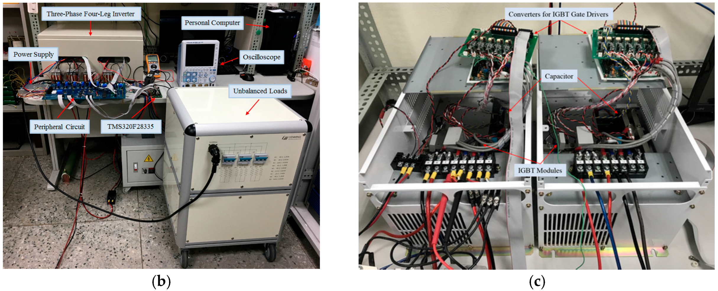
The block diagram of the three-phase four-leg inverter-based shunt APF and the photos of the experimental setups are provided in Figure 4. The block diagram of the DSP-based APF is illustrated in Figure 4a. The control algorithms, including the PLL, the unbalanced currents compensation, and the proposed PPFNN control, are implemented by the control platform using the TI DSP TMS320F28335. The peripheral circuits consist of the feedback and protect circuits. The feedback circuits are composed of two current sensors and a voltage sensor to detect the compensated current components ifa, ifb, ifc, the three-phase load currents iLa, iLb, iLc and the three-phase voltages vsa, vsb, vsc of the power grid. The over voltage/current and interlock circuits are also implemented in the control platform. Moreover, three unbalanced loads are designed as follows: (1) load 1 consists of R1 = 80 Ω, R2 = 40 Ω, R3 = 100 Ω; (2) load 2 consists of R1 = 40 Ω, R2 = 20 Ω, R3 = 60 Ω; (3) load 3 consists of R1 = 20 Ω, R2 = 10 Ω, R3 = 50 Ω. The DC-link voltage command of the shunt APF is set to be 450 V. Furthermore, the photos of the experimental setups are shown in Figure 4b. A photo of the three-phase four-leg inverter is provided as Figure 4c. In this study, two three-phase three-leg inverters are adopted to build up one three-phase four-leg inverter. In order to compare the compensation performance of the shunt APF using the proposed PPFNN controller, the experimental results using PI and PFNN controllers are also demonstrated in this study. The optimized parameters of the PI controller are obtained as Kp = 1.161, KI = 312.67 according to [35]. In addition, a three-phase unbalanced current ratio UR is defined in the following to compare the compensation performance of the shunt APF:
where Max(isa, isb, isc) is the maximum RMS current of the three-phase currents isa, isb, isc of the power grid; Min(isa, isb, isc) is the minimum RMS current of the three-phase currents isa, isb, isc; Average(isa, isb, isc) is the average RMS current of the three-phase currents isa, isb, isc. The lesser value the three-phase unbalanced current ratio UR is, the more superior compensation performance the shunt APF possesses.
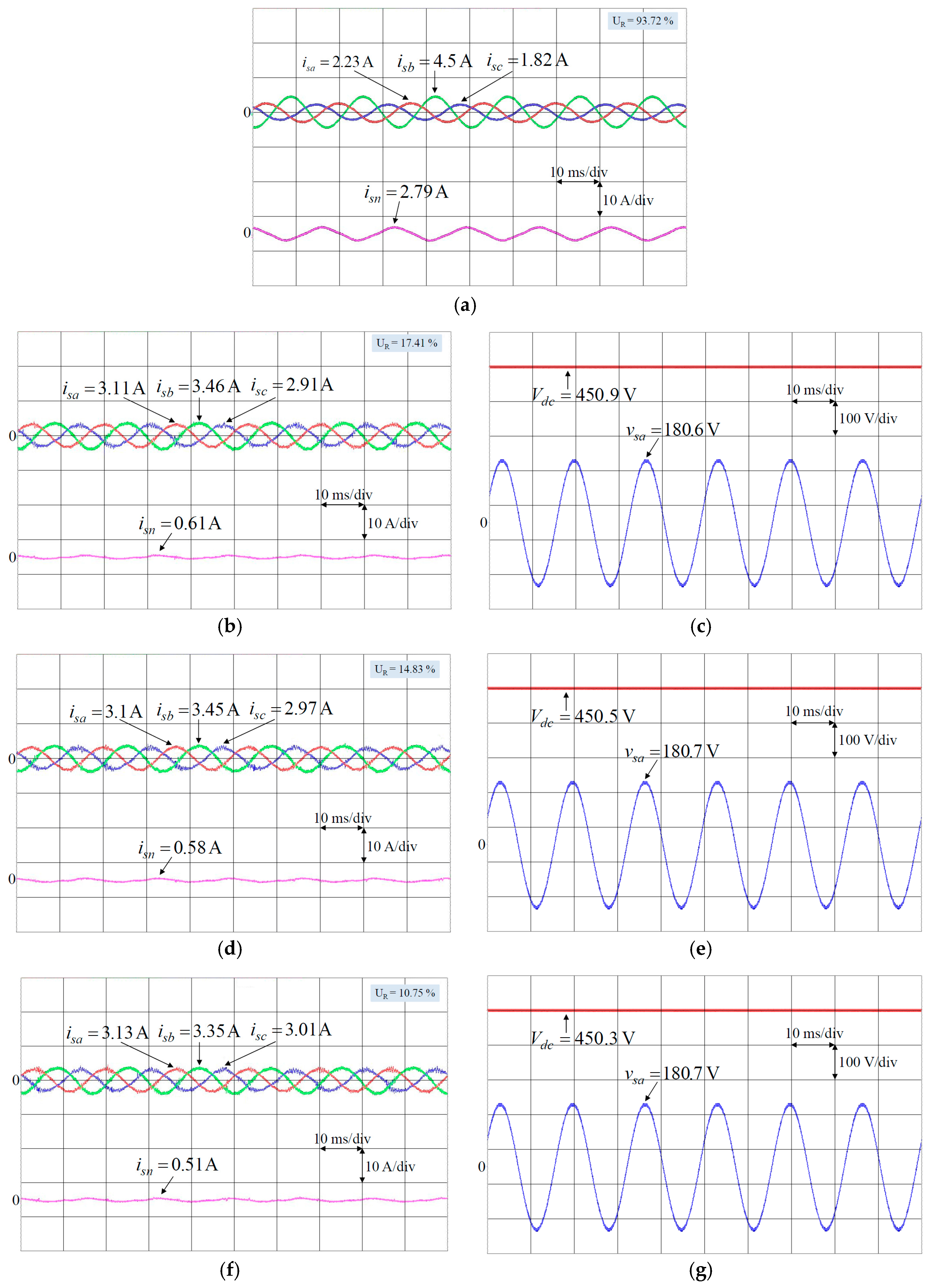
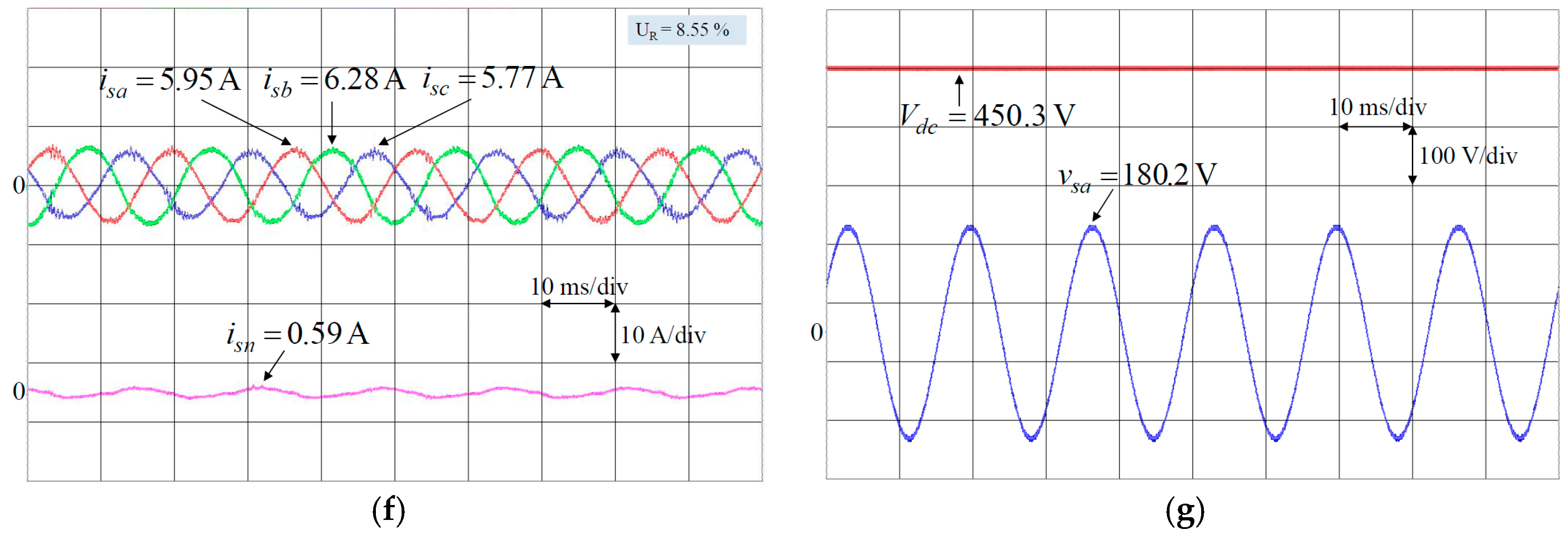
In order to verify the effectiveness of the three-phase four-leg inverter-based shunt APF under unbalanced load conditions, the experimental results without using the shunt APF and the experimental results using PI, PFNN and the proposed PPFNN controlled shunt APFs at the unbalanced load 1 are provided to demonstrate the compensation performance as shown in Figure 5. The responses of the three-phase currents isa, isb, isc and neutral current isn without using the shunt APF are shown in Figure 5a; the responses of the three-phase currents isa, isb, isc, neutral current isn, DC-link voltage Vdc and phase voltage of the power grid using PI controlled shunt APF are shown in Figure 5b,c; the responses of the three-phase currents isa, isb, isc, neutral current isn, DC-link voltage Vdc and phase voltage of the power grid using PFNN controlled shunt APF are shown in Figure 5d,e; the responses of the three-phase currents isa, isb, isc, neutral current isn, DC-link voltage Vdc and phase voltage of the power grid using the proposed PPFNN controlled shunt APF are shown in Figure 5f,g. From the experimental results shown in Figure 5a, owing to the unbalanced load 1 connected with the power grid and the absence of the shunt APF, the three-phase currents isa, isb, isc of the power grid are unbalanced with large neutral current isn. The peak value of the neutral current isn is 2.79 A. The main objective of the three-phase four-leg inverter-based shunt APF is to generate the compensated current components ifa, ifb, ifc to make the three-phase currents isa, isb, isc of the power grid be balanced, and suppress the neutral current isn. Hence, from the experimental results using PI controlled APF as shown in Figure 5b,c, the three-phase currents isa, isb, isc of the power grid can be compensated to be balanced and the peak value of the neutral current isn can be suppressed to be 0.61 A as shown in Figure 5b. The responses of DC-link voltage Vdc and phase voltage vsa of the power grid using PI controlled shunt APF are shown in Figure 5c. Moreover, from the experimental results using PFNN controlled APF as shown in Figure 5d,e, the three-phase currents isa, isb, isc of the power grid can be compensated and the peak value of the neutral current isn can be suppressed to be 0.58 A as shown in Figure 5d. The responses of DC-link voltage Vdc and phase voltage vsa of the power grid using PFNN controlled shunt APF are shown in Figure 5e. Furthermore, from the experimental results using the proposed PPFNN controlled APF as shown in Figure 5f,g. The three-phase currents isa, isb, isc of the power grid can be also compensated to be balanced and the peak value of the neutral current isn can be suppressed to be 0.51 A as shown in Figure 5f. The responses of DC-link voltage Vdc and phase voltage vsa of the power grid using the proposed PPFNN controlled shunt APF are shown in Figure 5g. In addition, the experimental results without using the shunt APF and the experimental results using PI, PFNN and the proposed PPFNN controlled shunt APFs at the unbalanced loads 2 and 3 are provided in Figure 6 and Figure 7, respectively. Additionally, the three-phase unbalanced current ratio UR without using the shunt APF and the unbalanced current ratio UR using PI, PFNN and the proposed PPFNN controlled shunt APF at the unbalanced loads 1–3 are provided in Table 1. From Table 1, since the proposed PPFNN controlled shunt APF possesses not only the abilities of the PFNN but also the analytical, graphical and mathematical modeling capabilities of PN, the three-phase unbalanced current ratio UR of the proposed PPFNN controlled shunt APF is better than PI and PFNN controlled shunt APFs.
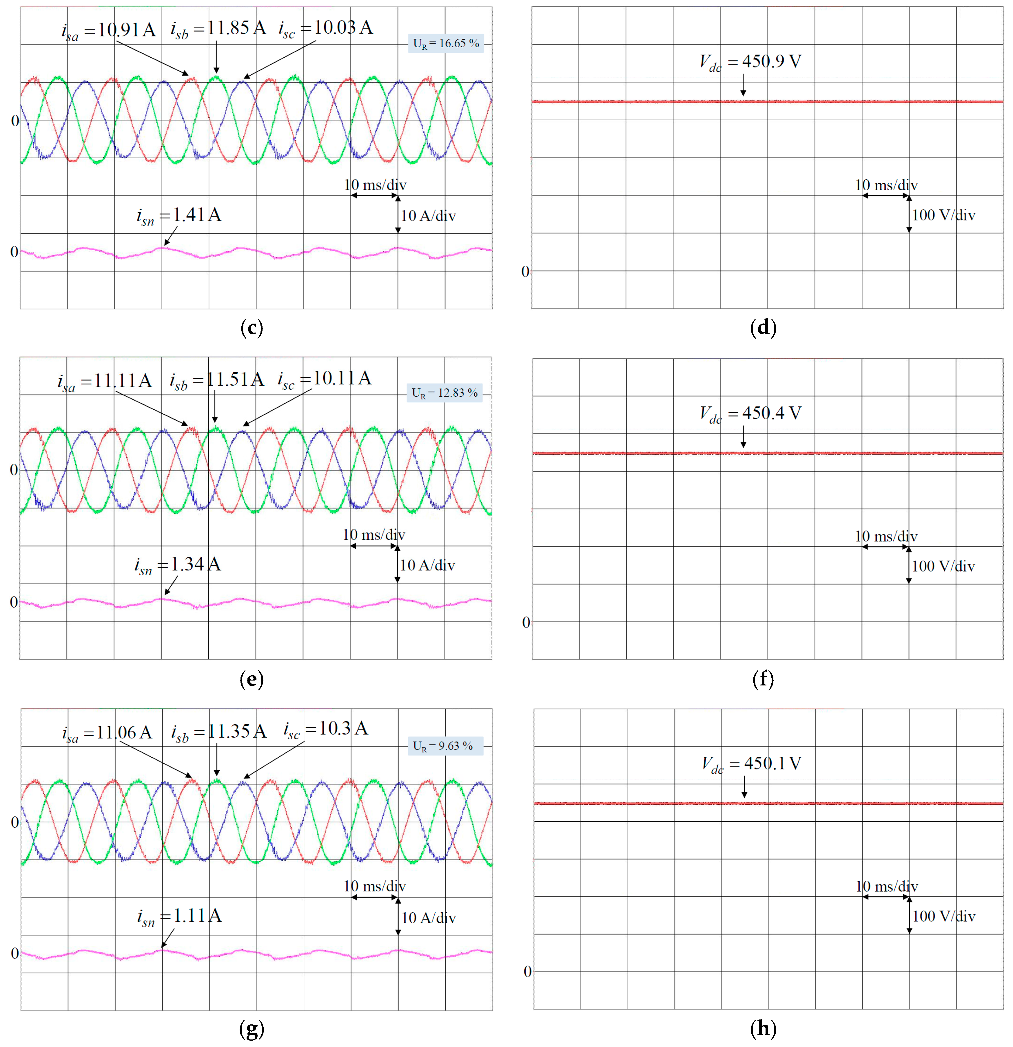
To further verify the feasibility and the effectiveness of the proposed PPFNN controlled APF with system uncertainties, a two-phase to ground fault with 0.2 per unit (pu) voltage dip on the power grid is considered at the unbalanced load 3. The experimental results without using the shunt APF and the experimental results using PI, PFNN and the proposed PPFNN controlled shunt APFs at the unbalanced load 3 under abnormal grid voltage are provided in Figure 8. First, the responses of the amplitude of grid voltage with 0.2 pu voltage dip is shown in Figure 8a. Then, the responses of three-phase currents isa, isb, isc and neutral current isn without using shunt APF are provided in Figure 8b. The three-phase unbalanced current ratio UR without using the shunt APF is 133.5% and the peak value of the neutral current isn is 9.66 A. Furthermore, the responses of the three-phase currents isa, isb, isc and neutral current isn and DC-link voltage Vdc using PI controlled shunt APF are shown in Figure 8c,d; the responses of the three-phase currents isa, isb, isc and neutral current isn and DC-link voltage Vdc using PFNN controlled shunt APF are shown in Figure 8e,f; the responses of the three-phase currents isa, isb, isc and neutral current isn and DC-link voltage Vdc using the proposed PPFNN controlled shunt APF are shown in Figure 8g,h. From the experimental results, the PI, PFNN and the proposed PPFNN controlled shunt APFs can make the three-phase currents isa, isb, isc of the power grid be balanced, and the peak value of the neutral current isn using PI, PFNN and the proposed PPFNN controlled shunt APF can be suppressed to be 1.41 A, 1.34 A and 1.11 A as shown in Figure 8c,e,g. In addition, the unbalanced current ratio UR using PI, PFNN and the proposed PPFNN controlled shunt APFs at the unbalanced load 3 under abnormal grid voltage are 16.65%, 12.83% and 9.63%, respectively. From the experimental results, though the shunt APF is operated under abnormal grid voltage, the compensation performance of the proposed PPFNN controlled shunt APF is still superior than the PI and PFNN controlled shunt APFs.
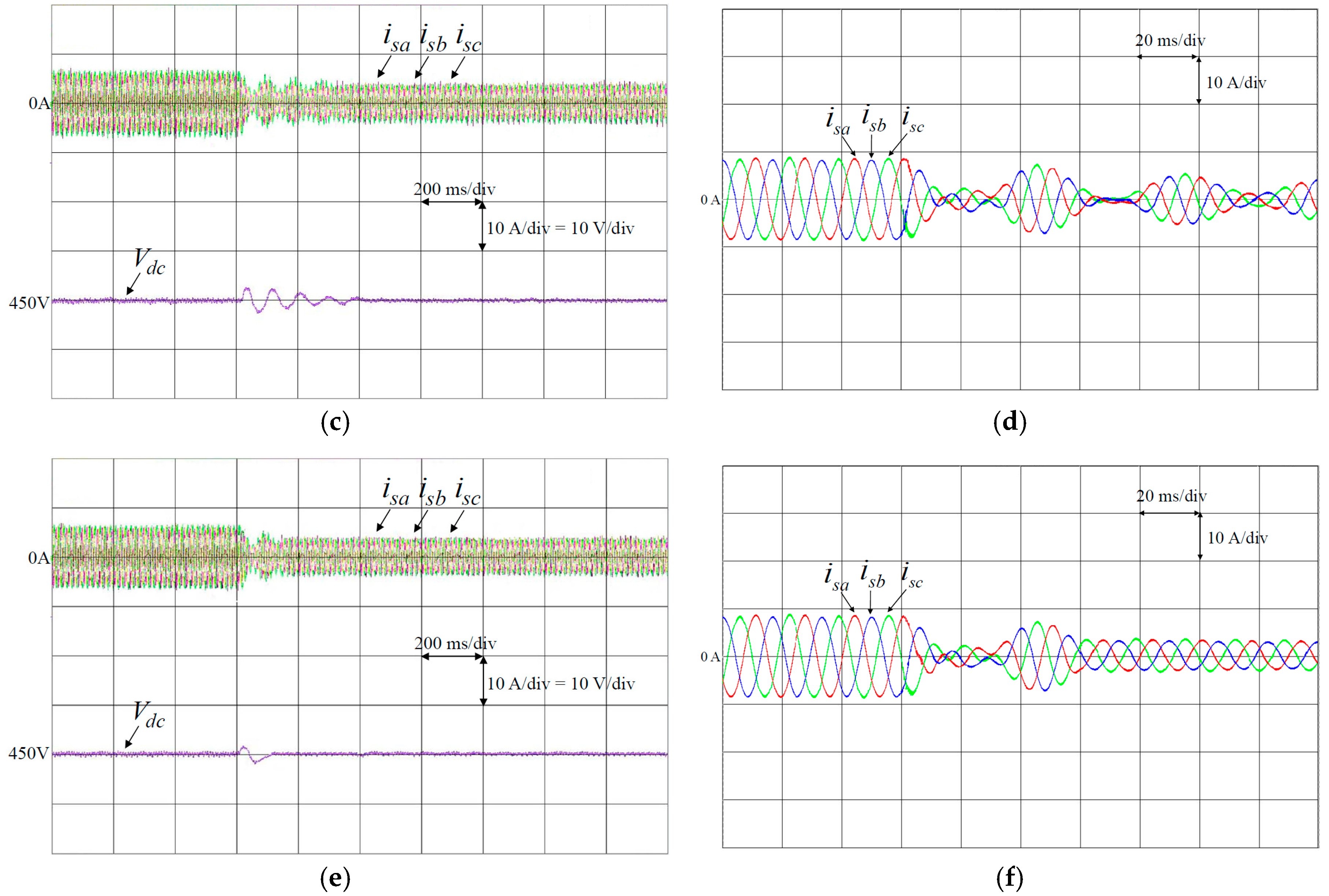
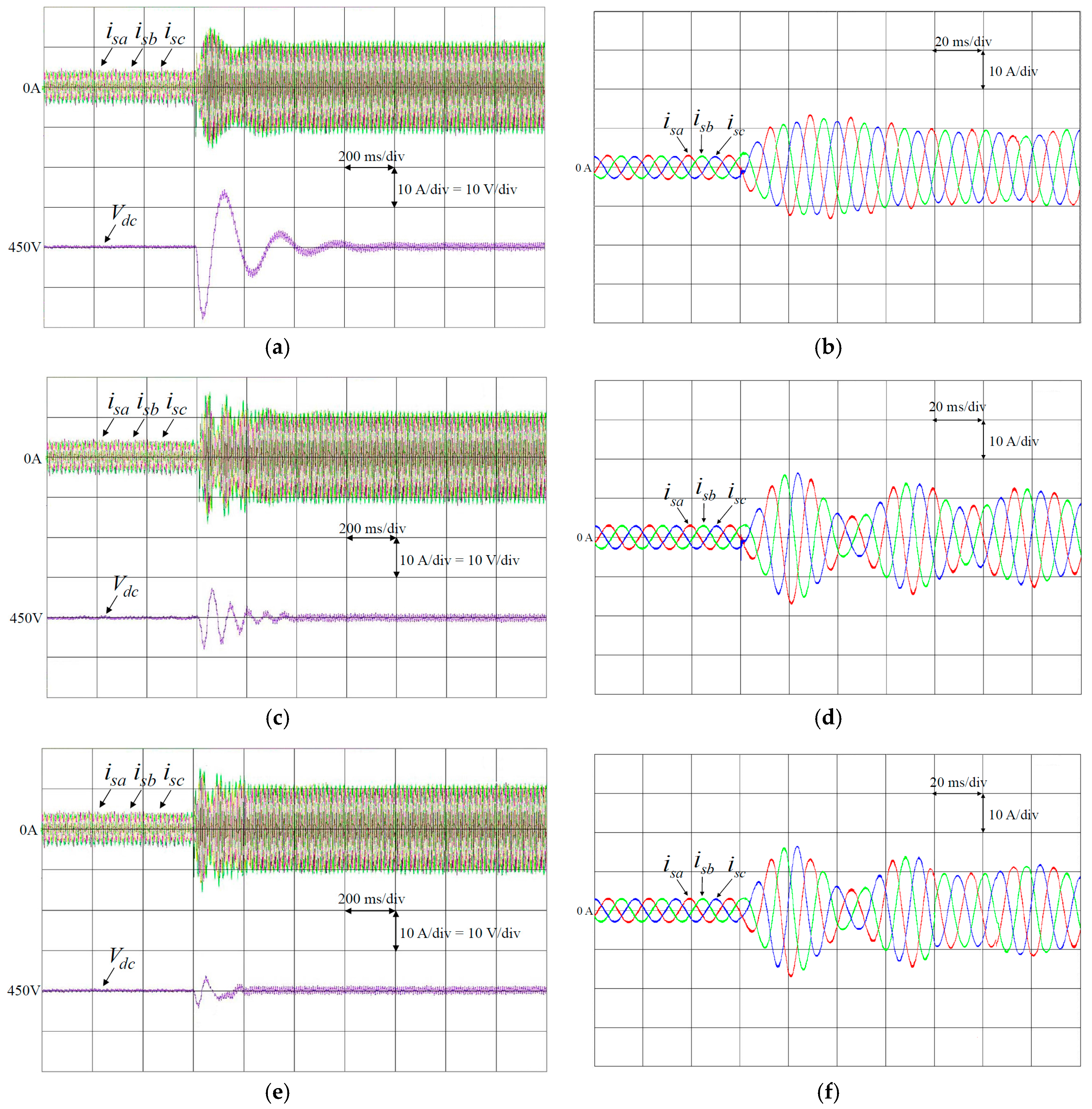
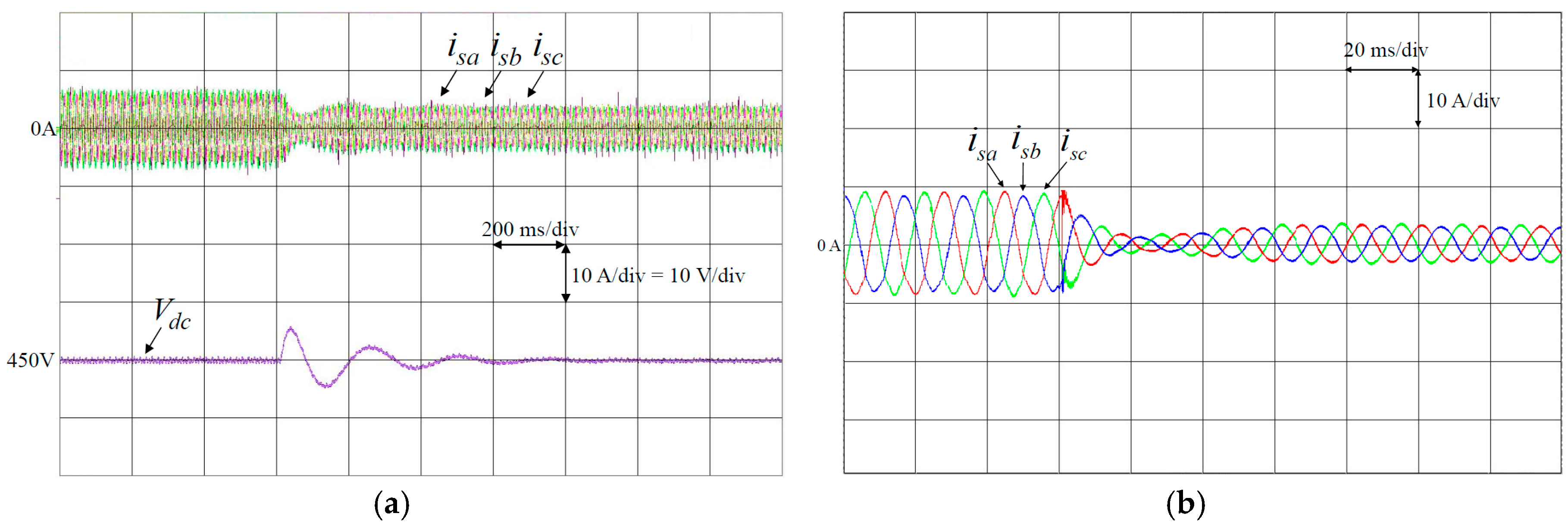
In order to verify the compensation performance and the regulation control of the DC-link voltage of the shunt APF under unbalanced load changing, two scenarios are designed as follows: (1) case 1, the load is changed from load 1 to load 3 at 0.6 s; (2) case 2, the load is changed from load 2 to load 1 at 0.6 s. First, the experimental results of PI, PFNN and the proposed PPFNN controlled shunt APF at case 1 are provided in Figure 9. The responses of the three-phase currents isa, isb, isc and DC-link voltage Vdc using PI controlled shunt APF are shown in Figure 9a. The responses of the three-phase currents isa, isb, isc using PI controlled shunt APF in 0.54–0.74 s are shown in Figure 9b. The responses of the three-phase currents isa, isb, isc and DC-link voltage Vdc using PFNN controlled shunt APF are shown in Figure 9c. The responses of the three-phase currents isa, isb, isc using PFNN controlled shunt APF in 0.54–0.74 s are shown in Figure 9d. The responses of the three-phase currents isa, isb, isc and DC-link voltage Vdc using the proposed PPFNN controlled shunt APF are shown in Figure 9e. The responses of the three-phase currents isa, isb, isc using the proposed PPFNN controlled shunt APF in 0.54–0.74 s are shown in Figure 9f. From the experimental results, the proposed PPFNN controlled shunt APF can reduce the transient and steady-state error of the DC-link voltage more rapidly as shown in Figure 9e. Comparing with PI and PFNN controllers, since the proposed PPFNN controller owns fast convergence capability with robust, the excellent regulation control of the DC-link voltage and the compensation performance can be obtained by the proposed PPFNN controlled shunt APF. Moreover, the experimental results of PI, PFNN and the proposed PPFNN controlled shunt APF at case 2 are provided in Figure 10. The responses of the three-phase currents isa, isb, isc and DC-link voltage Vdc using PI controlled shunt APF are shown in Figure 10a. The responses of the three-phase currents isa, isb, isc using PI controlled shunt APF in 0.54–0.74 s are shown in Figure 10b. The responses of the three-phase currents isa, isb, isc and DC-link voltage Vdc using PFNN controlled shunt APF are shown in Figure 10c. The responses of the three-phase currents isa, isb, isc using PFNN controlled shunt APF in 0.54–0.74 s are shown in Figure 10d. The responses of the three-phase currents isa, isb, isc and DC-link voltage Vdc using the proposed PPFNN controlled shunt APF are shown in Figure 10e. The responses of the three-phase currents isa, isb, isc using the proposed PPFNN controlled shunt APF in 0.54–0.74 s are shown in Figure 10f. From the experimental results, the transient and steady-state responses of the DC-link voltage are also much improved as shown in Figure 10e due to the powerful adaptive ability of the proposed PPFNN controlled shunt APF. Finally, a numerical performance comparison of the proposed PPFNN with PI and PFNN controllers is provided in Table 2. The response time from the transient state to steady state of the DC-link voltage and the maximum DC-link voltage error from overshoot to undershoot in transient state using PI, PFNN and the proposed PPFNN controllers at cases 1 and 2 are shown in Table 2. From Table 2, the proposed PPFNN controlled shunt APF owns fast response time and less overshoot and undershoot. Therefore, the proposed PPFNN controlled shunt APF possesses excellent compensation and regulation performance.
The execution time of the “C” program in the TMS320F28335 32-bit floating-point DSP can be obtained by the clock tool of TEXAS INSTRUMENTS Code Composer Studio (CCS) v5 program editing interface. The execution time of the shunt APF using PI, PFNN and proposed PPFNN controllers are compared in Table 3. As the result, the execution time of the shunt APF using the proposed PPFNN is still less than 1 ms which is the sampling interval of the control loop. Therefore, except the extra coding time for the shunt APF using proposed PPFNN controller, there is no extra hardware cost requirement for the implementation of the shunt APF using proposed PPFNN controller.
5. Conclusions
The development and implementation of the three-phase four-leg inverter-based shunt APF for compensating the three-phase unbalanced currents in grid-connected operation are successfully presented in this study. Moreover, if the unbalanced load changes suddenly, the DC-link voltage of the shunt APF will fluctuate seriously and the compensation performance and even the stability of the system will be affected. Hence, an online trained PPFNN controller is proposed to replace the PI and PFNN controllers to improve the control performance of the DC-link voltage of the shunt APF. Furthermore, the operating theories of the shunt APF and the network structure, online learning algorithms and convergence analysis of the proposed PPFNN have been introduced in detail. In addition, from the experimental results using the proposed PPFNN controlled shunt APF, excellent regulation control of the DC-link voltage and compensation performance can be achieved simultaneously by the proposed PPFNN controlled shunt APF due to the powerful adaptive ability of the PPFNN control. The major contributions of this study are: (i) the successful development of the three-phase four-leg inverter-based shunt APF for compensating the three-phase unbalanced currents by the control platform using the TI DSP TMS320F28335; (ii) the successful development of the proposed intelligent PPFNN control; (iii) the successful implementation of the proposed PPFNN controller for the regulation control of the DC-link voltage and the unbalanced currents compensation of the shunt APF.
Acknowledgments
The authors appreciate the financial support of the Ministry of Science and Technology, Taiwan, through its grant MOST 106-3113-F-008-002.
Author Contributions
Kuang-Hsiung Tan and Faa-Jeng Lin designed and developed the main parts of the research work, including theory derivation and analyses of the obtained results. Kuang-Hsiung Tan and Faa-Jeng Lin were also mainly responsible for preparing the paper. Jun-Hao Chen contributed in DSP-based control platform, and writing parts.
Conflicts of Interest
The authors declare no conflicts of interest.
References
- Miret, J.; de Vicuna, L.G.; Castilla, M.; Matas, J.; Guerrero, J.M. Design of an analog quasi-steady-state nonlinear current-mode controller for single-phase active power filter. IEEE Trans. Ind. Electron. 2009, 56, 4872–4881. [Google Scholar] [CrossRef] [Green Version]
- Lohia, P.; Mishra, M.K.; Karthikeyan, K.; Vasudevan, K. A minimally switched control algorithm for three-phase four-leg VSI topology to compensate unbalanced and nonlinear Load. IEEE Trans. Power Electron. 2008, 23, 1935–1944. [Google Scholar] [CrossRef]
- Garde, R.; Casado, S.; Santamaria, M.; Aguado, M. Power quality and stability analysis during islanded mode operation in a microgrid based on master-slave configuration. In Proceedings of the 2015 Saudi Arabia Smart Grid (SASG), Jeddah, Saudi Arabia, 7–9 December 2015; pp. 1–8. [Google Scholar]
- Radzi, M.A.M.; Rahim, N.A. Neural network and bandless hysteresis approach to control switched capacitor active power filter for reduction of harmonics. IEEE Trans. Ind. Electron. 2009, 56, 1477–1484. [Google Scholar] [CrossRef]
- Kedjar, B.; Al-Haddad, K. DSP-based implementation of an LQR with integral action for a three-phase three-wire shunt active power filter. IEEE Trans. Ind. Electron. 2009, 56, 2821–2828. [Google Scholar] [CrossRef]
- De, D.; Ramanarayanan, V. An active shunt compensator for reactive, unbalanced and harmonic loads under balanced and unbalanced grid voltage conditions. In Proceedings of the 2010 Joint International Conference on Power Electronics, Drives and Energy Systems & 2010 Power India, New Delhi, India, 20–23 December 2010; pp. 1–6. [Google Scholar]
- Acuña, P.; Morán, L.; Rivera, M.; Dixon, J.; Rodriguez, J. Improved active power filter performance for renewable power generation systems. IEEE Trans. Power Electron. 2014, 29, 687–694. [Google Scholar] [CrossRef]
- Pereira, R.R.; da Silva, C.H.; da Silva, L.E.B.; Lambert-Torres, G.; Pinto, J.O.P. New strategies for application of adaptive filters in active power filters. IEEE Trans. Ind. Appl. 2001, 47, 1136–1141. [Google Scholar] [CrossRef]
- Mulla, M.A.; Rajagopalan, C.; Chowdhury, A. Compensation of three-phase diode rectifier with capacitive filter working under unbalanced supply conditions using series hybrid active power filter. IET Power Electron. 2014, 7, 1566–1577. [Google Scholar] [CrossRef]
- Cirrincione, M.; Pucci, M.; Vitale, G.; Miraoui, A. Current harmonic compensation by a single-phase shunt active power filter controlled by adaptive neural filtering. IEEE Trans. Ind. Electron. 2009, 56, 3128–3143. [Google Scholar] [CrossRef]
- Kim, Y.S.; Kim, J.S.; Ko, S.H. Three-phase three-wire series active power filter, which compensates for harmonics and reactive power. IEE Proc. Electr. Power Appl. 2004, 151, 276–282. [Google Scholar] [CrossRef]
- Buticchi, G.; Barater, D.; Concari, C.; Franceschini, G. Single-phase series active power filter with transformer-coupled matrix converter. IET Power Electron. 2016, 9, 1279–1289. [Google Scholar] [CrossRef]
- Yi, H.; Zhuo, F.; Zhang, Y.; Li, Y.; Zhan, W.; Chen, W.; Liu, J. A source-current-detected shunt active power filter control scheme based on vector resonant controller. IEEE Trans. Ind. Appl. 2010, 50, 1953–1965. [Google Scholar] [CrossRef]
- Swain, S.D.; Ray, P.K.; Mohanty, K.B. Improvement of power quality using a robust hybrid series active power filter. IEEE Trans. Power Electron. 2017, 32, 3490–3498. [Google Scholar] [CrossRef]
- Panda, A.K.; Patel, R. Adaptive hysteresis and fuzzy logic controlled-based shunt active power filter resistant to shoot-through phenomenon. IET Power Electron. 2015, 8, 1963–1977. [Google Scholar] [CrossRef]
- Rahmani, S.; Mendalek, N.; Al-Haddad, K. Experimental design of a nonlinear control technique for three-phase shunt active power filter. IEEE Trans. Ind. Electron. 2010, 57, 3364–3375. [Google Scholar] [CrossRef]
- Raokhande, D.L.; Patil, D.R.; Gudaru, U. Performance of series-shunt power quality compensator under unbalanced & distorted loading conditions. In Proceedings of the IEEE International Conference on Control Applications (CCA), Hyderabad, India, 28–30 August 2013; pp. 1147–1152. [Google Scholar]
- Akagi, H. Active harmonic filters. Proc. IEEE 2005, 93, 2128–2141. [Google Scholar] [CrossRef]
- Jintakosonwit, P.; Fujita, H.; Akagi, H. Control and performance of a fully-digital-controlled shunt active filter for installation on a power distribution system. IEEE Trans. Power Electron. 2002, 17, 132–140. [Google Scholar] [CrossRef]
- Mannen, T.; Fujita, H. Dynamic control and analysis of DC-capacitor voltage fluctuations in three-phase active power filters. IEEE Trans. Power Electron. 2016, 31, 6710–6718. [Google Scholar] [CrossRef]
- Lin, F.J.; Huang, Y.S.; Tan, K.H.; Lu, Z.H.; Chang, Y.R. Intelligent-controlled doubly fed induction generator system using PFNN. Neural Comput. Appl. 2013, 22, 1695–1712. [Google Scholar] [CrossRef]
- Hart, S.J.; Shaffer, R.E.; Rose-Pehrsson, S.L.; McDonald, J.R. Using physics-based modeler outputs to train probabilistic neural networks for unexploded ordnance (UXO) classification in magnetometry surveys. IEEE Trans. Geosci. Remote Sens. 2001, 39, 797–804. [Google Scholar] [CrossRef]
- Jin, X.; Srinivasan, D.; Cheu, R.L. Classification of freeway traffic patterns for incident detection using constructive probabilistic neural networks. IEEE Trans. Neural Netw. 2001, 12, 1173–1187. [Google Scholar] [CrossRef] [PubMed]
- Lin, F.J.; Sun, I.F.; Yang, K.J.; Chang, J.K. Recurrent fuzzy neural cerebellar model articulation network fault-tolerant control of six-phase permanent magnet synchronous motor position servo drive. IEEE Trans. Fuzzy Syst. 2016, 24, 153–167. [Google Scholar] [CrossRef]
- Lin, F.J.; Tan, K.H. Squirrel-cage induction generator system using probabilistic fuzzy neural network for wind power applications. In Proceedings of the 2015 IEEE International Conference on Fuzzy Systems (FUZZ-IEEE), Istanbul, Turkey, 2–5 August 2015; pp. 1–8. [Google Scholar]
- Lin, F.J.; Huang, M.S.; Yeh, P.Y.; Tsai, H.C.; Kuan, C.H. DSP-based probabilistic fuzzy neural network control for li-ion battery charger. IEEE Trans. Power Electron. 2012, 27, 3782–3794. [Google Scholar] [CrossRef]
- Murata, T. Petri nets: Properties, analysis and applications. Proc. IEEE 1989, 77, 541–580. [Google Scholar] [CrossRef]
- Tan, K.H. Squirrel-cage induction generator system using wavelet Petri fuzzy neural network control for wind power applications. IEEE Trans. Power Electron. 2016, 31, 5242–5254. [Google Scholar] [CrossRef]
- Kaur, K.; Rana, R.; Kumar, N.; Singh, M.; Mishra, S. A colored petri net based frequency support scheme using fleet of electric vehicles in smart grid environment. IEEE Trans. Power Syst. 2016, 31, 4638–4649. [Google Scholar] [CrossRef]
- Wang, P.L.; Ma, L.; Goverde, R.M.P.; Wang, Q.Y. Rescheduling trains using petri nets and heuristic search. IEEE Trans. Intell. Transp. Syst. 2016, 17, 726–735. [Google Scholar] [CrossRef]
- Zaky, M.S.; Metwaly, M.K. A performance investigation of a four-switch three-phase inverter-fed IM drives at low speeds using fuzzy logic and PI controllers. IEEE Trans. Power Electron. 2017, 32, 3741–3753. [Google Scholar] [CrossRef]
- Wai, R.J.; Lin, Y.W. Adaptive moving-target tracking control of a vision-based mobile robot via a dynamic Petri recurrent fuzzy neural network. IEEE Trans. Fuzzy Syst. 2013, 21, 688–701. [Google Scholar] [CrossRef]
- Yoo, S.J.; Choi, Y.H.; Park, J.B. Generalized predictive control based on self-recurrent wavelet neural network for stable path tracking of mobile robots: Adaptive learning rates approach. IEEE Trans. Circuits Syst. I 2006, 53, 1381–1395. [Google Scholar]
- Wai, R.J.; Li, C.M. Design of dynamic petri recurrent fuzzy neural network and its application to path-tracking control of nonholonomic mobile robot. IEEE Trans. Ind. Electron. 2009, 56, 2667–2683. [Google Scholar]
- Dey, P.; Mekhilef, S. Current harmonics compensation with three-phase four-wire shunt hybrid active power filter based on modified D–Q theory. IET Power Electron. 2015, 8, 2265–2280. [Google Scholar] [CrossRef]
Figure 1.
Circuit scheme of three-phase four-leg inverter-based shunt APF in grid-connected operation.
Figure 1.
Circuit scheme of three-phase four-leg inverter-based shunt APF in grid-connected operation.
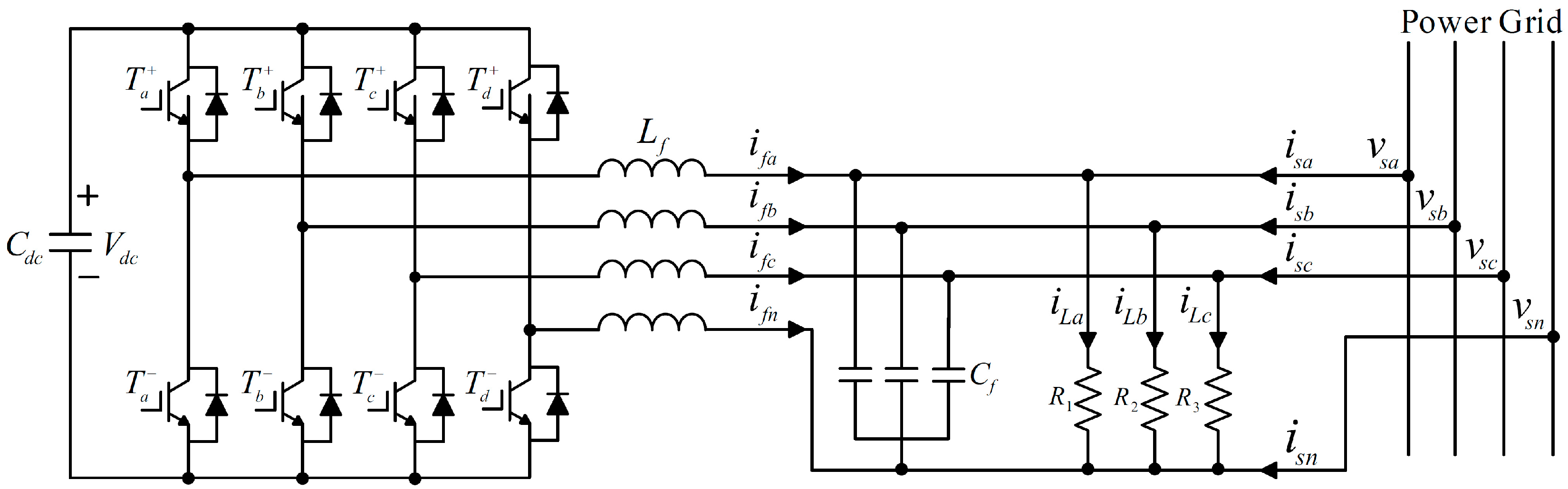
Figure 2.
Control scheme of shunt APF.
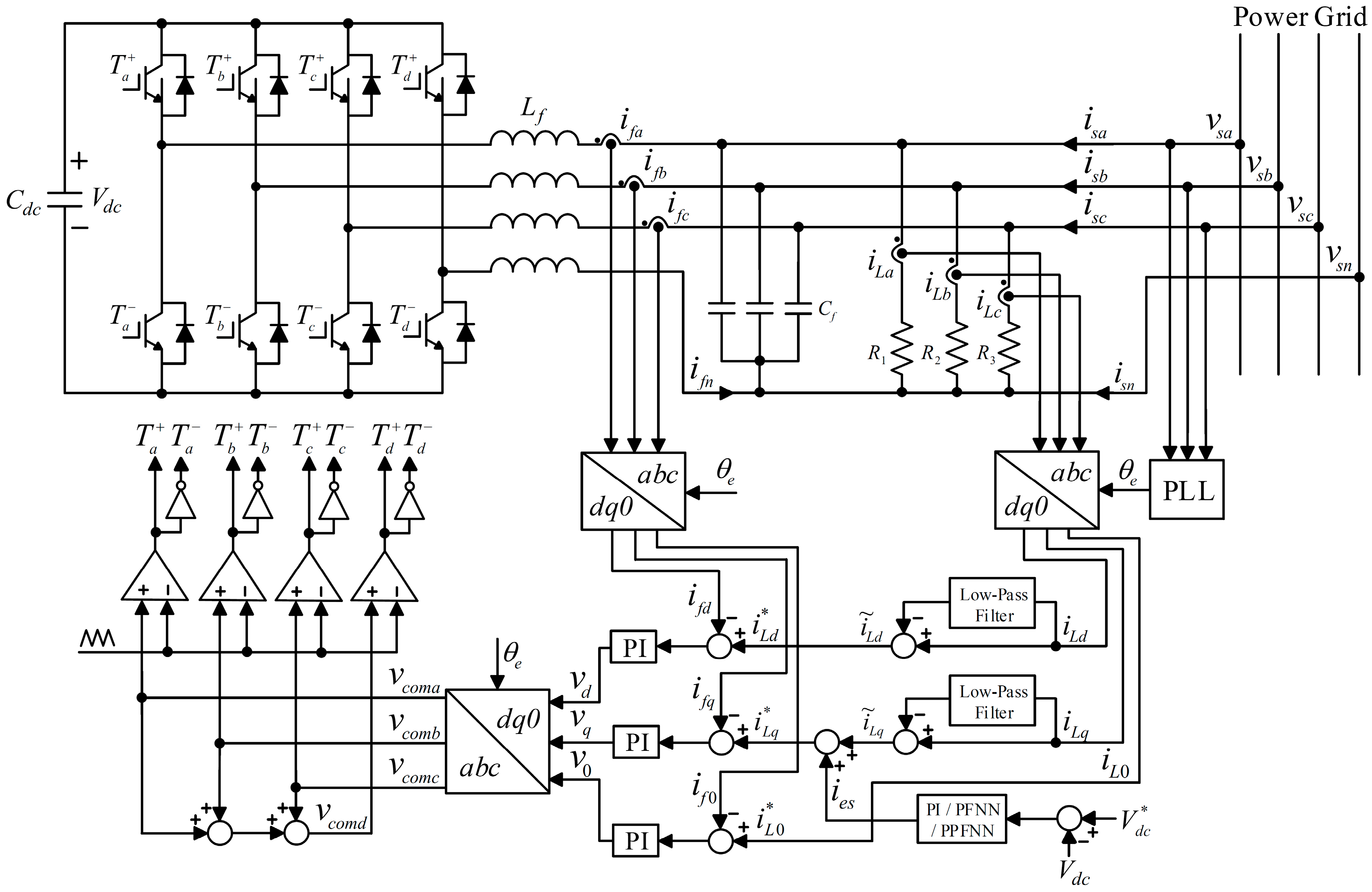
Figure 3.
Network structure of PPFNN.

Figure 4.
DSP-based shunt APF: (a) Block diagram of three-phase four-leg inverter-based shunt APF; (b) Photos of DSP-based control platform, unbalanced loads and inverter; and (c) Photo of three-phase four-leg inverter.
Figure 4.
DSP-based shunt APF: (a) Block diagram of three-phase four-leg inverter-based shunt APF; (b) Photos of DSP-based control platform, unbalanced loads and inverter; and (c) Photo of three-phase four-leg inverter.
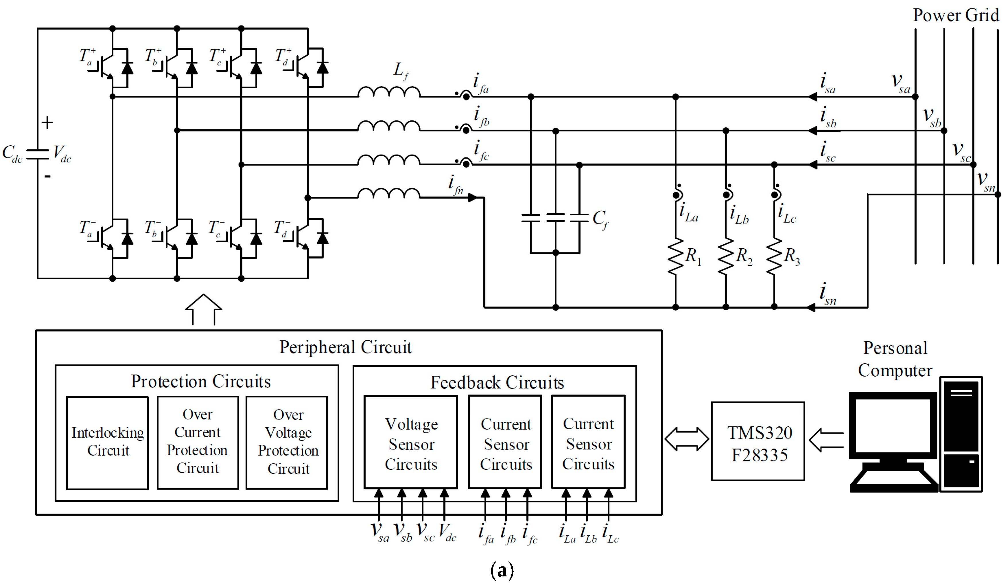

Figure 5.
Experimental results at unbalanced load 1: (a) Responses of three-phase currents isa, isb, isc and neutral current isn without using shunt APF; (b) Responses of three-phase currents isa, isb, isc and neutral current isn using PI controlled shunt APF; (c) Responses of DC-link voltage Vdc and phase voltage of power grid vsa using PI controlled shunt APF; (d) Responses of three-phase currents isa, isb, isc and neutral current isn using PFNN controlled shunt APF; (e) Responses of DC-link voltage Vdc and phase voltage of power grid vsa using PFNN controlled shunt APF; (f) Responses of three-phase currents isa, isb, isc and neutral current isn using proposed PPFNN controlled shunt APF; and (g) Responses of DC-link voltage Vdc and phase voltage of power grid vsa using proposed PPFNN controlled shunt APF.

Figure 6.
Experimental results at unbalanced load 2: (a) Responses of three-phase currents isa, isb, isc and neutral current isn without using shunt APF; (b) Responses of three-phase currents isa, isb, isc and neutral current isn using PI controlled shunt APF; (c) Responses of DC-link voltage Vdc and phase voltage of power grid vsa using PI controlled shunt APF; (d) Responses of three-phase currents isa, isb, isc and neutral current isn using PFNN controlled shunt APF; (e) Responses of DC-link voltage Vdc and phase voltage of power grid vsa using PFNN controlled shunt APF; (f) Responses of three-phase currents isa, isb, isc and neutral current isn using proposed PPFNN controlled shunt APF; and (g) Responses of DC-link voltage Vdc and phase voltage of power grid vsa using proposed PPFNN controlled shunt APF.
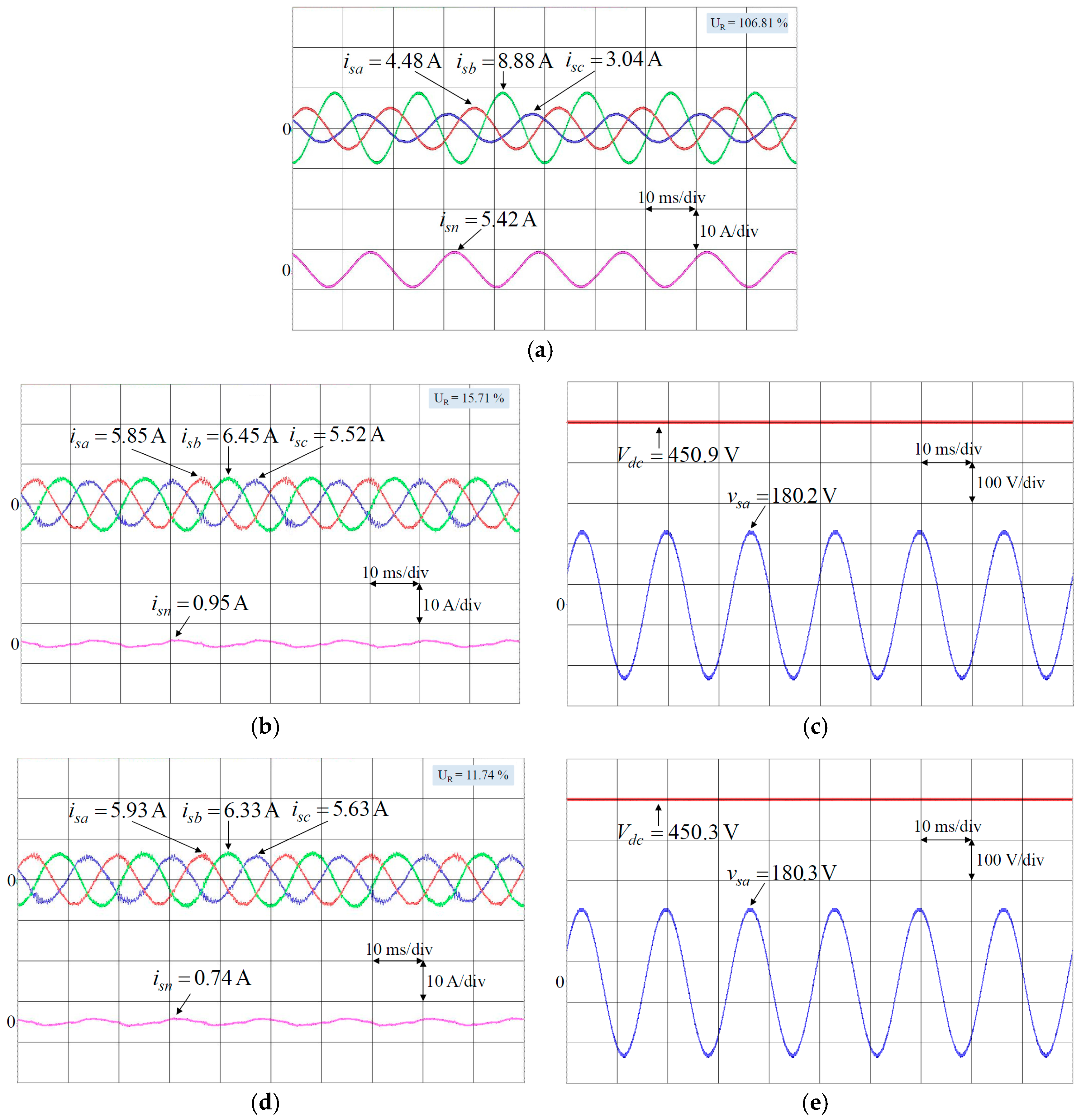

Figure 7.
Experimental results at unbalanced load 3: (a) Responses of three-phase currents isa, isb, isc and neutral current isn without using shunt APF; (b) Responses of three-phase currents isa, isb, isc and neutral current isn using PI controlled shunt APF; (c) Responses of DC-link voltage Vdc and phase voltage of power grid vsa using PI controlled shunt APF; (d) Responses of three-phase currents isa, isb, isc and neutral current isn using PFNN controlled shunt APF; (e) Responses of DC-link voltage Vdc and phase voltage of power grid vsa using PFNN controlled shunt APF; (f) Responses of three-phase currents isa, isb, isc and neutral current isn using proposed PPFNN controlled shunt APF; and (g) Responses of DC-link voltage Vdc and phase voltage of power grid vsa using proposed PPFNN controlled shunt APF.
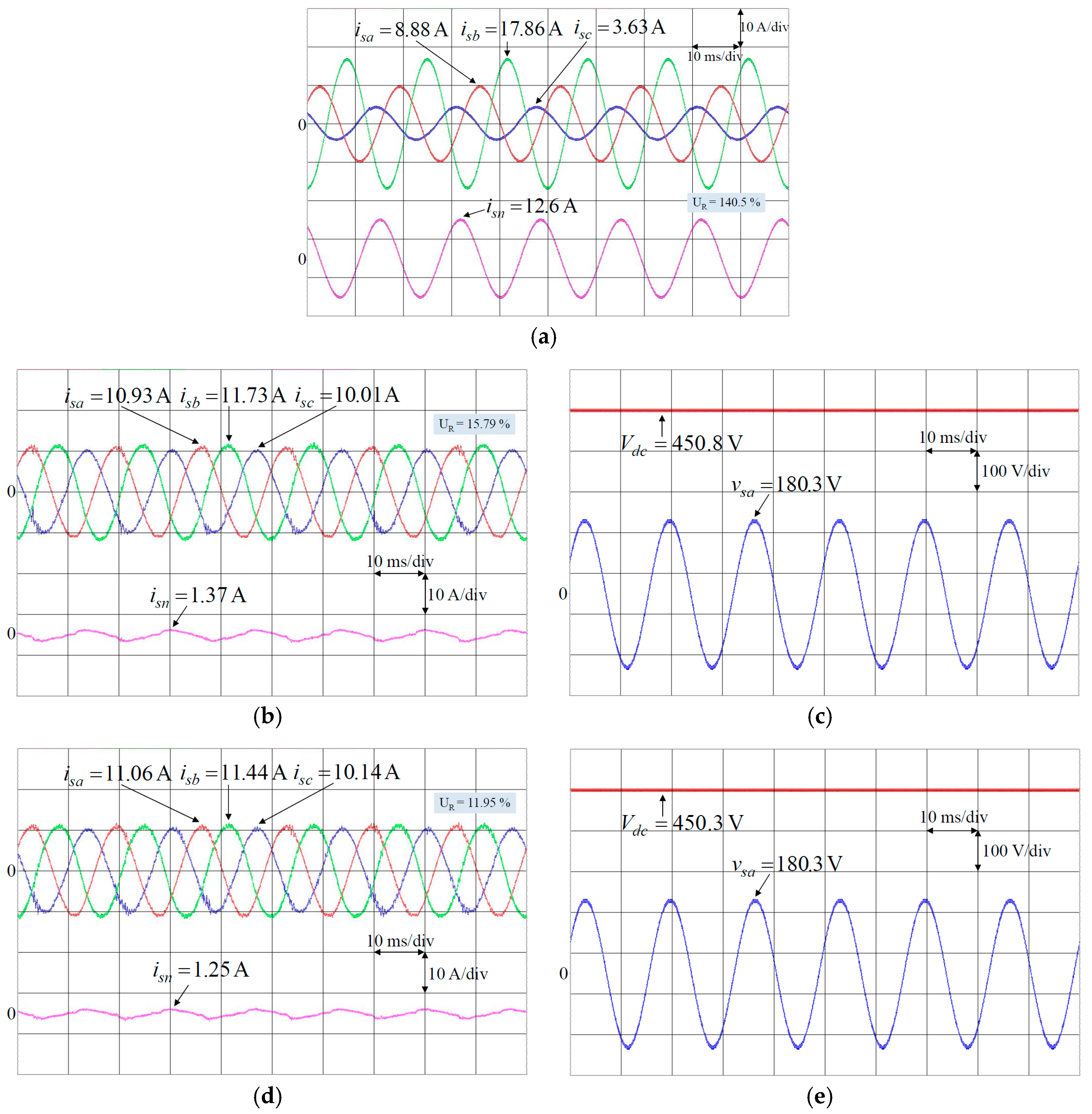
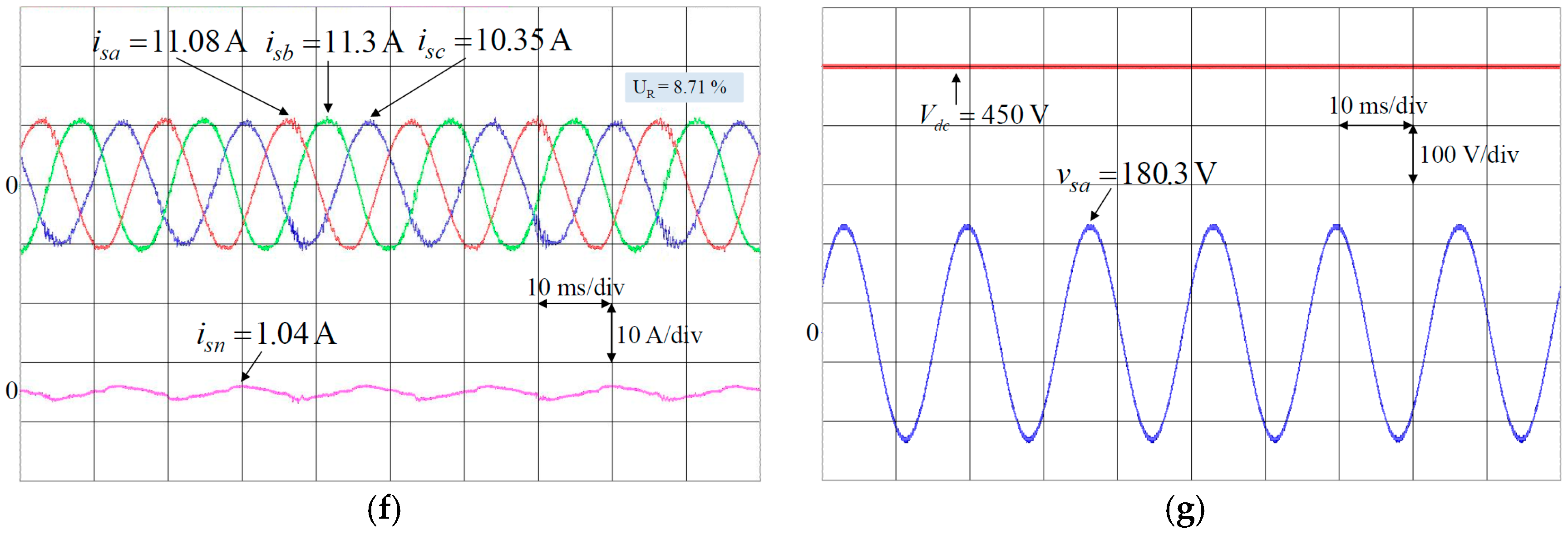
Figure 8.
Experimental results at unbalanced load 3 under abnormal grid voltage: (a) Response of grid voltage with 0.2 pu voltage dip at load 3; (b) Responses of three-phase currents isa, isb, isc and neutral current isn without using shunt APF; (c) Responses of three-phase currents isa, isb, isc and neutral current isn using PI controlled shunt APF; (d) Response of DC-link voltage Vdc using PI controlled shunt APF; (e) Responses of three-phase currents isa, isb, isc and neutral current isn using PFNN controlled shunt APF; (f) Response of DC-link voltage Vdc using PFNN controlled shunt APF; (g) Responses of three-phase currents isa, isb, isc and neutral current isn using proposed PPFNN controlled shunt APF; and (h) Response of DC-link voltage Vdc using proposed PPFNN controlled shunt APF.
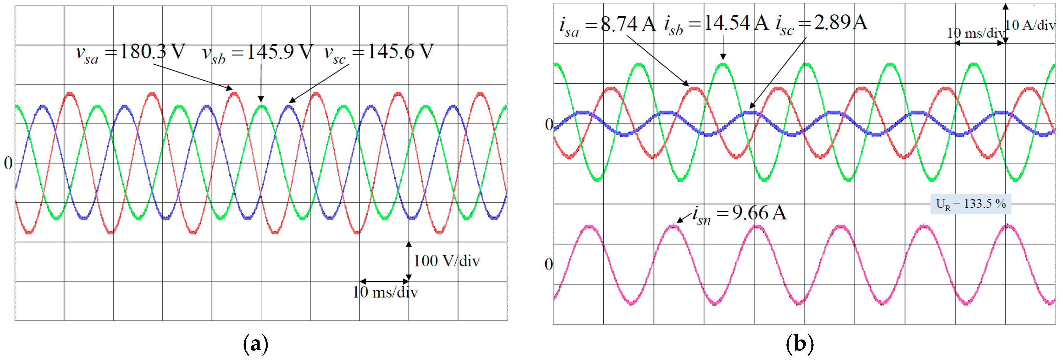

Figure 9.
Experimental results at case 1: (a) Responses of three-phase currents isa, isb, isc and regulation control of DC-link voltage using PI controlled shunt APF; (b) Responses of three-phase currents isa, isb, isc using PI controlled shunt APF in 0.54–0.74 s; (c) Responses of three-phase currents isa, isb, isc and regulation control of DC-link voltage using PFNN controlled shunt APF; (d) Responses of three-phase currents isa, isb, isc using PFNN controlled shunt APF in 0.54–0.74 s; (e) Responses of three-phase currents isa, isb, isc and regulation control of DC-link voltage using proposed PPFNN controlled shunt APF (f) Responses of three-phase currents isa, isb, isc using proposed PPFNN controlled shunt APF in 0.54–0.74 s.

Figure 10.
Experimental results at case 2: (a) Responses of three-phase currents isa, isb, isc and regulation control of DC-link voltage using PI controlled shunt APF; (b) Responses of three-phase currents isa, isb, isc using PI controlled shunt APF in 0.54–0.74 s; (c) Responses of three-phase currents isa, isb, isc and regulation control of DC-link voltage using PFNN controlled shunt APF; (d) Responses of three-phase currents isa, isb, isc using PFNN controlled shunt APF in 0.54–0.74 s; (e) Responses of three-phase currents isa, isb, isc and regulation control of DC-link voltage using proposed PPFNN controlled shunt APF (f) Responses of three-phase currents isa, isb, isc using proposed PPFNN controlled shunt APF in 0.54–0.74 s.


Table 1.
Three-phase unbalanced current ratio using different controllers.
| Active Compensation | DC-Link Voltage Control Algorithm | Three-Phase Unbalanced Current Ratio UR (%) | ||
|---|---|---|---|---|
| Load 1 | Load 2 | Load 3 | ||
| Without APF | - | 93.72 | 106.81 | 140.5 |
| APF | PI | 17.41 | 15.71 | 15.79 |
| APF | PFNN | 14.83 | 11.74 | 11.95 |
| APF | PPFNN | 10.75 | 8.55 | 8.71 |
Table 2.
Response time of DC-link voltage and maximum DC-link voltage error in transient state using different controllers.
Table 2.
Response time of DC-link voltage and maximum DC-link voltage error in transient state using different controllers.
| DC-Link Voltage Control Algorithm | Response Time (s) | Overshoot to Undershoot (V) | ||
|---|---|---|---|---|
| Load 1Load 3 | Load 2Load 1 | Load 1 Load 3 | Load 2Load 1 | |
| PI | 0.8 | 0.7 | 31 | 12 |
| PFNN | 0.4 | 0.4 | 17 | 7 |
| PPFNN | 0.2 | 0.12 | 9 | 4 |
Table 3.
Execution time of shunt APF using PI, PFNN and proposed PPFNN controllers.
| Controllers | PI | PFNN | Proposed PPFNN |
|---|---|---|---|
| Execution Time | 0.023 ms | 0.1771 ms | 0.1992 ms |
© 2017 by the authors. Licensee MDPI, Basel, Switzerland. This article is an open access article distributed under the terms and conditions of the Creative Commons Attribution (CC BY) license (http://creativecommons.org/licenses/by/4.0/).
Share and Cite
MDPI and ACS Style
Tan, K.-H.; Lin, F.-J.; Chen, J.-H. A Three-Phase Four-Leg Inverter-Based Active Power Filter for Unbalanced Current Compensation Using a Petri Probabilistic Fuzzy Neural Network. Energies 2017, 10, 2005. https://doi.org/10.3390/en10122005
AMA Style
Tan K-H, Lin F-J, Chen J-H. A Three-Phase Four-Leg Inverter-Based Active Power Filter for Unbalanced Current Compensation Using a Petri Probabilistic Fuzzy Neural Network. Energies. 2017; 10(12):2005. https://doi.org/10.3390/en10122005
Chicago/Turabian StyleTan, Kuang-Hsiung, Faa-Jeng Lin, and Jun-Hao Chen. 2017. "A Three-Phase Four-Leg Inverter-Based Active Power Filter for Unbalanced Current Compensation Using a Petri Probabilistic Fuzzy Neural Network" Energies 10, no. 12: 2005. https://doi.org/10.3390/en10122005
Note that from the first issue of 2016, this journal uses article numbers instead of page numbers. See further details here.