Hybrid Hydrogen and Mechanical Distributed Energy Storage

1
Department of Economics, Engineering, Society and Business Organization, University of Tuscia, 01100 Viterbo, Italy
2
Dipartimento di Ingegneria dell’Impresa “Mario Lucertini”, University of Roma Tor Vergata, 00133 Roma, Italy
*
Author to whom correspondence should be addressed.
Energies 2017, 10(12), 2035; https://doi.org/10.3390/en10122035
Submission received: 29 September 2017
/
Revised: 23 November 2017
/
Accepted: 30 November 2017
/
Published: 2 December 2017
(This article belongs to the Section D: Energy Storage and Application)
Abstract
:Effective energy storage technologies represent one of the key elements to solving the growing challenges of electrical energy supply of the 21st century. Several energy storage systems are available, from ones that are technologically mature to others still at a research stage. Each technology has its inherent limitations that make its use economically or practically feasible only for specific applications. The present paper aims at integrating hydrogen generation into compressed air energy storage systems to avoid natural gas combustion or thermal energy storage. A proper design of such a hybrid storage system could provide high roundtrip efficiencies together with enhanced flexibility thanks to the possibility of providing additional energy outputs (heat, cooling, and hydrogen as a fuel), in a distributed energy storage framework. Such a system could be directly connected to the power grid at the distribution level to reduce power and energy intermittence problems related to renewable energy generation. Similarly, it could be located close to the user (e.g., office buildings, commercial centers, industrial plants, hospitals, etc.). Finally, it could be integrated in decentralized energy generation systems to reduce the peak electricity demand charges and energy costs, to increase power generation efficiency, to enhance the security of electrical energy supply, and to facilitate the market penetration of small renewable energy systems. Different configurations have been investigated (simple hybrid storage system, regenerate system, multistage system) demonstrating the compressed air and hydrogen storage systems effectiveness in improving energy source flexibility and efficiency, and possibly in reducing the costs of energy supply. Round-trip efficiency up to 65% can be easily reached. The analysis is conducted through a mixed theoretical-numerical approach, which allows the definition of the most relevant physical parameters affecting the system performance.
1. Introduction
Safety, security, and economical sustainability of energy supply are among the main concerns of industrialized countries. These issues are particularly critical for the European Union (EU) where energy imports share more than 50% of the gross primary energy consumption. Moreover, energy consumption is strongly related to climate changes, as more than 80% of the overall greenhouse gas emissions results from fuel combustion. Thereafter, a key component of the EU energy policy is the commitment of achieving a 20% energy saving by 2020, compared to the business-as-usual scenario. The total energy investment worldwide in 2016 was just over $1.7 trillion. Spending in energy efficiency rose by 9% while spending in electricity networks rose by 6%, yet these increases were more than offset by a continuing drop in investment in upstream oil and gas, which fell by over a quarter, and power generation, down 5%. Falling unit capital costs, especially in upstream oil and gas, and solar photovoltaics (PV), was a key reason for lower investment, though reduced drilling and less fossil fuel-based power capacity also contributed [1].
In the last decades, the structure and the philosophy of energy conversion and supply have been significantly changing. In particular, the development of a competitive electricity market is promoting distributed generation, (DG) (i.e., placing relatively small scale plants close to consumers), and renewable energy sources (RES). On the contrary, investments in centralized generation, that is based on remotely located large scale plants [2,3,4,5,6,7,8,9] have significantly reduced.
This situation is causing several problems to the electrical power distribution infrastructure. RES and DG increase the supply–demand imbalance, thus reducing the electrical power quality and reliability. The concurrent factors are the variable and intermittent output of the RES and the scarce power regulation capability of large traditional power plants (e.g., coal, nuclear, and combined cycles). In this scenario, energy storage is becoming essential. A further significant increment of the RES penetration and of DG will be effective only if coupled with an adequate electricity storage capacity [10,11].
A remarkable research effort and large investments in electricity storage have led to a wide variety of energy storage systems. Several technologies are available, from mature to pre-commercial to experimental: pumped hydroelectric storage, rechargeable batteries, superconducting magnets, flywheels, electrolyzers, and compressed air systems are a few examples. Each technology has its inherent limitations related to the working principle that make its use economical or practically feasible only for specific applications, a certain power or energy range, and a definite operation time.
The objective of this paper is to identify possible combinations of the energy storage technologies to establish positive synergies between different storage systems. In particular, we seek to demonstrate that compressed air and hydrogen energy storage can be efficiently combined with several positive effects: increasing the efficiency of the energy system, reducing costs and environmental externalities, making renewable energy smooth and dispatchable, and improving energy source flexibility.
Compressed Air Energy Storage (CAES) is based on the idea of storing energy in the form of high pressure compressed air and then releasing the compressed air through an expander to generate mechanical power [12,13,14,15]. CAES integrates different interacting components, devices, and processes, such as compressors, expanders, and electrical machines. CAES is often combined with other energy storage technologies to achieve the required energy capacity, density, response time, and efficiency [10,16]. Despite the ability of CAES technology to be effective for a very large power range (i.e., from tens of kW to hundreds of MW) and for different storage durations (i.e., from daily to seasonal), only two large-scale energy plants exist [12], due to large capital costs and size effects on the machines efficiency [17].
The working principle of a conventional large-scale CAES is similar to the one of a gas turbine, except that, in a CAES, compression and expansion are not contemporary. They do not present any particular technological issue, except for the necessity of guaranteeing a sufficiently high temperature of the air entering the expander to avoid turbine freezing. Three options have been proposed so far [10,17,18,19,20]:
- Adiabatic system: heat generated by compression is stored and then returned to the air before expansion. The expected round-trip efficiency is around 60% (although theoretically 100%).
- Diabatic system: the compression heat is dissipated into the atmosphere via heat intercoolers. The air is heated before entering the turbines. The expected round-trip efficiency is in the range of 40% to 50%.
- Isothermal systems: the temperature of the working fluid is kept as close as possible to the environment one. When air is compressed, heat dissipates into the atmosphere. Once the air is released to drive and the turbine to produce the electricity, heat is brought in from the external environment.
Also hybrid configurations are possible, as for example that discussed in [21].
Due to technological issues related to the moderately high temperature heat-storage required for adiabatic CAES, the very few practical realizations of CAES are diabatic [22], and use fossil fuels, producing obvious detrimental effects on flexibility, efficiency, and environmental impact. The benefits associated with renewable energy production are partially compromised.
The inspiring idea of our research is to provide the necessary heat by burning hydrogen, which is generated by electrolysis of water. Such a hybrid system would realize the full potential of compressed air storage systems without burning fossil fuels or using high temperature thermal energy storage. Moreover, hydrogen combustion would produce much less harmful emissions than that of fossil fuels [23]. The proposed electrical energy storage technology has also a remarkable commercial attractiveness, given that the worldwide demand for retail and utility-scale energy storage is projected to double every year through 2018, according to [24], and that by 2017 the global market for energy storage will reach 185 GWh, worth on the order of $113 Billion, according to Lux research [25].
This paper is organized as follows: in Section 2 we introduce the state of the art of energy storage. Section 3 thoroughly describes the proposed systems and reports the most relevant performance parameters. Finally, in Section 4 we draw the concluding remarks by comparing the introduced systems, and we highlight the possible future developments.
2. State of the Art and Perspectives of Energy Storage Technologies
Most of the electricity is still produced in centralized large power plants, transported and distributed through the power grid, and traded as any other commodity. Different from other commodities, the electric market has a negligible storage capacity. Therefore, the production must instantaneously match the demand of electricity that varies considerably, daily, and seasonally. The cost of electricity is increased and the electrical system efficiency is reduced by part load plant operations and by frequent cold-start of relatively small generation units. In the last decade, this imbalance has dramatically increased due to the massive deployment of renewable energy systems, mainly wind and solar power. Given that environmental concerns are pushing towards an increased production of electricity from renewable resources in the next years [26,27,28], much work is being done to develop electrical energy storage facilities to compensate for the fluctuating character of this renewable electricity generation.
Policies and projects related to energy storage can be found in the U.S. Department of Energy’s (DOE) International Storage Database [29], which is being used as a reference market research and citation source in this field.
Several possible options for electricity storage have been investigated for both industrial and commercial applications. Mechanical and chemical storage systems dominate the electrical power storage scenario. The proposed hybrid storage systems combine these two technologies.
2.1. Mechanical Storage Systems
Mechanical storage systems include flywheels, in which electricity is transformed into kinetic energy of a massive rotor, pumped-storage hydro, which represents more than 95% of large electricity storage [26], gravity based systems [20], which store mechanical energy by increasing the elevation of a generic mass, and compressed air.
Pumped-hydro is limited by the availability of territories with specific geological and geographical requirements, gravity and flywheels based storage systems are limited by their limited storage capacity.
The only feasible alternative to pumped-hydro for large scale energy storage is represented by CAES [3,4,5,30,31,32,33]. In such systems, mechanical energy is stored in the form of a compressed or even liquefied gas [34].
Considering CAES as a pure storage system is questionable. In fact, an additional energy source might be required, as evidenced in Section 1 for diabatic systems. Large scale CAES systems are applicable only in specific sites, as they require suitable underground geological characteristics to host a feasible air reservoir. However, the same principle could be used to store energy for distributed power networks, as proposed in [12,16], with multipurpose micro-CAES systems that provide energy storage and generation with various heat sources. In this smaller application, air could be also stored over ground.
The literature describes three types of CAES, diabatic, adiabatic, and isothermal, as well as a combination of diabatic and adiabatic CAES, usually named hybrid systems.
In diabatic CAES, the heat generated during the compression is dissipated, mainly to increase thermodynamic efficiency and to minimize the required storage volume, while reducing technical problems related to high temperature compression and storage [35]. The thermal energy necessary to avoid freezing in the expander is provided by fossil fuel combustion. Two of these systems are in operation and can reach roundtrip efficiencies around 50% [10]. However, the need of using fossil fuels is an impassable barrier to their further development in the next decades.
In the adiabatic CAES [28,36] the compressed thermal energy is retained in thermal storage, and then utilized to heat the compressed air before entering the turbine. Thus, no fossil fuel combustion is required. Several studies and techno-economic assessments on adiabatic CAES are available in the literature, in combination with renewable energy systems or connected to the power grid [29,30,31,32,33,34,35,36,37,38,39,40,41,42,43]. They promise efficiencies up to 65–70%, but no plants of this type exist so far, mainly for the high investment costs, the complexity of the system, and the technological barriers to moderately high temperature heat storage.
A similar concept is the isothermal CAES, where the air temperature is kept constant by exchanging heat with the environment during both the storage phase and the expansion [30].
2.2. Chemical and Electrochemical Storage Systems
Chemical and electrochemical storage systems include batteries, super- and ultra-capacitors, and hydrogen and power-to-gas technologies.
A lot of research is being performed on electric batteries, whose development is of interest in many other fields such as portable devices and automotive industries. Although their use to store large amounts of electrical energy has attracted some interest [29], mainly because of their commercial availability, batteries require a great deal of maintenance, have a limited number of charging-discharging cycles, and pose environmental concerns at the end of their life.
Hydrogen energy storage (HES) has attracted a lot of investments and research efforts in the last two decades. Hydrogen can be generated by the electrolysis of water in electrochemical cells and utilized in fuel cells both for stationary and moving applications. Electrolysis is a well-known established process and may be efficiently coupled to the power grid or directly to a source of renewable or traditional electrical energy. Moreover, energy can be stored for long periods, permitting supply and demand load levelling for hourly to seasonal variations. Finally, H2 storage can be tailored to the requirements of each specific application without significant efficiency losses. This kind of technology is only available for small and medium power applications due to cost concerns and technological problems.
Several kinds of water electrolysis technologies are available to date. The calorific energy content of hydrogen is about 39 kWh/kg. Taking into account the process inefficiencies, it takes over 50 kWh of electricity to generate 1 kg of hydrogen. The conversion efficiency of the electrolyzers used to create hydrogen is between 60% and 90% depending on the current and the materials used for the electrolytes and the electrodes [44]. When the prime purpose of the electrolyzer is to store surplus electricity generated by solar or wind power for subsequent use in a fuel cell, the “round-trip efficiency” of the storage process (electricity to hydrogen and back to electricity) is between 30% and 50%. This compares unfavorably with battery storage where the round-trip efficiency, known as the Coulombic efficiency in battery parlance, is over 90% for a lead acid battery and even more for a lithium battery [45].
Alkaline electrolyte systems [46,47,48] are commercially available and have efficiencies in the range of 55% to 70%. A remarkable research effort is on-going to obtain higher efficiency by increasing operating temperature or pressure, but the main technical difficulties are maintaining the electrolyte balance and keeping hydrogen and oxygen separated.
High purity hydrogen can be produced in polymer electrolyte membrane (PEM) electrolyzers, which are capable of accepting large power input variations, thus allowing direct integration with intermittent sources of energy such as renewable energy systems [48]. They also allow high-pressure operation and may be reversible [49]. Operating temperatures are in the range 50–150 °C, but preferably below 100 °C to guarantee an acceptable lifetime of the membrane, which is a limiting issue for this technology. The efficiency of such systems in in the range of 70% to 90%.
A particularly promising principle of electrolysis is high temperature electrolysis (HTE), where water is electrolyzed at temperatures between 700 and 1000 °C, using a solid-oxide electrolyte. These systems are characterized by reduced electrochemical overvoltage that increases the efficiency with respect to conventional electrolysis [50]. Even if this technology still requires substantial research and development efforts, there have been some demonstrations of renewable energy hydrogen systems, where hydrogen is generated using solar [51,52,53,54] or wind energy [55]. Moreover, it represents an attractive energy storage option when heat is available from other sources, as it can be embedded in the process to reduce electric energy input and enhance electrolysis efficiency.
3. Analysis and Discussion of the Proposed Hybrid Storage Layouts
The energy storage systems analyzed in the present paper include different energy sources and several electrical, thermal, and fuel energy flows. Therefore, interactions and interdependencies are extremely important to better understand and exploit the potential co-benefits that could increase the reliability and the performance and reduce costs. In this paper, we focus on energy systems integration. The analysis, design, and control of these interactions is addressed with a simplified thermodynamic approach.
The major challenge of these hybrid systems is the determination of the optimal trade-off among flexibility, technological barriers, and capital costs, because higher flexibility typically implies higher revenues at the expense of larger equipment size.
In the study of the energy storage layouts, the following elements should be taken into proper consideration.
- Electrical energy is stored in the form of compressed gas and hydrogen.
- Hydrogen is generated to provide a high temperature gas flow at the expander inlet. Such a temperature could be varied in order to optimize the system performances.
- Heat fluxes need to be properly optimized. In fact, the possible sources of heat are the gas at the compressor outlet and, for some specific operating conditions, the gas at the turbine exhaust. Intercooling during the compression phase, re-heating during the expansion phase, and regeneration are other possible options to improve the overall charge-discharge efficiency.
In distributed small power applications, when the energy storage system is close to the user, the heat available after the compression or the expansion process may be used for cogeneration purposes. Moreover, by regulating the inlet temperature of the expander through the hydrogen flow rate, cold temperatures may be produced at the expander outlet. In such a configuration, the whole storage system may be used as a trigenerative energy system, simultaneously producing electrical energy, heat (compressor outlet), and chilling (turbine outlet). If we consider such an energy storage system coupled to a renewable energy system, we could in principle obtain a “zero-emission” trigenerative energy system.
3.1. Simple Hybrid Storage System
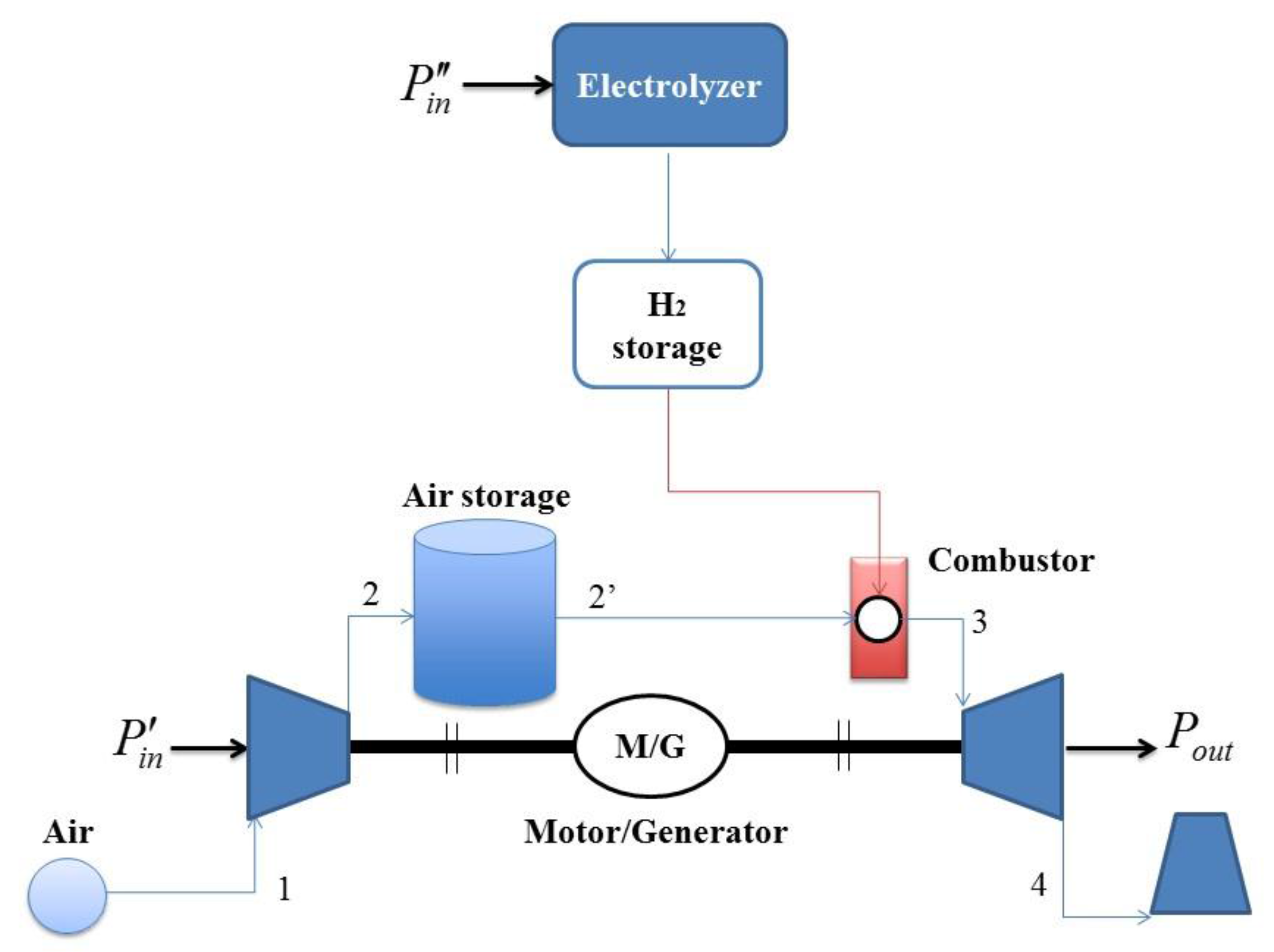
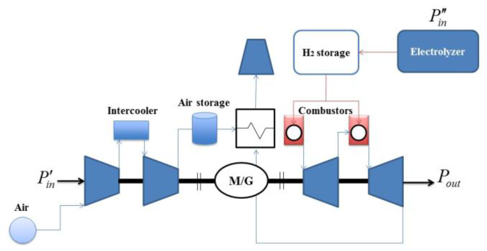
The simplest configuration of a hybrid system is shown in Figure 1. It consists of four main components: compressor, turbine, air storage, and hydrogen storage.
When electrical energy is consumed, part of the electrical power () is used to drive the compressor, and the working fluid is pumped into a reservoir. The charging process ends when the pressure in the reservoir reaches a predetermined maximum value. The rest of the electrical power from the grid () is used by the electrolyzer to produce hydrogen.
To provide electrical energy to the power grid, the compressed air and the hydrogen are burnt together in a combustor. The hot gas flow, composed of air and water steam, expands in the turbine to produce the electrical power output (). The expander inlet temperature is regulated by modifying the air-fuel ratio. In this case, the electrolyzer has mainly the accessory function of avoiding excessively low temperatures in the expander.
We assume that the compression is adiabatic and that air is a perfect gas. The compression power is:
where is the inlet mass flow rate, βc is the compression pressure ratio, is the average constant pressure specific heat in the generic thermodynamic transformation between i and j, T2s is the isentropic outlet temperature, T1 the environment temperature, and , where R is the air constant. stands for the overall efficiency of the compressor, which includes the isentropic efficiency and all electro-mechanical losses.
We assumed that the molecular weight of air is 28.9 kg/kmole such that R = 8314 J/(kmol·K)/28.9 kg/kmole = 0.286 kJ/(kg·K). According to [56], we assumed that cpij varies linearly with the temperature.
The rest of the electrical power is used to produce hydrogen as follows:
where is the produced hydrogen mass flow rate, is the lower heating value of hydrogen, and is the efficiency of the electrolyzer.
During the discharging phase, hydrogen is burnt to increase the air temperature at the storage outlet () up to the maximum temperature (). If we neglect the pressure drop within the combustion chamber, the following thermodynamic relationships can be written:
where is the combustor efficiency and is the air-fuel ratio. Combining Equations (3) and (4), we obtain:
The temperature depends on the type of the air storage system, on the storage duration, and on the heat exchange between stored air and ambient air. In any case, we can assume:
where a parameter that measures the heat losses in the storage and is a parameter that is equal to 1 for an ideal compression (i.e., = 1). We note that .
Combining Equations (5) and (6), we obtain:
The electric power produced by the turbine can be calculated as follows:
where is the overall efficiency of the turbine, which includes the isentropic efficiency and all electro-mechanical losses, and .
Therefore, the roundtrip efficiency of the hybrid storage system can be calculated as follows:
where .
Combining Equations (2) and (9), we obtain the following alternative relationship:
As an example, we consider a storage system with ηel = 0.80, ηt = 0.9, ηc = 0.9, and ηcc = 0.98, and we study its performance as a function of τ, ξ, and βc. Since the focus of this paper is on the thermodynamic assessment of the concept of a hybrid storage system, we neglect the effects of the air reservoir size. In other terms, we are considering that such a volume is large enough to assume that the pressure and the temperature are constant within the reservoir. To account for pressure losses, we consider that βe = 0.9βc. Note that T2’ is determined only by the temperature of the storage. In turn, under the hypothesis of a very large reservoir, such a temperature is not influenced by the enthalpy of the inlet flow from the compressor. Therefore, the following extreme conditions occur:
- all the heat of compression is dissipated into the atmosphere as waste ;
- all the heat of compression is kept and returned to air before entering the turbine .
When no hydrogen is stored and burnt before expansion, which is to say when and , the latter condition refers to a standard adiabatic CAES.
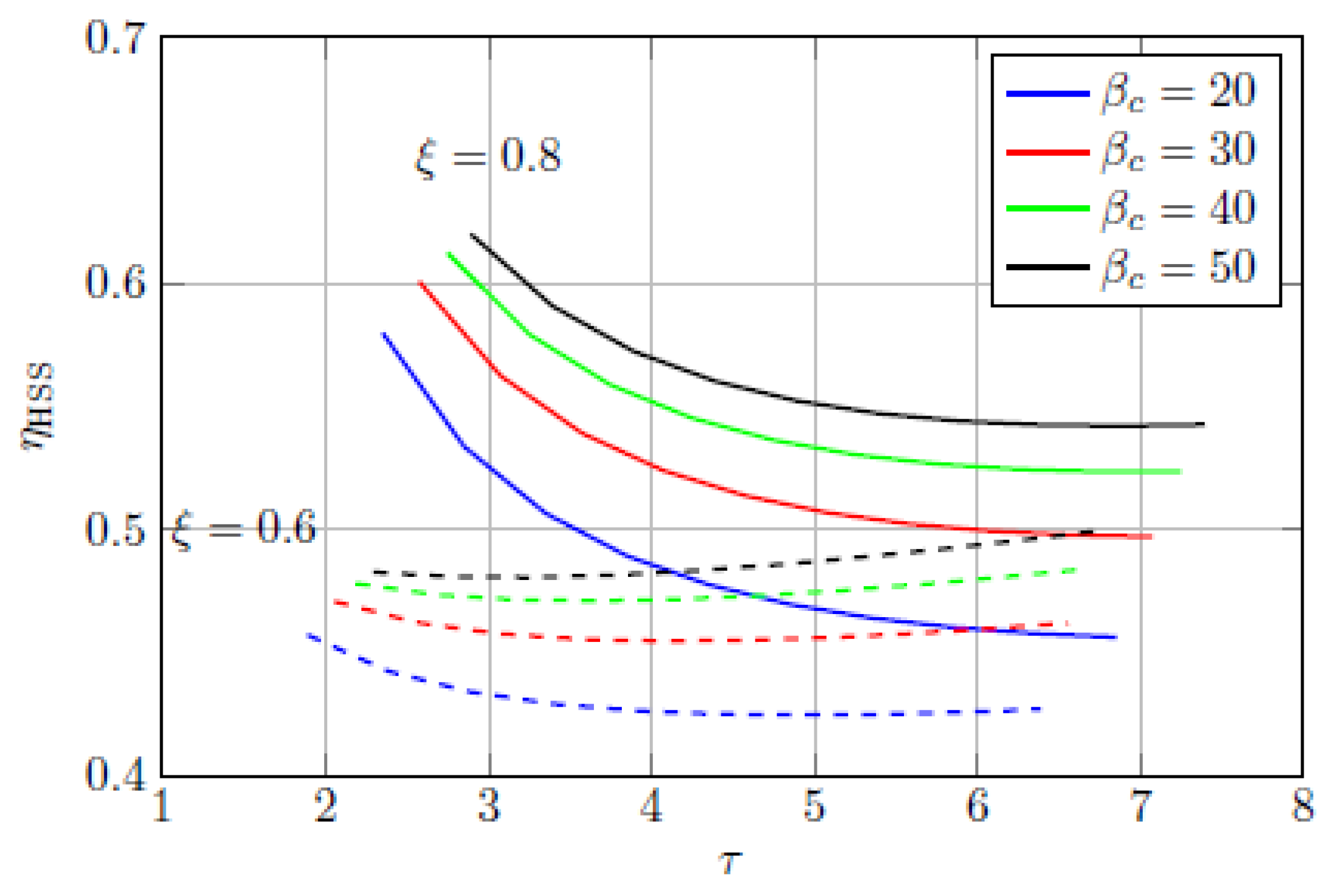
Figure 2 shows the roundtrip efficiency as a function of τ for different values of βc and ξ. When (i.e., ξ ≥ 0.8, with ξ = 0.8 continuous lines), the round-trip efficiency is at a maximum without hydrogen production and storage and tends to diminish with increasing values of τ. On the other hand, for lower values of ξ (i.e., 0.6, dashed lines), the combination of compressed air and hydrogen has a positive effect and the round-trip efficiency increases with τ. Therefore, if the heat produced in the compression phase cannot be stored, the introduction of hydrogen storage in a compressed air system is positive.
The round-trip efficiency is enhanced as the compression ratio, βc, increases, however, the effect of βc reduces with increasing values of τ.
3.2. Regenerated System
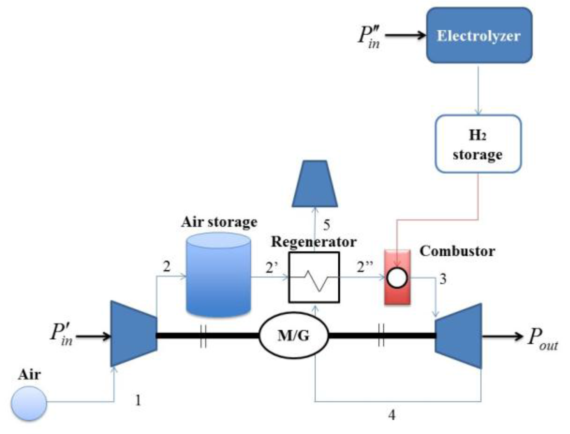
Regeneration is a possible option to improve efficiency, as shown in Figure 3. Regeneration is feasible only for . High T3 and low T2’ facilitate regeneration. This means that, in the regenerated scheme, the portion of the power input dedicated to the electrolyzer is significant.
Being T4 and T5, the air flow temperatures before and after the regenerator, the energy balance in the regenerator reads:
The temperature at the regenerator exhaust can be calculated as:
where is the temperature approach on the hot side of the regenerator.
The thermal energy balance in the combustor is:
Accordingly, the electrical power necessary to produce hydrogen is:
Assuming that , from Equation (8), we can calculate as:
Therefore, the round-trip efficiency of the regenerated system can be written as:
From Equation (15) we note that if , or equivalently , the power produced by the turbine is . Thus, the CAES efficiency becomes:
The power obtained from the turbine is then slightly lower than (electrical power of the electrolyzer). As a consequence, the power spent in the compression phase is completely lost.
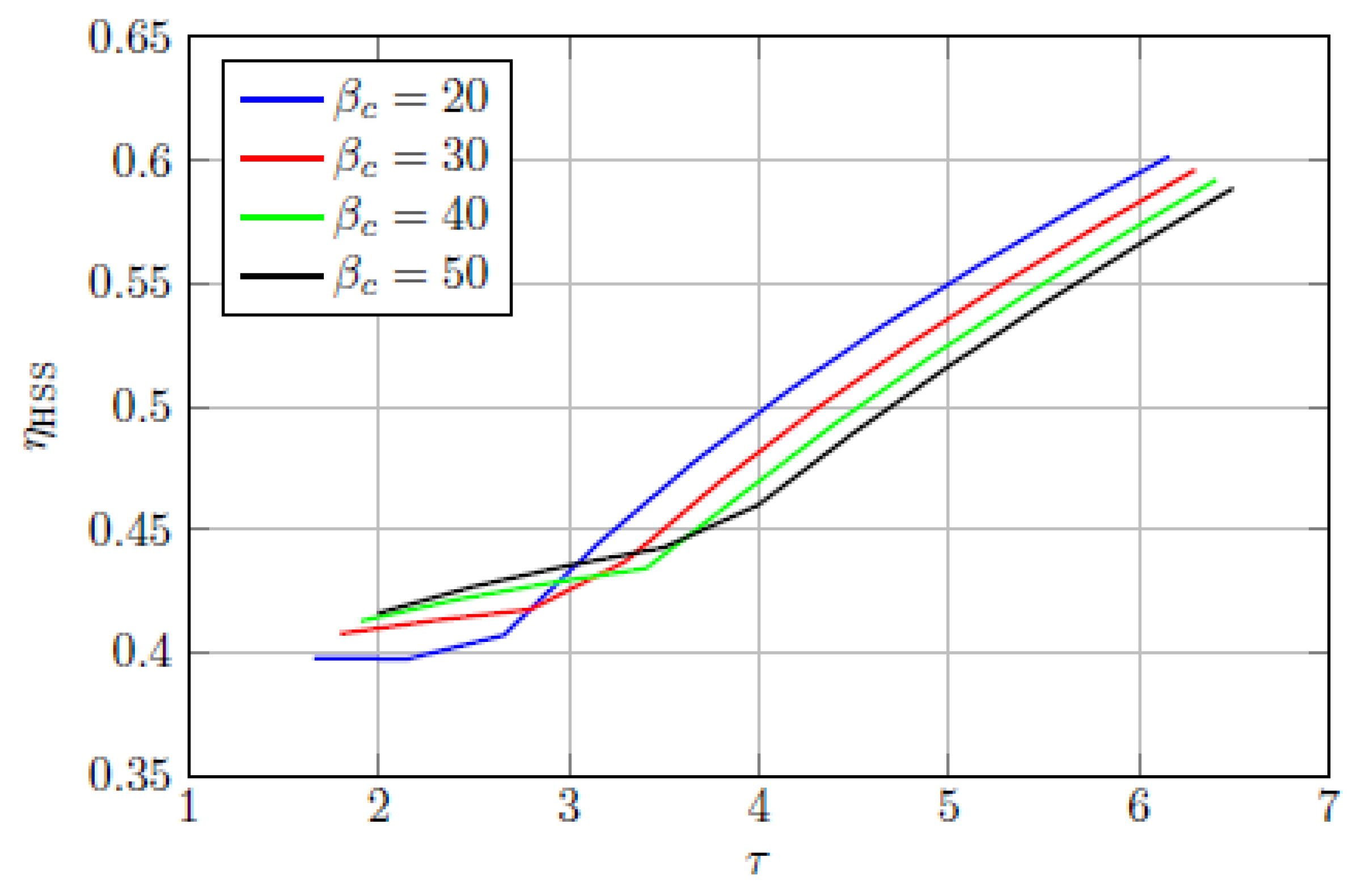
Figure 4 shows the round-trip efficiency of the proposed hybrid storage system (see Equation (16)) as a function of τ, for different values of βc. Therein ξ = 0.5, βe = 0.9βc, ηel = 0.80, ηt = 0.9, ηc = 0.9, and ηcc = 0.98. The effect of the turbine inlet temperature is particularly important, as we observe that the efficiency rapidly grows by increasing τ. This means that the combination of hydrogen and compressed air storage is always positive. As already observed from Equation (17), the effect of βc on the performance of a regenerated system is opposite with respect to the simple system. In this case, with high-τ, ηHSS improves with decreasing βc, and high round-trip efficiencies are obtained with low compression ratios. When , the effect is opposite as regeneration is not performed, which is to say that the system is the simple one.
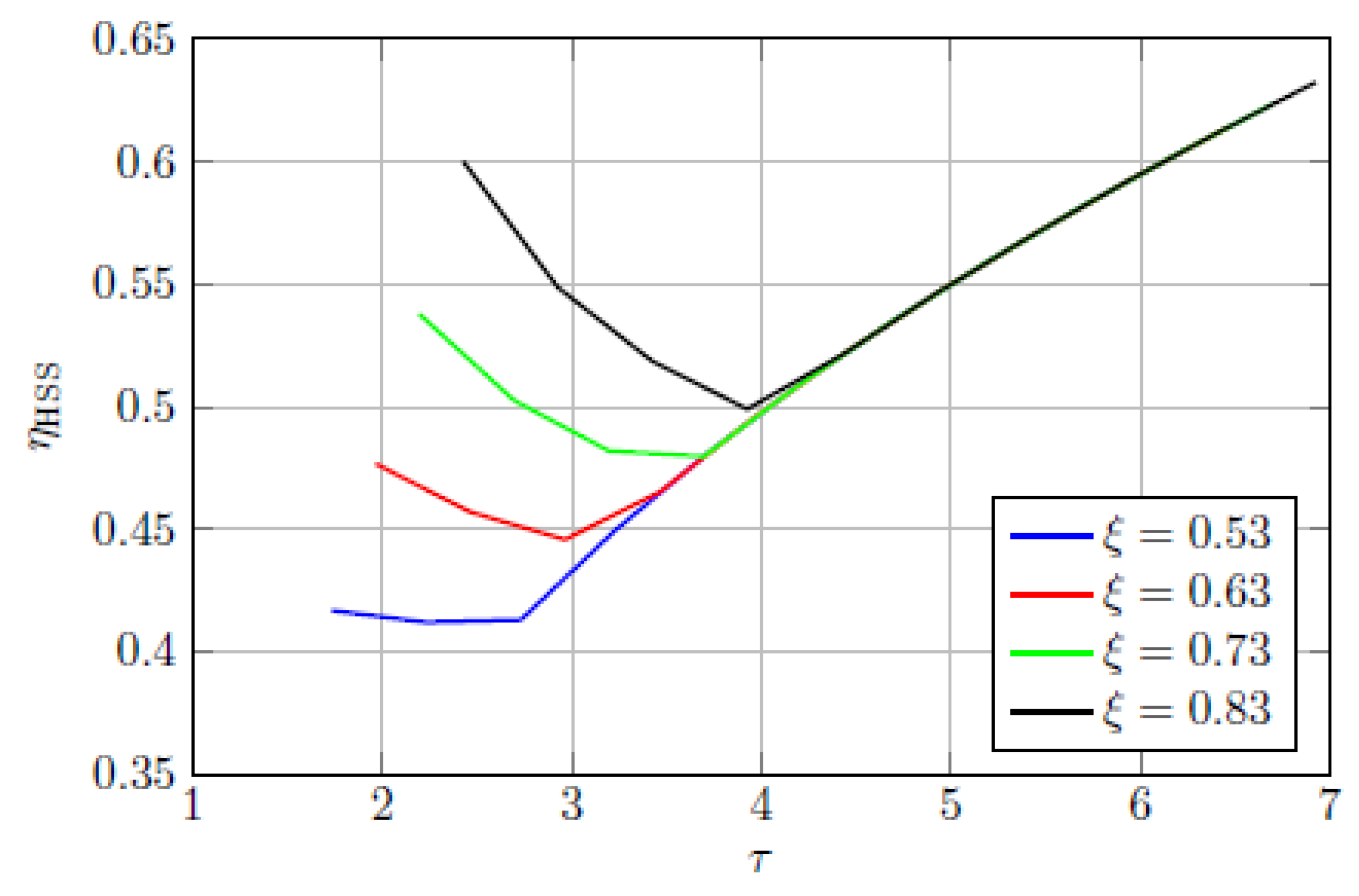
Figure 5 shows the round-trip efficiency of the system as a function of τ for different values of ξ. We note that, in the low-τ area, the efficiency decreases with lower values of ξ, which is to say for higher heat dissipation in the air storage tank. Moreover, the round-trip efficiency does not change with ξ as long as ; in that case, the temperature at the turbine inlet is determined by the regenerator, as shown in Equation (12).
3.3. Multistage Compression and Expansion System
Quasi-isothermal compression/expansion are desirable to increase the efficiency of the system. Therefore, a further improvement of such a system could be obtained by using intercooled compression and/or reheated expansion.
This enhanced configuration is illustrated in Figure 6 and could provide a roundtrip efficiency potentially superior to the separate technologies alone.
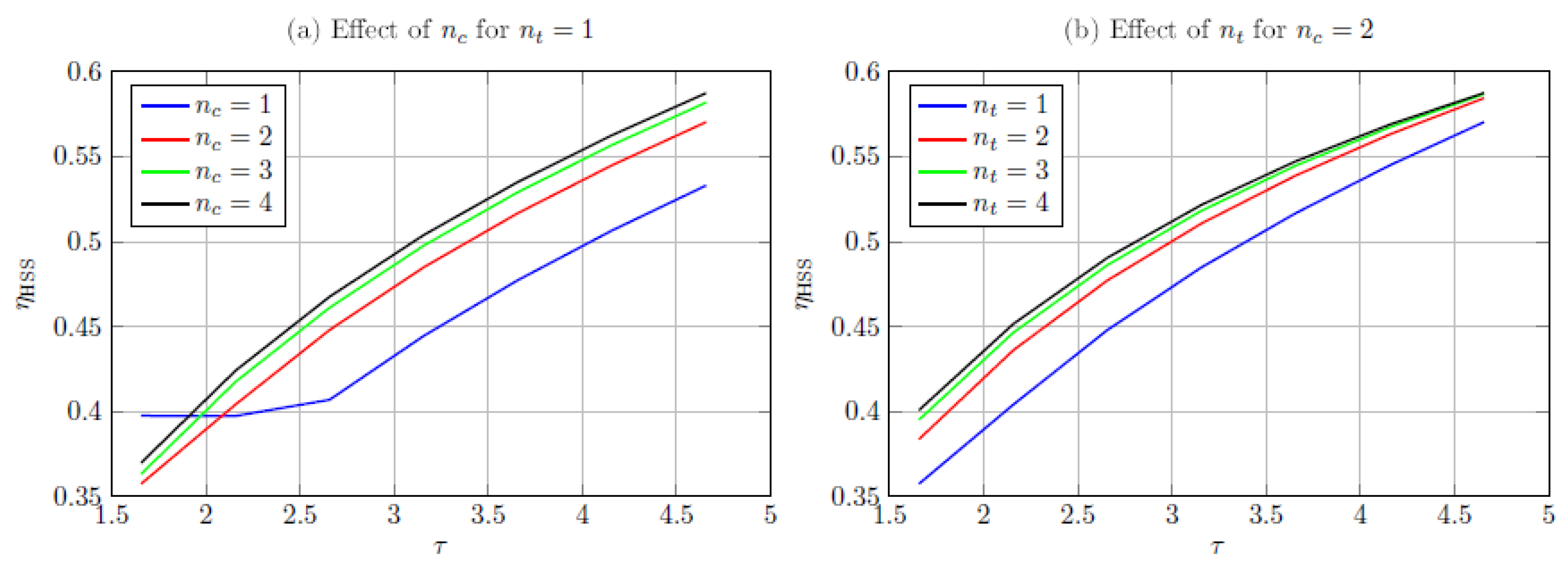
Figure 7 shows the round-trip efficiency of the system as a function of τ, with different numbers of stages of compression and expansion. As expected, the round-trip efficiency is enhanced by increasing the number of stages in both compression and expansion phases. However, this effect goes into saturation very quickly, as we observe that for nc > 3 and/or nt > 3 the marginal increment of efficiency is negligible. Moreover, the higher the turbine inlet temperature, the lower is the effect of increasing the number of compression/expansion stages.
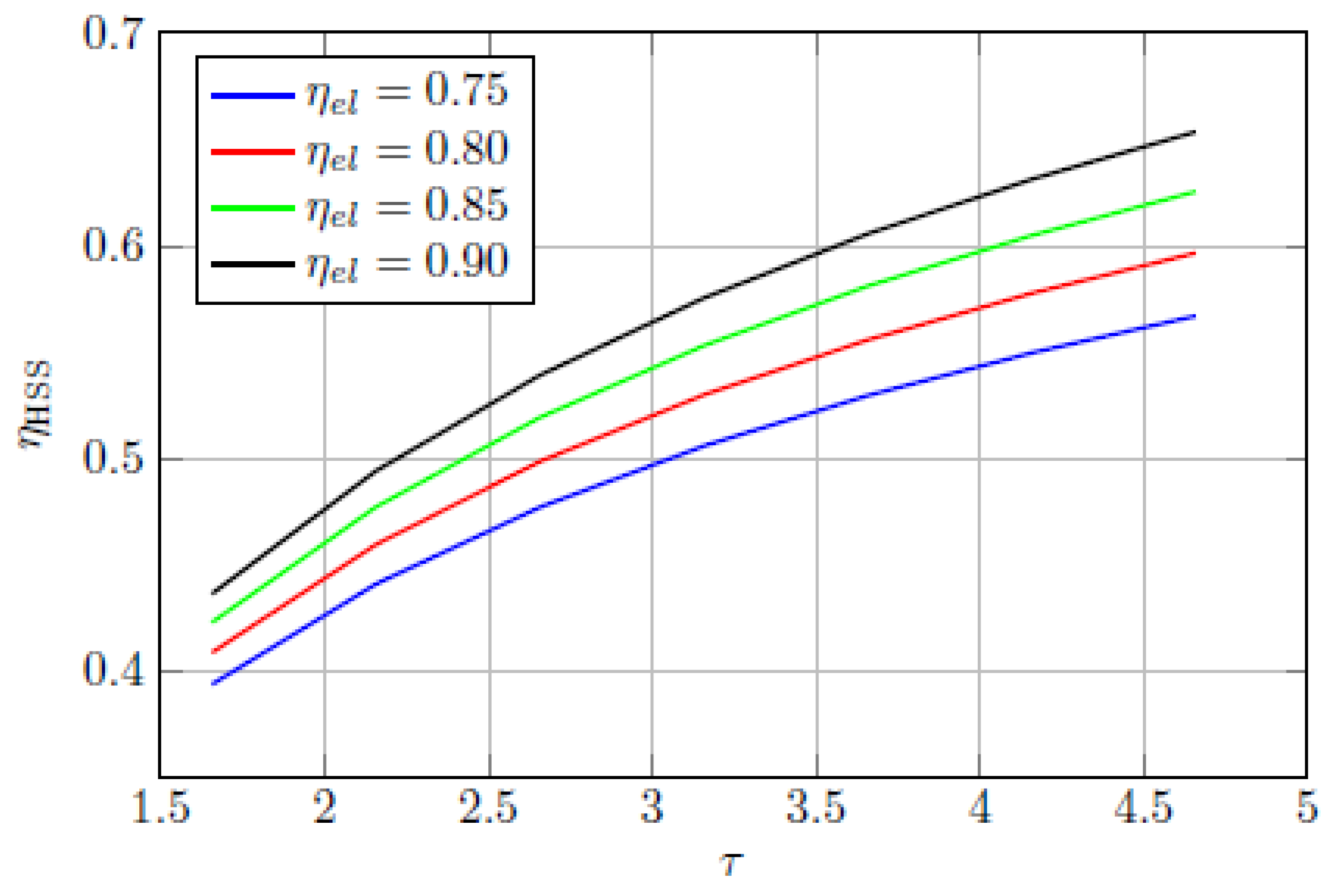
Figure 8 represents ηHSS as a function of τ for different efficiencies of the electrolyzer, ηel. As expected the round-trip efficiency is increased by incrementing ηel, and such an effect is more evident at higher turbine inlet temperatures (i.e., higher values of τ).
4. Conclusions
In this paper, an innovative and effective energy storage system that integrates compressed air and hydrogen technologies has been presented. The main objective has been the system integration necessary to efficiently exploit the different technologies (i.e., electrolyzer, compressor, expander, burner, heat exchangers, etc.) in hybrid storage systems with high round-trip efficiency and zero pollutant emissions.
Different configurations have been investigated, and the main results can be summarized as follows:
- When a simple hybrid storage system is considered, if the heat produced in the compression phase cannot be stored, the introduction of hydrogen storage in a compressed air system is positive.
- When a regenerate system is considered, the combination of hydrogen and compressed air storage always improves the efficiency. The effect of the pressure ratio on the performance of this system is opposite to that of a simple system, as the round-trip efficiency is improved by decreasing βc.
- When a multistage system is considered, the round-trip efficiency increases by increasing the number of stages in both compression and expansion phases. For nc > 3 and/or nt > 3, the marginal increment of efficiency is negligible. We also comment that the system cost is proportional to the number of stages since more fluid machineries and heat exchangers are required. Thereafter, the marginal efficiency improvement has to be balanced with the cost increase. Nevertheless, the energy and employed technology costs are needed for this assessment.
These results demonstrate the compressed air and hydrogen storage system’s effectiveness in improving energy source flexibility and efficiency, and possibly in reducing the costs of energy supply.
An alternative storage configuration based on H2 that allows energy storage without further pollutant emissions is converting the produced hydrogen into power through a fuel cell. The efficiency of such a system would be largely determined by the efficiency of the FC (Fuel Cell) that, depending on the employed technology (proton-exchange membrane, solid oxide, phosphoric-acid, etc.), ranges between 35% and 55% [57,58]. Such an efficiency should also be reduced by the electroliser efficiency. We comment that the proposed storage system is potentially more efficient than FC based ones.
The sensitivity analyses here performed are evidence of the most relevant physical parameters affecting the system performance. The proper choice of such parameters (e.g., nc, βc, βt, etc.) is the starting point for the optimization of the single component of the storage plant, such as the compressor, the turbine, or the electrolyzer.
These results also suggest that the optimization of DG system control strategy (i.e., the possibility of optimally determining when the components have to be set on or off or partialized) is a key aspect to effectively meeting all the positive expectations that are placed on distributed generation and energy storage. Such optimization should rely on both the rated performance of the analyzed system and on the performance derating at part load and as function of the variable environmental conditions.
Finally, future work will be devoted to the assessment of plant performance in realistic energy management scenarios. In fact, a proper economic assessment is strictly connected with the effective application, including energy demand, energy cost, and utilization factors. Thereafter, the optimal system configuration might vary as a function of the system application.
Acknowledgments
All sources of funding of the study should be disclosed. Please clearly indicate grants that you have received in support of your research work. Clearly state if you received funds for covering the costs to publish in open access.
Author Contributions
All authors have contributed equally to the idea and the design of the energy storage system layouts. Luca Andreassi and Andrea Luigi Facci developed the thermodynamic model, implemented the numerical code and made the graphs reported in the figures. All authors contributed to the data analysis. Luca Andreassi and Andrea Luigi Facci wrote the paper.
Conflicts of Interest
The authors declare no conflict of interest.
Nomenclature
| Produced hydrogen mass flow rate | kg/s | |
| Inlet mass flow rate | kg/s | |
| Lower heating value of hydrogen | kJ/kg | |
| Electrical power from the grid to drive the compressor | W | |
| Electrical power from the grid to produce H2 from the electrolyzer | W | |
| Electrical power output | W | |
| Environment temperature | K | |
| Compressor outlet temperature | K | |
| Isentropic temperature at the end of the compression | K | |
| Air temperature at the storage outlet | K | |
| Turbine inlet temperature | K | |
| Turbine outlet temperature | K | |
| Isentropic temperature at the end of the expansion | K | |
| Regenerator outlet temperature | K | |
| Average constant pressure specific heat in the generic thermodynamic transformation between i and j | kJ/(kg·K) | |
| Temperature approach on the hot side of the regenerator | K | |
| Compressor pressure ratio | ||
| Turbine pressure ratio | ||
| Combustor efficiency | ||
| Efficiency of the electrolyzer | ||
| Roundtrip efficiency of the hybrid storage system | ||
| Overall efficiency of the compressor | ||
| Overall efficiency of the turbine | ||
| nc | Number of compression stages | |
| ne | Number of expansion stages | |
| R | Air constant | kJ/kg |
| Air–fuel ratio | ||
References
- International Energy Agency (IEA). World Energy Investment 2017. Available online: https://www.iea.org/publications/wei2017/ (accessed on 11 July 2017).
- Ackermann, T.; Andersson, G.; Sder, L. Distributed generation: A definition. Electr. Power Syst. Res. 2001, 57, 195–204. [Google Scholar] [CrossRef]
- Distributed Generation in Liberalised Electricity Markets; International Energy Agency: Paris, France, 2002.
- Ruan, Y.; Liu, Q.; Zhou, W.; Firestone, R.; Gao, W.; Watanabe, T. Optimal option of distributed generation technologies for various commercial buildings. Appl. Energy 2009, 86, 1641–1653. [Google Scholar] [CrossRef]
- Andreassi, L.; Ciminelli, M.; Feola, M.; Ubertini, S. Innovative method for energy management: Modelling and optimal operation of energy systems. Energy Build. 2009, 41, 436–444. [Google Scholar] [CrossRef]
- Andreassi, L.; Ubertini, S. Optimal management of power systems. In Energy Management; Perez, F.M., Ed.; Intech: Rijeka, Primorsko-Goranska, 2010; ISBN 978-953-307-065-0. [Google Scholar]
- Bella, G.; Facci, A.L.; Fumarola, A.; Tribioli, L.; Ubertini, S. Comparison among different CCHP plant configurations with energy flows optimization. In Proceedings of the Third International Conference on Applied Energy, Perugia, Italy, 16–18 May 2011. [Google Scholar]
- Facci, A.L.; Andreassi, L.; Ubertini, S. Optimization of CHCP (combined heat power and cooling) systems operation strategy using dynamic programming. Energy 2014, 66, 387–400. [Google Scholar] [CrossRef]
- Facci, A.L.; Andreassi, L.; Martini, F.; Ubertini, S. Comparing Energy and Cost Optimization in Distributed Energy Systems Management. J. Energy Resour. Technol. 2014, 136. [Google Scholar] [CrossRef]
- Cavallo, A. Controllable and affordable utility-scale electricity from intermittent wind resources and compressed air energy storage (CAES). Energy 2007, 32, 120–127. [Google Scholar] [CrossRef]
- Facci, A.L.; Andreassi, L.; Ubertini, S.; Sciubba, E. Analysis of the Influence of Thermal Energy Storage on the Optimal Management of a Trigeneration Plant. Energy Procedia 2014, 45, 1295–1304. [Google Scholar] [CrossRef]
- Facci, A.L.; Sánchez, D.; Jannelli, E.; Ubertini, S. Trigenerative micro compressed air energy storage: Concept and thermodynamic assessment. Appl. Energy 2015, 158, 243–254. [Google Scholar] [CrossRef]
- Safaei, H.; Aziz, M.J. Thermodynamic Analysis of Three Compressed Air Energy Storage Systems: Conventional, Adiabatic, and Hydrogen-Fueled. Energies 2017, 10, 1020. [Google Scholar] [CrossRef]
- Wang, J.; Lu, K.; Ma, L.; Wang, J.; Dooner, M.; Miao, S.; Li, J.; Wang, D. Overview of Compressed Air Energy Storage and Technology Development. Energies 2017, 10, 991. [Google Scholar] [CrossRef]
- Li, R.; Wang, H.; Yao, E.; Zhang, S. Thermo-Economic Comparison and Parametric Optimizations among Two Compressed Air Energy Storage System Based on Kalina Cycle and ORC. Energies 2017, 10, 15. [Google Scholar] [CrossRef]
- Kim, Y.M.; Favrat, D. Energy and exergy analysis of a micro-compressed air energy storage and air cycle heating and cooling system. Energy 2010, 35, 213–220. [Google Scholar] [CrossRef]
- Najjar, Y.S.H.; Zaamout, M.S. Performance analysis of compressed air energy storage (CAES) plant for dry regions. Energy Convers. Manag. 1998, 39, 1503–1511. [Google Scholar] [CrossRef]
- Sharma, A.; Chiu, H.H.; Ahrens, F.W.; Ahluwalia, R.K.; Ragsdell, K.M. Design of optimum compressed air energy-storage systems. Energy 1979, 4, 201–216. [Google Scholar] [CrossRef]
- Giramonti, A.J.; Lessard, R.D.; Blecher, W.A.; Smith, E.B. Conceptual design of compressed air energy storage electric power systems. Appl. Energy 1978, 4, 231–249. [Google Scholar] [CrossRef]
- Glendenning, I. Long-term prospects for compressed air storage. Appl. Energy 1976, 2, 39–56. [Google Scholar] [CrossRef]
- Briola, S.; Di Marco, P.; Gabbrielli, R.; Riccardi, J. Sensitivity analysis for the energy performance assessment of hybrid compressed air energy storage systems. Appl. Energy 2017, 206, 1552–1563. [Google Scholar] [CrossRef]
- Lund, H.; Salgi, G. The role of compressed air energy storage (CAES) in future sustainable energy systems. Energy Convers. Manag. 2009, 50, 1172–1179. [Google Scholar] [CrossRef]
- Momirlan, M.; Veziroglu, T.N. The properties of hydrogen as fuel tomorrow in sustainable energy system for a cleaner planet. Int. J. Hydrog. Energy 2005, 30, 795–802. [Google Scholar] [CrossRef]
- Pike Research’s “Energy Storage Tracker”. Available online: http://energystoragereport.info/tag/pike-research/ (accessed on 29 November 2017).
- Lux Research Inc. Grid Storage under the Microscope: Using Local Knowledge to Forecast Global Demand; Report No. LRSGI-R-11-1; Lux Research Inc.: Boston, MA, USA, 2012. [Google Scholar]
- Succar, S.; Williams, R.H. Compressed Air Energy Storage: Theory, Resources and Applications for Wind Power; Princeton Environmental Institute: Princeton, NJ, USA, 2008. [Google Scholar]
- European Commission. A Roadmap for moving to a competitive low carbon economy in 2050. Communication from the Commission to the European Parliament, the Council, the European Economic and Social Committee and the Committee of the Regions. Available online: http://eur-lex.europa.eu/legal-content/EN/TXT/PDF/?uri=CELEX:52011DC0112&from=EN. (accessed on 29 September 2017).
- International Energy Agency. World Energy Outlook 2010; International Energy Agency: Paris, France, 2010. [Google Scholar]
- DOE Global Energy Storage Database. Available online: http://www.energystorageexchange.org/ (accessed on 15 September 2017).
- Eckard, R. CAES Compressed Air Energy Storage Worldwide; SBI Energy: Rockville, MD, USA, 2010. [Google Scholar]
- Cazzaniga, R.; Cicu, M.; Rosa-Clot, M.; Ventura, C. Compressed air energy storage integrated with floating photovoltaic plant. J. Energy Storage 2017, 13, 48–57. [Google Scholar] [CrossRef]
- Chen, L.X.; Hu, P.; Sheng, C.C.; Xie, M.N. A novel compressed air energy storage (CAES) system combined with pre-cooler and using low grade waste heat as heat source. Energy 2017, 131, 259–266. [Google Scholar] [CrossRef]
- Kim, Y.M.; Lee, J.H.; Kim, S.J.; Favrat, D. Potential and evolution of compressed air energy storage: Energy and exergy analyses. Entropy 2012, 14, 1501–1521. [Google Scholar] [CrossRef]
- Krawczyk, P.; Szablowski, L.; Karellas, S.; Badyda, K. Comparative thermodynamic analysis of compressed air and liquid air energy storage systems. Energy 2018, 142, 46–54. [Google Scholar] [CrossRef]
- Briola, S.; Di Marco, P.; Gabbrielli, R.; Riccardi, J. A novel mathematical model for the performance assessment of diabatic compressed air energy storage systems including the turbomachinery characteristic curves. Appl. Energy 2016, 178, 758–773. [Google Scholar] [CrossRef]
- Szablowski, L.; Krawczyk, P.; Badyda, K.; Bujalski, W. Energy and exergy analysis of adiabatic compressed air energy storage system. Energy 2017, 138, 12–18. [Google Scholar] [CrossRef]
- Bullough, C.; Gatzen, C.; Jakiel, C.; Koller, M.; Nowi, A.; Zunft, S. Advanced adiabatic compressed air energy storage for the integration of wind Energy. In Proceedings of the European Wind Energy Conference, EWEC 2004, London, UK, 22–25 November 2004. [Google Scholar]
- Ibrahim, H.; Ilinca, A.; Perron, J. Energy storage systems—Characteristics and comparisons. Renew. Sustain. Energy Rev. 2008, 12, 1221–1250. [Google Scholar] [CrossRef]
- Vadasz, P. Compressed air energy storage: Optimal performance and technoeconomical indices. Int. J. Appl. Thermodyn. 1999, 2, 69–80. [Google Scholar]
- Yoshimoto, K.; Nanahara, T. Optimal daily operation of electric power systems with an ACC-CAES generating system. Electr. Eng. Jpn. 2005, 152, 15–23. [Google Scholar] [CrossRef]
- Lund, H.; Salgi, G.; Elmegaard, B.; Andersen, N. Optimal operation strategies of compressed air energy storage (CAES) on electricity spot markets with fluctuating prices. Appl. Therm. Eng. 2009, 29, 799–806. [Google Scholar] [CrossRef]
- Greenblatt, J.B.; Succar, S.; Denkenberger, D.; Williams, R.; Socolow, R. Baseload wind energy: Modeling the competition between gas turbines and compressed air energy storage for supplemental generation. Energy Policy 2007, 35, 1474–1492. [Google Scholar] [CrossRef]
- Grazzini, G.; Milazzo, A. Thermodynamic analysis of CAES/TES systems for renewable energy plants. Renew. Energy 2008, 33, 1998–2006. [Google Scholar] [CrossRef]
- Todd, D.M.; Battista, R.A. Demonstrated Applicability of Hydrogen Fuel for Gas Turbines—GE Power Systems; National Energy Technology Laboratory: Noordwijk, The Netherlands, 2009.
- Barbir, F. PEM electrolysis for production of hydrogen from renewable energy sources. Sol. Energy 2005, 78, 661–669. [Google Scholar] [CrossRef]
- Badwal, S.P.S.; Giddey, S.; Ciacchi, F.T. Hydrogen and oxygen generation with polymer electrolyte membrane (PEM) based electrolytic technology. Ionics 2006, 12, 7–14. [Google Scholar] [CrossRef]
- Millet, P.; Andolfatto, F.; Durand, R. Design and performance of a solid polymer electrolyte water electrolyser. Int. J. Hydrog. Energy 1996, 21, 87–93. [Google Scholar] [CrossRef]
- Newborough, M.A. Report on Electrolyzers, Future Markets and the Prospects for ITM Power Ltd’s Electrolyser Technology. 2004. Available online: http://www.h2fc.com/Newsletter/PDF/electrolyserTechnologyReportFINAL.doc (accessed on 29 November 2017).
- Andrews, J.; Mohammadi, S.S. Towards a ‘proton flow battery’: Investigation of a reversible PEM fuel cell with integrated metal-hydride hydrogen storage. Int. J. Hydrog. Energy 2014, 39, 1740–1751. [Google Scholar] [CrossRef]
- Padin, J.; Veziroglu, T.N.; Shahin, A. Hybrid solar hightemperature hydrogen production system. Int. J. Hydrog. Energy 2000, 25, 295–317. [Google Scholar] [CrossRef]
- Lehman, P.A.; Chamberlin, C.E.; Rocheleau, P. Operating experience with a photovoltaic-hydrogen energy system. Int. J. Hydrog. Energy 1997, 22, 465–470. [Google Scholar] [CrossRef]
- Ghosh, P.C.; Emont, B.; Janben, H.; Mergel, J.; Stolten, D. Ten years of operational experience with a hydrogen-based renewable energy supply system. Sol. Energy 2003, 75, 469–478. [Google Scholar] [CrossRef]
- Szyszka, A. Ten years of solar hydrogen demonstration project at Neunburg Vorm Wald, Germany. Int. J. Hydrog. Energy 1998, 23, 849–860. [Google Scholar] [CrossRef]
- Hollmuller, P.; Joubert, J.M.; Lachal, B.; Yvon, K. Evaluation of a 5 kWp photovoltaic hydrogen production and storage installation for a residential home in Switzerland. Int. J. Hydrog. Energy 2000, 25, 97–109. [Google Scholar] [CrossRef]
- Agbossou, K.; Chahine, R.; Hamelin, J.; Laurencelle, F.; Anouar, A.; Starnaud, J.M.; Bose, T.K. Renewable energy system based on hydrogen for remote applications. J. Power Sour. 2001, 96, 168–172. [Google Scholar] [CrossRef]
- Gokcen, N.A.; Reddy, R.G. Thermodynamics; Plenum Press: New York, NY, USA; London, UK, 1996. [Google Scholar]
- Facci, A.L.; Cigolotti, V.; Jannelli, E.; Ubertini, S. Technical and economic assessment of a SOFC-based energy system for combined cooling, heating and power. Appl. Energy 2017, 192, 563–574. [Google Scholar] [CrossRef]
- Cappa, F.; Facci, A.L.; Ubertini, S. Proton exchange membrane fuel cell for cooperating households: A convenient combined heat and power solution for residential applications. Energy 2015, 90, 1229–1238. [Google Scholar] [CrossRef]
Figure 1.
Schematic representation of the simple hybrid energy storage system.

Figure 2.
Efficiency of the hybrid storage system (HSS) as a function of τ for different values of βc from 20 to 40. The plot refers to a system with ξ = 0.8 (left) and ξ = 0.6 (right), βe = 0.9 * βc, ηel = 0.80, ηt = 0.9, ηc = 0.9, and ηcc = 0.98. For the selected range of βc, 0.42 < ξ < 1.
Figure 2.
Efficiency of the hybrid storage system (HSS) as a function of τ for different values of βc from 20 to 40. The plot refers to a system with ξ = 0.8 (left) and ξ = 0.6 (right), βe = 0.9 * βc, ηel = 0.80, ηt = 0.9, ηc = 0.9, and ηcc = 0.98. For the selected range of βc, 0.42 < ξ < 1.

Figure 3.
Regenerated hybrid storage system.

Figure 4.
Efficiency of the regenerated HSS system as a function of τ for different values of βc. The plot refers to a system with ξ = 0.5, βe = 0.9 * βc, = 0.80, ηt = 0.9, ηc = 0.9, and ηcc = 0.98.
Figure 4.
Efficiency of the regenerated HSS system as a function of τ for different values of βc. The plot refers to a system with ξ = 0.5, βe = 0.9 * βc, = 0.80, ηt = 0.9, ηc = 0.9, and ηcc = 0.98.

Figure 5.
Efficiency of the regenerated HSS system as a function of τ for different values of ξ in the range of 0.53 to 0.83. The plot refers to a system with βc = 20, βe = 0.9 * βc, ηel = 0.80, ηt = 0.9, ηc = 0.9, and ηcc = 0.98.
Figure 5.
Efficiency of the regenerated HSS system as a function of τ for different values of ξ in the range of 0.53 to 0.83. The plot refers to a system with βc = 20, βe = 0.9 * βc, ηel = 0.80, ηt = 0.9, ηc = 0.9, and ηcc = 0.98.

Figure 6.
Hybrid storage system with regeneration, intercooled compression, and reheated expansion.

Figure 7.
Efficiency of the multistage HSS system as a function of τ with a single stage of expansion for different stages of compression, nc, from 1 to 4 (a) and with two stages of compression for different stages of expansion, nt, from 1 to 4 (b). The plot refers to a system, βc = 20, βe = 0.9 * βc, ηel = 0.80, ηt = 0.9, ηc = 0.9, and ηcc = 0.98.

Figure 8.
Efficiency of the multistage HSS system as a function of τ for different values of the electrolyzer efficiency from 0.7 to 0.9. The plot refers to a system with three stages of compression and three stages of expansion, βc = 20, βe = 0.9 * βc, ηel = 0.80, ηt = 0.9, ηc = 0.9, and ηcc = 0.98.

© 2017 by the authors. Licensee MDPI, Basel, Switzerland. This article is an open access article distributed under the terms and conditions of the Creative Commons Attribution (CC BY) license (http://creativecommons.org/licenses/by/4.0/).
Share and Cite
MDPI and ACS Style
Ubertini, S.; Facci, A.L.; Andreassi, L. Hybrid Hydrogen and Mechanical Distributed Energy Storage. Energies 2017, 10, 2035. https://doi.org/10.3390/en10122035
AMA Style
Ubertini S, Facci AL, Andreassi L. Hybrid Hydrogen and Mechanical Distributed Energy Storage. Energies. 2017; 10(12):2035. https://doi.org/10.3390/en10122035
Chicago/Turabian StyleUbertini, Stefano, Andrea Luigi Facci, and Luca Andreassi. 2017. "Hybrid Hydrogen and Mechanical Distributed Energy Storage" Energies 10, no. 12: 2035. https://doi.org/10.3390/en10122035
Note that from the first issue of 2016, this journal uses article numbers instead of page numbers. See further details here.