Experimental Evaluation of a Switching Matrix Applied in a Bank of Supercapacitors
by
 ,
,
Maria Guadalupe Reveles-Miranda
1,†,‡ ,
,
Manuel Israel Flota-Bañuelos
2,†,‡,
Freddy Chan-Puc
3,†,‡ and
Daniella Pacheco-Catalán
1,*,†,‡
1
Renewable Energy Unit, Yucatan Center for Scientific Research, Merida 97205, Yucatan, Mexico
2
Engineering Department, University of Yucatan, Merida 97000, Yucatan, Mexico
3
Engineering Department, University of Quintana Roo, Chetumal 77019, Quintana Roo, Mexico
*
Author to whom correspondence should be addressed.
†
Current address: Carr. Sierra Papacal-Chuburná Puerto, km 5. Sierra Papacal, Merida 97205, Yucatan, Mexico.
‡
These authors contributed equally to this work.
Energies 2017, 10(12), 2077; https://doi.org/10.3390/en10122077
Submission received: 19 October 2017
/
Revised: 23 November 2017
/
Accepted: 28 November 2017
/
Published: 7 December 2017
(This article belongs to the Section D: Energy Storage and Application)
Abstract
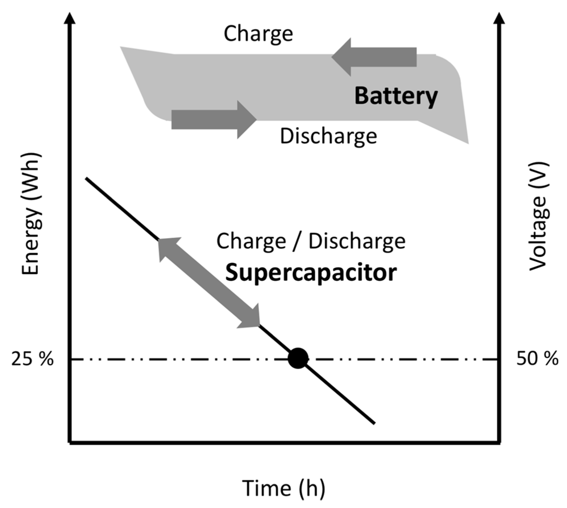
:Distributed power generation systems (DPGSs) integrate power sources that tend to be smaller than the typical utility scale, such as for renewable energy sources and other applications. Storage systems that incorporate supercapacitors (SCs) have been proposed to extend the life of batteries and to increase the power capacity of the DPGSs, guaranteeing maximum efficiency. The extraction of energy in SCs is more demanding than in the case of batteries; when SCs have delivered only 75% of their energy, their voltage has already decreased to 50%. Beyond this value, the banks fail to meet the requirements demanded by loads that require a minimum voltage to operate correctly, leaving 25% of the energy unused, thereby limiting the deep charge/discharge cycles that occur. This paper presents a model of a switching matrix applied in a bank of SCs. The model allows the use of a simpler circuit to achieve a large number of serial/parallel-configuration connections (levels), improving the utilization of energy to obtain deep discharge cycles in each SC; therefore, by increasing the average energy extracted from each SC, it extends the power delivery time in the storage bank. The efficiency was verified by experimental results obtained using a bank of six SCs.
1. Introduction
Distributed power generation systems (DPGSs) are smaller power sources that can be aggregated to provide the power necessary to meet regular demand on the utility grid. As the electricity grid continues to modernize, DPGSs, such as storage and advanced renewable technologies, can help facilitate the transition to a smarter grid. Many DPGSs have DC output: batteries, supercapacitors (SCs), photovoltaic cells, fuel cells, wind turbines, micro hydro generators, and small fossil fuel generators. Different power converter topologies have been developed to connect DPGSs to the utility grid [1]. The principal objectives when selecting a topology include increasing efficiency, increasing reliability, reducing the output current and voltage harmonics, decreasing the size, and reducing the cost [2]. The use of a storage system with a fast dynamic is necessary for many applications; the supercapacitor (SC) is a device that ensures the efficient management between the intermittently generated power and the consumer demand and increases the performance of the DPGSs [3]. The SC has a higher power density, longer life cycle, and higher discharging/charging efficiency than a battery. Also, the SC has a faster charging time, a broader temperature window of operation, and a lower internal resistance [4]. However, due to their low power density, they report a maximum energy utilization efficiency only of the 75% [5]. For all these reasons, SCs are connected in banks to take advantage of their characteristics in energy storage, and to contribute to the stability of the power system with a distributed resource where high peak power demand is necessary [6].
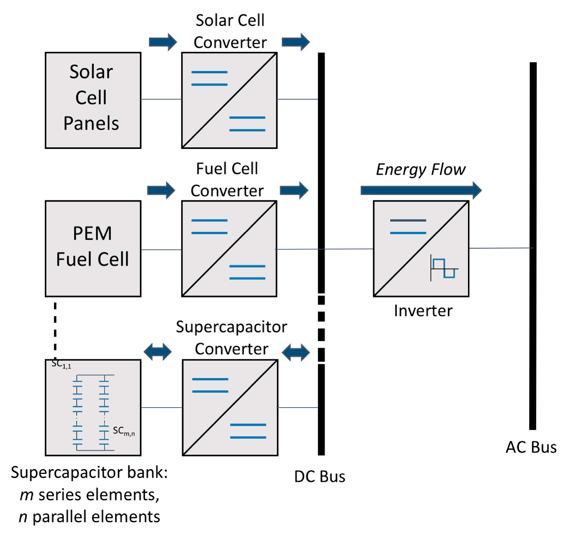
A model using an SC bank (SCB) connected to a solar panel was studied to compensate the power fluctuation of the power generation. This configuration provides a power allocation strategy for the intermittency of wind power fluctuations [7]. When an SCB is employed in a DPGSs system, a bidirectional DC/DC power converter is necessary to limit the DC voltage fluctuations between the capacitor bank and the DC/AC converter connected to the utility grid (Figure 1) [8]. For this reason, topologies for connecting an SCB to the DC/DC converters were analyzed. The DC/DC converter maintains a constant voltage on the DC bus, even though the terminal voltage of the SCB varies. However, the use of a bidirectional DC/DC converter involves a doubling of processing power. In the process of charging and discharging the SCB, there are energy losses in the converter. Due to the doubled processing power in the bidirectional DC/DC converter, the overall efficiency is reduced. Therefore, the requirements in the DC inductors are increased in the case of fast charging/discharging, and complex control with other converters [9]. There is a need for inductors and a transformer in DC/DC converters. The practical implementation of magnetic-core components involves such negatives as saturation core and copper losses, nonlinearity, weight, bulk and cost, and unreliable availability. Because an SC is also an energy storage device, it is only natural to ponder the possibility of substituting inductors for SCs; while direct substitution is not feasible, circuits can be devised to exploit the energy-storage nature of the SCs.
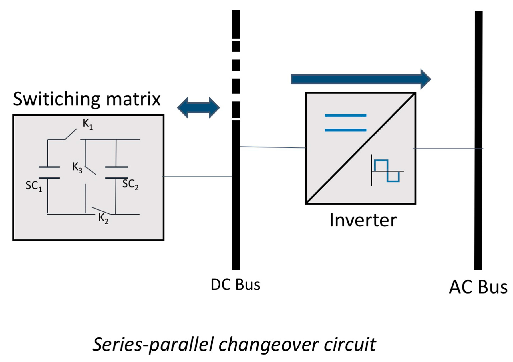
A series/parallel changeover circuit (Figure 2) was proposed as a simple option [10,11,12]. The connection between the SCs of an SCB depends on the properties and requirements of the system in which it is used. Series connection increases the voltage level and provides a power supply suitable to more robust applications with major electrical power requirements [10]. Nevertheless, due to the non-uniform properties of all series/connected cells, it causes a small imbalance in the continual charge and discharge process due to the various voltages present in every cell [13]. A parallel connection is typically used in applications that a require high current for operation; this connection increases the storage capacity by adding to the total ampere-hours (Ah) and controlling the voltage range [14]. One factor to consider in the connection between the SCs of the bank is the fact that the voltage in the power terminals of the bank varies according to the stored energy. Extraction of energy in an SC is more demanding than in the case of batteries; when they have supplied nearly 100% of their energy, their voltage decreases to only 80%; whereas when the SCs have delivered only 75% of their energy, their voltage drops to 50%. Under these conditions, the banks fail to meet the requirements demanded by loads that require a minimum voltage to operate correctly; that 25% remains as available energy, thereby limiting the occurrence of its deep charge/discharge cycle (Figure 3) [15]. In the case of using SCs for energy storage, efficient power conversion electronics are required, with which the SCs can be discharged as efficiently and deeply as possible (i.e., a high average energy extraction of SCs [16]). The efficiency of SC modules is a parameter directly related to the energy extraction. The SC must be discharged as much as possible to obtain a higher extraction of the stored energy. The energy extraction of the SCs () is defined by the ratio of the initial energy () of the module, and the residual energy () [17]:
where and are given by:
where is the capacitance of SCs, corresponds to the initial voltage of the module and is the residual voltage after the discharge, while the average efficiency is given by [16]:
where is the discharged energy or total energy used.
The SC may be used to complete the electrical power capacity of batteries in numerous applications. They can be used to store energy and provide peak power demands in power electronic systems [18]. All of this is to optimize the battery lifetime and provide a very high cycle efficiency for various charge and discharge requests, if favorable loading conditions are provided [19].
With the addition of SCs to batteries, many advantages can be realized: (1) improvement of the lifetime; (2) reduction of size and cost; (3) reduction in stress; and (4) improvement in the power balance between the generation and the load demand [20].
For this reason, energy extraction techniques for the banks are still in development, and the implementation of capacitor self-reconfiguration in battery management systems has been extensively studied for energy transfer components and voltage equalizer applications [21,22]. With the aim of taking advantage of the characteristics of the SC, one of the alternatives in energy storage is the self-reconfiguration of the connections between the SCs that make up the storage bank. The changeover of the series/parallel connection in the SCB increases the energy utilization efficiency of each device, and improves the utilization of the energy stored, decreasing the rate of voltage fluctuations in the banks. Due to their being maintenance-free and having a long lifetime, SCBs can be employed to absorb input power fluctuations in a power system, thus ensuring power quality; additionally, this strongly favors their application in uninterruptible power supplies (UPS) and other energy storage devices. A set of eight SCs with four flexible series/parallel reconfigurations for the discharge cycle was presented, with an overall efficiency of 93% and an average power draw factor of 83%. However, the extraction in each SC was variable, and so did not provide deep charge/discharge cycles, in each device [23].
In other work, a set of six SCs with two reconfigurations was presented, but without obtaining a deep charge/discharge, as it only reported an 80.6% energy factor extraction for each SC, with a voltage variation rate of 36% [17]. Nevertheless, due to the diversity of the energy sources and the nature of the charge feed, this was a reconfigurable system that provided flexibility for a power generation system.
Distributed generation systems require control that permits the optimal management of the energy generated. Therefore, with the new simplified model of a basic switching cell for SCBs proposed here, it can feasibly be used in more complex systems such as smart grids [24,25,26] and hybrid power production units [3,27].
2. Switching Matrix
Since the voltage density and power of an SC is low, it usually requires a series/parallel system reconfiguration for the SCB. A basic switching cell BSC has previously been proposed, which allows the reconnection of the SC [28]. This system requires three control signals for each switching cell (Figure 4). Cells of two or more levels have been proposed for handling a large number of SCs with a variety of series/parallel configurations. However, the number of control signals increased, requiring up to five control signals for a bank of two levels [29]. In another work, a proposed three-level cell required 12 control signals [30]. In this study, the analysis of a storage bank with programmed discharge for the series/parallel changeover of six SCs () is presented. Figure 5 shows the connection circuit for the switching matrix. In this case, it was possible to obtain a simplified model for the matrix with three switching states () and its complement (). The series/parallel changeover was dependent on the output voltage level of the bank, and this feature connection could be extrapolated to larger arrays. The proposed reconfigurations were based on the number of devices to increase the energy delivery time of the storage bank to a constant voltage level within a set interval to ensure a uniform energy extraction from each SC with deep charge/discharge cycles. The electric circuits connecting the SCs in each reconfiguration and programmed state of the storage device are shown in Table 1.
3. Operation Principle Analysis
The charge of the storage bank was conducted with the SCs connected in parallel for a faster charge in Table 1. For this reason, the discharge with the devices connected in parallel when the output voltage of the bank () was less than or equal to the value of the first reconfiguration voltage reference (), and the SCs were reconfigured into three parallel groups of two devices in series. The voltage available in the SC is generated so that the voltage of the bank increases instantaneously and continues the discharge; when is less than or equal to the second programmed switching voltage (), the connection between the SCs is reconfigured into two parallel groups of three series devices. The voltage of the bank increases instantaneously again and continues with the discharge of the bank; when is less than or equal to the third programmed switching voltage () the signal is sent to the ports required to reconfigure the connection to six cells in series.
Therefore, the voltage increases again and continues the discharge of the bank; finally, when the output voltage of the is less than or equal to the fourth programmed switching voltage (). the connection is reconfigured to have all the SCs in parallel, terminating the discharge cycle and starting the charge cycle. In addition to the changeover, four routines with different voltage levels () are also proposed for each series/parallel changeover of the SCB () by considering the number of devices that make up the storage device and its uniform extraction of energy to obtain deep discharge cycles. Finally, the voltage delivery time of the module is increased.
4. Experimental Results
The electrical characterization was undertaken with data acquired from the charge/discharge test, which were performed with six SC IC107DCN2R7Q (100 F − 2.7 V); a resistor at 4.7 Ω was used to limit the charge current of the SCs. The discharge was performed using a resistance of 3.7 Ω. The voltage supply of the SCs was 1.0 V, and the switching circuit was 12.0 V, which was powered by the DC GW power supplies Instek GPS-3303. The energy values reported were calculated by reading the bank voltage and SC voltage with a Agilent 34970A data acquisition unit. LabVIEW was used as the data measurement and recording platform; Figure 8 shows the test bank.
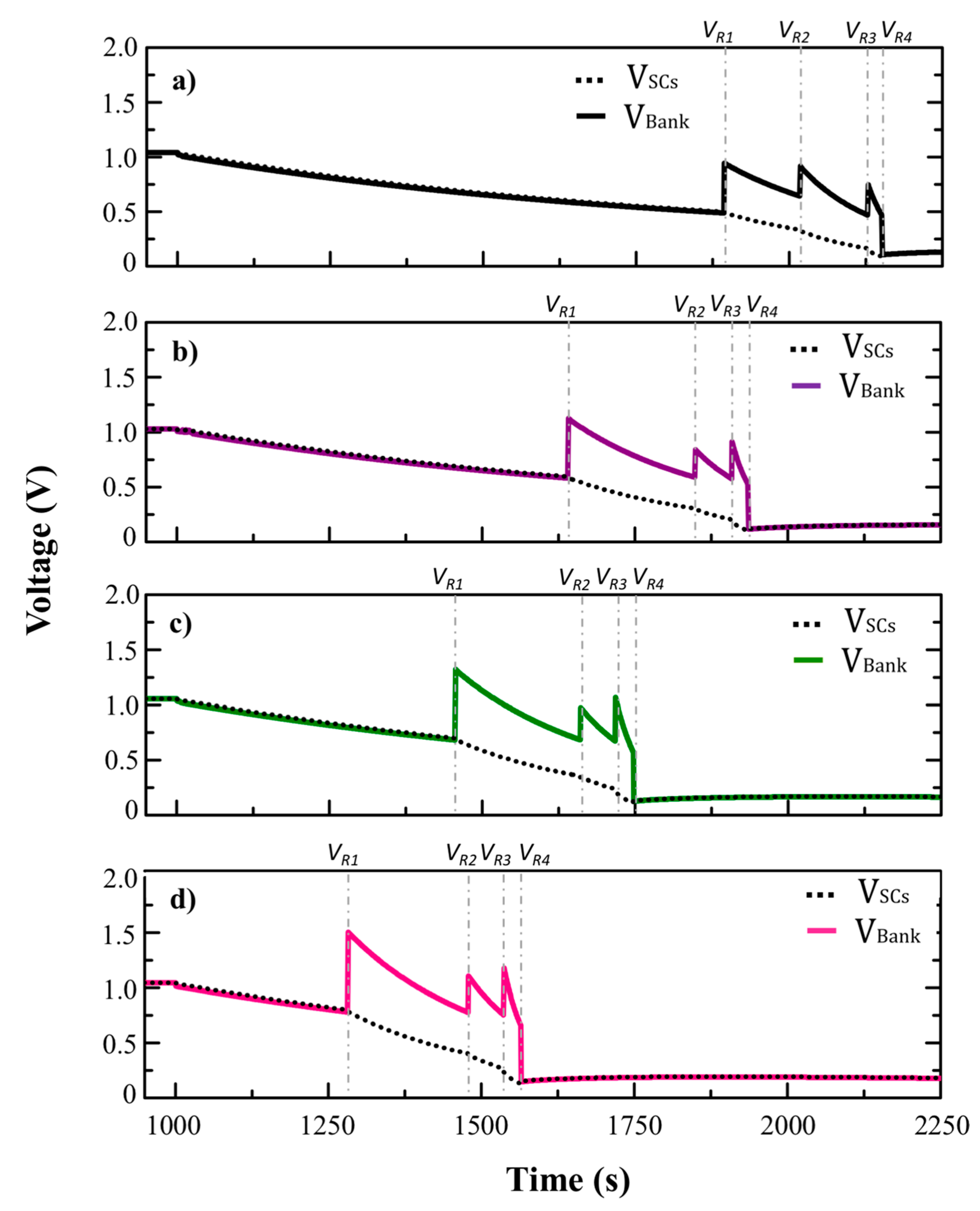
Figure 9 shows the discharge of the SCB for each discharge routine obtained from the electrical characterization and the average value of energy present in each device, as well as presenting the complete bank during each of the reconfigurations. The reconfiguration of the bank voltage (), as well as the period between each reconfiguration, can be observed. The increase in the voltage peaks corroborated the execution of each of the proposed reconfigurations. The average voltage level () present in the six SCs at the time of each reconfiguration is displayed by the dashed line. Each of the proposed reconfigurations increased the voltage delivery time within the functional range to meet the requirements demanded by loads that require a minimum voltage to operate correctly. It can be seen from Figure 9 that the higher the voltage value of the reconfiguration, the greater the level of tension obtained in the output of the SCB. The slope of each discharge process is different, because the reconfiguration voltage value in each respective routine is not equal, while the higher the reconfiguration voltage limit, the longer the percentage time increment, and due to this, the original discharge time is shorter, and therefore represents the most significant increase of time. The choice of an appropriate reconfiguration routine is dependent on the application and its voltage requirements. In all cases, however, the reconfiguration increased the energy delivery time of the storage device.
The state changes occurred at voltage levels , which are indicated in the graphs. The surge in bank profile indicates the carrying out of each reconfiguration. With a simpler switching matrix, more reconfigurations were obtained than those reported in reference [5]. It can be seen from Figure 9 that, as the available energy decreased, the device discharged faster, as the extraction of energy from the SCs demands a greater voltage drop than batteries.
From the performance of each proposed routine, the discharge time of the bank and the percentage increment was obtained. In Table 3, the increase in time of the programmed routines displays progressive behavior, in which the higher the reconfiguration voltage limit, the longer the time increment. Due to this, the original download time was smaller, therefore representing the most significant increase in time. The percentage increase obtained was similar to that reported in reference [23] under different reconfiguration conditions and with a smaller number of devices.
The extra energy values obtained in each reconfiguration routine indicated that as the reconfiguration limit was raised, the average energy decreased and the extra energy that could be obtained increased. Due to the higher voltage value in the reconfiguration, there was more energy to be drawn from each SC. It has been reported that SCs have approximately charge/discharge cycles, with an energy extraction of 75% per cycle. The deep discharge cycle is a parameter directly related to the life cycle of storage devices; in the SC, a partial discharge affects its level of efficiency in the long term, which is the reason why a deep discharge will ensure an optimal operation of the device for a longer time [31].
Despite its low energy density, the reconfiguration routines guarantee greater extraction of the energy available in the SC. With the proposed reconfiguration routines, up to 23% more energy was extracted per cycle. This increase in the extraction of the total available energy was equivalent to 30% more energy used during useful life compared to a device that was not reconfigured. The SCs were discharged to approximately 0.13 V, which is what determines the energy utilization ratio calculated by (1). Figure 10 shows the average values of the energy extracted from each routine, where high average values of extraction energy were obtained. The average energy extraction varied between 97.13% and 98.87%; 18% higher than the 83.3% and 83.1% reported by references [10,17], respectively. This result represents an equitable and efficient use of the energy of each SC, with deeper cycles of charge/discharge on each device.
In the case of module efficiency with the proposed reconfiguration routines, the efficiency average was calculated by (4). In Table 4, it can be observed that the average was 99%; high efficiency and high utilization ratios of SCs can be achieved without advanced switching techniques, and at variable voltage outputs. The efficiency of the bank changeover circuit was similar, at 99%, to that reported by [23], and greater than the 91.4 % and 94% reported by [16,32].
The switching matrix improves the extraction of average energy in an SC bank and increases the reliability of the DPGSs; however, for the interconnection with the DC bus, the incorporation of a unidirectional DC/DC converter that reduces the voltage variations during the SCs’ discharging process could be necessary. Since the initial objective was to avoid the doubled energy processing of the bidirectional DC/DC converter, the switching matrix avoids the need for processing during the SC bank charging process, increasing the overall efficiency of the system with this action. In practice, the energy losses are significantly reduced by the appropriate selection of charging and discharging cycles, and by the relative sizes of the capacitors involved. If the replenishment and transfer of charge occur repetitively, the energy loss can be is least; however, this action must not be done at too high a rate, because the high switching rates serve only to degrade the efficiency of the process.
5. Conclusions
A switching matrix applied to reconfiguring an SC bank was experimentally evaluated. The proposed matrix is a simple circuit that achieves four configurations through series/parallel connections. The average energy extracted was increased to 98.87%. The discharge patterns show that the proposed reconfigurations increase the discharging time in all cases. Energy extraction is dependent on the reconfiguration voltage; this extraction decreases when the voltage increase.
Acknowledgments
The authors would like to thank M.C. Enrique Escobedo for technical support. This work was supported by CONACYT-SENER No. 254667, CICY and PRODEP: DSA/103.5/15/14192.
Author Contributions
Freddy Chan-Puc, Manuel Israel Flota-Bañuelos and Daniella Pacheco-Catalán conceptualize the idea of this research project. Maria Guadalupe Reveles-Miranda was responsible for experiment and writing. Freddy Chan-Puc provides an experimental setup. Manuel Israel Flota-Bañuelos and Daniella Pacheco-Catalán contributed to the article revision, and Daniella Pacheco-Catalán provide the funding support.
Conflicts of Interest
The authors declare no conflict of interest. The founding sponsors had no role in the design of the study; in the collection, analyses, or interpretation of data; in the writing of the manuscript, and in the decision to publish the results.
References
- Blaabjerg, F.; Yang, Y.; Yang, D.; Wang, X. Distributed Power-Generation Systems and Protection. Proc. IEEE 2017, 105, 1311–1331. [Google Scholar] [CrossRef]
- Wu, T.-F.; Chang, C.-H.; Lin, L.-C.; Kuo, C.-L. Power Loss Comparison of Single- and Two-Stage Grid-Connected Photovoltaic Systems. IEEE Trans. Energy Convers. 2011, 26, 707–715. [Google Scholar] [CrossRef]
- Abdelkafi, A.; Krichen, L. Energy management optimization of a hybrid power production unit based renewable energies. Int. J. Electr. Power Energy Syst. 2014, 62, 1–9. [Google Scholar] [CrossRef]
- Li, L.; Huang, Z.; Li, H.; Peng, J. A rapid cell voltage balancing scheme for supercapacitor based energy storage systems for urban rail vehicles. Electr. Power Syst. Res. 2017, 142, 329–340. [Google Scholar] [CrossRef]
- Nie, J.-F.; Xiao, X.; Nie, Z.; Tian, P.; Ding, R. A novel three-level changeover circuit of super-capacitor bank for energy storage systems. In Proceedings of the 38th Annual Conference on IEEE Industrial Electronics Society (IECON 2012), Montreal, QC, Canada, 25–28 October 2012; pp. 144–149. [Google Scholar]
- Sathishkumar, P.; Piao, S.; Khan, M.; Kim, D.-H.; Kim, M.-S.; Jeong, D.-K.; Lee, C.; Kim, H.-J. A Blended SPS-ESPS Control DAB-IBDC Converter for a Standalone Solar Power System. Energies 2017, 10, 1431. [Google Scholar] [CrossRef]
- Liu, J.; Zhang, L. Strategy Design of Hybrid Energy Storage System for Smoothing Wind Power Fluctuations. Energies 2016, 9, 991. [Google Scholar] [CrossRef]
- Ibanez, F.M.; Echeverria, J.M.; Vadillo, J.; Fontan, L. A Step-Up Bidirectional Series Resonant DC/DC Converter Using a Continuous Current Mode. IEEE Trans. Power Electron. 2015, 30, 1393–1402. [Google Scholar] [CrossRef]
- Azib, T.; Bethoux, O.; Remy, G.; Marchand, C.; Berthelot, E. An innovative control strategy of a single converter for hybrid fuel cell/supercapacitor power source. IEEE Trans. Ind. Electron. 2010, 57, 4024–4031. [Google Scholar] [CrossRef]
- Uno, M.; Tanaka, K. Single-switch single-inductor equalization charger using a voltage multiplier for series-connected energy storage modules. In Proceedings of the 2011 IEEE 8th International Conference on Power Electronics and ECCE Asia (ICPE & ECCE), Jeju, Korea, 30 May–3 June 2011; pp. 2985–2989. [Google Scholar] [CrossRef]
- Zhang, E.; Qi, Z.; Wei, T. Research on combination of series and parallel with supercapacitor module. In Proceedings of the 2010 2nd IEEE International Symposium on Power Electronics for Distributed Generation Systems (PEDG), Hefei, China, 16–18 June 2010; pp. 685–690. [Google Scholar] [CrossRef]
- Srithorn, P.; Aten, M.; Parashar, R. Series connection of supercapacitor modules for energy storage. In Proceedings of the 3rd IET International Conference on Power Electronics, Machines and Drives (PEMD 2006), Dublin, Ireland, 4–6 April 2006; Volume 2006, pp. 354–360. [Google Scholar]
- Chatzakis, J.; Kalaitzakis, K.; Voulgaris, N.C.; Manias, S.N. Designing a new generalized battery management system. IEEE Trans. Ind. Electron. 2003, 50, 990–999. [Google Scholar] [CrossRef]
- Yuhimenko, V.; Averbukh, M.; Agranovich, G.; Kuperman, A. Dynamics of supercapacitor bank with uncontrolled active balancer for engine starting. Energy Convers. Manag. 2014, 88, 106–112. [Google Scholar] [CrossRef]
- Jaysree, K.S.; Ezhilarasan, G.; Monish, K.; Arundhilipan, V.; Sumalatha, G. Battery Less Power Conditioner Using a Super Capacitor. Int. J. Sci. Eng. Res. 2014, 5, 214–218. [Google Scholar]
- Uno, M.; Toyota, H. Supercapacitor-based energy storage system with voltage equalizers and selective taps. In Proceedings of the PESC Record—IEEE Annual Power Electronics Specialists Conference, Rhodes, Greece, 15–19 June 2008; pp. 755–760. [Google Scholar]
- Uno, M. Series-parallel reconfiguration technique for supercapacitor eneryg storage systems. In Proceedings of the TENCON 2009—2009 IEEE Region 10 Conference, Singapore, 23–26 January 2009; pp. 2–6. [Google Scholar] [CrossRef]
- Yu, D.; Liu, H.; Yan, G.; Jiang, J.; Blond, S. Le Optimization of Hybrid Energy Storage Systems at the Building Level with Combined Heat and Power Generation. Energies 2017, 10, 606. [Google Scholar] [CrossRef]
- Odeim, F.; Roes, J.; Heinzel, A. Power management optimization of an experimental fuel cell/battery/supercapacitor hybrid system. Energies 2015, 8, 6302–6327. [Google Scholar] [CrossRef]
- Kollimalla, S.K.; Mishra, M.K.; Narasamma, N.L. Design and analysis of novel control strategy for battery and supercapacitor storage system. IEEE Trans. Sustain. Energy 2014, 5, 1137–1144. [Google Scholar] [CrossRef]
- Ye, Y.; Cheng, K.W.E. Modeling and Analysis of Series-Parallel Switched-Capacitor Voltage Equalizer for Battery/Supercapacitor Strings. IEEE J. Emerg. Sel. Top. Power Electron. 2015, 3, 977–983. [Google Scholar] [CrossRef]
- Sano, K.; Fujita, H. A resonant switched-capacitor converter for voltage balancing of series-connected capacitors. In Proceedings of the International Conference on Power Electronics and Drive Systems (PEDS 2009), Taipei, Taiwan, 2–5 November 2009; pp. 683–688. [Google Scholar] [CrossRef]
- Sugimoto, S.; Ogawa, S.; Katsukawa, H.; Mizutani, H.; Okamura, M. A Study of Series-Parallel Changeover Circuit of a Capacitor Bank for an Energy Storage System Utilizing Electric Double-Layer Capacitors. Electr. Eng. Jpn. 2003, 145, 33–42. [Google Scholar] [CrossRef]
- Somayajula, D.; Crow, M.L. An integrated active power filter-ultracapacitor design to provide intermittency smoothing and reactive power support to the distribution grid. IEEE Trans. Sustain. Energy 2014, 5, 1116–1125. [Google Scholar] [CrossRef]
- Somayajula, D.; Crow, M.L. An Integrated Dynamic Voltage Restorer-Ultracapacitor Design for Improving Power Quality of the Distribution Grid. IEEE Trans. Sustain. Energy 2015, 6, 616–624. [Google Scholar] [CrossRef]
- Kamala, J.; Umamaheswari, B. Reconfigurable smart controller and interface architecture for Photo-voltaic Energy Storage System. Comput. Stand. Interfaces 2016, 46, 37–45. [Google Scholar] [CrossRef]
- Espinosa-Trujillo, M.J.; Flota-Bañuelos, M.; Pacheco-Catalán, D.; Smit, M.A.; Verde-Gómez, Y. A novel stand-alone mobile photovoltaic/wind turbine/ultracapacitor/battery bank hybrid power system. J. Renew. Sustain. Energy 2015, 7, 23125. [Google Scholar] [CrossRef]
- Fang, X.; Kutkut, N.; Shen, J.; Batarseh, I. Analysis of generalized parallel-series ultracapacitor shift circuits for energy storage systems. Renew. Energy 2011, 36, 2599–2604. [Google Scholar] [CrossRef]
- Fuller, J.F.; Roesler, D.J. Influence of harmonics on power distribution system protection. IEEE Trans. Power Deliv. 1988, 3, 549–557. [Google Scholar] [CrossRef]
- Xiao, X.; Nie, J.-F.; Nie, Z.; Tian, P.; Ding, R. A universal two-level changeover circuit of super-capacitor bank for energy storage systems. In Proceedings of the IECON 2012—38th Annual Conference on IEEE Industrial Electronics Society, Montreal, QC, Canada, 25–28 October 2012; pp. 180–184. [Google Scholar]
- Lu, R.; Zhu, C.; Tian, L.; Wang, Q. Super-Capacitor Stacks Management System With Dynamic Equalization Techniques. IEEE Trans. Magn. 2007, 43, 254–258. [Google Scholar] [CrossRef]
- Uno, M.; Toyota, H. Energy storage system based on supercapacitors with an unregulated DC-DC converter and selective intermediate taps. In Proceedings of the IEEE International Conference on Sustainable Energy Technologies (ICSET 2008), Singapore, 24–27 November 2008; pp. 713–716. [Google Scholar] [CrossRef]
Figure 1.
Distributed power generation systems (DPGSs).

Figure 2.
Series-parallel changeover circuit for DPGSs system.

Figure 3.
Supercapacitor charge/discharge curve.

Figure 4.
Basic switching cell SCB for two supercapacitors.
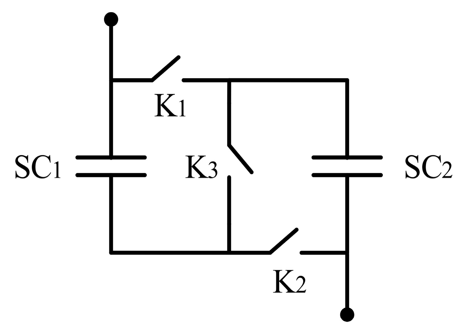
Figure 5.
Proposed series/parallel changeover circuit for storage bank.
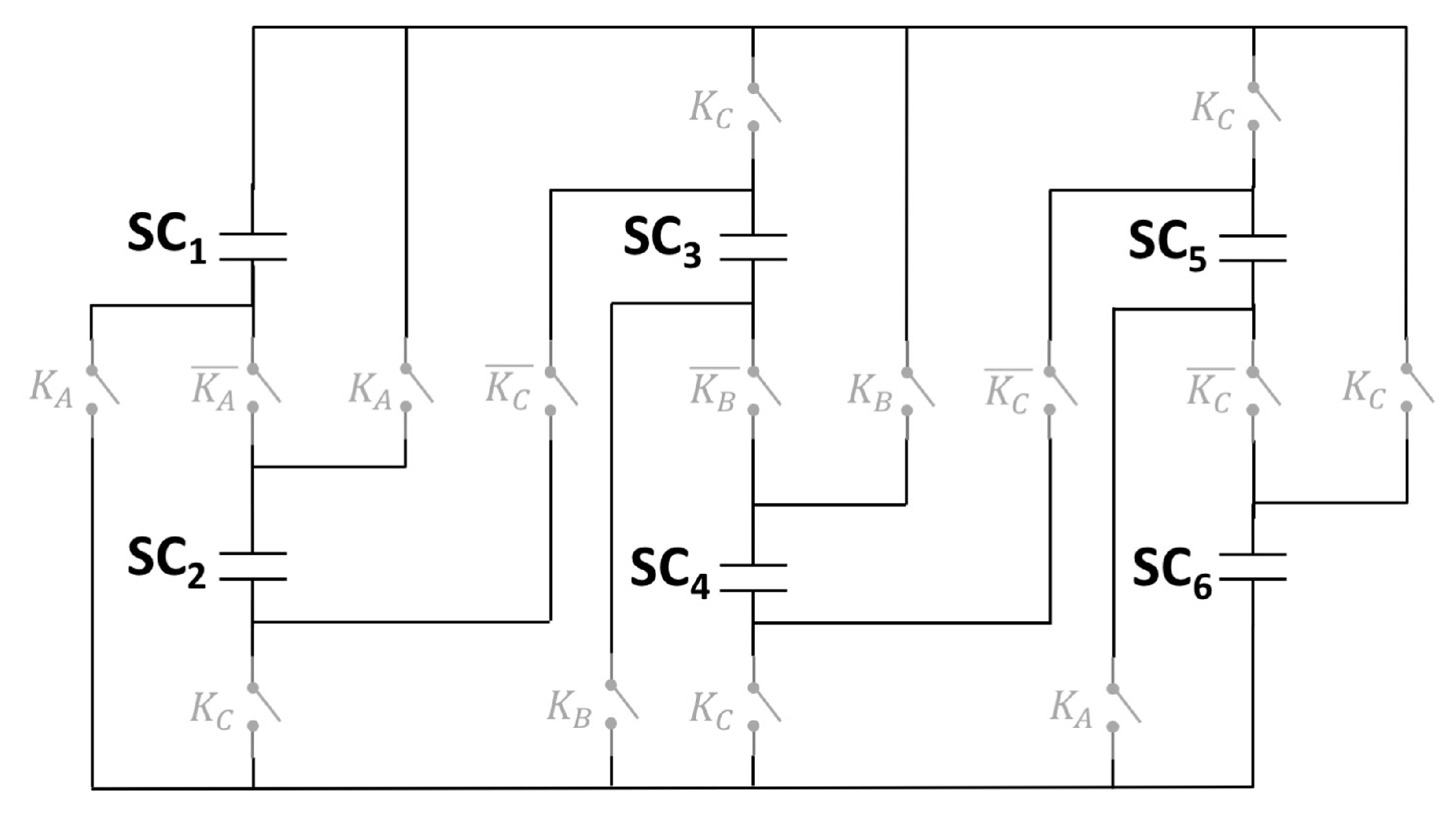
Figure 6.
Schematic diagram of the operation of the storage bank.
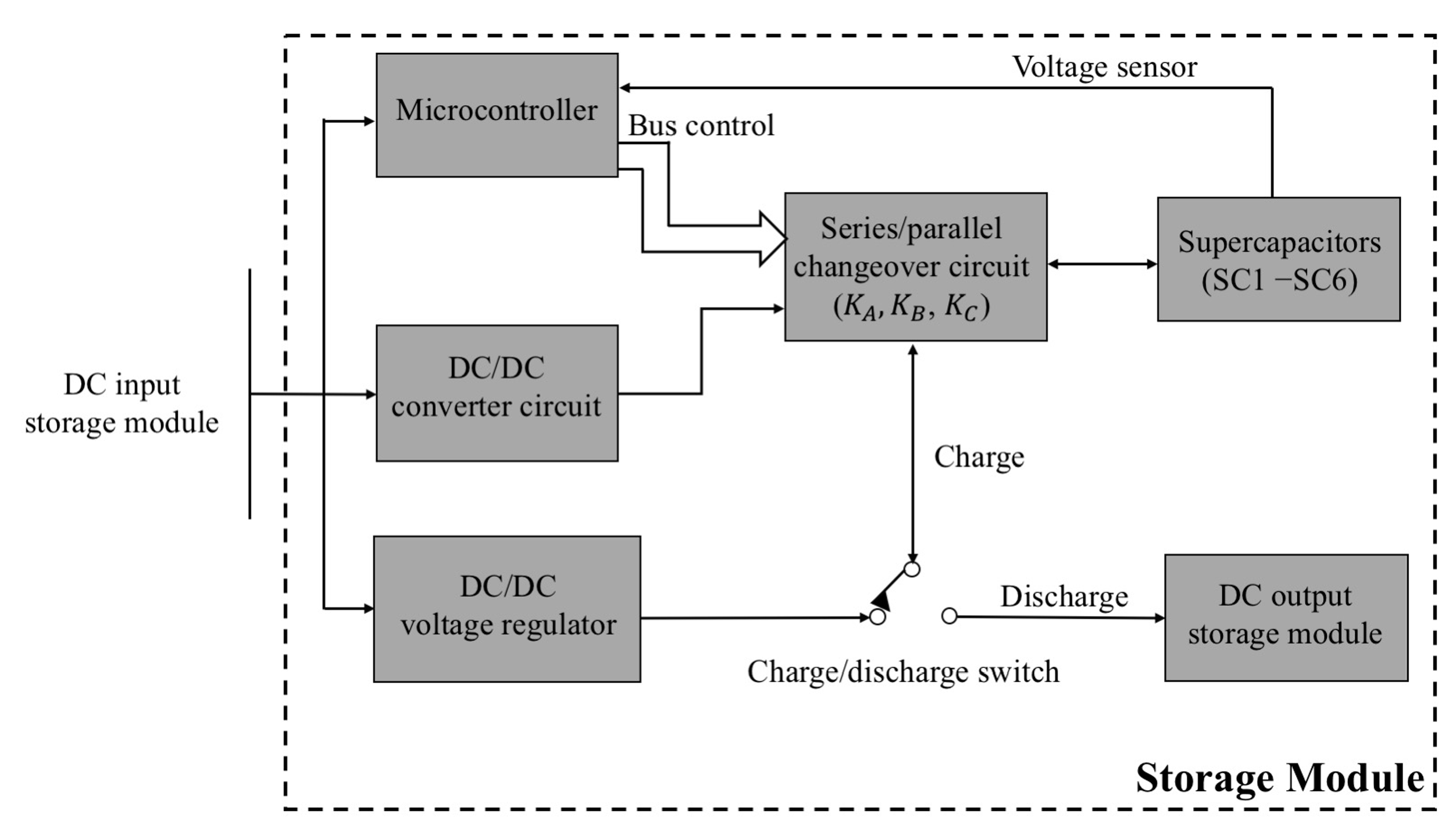
Figure 7.
Electrical circuits of the storage bank.
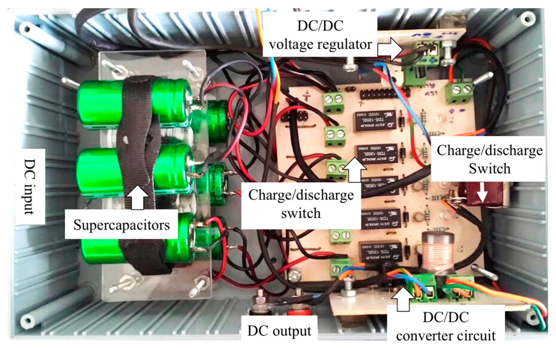
Figure 8.
Test bank.
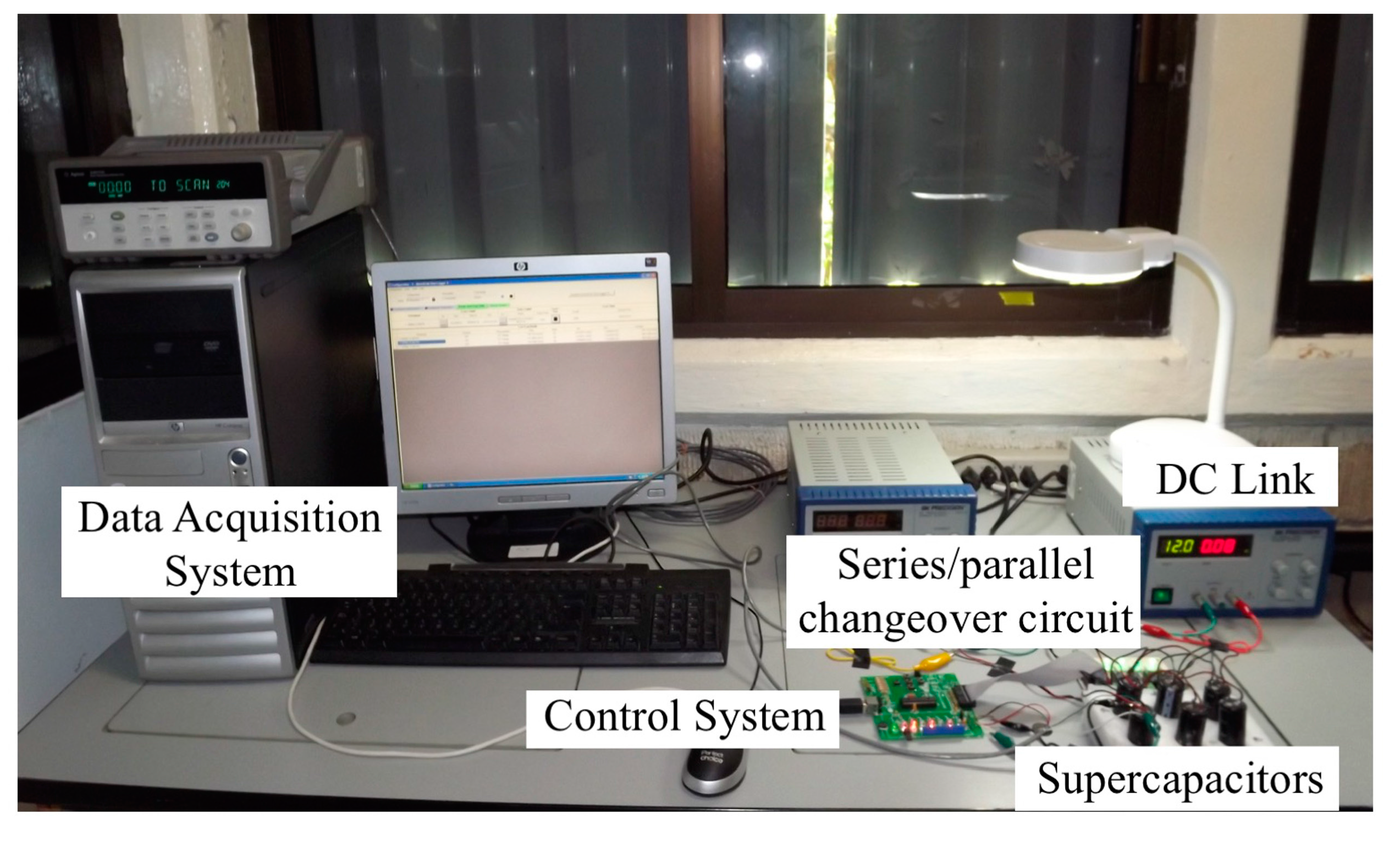
Figure 9.
Programmed discharge profiles recorded by the bank voltage. (a) ; (b) ; (c) ; and (d) .

Figure 10.
Average values calculated for energy extraction.


Table 1.
Programmed states of the SCB.
| Levels/Programmed States | Supercapacitor Electric Circuit | |
|---|---|---|
| (a) | VR1 111111 |  |
| (b) | VR2 010101 | 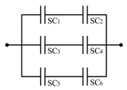 |
| (c) | VR3 001001 |  |
| (d) | VR4 000000 | 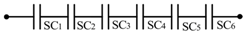 |
Table 2.
Proposed routines and voltage values in each SC of the bank.
| Level | Limit Variable | Limit 0.6 V | Limit 0.7 V | Limit 0.8 V |
|---|---|---|---|---|
| 0.50 | 0.60 | 0.70 | 0.80 | |
| 0.33 | 0.30 | 0.35 | 0.40 | |
| 0.16 | 0.20 | 0.23 | 0.26 | |
| 0.10 | 0.10 | 0.11 | 0.13 |
Table 3.
Reading and calculated time increment in all configuration routines.
| Routines | Time Increment (s) | Time Increment (%) |
|---|---|---|
| Limit variable () | 253 | 22.06 |
| Limit 0.6 V () | 287 | 30.93 |
| Limit 0.7 V () | 281 | 38.13 |
| Limit 0.8 V () | 272 | 49.10 |
Table 4.
Calculated efficiency of the bank changeover circuit in all configuration routines.
| Routines | (Wh) | (Wh) | (Wh) | (%) |
|---|---|---|---|---|
| Limit variable () | 0.0903 | 0.0010 | 0.0891 | 99.75 |
| Limit 0.6 V () | 0.0883 | 0.0014 | 0.0866 | 99.65 |
| Limit 0.7 V () | 0.0930 | 0.0019 | 0.0907 | 99.56 |
| Limit 0.8 V () | 0.0910 | 0.0026 | 0.0877 | 99.20 |
© 2017 by the authors. Licensee MDPI, Basel, Switzerland. This article is an open access article distributed under the terms and conditions of the Creative Commons Attribution (CC BY) license (http://creativecommons.org/licenses/by/4.0/).
Share and Cite
MDPI and ACS Style
Reveles-Miranda, M.G.; Flota-Bañuelos, M.I.; Chan-Puc, F.; Pacheco-Catalán, D. Experimental Evaluation of a Switching Matrix Applied in a Bank of Supercapacitors. Energies 2017, 10, 2077. https://doi.org/10.3390/en10122077
AMA Style
Reveles-Miranda MG, Flota-Bañuelos MI, Chan-Puc F, Pacheco-Catalán D. Experimental Evaluation of a Switching Matrix Applied in a Bank of Supercapacitors. Energies. 2017; 10(12):2077. https://doi.org/10.3390/en10122077
Chicago/Turabian StyleReveles-Miranda, Maria Guadalupe, Manuel Israel Flota-Bañuelos, Freddy Chan-Puc, and Daniella Pacheco-Catalán. 2017. "Experimental Evaluation of a Switching Matrix Applied in a Bank of Supercapacitors" Energies 10, no. 12: 2077. https://doi.org/10.3390/en10122077
Note that from the first issue of 2016, this journal uses article numbers instead of page numbers. See further details here.