Experimental Study on the Mechanical Properties of CH4 and CO2 Hydrate Remodeling Cores in Qilian Mountain


Key Laboratory of Ocean Energy Utilization and Energy Conservation of the Ministry of Education, Dalian University of Technology, Dalian 116024, China
*
Author to whom correspondence should be addressed.
Energies 2017, 10(12), 2078; https://doi.org/10.3390/en10122078
Submission received: 12 October 2017
/
Revised: 3 December 2017
/
Accepted: 4 December 2017
/
Published: 7 December 2017
Abstract
:The CH4-CO2 replacement method has attracted global attention as a new promising method for methane hydrate exploitation. In the replacement process, the mechanical stabilities of CH4 and CO2 hydrate-bearing sediments have become problems requiring attention. In this paper, considering the hydrate characteristics and burial conditions of hydrate-bearing cores, sediments matrices were formed by a mixture of kaolin clay and quartz sand, and an experimental study was focused on the failure strength of CH4 and CO2 hydrate-bearing sediments under different conditions to verify the mechanical reliability of CH4-CO2 replacement in permafrost-associated natural gas deposits. A series of triaxial shear tests were conducted on the CH4 and CO2 hydrate-bearing sediments under temperatures of −20, −10, and −5 °C, confining pressures of 2.5, 3.75, 5, 7.5, and 10 MPa, and a strain rate of 1.0 mm/min. The results indicated that the failure strength of the CO2 hydrate-bearing sediments was higher than that of the CH4 hydrate-bearing sediments under different confining pressures and temperatures; the failure strength of the CH4 and CO2 hydrate-bearing sediments increased with an increase in confining pressure at a low confining pressure state. Besides that, the failure strength of all hydrate-bearing sediments decreased with an increase in temperature; all the failure strengths of the CO2 hydrate-bearing sediments were higher than those of the CH4 hydrate-bearing sediments in different sediment matrices. The experiments proved that the hydrate-bearing sediments would be more stable than that before CH4-CO2 replacement.
1. Introduction
Methane hydrate has attracted the attention of scientists worldwide [1,2,3,4,5,6,7,8,9,10,11,12]. In 2008, methane hydrate cores were obtained by drilling in hydrate reservoirs located in Qilian Mountain, China [13,14]. The mining of natural gas in methane hydrate reservoirs may effectively alleviate the energy risk caused by the decrease of petroleum.
The CH4-CO2 replacement method has been one of the important methods for mining the natural gas in hydrate reservoirs; the core principle of CH4-CO2 replacement is that the phase equilibrium pressure of CH4 hydrate is higher than that of CO2 hydrate at the same temperature when the temperature is below 283 K [15,16,17,18]. The CO2 hydrate can form in some pressure–temperature conditions which are outside the methane hydrate’s phase stability field. Therefore, the CH4 hydrate will decompose whereas the CO2 hydrate can remain stable when the gas hydrate storage deposit’s pressure drops down below the phase equilibrium pressure of CH4 hydrate; then, CO2 will be injected into the methane gas hydrate storage deposits to generate CO2 hydrate and release methane gas. All the processes above are called the CH4-CO2 replacement method.
The thermodynamic feasibility of CH4-CO2 replacement has been proved. Ota et al. [17,18] confirmed that CH4-CO2 replacement mainly occurs in the hydrate phase at fixed temperatures in experiments. Ohgaki et al. [19] measured a CH4-CO2 mixed hydrate system at 280 K and obtained the isothermal phase equilibrium relationships between the components and pressure in multiple phases, proving the feasibility of CH4-CO2 replacement for the first time. Hirohama et al. [20] described the driving force of CH4-CO2 replacement through measuring the CH4 formation rate when CH4 gas hydrate was dipped in CO2 liquid. Besides that, a mathematical model based on non-steady state thermodynamics was proposed. Yoon et al. [21] observed that CO2 hydrate, CH4 hydrate, and liquid water would coexist in the guest molecules when high-pressure CO2 was injected into CH4 hydrate.
Besides this, the physical properties of hydrate-bearing sediments in CH4-CO2 replacement also have been studied. Jung et al. [15,16] studied the physical properties of hydrate-bearing sediments in the CH4-CO2 replacement process, and combined the results with previous studies to analyze the underlying phenomenon. Wang et al. [22] proved that the P-wave velocity and amplitude of the hydrate-bearing sediments behave in the same way and decrease slightly because of the dissociation of CH4 hydrate when free CH4 gas is released and CO2 gas is injected. Liu et al. [23] also found that the P-wave velocity continually decreased during all replacement processes. Hyodo et al. [24] confirmed that newly formed CO2 hydrate would keep the reservoir mechanically stable when CH4-CO2 replacement took place in a relatively short period of time in sediments formed by Toyoura sand.
Gas hydrate cores were recovered in the Qilian Mountain permafrost located in the Qinghai-Tibet Plateau, China. This region is expected to become a strategic gas hydrate exploitation area in China [13,14]. Thus, to assess the feasibility of the CH4-CO2 replacement recovery method and the long-term stability of the hydrate reservoir in Qilian Mountain, the mechanical properties of CH4 and CO2 hydrate-bearing sediments should be clearly investigated. So, in this paper, considering the real buried conditions, a component analysis, and the particle size distributions of cores in Qilian Mountain, a sediment matrix was obtained by mixing kaolin clay and quartz sand in a constant proportion [13,14]. Then, the mechanical properties of CH4 and CO2 hydrate-bearing sediments in different sediment matrices were studied for investigating the stability of methane hydrate deposits. In addition, the cohesion and friction angles are be calculated to analyze the failure strength of hydrate-bearing sediments.
2. Experimental Methods
2.1. Experimental Apparatus
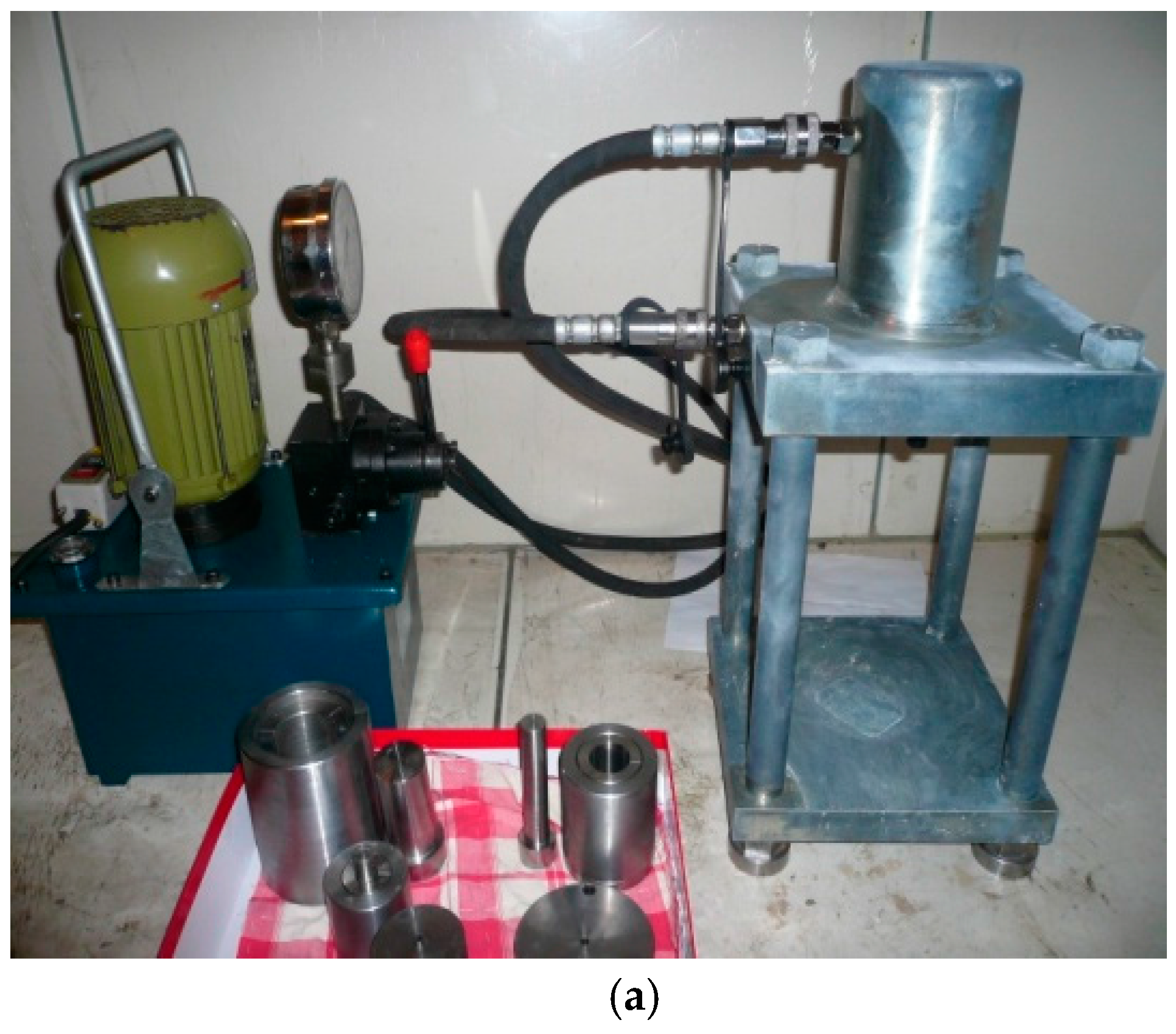
Figure 1 shows the schematic diagram of the triaxial apparatus, and Figure 2 shows the appearance of the triaxial apparatus used in this study. The maximum axial load was 200 kN provided by the load cell; the maximum confining pressure was 30 MPa provided by the plunger pump; the temperature could range from −20 °C to 25 °C with an accuracy of 0.1 °C controlled by the refrigerator and thermostatic bath. Figure 3 shows the pressure crystal device and the high pressure reaction vessel. The maximum axial pressure of the pressure crystal device was 10 MPa. The maximum volume and pressure of the high pressure reaction vessel was 200 mL and 20 MPa, respectively. Figure 4 shows the top and bottom platens, the rubber membrane, and the seals. The top and bottom platens were 50 mm in diameter and 30 mm in height, with a pathway in the center of two platens which were used to connect to an external valve. The rubber membrane was 50 mm in diameter, 140 mm in height, and 0.5 mm in thickness. The seals were 48 mm in diameter.
2.2. Sample Preparation
In the hydrate formation process, firstly an ice cube was made by using sodium dodecyl sulfate (SDS) reagent (the concentration of SDS is 10 mg/L) with a certain amount of water in a refrigerator (about −10 °C), and then it was crushed and sieved by a filter sieve of 60 mesh to make ice powder with a particle size of about 250 μm. Then, the ice powder was put into the chamber of a high-pressure reaction vessel, which is shown in Figure 3b. The temperature of the chamber was raised to 0 °C for about 1 h until part of the ice had melted to water. Then, the cap and the chamber of the high-pressure reaction vessel were joined together, and CH4 of 10 MPa or CO2 of 5 MPa gas, which was precooled to 0 °C, was injected into the high-pressure reaction vessel. After that, the high-pressure reaction vessel was closed and put into a cold storage room (about −10 °C) to form hydrate in 48 h. According to the mass defect of hydrate containing ice before and after hydrate dissociation, all of the hydrate fractions were about 30% and the equation for calculating the hydrate fraction was as below;
where Sh is the hydrate fraction, Vh is the volume of the hydrate, Vice is the volume of the ice, mmix.bef is the mass of the ice and hydrate mixtures before dissociation, mmix.aft is the mass of the ice and hydrate mixtures after dissociation, Mh is the molar mass of the hydrate (119.5 g/mol for CH4 hydrate and 147.5 g/mol for CO2 hydrate), and Mgas is the molar mass of the gas.
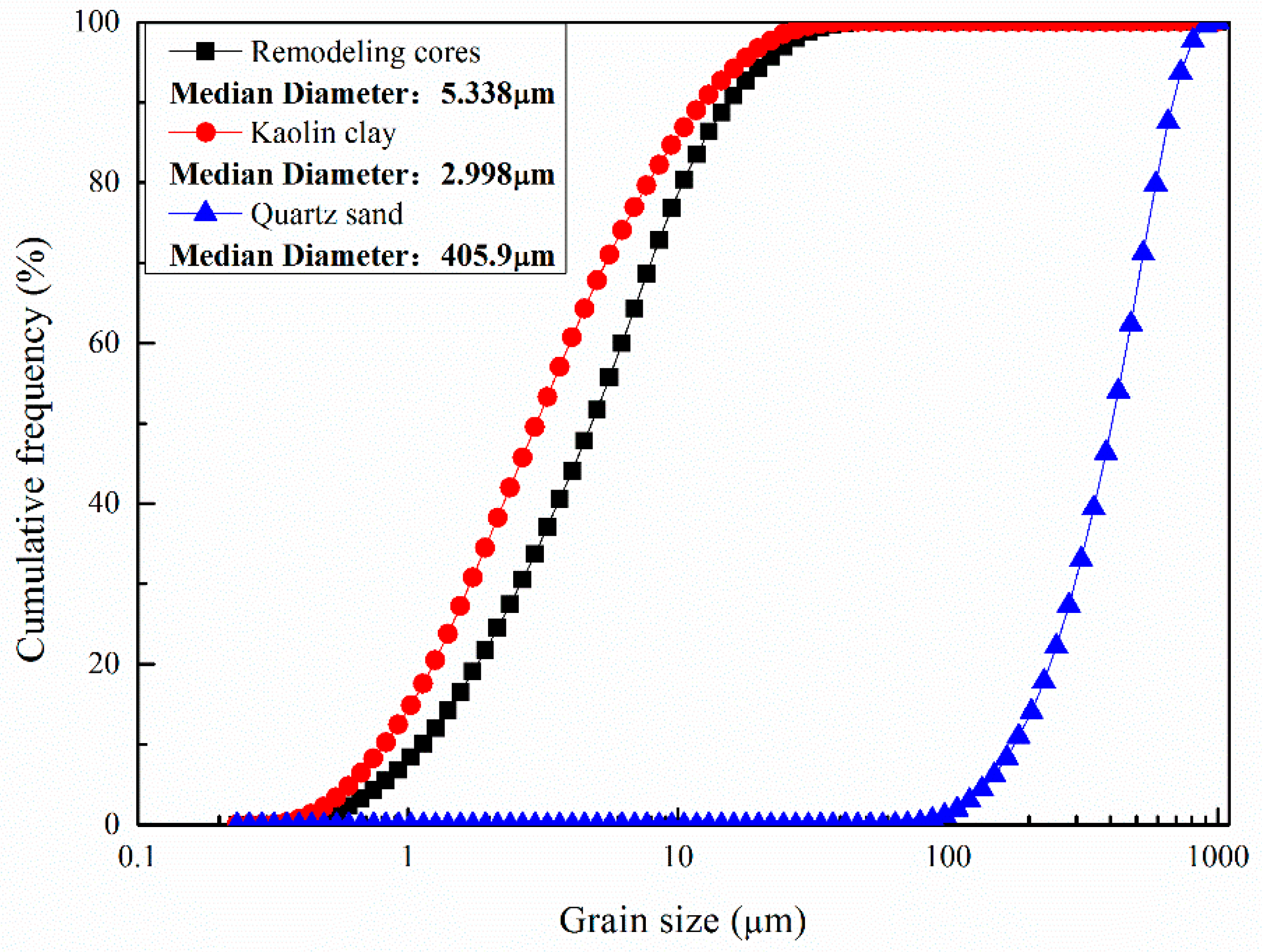
According to the component analysis and particle size distributions of cores in Qilian Mountain (approximately 70% volume kaolin clay and 30% volume quartz sand, where the median diameter of the cores ranges between 3.72 μm and 7.63 μm and approximately focuses on about 5–6 μm), the sediment matrix was prepared by a certain proportion of sieved kaolin clay and quartz sand [13,14]. Figure 5 shows the particle size distributions of the remodeling cores, the kaolin clay, and the quartz sand. In this study, all of the particle size distribution curves of the sediment matrices were obtained with a laser particle size analyser (BT-9300ST, Dandong Bettersize Instruments Co. Ltd., Dandong, China).
In this study, the porosity (40%) was controlled and calculated by the volume ratio of hydrate–ice mixtures to the sample, and the pore spaces of sediments were almost fully filled by the hydrate–ice mixtures. The volume ratios of sediment matrix, ice, and hydrate to the sample were about 60%, 28%, and 12%, respectively. The sediment matrix and hydrate containing ice were weighed and mixed evenly, then the mixture was put into a pressure crystal device in 10 equal layers (5 MPa pressure) to form a sample that was 50 mm in diameter and 100 mm in height. Figure 6 shows the samples of CH4 hydrate-bearing sediments. Besides that, the whole process occurred in a cold storage room (about −10 °C).
2.3. Experimental Procedures
All triaxial shear tests were conducted mainly based on the Geotechnical tests criteria and were carried out in a cold storage room (about −10 °C) to reduce hydrate dissociation. Two end platens were firstly put on the top and bottom sides of sample, then a rubber membrane was wrapped around the sample, and seals were used to tighten the rubber membrane and end platens. After that, the sample was vertically placed into the pressure chamber. Besides that, the confining pressure and temperature were respectively provided by the internal and external confining pressure loading system and the temperature control system. After consolidation for 1.5 h, the sample was sheared.
The mechanical properties of the hydrate-bearing sediments were extremely sensitive to temperature, confining pressure, strain rate, and porosity [24]. Considering the actual burial conditions of the hydrate-bearing sediments in reservoirs located in Qilian Mountain, the hydrate existed in layers in which the drilling depth ranged from 0 m to 400 m, the temperature ranged from about −10 °C to −1.8 °C, and the hydrate fractions in the drilling core mostly focused on 25–36%. To study the mechanism of the effect of confining pressure and temperature on the mechanical properties of hydrate-bearing sediments, the experiments for CO2 and CH4 hydrate-bearing sediments were carried out with a porosity of 40%, a hydrate fraction of 30%, temperatures of −20, −10, and −5 °C, confining pressures of 2.5, 3.75, 5, 7, and 10 MPa, and a strain rate of 1.0 mm/min [13,14].
The phase equilibrium curves of the CO2 hydrate and the CH4 hydrate are shown in Figure 7 [25]. It can be found that CO2 hydrate and CH4 hydrate will be stable in the pressure and temperature conditions in this study. Besides that, all triaxial tests were replicated twice to ensure the reliability of the compression test.
3. Results and Discussions
3.1. The Effect of Confining Pressure
In this paper, according to the Geotechnical test criteria (China), the deviator stress in 15% axial strain was taken as the failure strength of a sample when the obvious peak strength does not exist.
Figure 8 shows the stress-strain curves of the CH4 and CO2 hydrate-bearing sediments under different confining pressures, a temperature of −10 °C, and a strain rate of 1.0 mm/min. In Figure 8, it can be observed that the stress-strain curves of all of the hydrate-bearing sediments can be described as a hyperbola formula and present three stages. In the first elastic stage, the deviator stress increases nearly linearly with the increase of axial strain until the axial strain gets to about 3%, and the hydrate-bearing sediments exhibit high stiffness. In the elastic-plastic stage, the deviator stress continues to increase but the increasing rate of the deviator stress gradually reduces to zero, which means that the sample starts to yield, and the elastic-plastic stage almost occupies all of the stress-strain curves. In the last yield stage, the deviator stress achieves its maximum and stays at a constant level. Additionally, a significantly continuous hardening tendency up to the end of testing for all of the hydrate-bearing sediments was shown out when the axial strain was more than 16%. Previous work has reported similar stress-strain behaviors for frozen soil and hydrate-bearing sediments [8,26,27,28]. In addition, the effects of confining pressure on the stress-strain relationship of CH4 hydrate-bearing sediments were consistent with that of CO2 hydrate-bearing sediments.
Figure 9 displays the failure strength of the CH4 and CO2 hydrate-bearing sediments under different confining pressures at a strain rate of 1.0 mm /min and a temperature of −10 °C. The results show clearly that the failure strength of the CO2 hydrate-bearing sediments is higher than that of the CH4 hydrate sediments under different confining pressures, and CH4-CO2 replacement is beneficial to the stability of the reservoir [23,24]. Besides this, in the shear process, the strength of the hydrate-bearing sediments may consist of the strength of ice, hydrate, and sediment matrix and their interaction [29]. According to the literature, CO2 hydrate has a larger unit cell volume than CH4 due to the larger lattice parameter with the guest size of CO2 hydrate, which may cause higher strength CO2 hydrate particles and a higher interaction strength between CO2 hydrate particles and sediment matrix particles than those of CH4 hydrate [25,30]. In addition, it may be because of the hydrate dissociation caused by particle crushing during shear. More CH4 hydrate was dissociated than CO2 hydrate due to their dynamic stability differences, which decreased the strength of the sample [31].
It is also seen that the failure strength clearly depends on the confining pressure [32,33]. The failure strength of the CH4 and CO2 hydrate-bearing sediments increased linearly when the confining pressure was less 5 MPa and arrived at a maximum at about 7.5 MPa pressure. When the confining pressure was higher than 7.5 MPa, the failure strength started to decrease. These results are consistent with previous research [34,35]. According to Yun and Li [8,34], an increase in confining pressure can lead to the compaction of a sample, preventing the hydrate crystals from detaching from the mineral’s surface or rotating. Then, the bonding strength and friction between the particles are enhanced. So, a higher confining pressure will lead to the enhancement of the strength of the sediments when the confining pressure is less than 7.5 MPa. However, the strength shows a downward trend with a further increase in the confining pressure, which may be due to particle breakage caused by stress concentration in a higher confining pressure.
3.2. Effect of Temperature
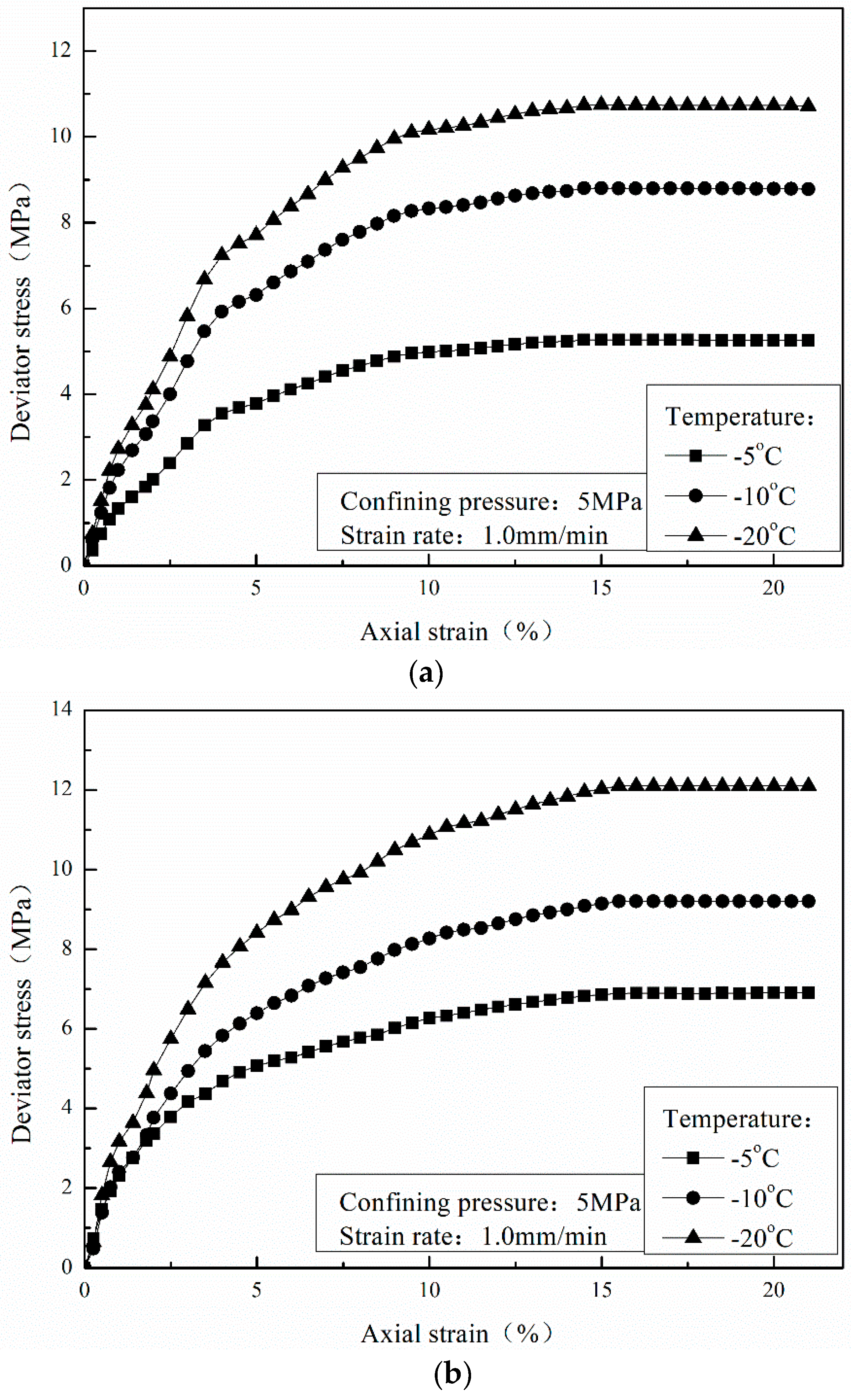
Figure 10 shows the stress-strain curves of the CH4 and CO2 hydrate-bearing sediments when the temperatures are −20, −10, and −5 °C, the confining pressure is 5 MPa, and the strain rate is 1.0 mm/min. The stress-strain curves of the CH4 hydrate-bearing sediments also present three stages, which are consistent with those of the CO2 hydrate-bearing sediments under different temperatures. The effects of temperature on the stress-strain relationships of the CH4 hydrate-bearing sediments are consistent with those of the CO2 hydrate-bearing sediments.
Figure 11 shows the failure strength of the CH4 and CO2 hydrate-bearing sediments under different temperatures of −20, −10, −5 °C, with a confining pressure of 5 MPa and a strain rate of 1.0 mm/min. In Figure 11, it can be found that the failure strength of a sediment is dependent on the temperature. The lower the temperature, the higher the failure strength of a hydrate-bearing sediment. These results confirm the conclusions of previous chemical research on hydrates [29]. Yu et al. [36] had noted that the static shear strength of methane hydrate-bearing sediments was affected by temperature. Moreover, previous experimental results have shown that pore-ice pressure melting occurs locally at grain-to-grain contacts under high stresses in frozen soils [37,38,39]. In the shear process, the hydrate and ice content in the sample may range with the change of temperature and pressure; specifically, the ice content may significantly change due to the pressure melting phenomenon. The water content increases with the temperature and confining pressure, which may decrease the failure strength of hydrate-bearing sediments.
Moreover, the failure strengths of the CO2 hydrate-bearing sediments were all higher than those of the CH4 hydrate-bearing sediments, which may prove the mechanical feasibility of CH4-CO2 replacement.
3.3. Effect of Sediment Matrix
To study the influence of the particle size distributions of a sediment matrix on the mechanical properties of CH4 and CO2 hydrate-bearing sediments, kaolin clay and crushed quartz sand were separately used as the sediment matrix of the hydrate-bearing sediments.
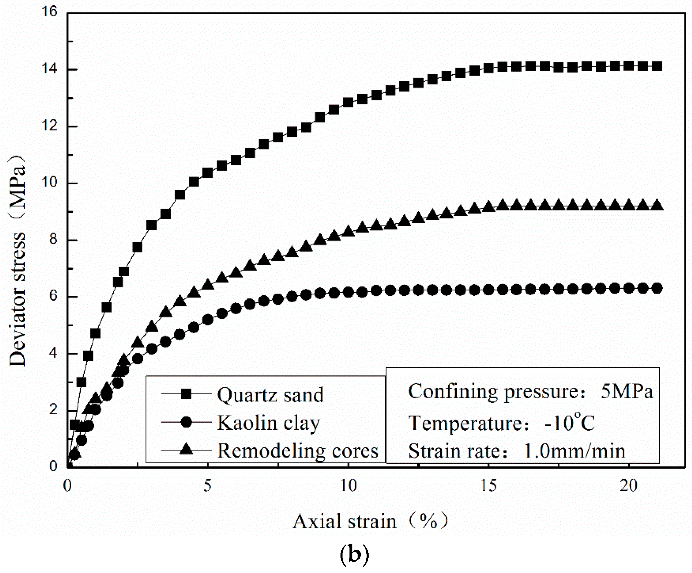
Figure 12 shows the stress-strain curves of the CH4 and CO2 hydrate-bearing sediments in different sediment matrices under a confining pressure of 5 MPa, a temperature of −10 °C, and a strain rate of 1.0 mm/min. In Figure 12, all of the stress-strain curves of the CH4 and CO2 hydrate-bearing sediments experience three stages. However, the elastic-plastic stage of samples formed by quartz sand and remodeling cores occurs lately and is longer than that of samples formed by kaolin clay.
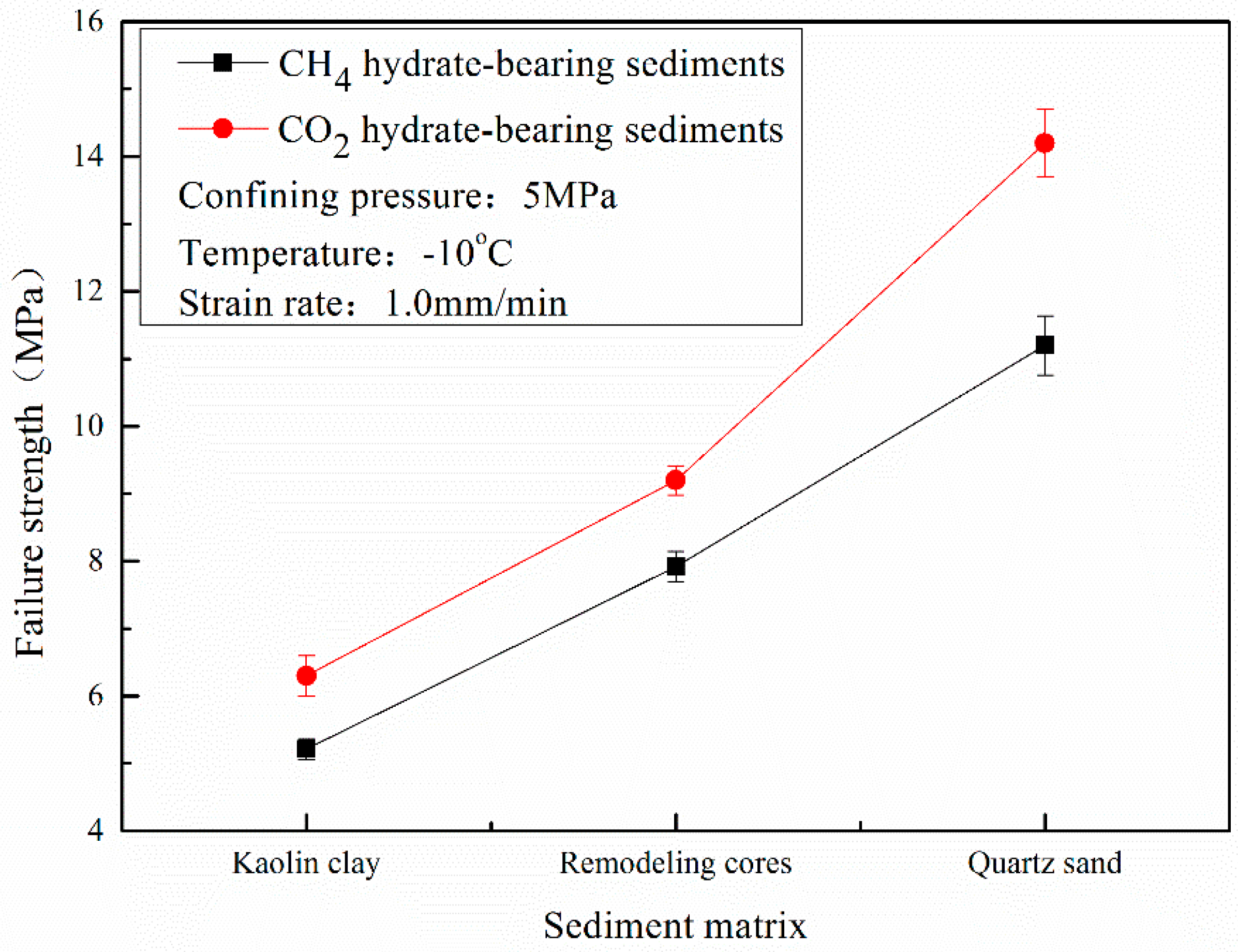
Figure 13 shows the failure strength of the CH4 and CO2 hydrate-bearing sediments in different host sediment matrices under a confining pressure of 5 MPa, a temperature of −10 °C, and a strain rate of 1.0 mm/min. It can be noted that all of the failure strengths of the CO2 hydrate-bearing sediments are higher than those of the CH4 hydrate-bearing sediments in different sediment matrices. The influencing effects of the sediment matrices formed by kaolin clay, remodeling cores, or quartz sand on the CH4 and CO2 hydrate-bearing sediments are consistent, which confirms the mechanical feasibility and the stability of layers in the CH4-CO2 replacement method.
Moreover, the failure strength of samples formed by crushed quartz sand was higher than that of samples formed by remodeling cores, and the failure strength of samples formed by remodeling cores was higher than that of samples formed by kaolin clay. The strength of the sediment matrix plays an important role in the failure strength of hydrate-bearing sediments when the degree of hydrate saturation is below 40% [8]. In hydrate-bearing sediments, the frictional force between the particles increases with an increase in the average particle size of the sediment matrix, which will enhance the failure strength of hydrate-bearing sediments [40,41]. Besides this, the failure strength of the CO2 hydrate-bearing sediments was greater than that of the CH4 hydrate-bearing sediments in the three sediment matrices.
3.4. Mohr–Coulomb Strength Theory
The Mohr–Coulomb (M-C) strength criterion is the most widely used theory for analyzing the mechanical properties of hydrate-bearing sediments. In the Mohr–Coulomb strength criterion, by calculating the intercept and the slope of the strength envelopes, the cohesive force and the internal friction angle can be acquired in order to study the internal mechanism of failure strength. Cohesive force reflects the synthesis action of physical–chemical forces between particles, and the internal friction angle represents the friction characteristic of a material. For cohesive soil, the mathematical expression of the M-C criterion is:
where τ is the shear strength, c is the cohesion force, σ is the normal stress, and ϕ is the internal friction angle.
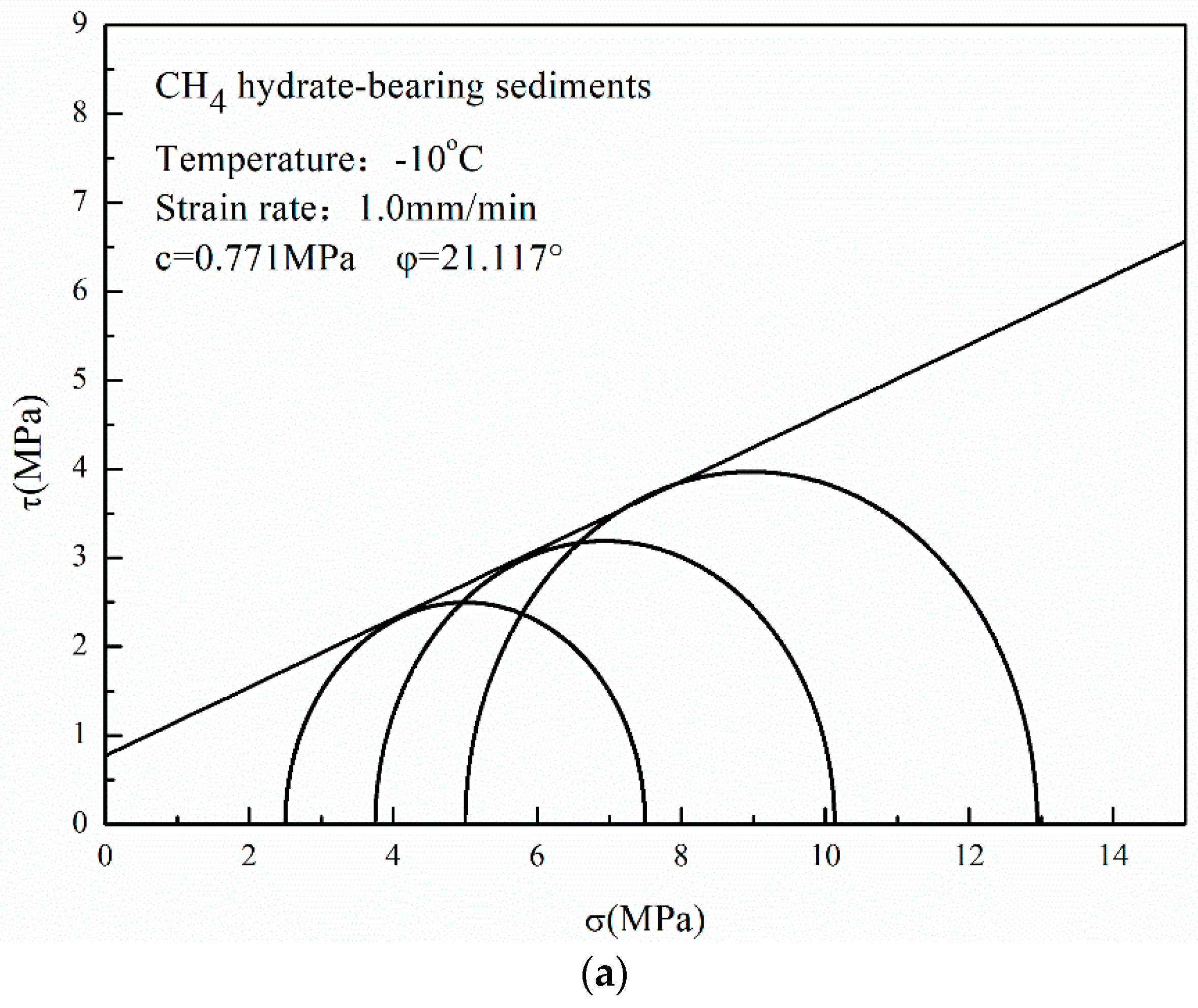
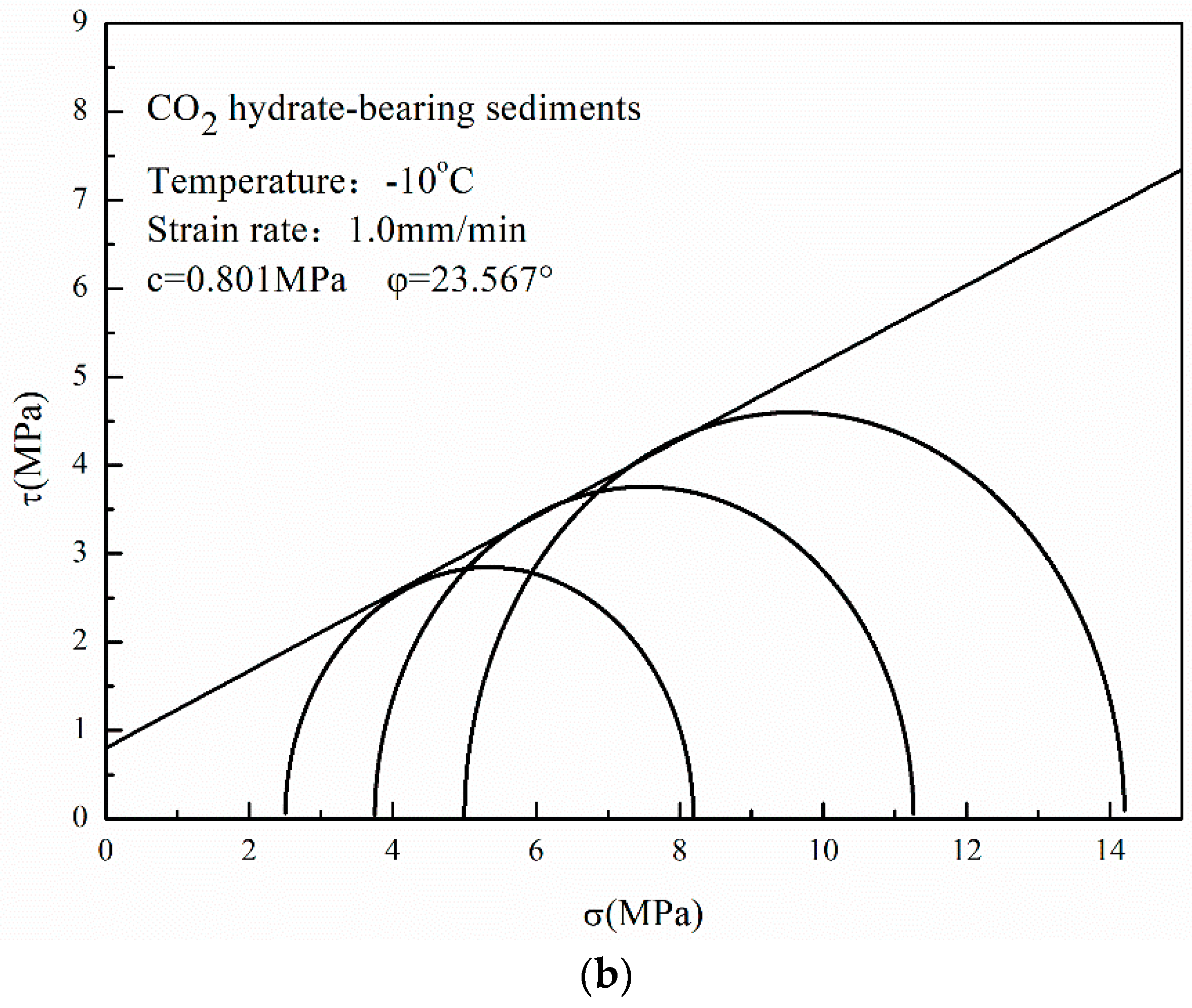
Figure 14 shows the Mohr stress circles and the envelopes of the CH4 and CO2 hydrate-bearing sediments under the low confining pressures of 2.5, 3.75, and 5 MPa. In Figure 14, three Mohr’s stress circles are presented with the deviator stress and confining pressure of the hydrate-bearing sediments under the low confining pressures of 2.5, 3.75, and 5 MPa. In the Mohr’s stress circles, the value of the deviator stress is equal to the value of the diameter of the Mohr’s stress circles, and the value of the circle dot is equal to the value of the confining pressure plus the value of the radius. When the Mohr’s stress circle is tangent to the shear strength envelope, the shear stress at the point of tangency is defined as the cohesive force, and the angle between the shear strength envelopes and the horizontal axis is defined as the internal friction angle. As shown in Figure 14, the cohesive force and the internal friction angle of the CO2 hydrate-bearing sediments are both higher than those of the CH4 hydrate-bearing sediments. The increase in internal friction angle is more significant than that of cohesive force; thus, the internal friction angle plays an important role in the failure strength of hydrate-bearing sediments in the CH4-CO2 replacement method.
When the CH4-CO2 replacement in the hydrate reservoirs of Qilian Mountain was finished, the internal friction angle and the cohesive force between the CO2 hydrate particles and the sediment matrix particles in the newly generated CO2 hydrate-bearing sediments were larger than those between the CH4 particles and the sediment matrix particles in the CH4 hydrate-bearing sediments, so the stability of the reservoir was proved. Moreover, the mechanical properties of the hydrate-bearing sediments varied with hydrate saturation, particle size distribution, confining pressure, and temperature. It is difficult to find a model or an equation which is suitable for all conditions. In this study, we hope the results can be used to assess the stability of the hydrate-bearing layer in Qilian Mountain.
4. Conclusions
In this study, we applied a low-temperature, high-pressure triaxial apparatus to study mechanical properties of CH4 and CO2 hydrate-bearing remodeling cores. The conclusions are below:
- (1)
- The stress-strain curves of CO2 hydrate-bearing sediments are consistent with that of CH4 hydrate-bearing sediments. The effects of temperature, confining pressure, and sediment matrices on the stress-strain relationships of CH4 hydrate-bearing sediments are consistent with the effects of those on CO2 hydrate-bearing sediments.
- (2)
- The failure strength of CO2 hydrate-bearing sediments is higher than that of CH4 hydrate sediments under different confining pressures, temperatures, and sediment matrices. The failure strength of the CH4 and CO2 hydrate-bearing sediments first increased and then decreased with an increase in confining pressure, and achieved a maximum at 7.5 MPa.
- (3)
- The cohesion and the internal friction angle of CO2 hydrate-bearing sediments are both higher than those of CH4 hydrate-bearing sediments. The internal friction angle plays a dominant role in the failure strength of CH4 and CO2 hydrate-bearing sediments. In this study, all of the experiments and the theoretical analysis proved the stability of the reservoir in Qilian Mountain under CH4-CO2 replacement.
Acknowledgments
This study was supported by the National Natural Science Foundation of China (Grant No. 51436003), the National Key Research and Development Program of China (Grant Nos. 2017YFC0307305 and 2016YFC0304001), and the National Natural Science Foundation of China (Grant Nos. 51676024 and 51509032).
Author Contributions
Tingting Luo, Yanghui Li and Weiguo Liu conceived and designed the experiments, Tingting Luo and Shi Shen performed the experiments, Tingting Luo and Weiguo Liu analyzed the data, Tingting Luo, Yanghui Li and Xiang Sun wrote the paper.
Conflicts of Interest
The authors declare no conflict of interest.
References
- Daigle, H.; Cook, A.; Malinverno, A. Permeability and porosity of hydrate-bearing sediments in the northern gulf of Mexico. Mar. Pet. Geol. 2015, 68, 551–564. [Google Scholar] [CrossRef]
- Kim, Y.G.; Lee, S.M.; Jin, Y.K.; Baranov, B.; Obzhirov, A.; Salomatin, A.; Shoji, H. The stability of gas hydrate field in the northeastern continental slope of Sakhalin island, sea of Okhotsk, as inferred from analysis of heat flow data and its implications for slope failures. Mar. Pet. Geol. 2013, 45, 198–207. [Google Scholar] [CrossRef]
- Kayen, R.E.; Lee, H.J. Pleistocene slope instability of gas hydrate-laden sediment on the beaufort sea margin. Mar. Georesour. Geotechnol. 1991, 10, 125–141. [Google Scholar] [CrossRef]
- Miyazaki, K.; Masui, A.; Aoki, K.; Sakamoto, Y.; Yamaguchi, T.; Okubo, S. Strain-rate dependence of triaxial compressive strength of artificial methane-hydrate-bearing sediment. Int. J. Offshore Polar Eng. 2010, 20, 256–264. [Google Scholar]
- Priest, J.A.; Clayton, C.R.I.; Rees, E.V.L. Potential impact of gas hydrate and its dissociation on the strength of host sediment in the Krishna-Godavari Basin. Mar. Pet. Geol. 2014, 58, 187–198. [Google Scholar] [CrossRef]
- Priest, J.A.; Druce, M.; Roberts, J.; Schultheiss, P.; Nakatsuka, Y.; Suzuki, K. Pcats triaxial: A new geotechnical apparatus for characterizing pressure cores from the Nankai Trough, Japan. Mar. Pet. Geol. 2015, 66, 460–470. [Google Scholar] [CrossRef]
- Yoneda, J.; Hyodo, M.; Yoshimoto, N.; Nakata, Y.; Kato, A. Development of high-pressure low-temperature plane strain testing apparatus for methane hydrate-bearing sand. Soils Found. 2013, 53, 774–783. [Google Scholar] [CrossRef]
- Yun, T.S.; Santamarina, J.C.; Ruppel, C. Mechanical properties of sand, silt, and clay containing tetrahydrofuran hydrate. J. Geophys. Res. Solid Earth 2007, 112. [Google Scholar] [CrossRef]
- Zhao, J.; Liu, D.; Yang, M.; Song, Y. Analysis of heat transfer effects on gas production from methane hydrate by depressurization. Int. J. Heat Mass Transf. 2014, 77, 529–541. [Google Scholar] [CrossRef]
- Zhao, J.; Yao, L.; Song, Y.; Xue, K.; Cheng, C.; Liu, Y.; Zhang, Y. In situ observations by magnetic resonance imaging for formation and dissociation of tetrahydrofuran hydrate in porous media. Magn. Reson. Imaging 2011, 29, 281–288. [Google Scholar] [CrossRef] [PubMed]
- Zhao, J.; Yu, T.; Song, Y.; Liu, D.; Liu, W.; Liu, Y.; Yang, M.; Ruan, X.; Li, Y. Numerical simulation of gas production from hydrate deposits using a single vertical well by depressurization in the QiLian Mountain permafrost, QingHai-Tibet Plateau, China. Energy 2013, 52, 308–319. [Google Scholar] [CrossRef]
- Zhao, J.; Zhu, Z.; Song, Y.; Liu, W.; Zhang, Y.; Wang, D. Analyzing the process of gas production for natural gas hydrate using depressurization. Appl. Energy 2015, 142, 125–134. [Google Scholar] [CrossRef]
- Lu, Z.; Zhu, Y.; Zhang, Y.; Wen, H.; Li, Y. Basic geological characteristics of gas hydrates in QiLian Mountain permafrost area, QingHai Province. Miner. Depos. China 2010, 29, 182–193. [Google Scholar]
- Pang, S.; Su, X.; He, H.; Zhao, Q. Geological controlling factors of gas hydrate occurrence in QiLian Mountain permafrost. Earth Sci. Front. China 2013, 20, 223–229. [Google Scholar]
- Jung, J.W.; Espinoza, D.N.; Santamarina, J.C. Properties and phenomena relevant to CH4-CO2 replacement in hydrate-bearing sediments. J. Geophys. Res. 2010, 115. [Google Scholar] [CrossRef]
- Jung, J.W.; Santamarina, J.C. CH4-CO2 replacement in hydrate-bearing sediments: A pore-scale study. Geochem. Geophys. Geosyst. 2010, 11. [Google Scholar] [CrossRef]
- Ota, M.; Abe, Y.; Watanabe, M.; Smith, R.L.; Inomata, H. Methane recovery from methane hydrate using pressurized CO2. Fluid Phase Equilib. 2005, 228–229, 553–559. [Google Scholar] [CrossRef]
- Ota, M.; Saito, T.; Aida, T.; Watanabe, M.; Sato, Y.; Smith, R.L.; Inomata, H. Macro and microscopic CH4-CO2 replacement in CH4 hydrate under pressurized CO2. AIChE J. 2007, 53, 2715–2721. [Google Scholar] [CrossRef]
- Ohgaki, K.T.; Sangawa, H.; Matsubara, T.; Nakano, S. Methane exploitation by carbon dioxide from gas hydrates-phase equilibria for CH4-CO2 mixed hydrate system. J. Chem. Eng. Jpn. 1996, 29, 478–483. [Google Scholar] [CrossRef]
- Hirohama, Y.S.; Wakabayashi, A.; Tatsuta, S.; Nishida, N. Conversion of CH4-hydrate to CO2-hydrate in liquid CO2. J. Chem. Eng. Jpn. 1996, 29, 1014–1020. [Google Scholar] [CrossRef]
- Yoon, J.H.; Kawamura, T.; Yamamoto, Y.; Komai, T. Transformation of methane hydrate to CO2 hydrate: In situ raman spectroscopic observations. Phys. Chem. A 2004, 108, 5057–5059. [Google Scholar] [CrossRef]
- Wang, X.H.; Li, F.G.; Xu, Y.X.; Sun, C.Y.; Pan, H.; Liu, B.; Yang, L.Y.; Chen, G.J.; Li, Q.P. Elastic properties of hydrate-bearing sandy sediment during CH4-CO2 replacement. Energy Convers. Manag. 2015, 99, 274–281. [Google Scholar] [CrossRef]
- Liu, B.; Pan, H.; Wang, X.; Li, F.; Sun, C.; Chen, G. Evaluation of different CH4-CO2 replacement processes in hydrate-bearing sediments by measuring P-wave velocity. Energies 2013, 6, 6242–6254. [Google Scholar] [CrossRef]
- Hyodo, M.; Li, Y.; Yoneda, J.; Nakata, Y.; Yoshimoto, N.; Kajiyama, S.; Nishimura, A.; Song, Y. A comparative analysis of the mechanical behavior of carbon dioxide and methane hydrate-bearing sediments. Am. Miner. 2014, 99, 178–183. [Google Scholar] [CrossRef]
- Sloan, E.D.; Koh, C. Clathrate Hydrates of Natural Gases; CRC Press: Boca Raton, FL, USA, 2007. [Google Scholar]
- Andersen, G.R.; Swan, C.W.; Ladd, C.C.; Germaine, J.T. Small-strain behavior of frozen sand in triaxial compression. Can. Geotech. J. 1995, 32, 428–451. [Google Scholar] [CrossRef]
- Cameron, I.; Handa, Y.P.; Baker, T.H.W. Compressive strength and creep behavior of hydrate-consolidated sand. Can. Geotech. J. 1990, 27, 255–258. [Google Scholar] [CrossRef]
- Ting, J.M.; Torrence Martin, R.; Ladd, C.C. Mechanisms of strength for frozen sand. J. Geotech. Eng. 1983, 109, 1286–1302. [Google Scholar] [CrossRef]
- Durham, W.B.; Kirby, S.H.; Stern, L.A.; Zhang, W. The strength and rheology of methane clathrate hydrate. J. Geophys. Res. Solid Earth 2003, 108. [Google Scholar] [CrossRef]
- Udachin, K.A.; Ratcliffe, C.I.; Ripmeester, J.A. Structure, composition, and thermal expansion of CO2 hydrate from single crystal X-ray diffraction measurements. J. Phys. Chem. B 2001, 105, 4200–4204. [Google Scholar] [CrossRef]
- Circone, S.; Stern, L.A.; Kirby, S.H.; Durham, W.B.; Chakoumakos, B.C.; Rawn, C.J.; Rondinone, A.J.; Ishii, Y. CO2 hydrate: Synthesis, composition, structure, dissociation behavior, and a comparison to structure i CH4 hydrate. J. Phys. Chem. B 2003, 107, 5529–5539. [Google Scholar] [CrossRef]
- Miyazaki, K.; Masui, A.; Sakamoto, Y.; Aoki, K.; Tenma, N.; Yamaguchi, T. Triaxial compressive properties of artificial methane-hydrate-bearing sediment. Geophys. Res. Solid Earth 2011, 116. [Google Scholar] [CrossRef]
- Miyazaki, K.; Tenma, N.; Aoki, K.; Sakamoto, Y.; Yamaguchi, T. Effects of confining pressure on mechanical properties of artificial methane-hydrate-bearing sediment in triaxial compression test. Int. J. Offshore Polar Eng. 2011, 21, 148–154. [Google Scholar]
- Li, Y.; Song, Y.; Yu, F.; Liu, W.; Zhao, J. Experimental study on mechanical properties of gas hydrate-bearing sediments using KaoLin Clay. China Ocean Eng. 2011, 25, 113–122. [Google Scholar] [CrossRef]
- Sun, Z.; Zhang, J.; Liu, C.; Zhao, S.; Ye, Y. Experimental study on the in situ mechanical properties of methane hydrate-bearing sediments. In Applied Mechanics and Materials; Trans Tech Publications: Zürich, Switzerland, 2013; pp. 326–331. [Google Scholar]
- Yu, F.; Song, Y.; Liu, W.; Li, Y.; Lam, W. Analyses of stress strain behavior and constitutive model of artificial methane hydrate. J. Pet. Sci. Eng. 2011, 77, 183–188. [Google Scholar] [CrossRef]
- Masui, A.; Haneda, H.; Ogata, Y.; Aoki, K. Effects of methane hydrate formation on shear strength of synthetic methane hydrate sediments. In Proceedings of the 50th International Offshore and Polar Engineering Conference, Seoul, Korea, 19–24 June 2005. [Google Scholar]
- Masui, A.; Haneda, H.; Ogata, Y.; Aoki, K. Mechanical properties of sandy sediment containing marine gas hydrates in deep sea offshore japan. In Proceedings of the 7th ISOPE Ocean Mining Symposium, Lisbon, Portugal, 1–6 July 2007. [Google Scholar]
- Chamberlain, E.; Groves, C.; Perham, R. The mechanical behaviour of frozen earth materials under high pressure triaxial test conditions. Geotechnique 1972, 22, 469–483. [Google Scholar] [CrossRef]
- Hyodo, M.; Nishimura, A.; Kajiyama, S. Effect of fines on shear strength of methane hydrate bearing sand. In Proceedings of the 11th Ocean Mining and Gas Hydrates Symposium, Kona, HI, USA, 21–27 June 2015. [Google Scholar]
- Miyazaki, K.T.N.; Aoki, K.; Sakamoto, Y.; Yamaguchi, T. Loading-rate dependence of triaxial compressive strength of artificial methane-hydrate-bearing sediment containing fine fraction. In Proceedings of the 22nd International Offshore and Polar Engineering Conference, Rhodes, Greece, 17–22 June 2012. [Google Scholar]
Figure 1.
Schematic diagram of the triaxial apparatus.
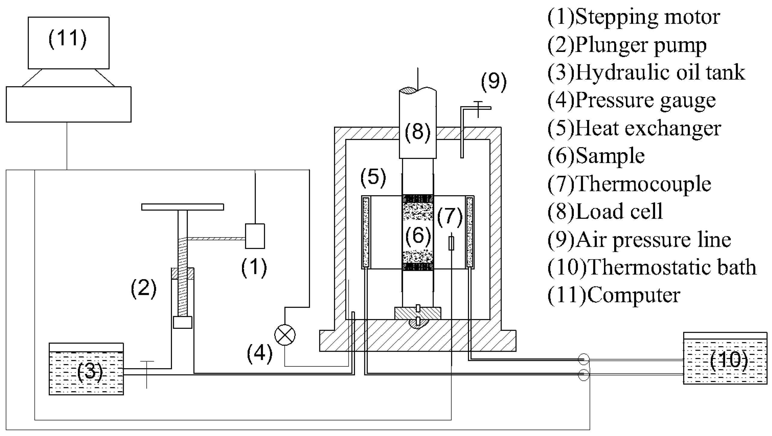
Figure 2.
Appearance of the triaxial test system.
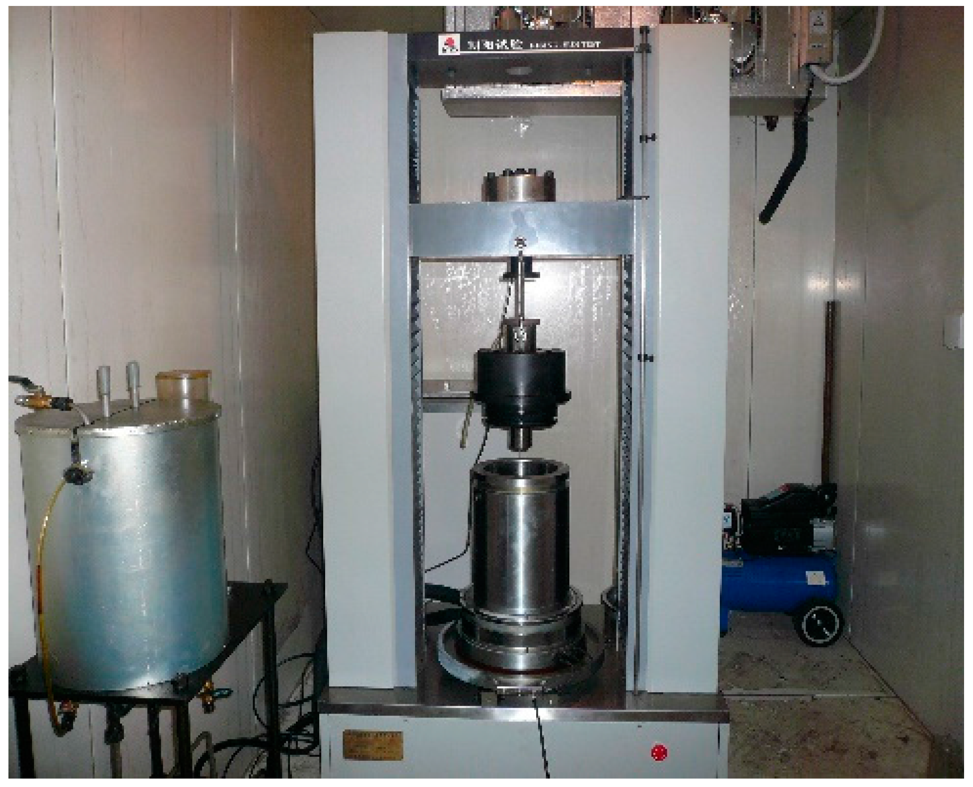
Figure 3.
Appearance of the pressure crystal device and the high pressure reaction vessel. (a) Pressure crystal device; (b) High pressure reaction vessel.
Figure 3.
Appearance of the pressure crystal device and the high pressure reaction vessel. (a) Pressure crystal device; (b) High pressure reaction vessel.

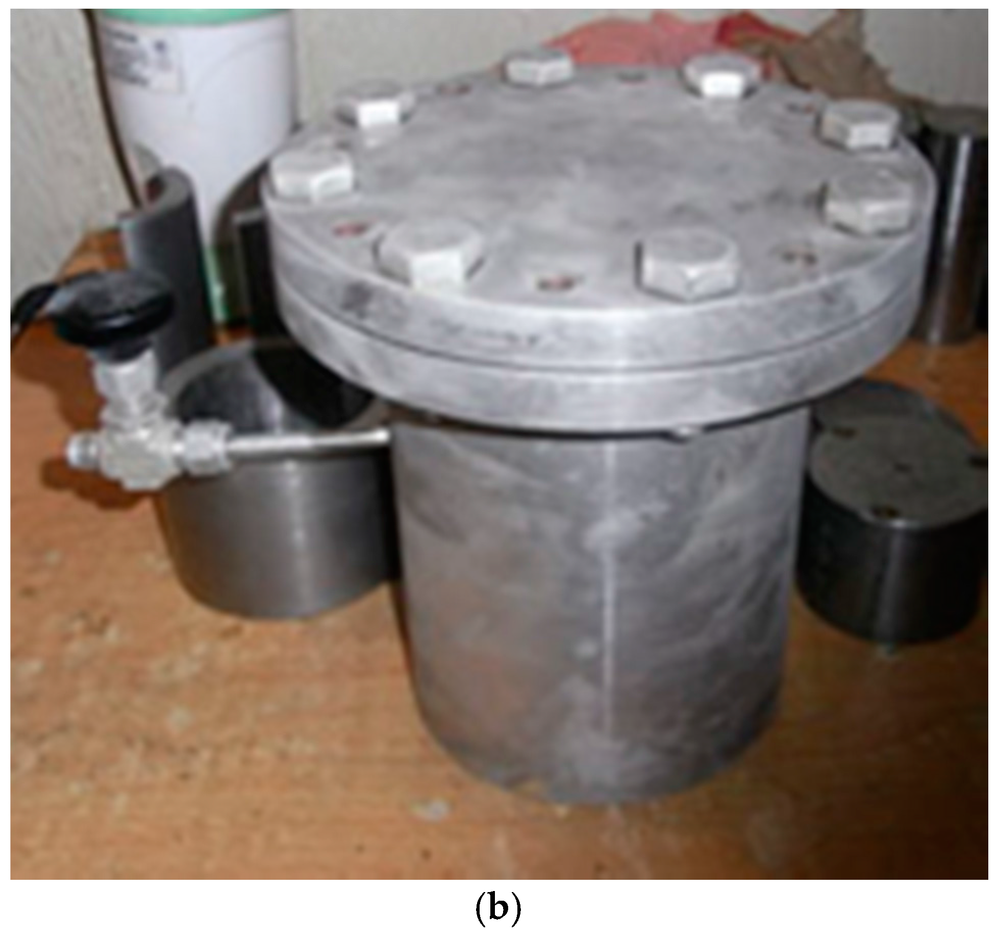
Figure 4.
Appearance of the end platens, the seals, and the rubber membrane.
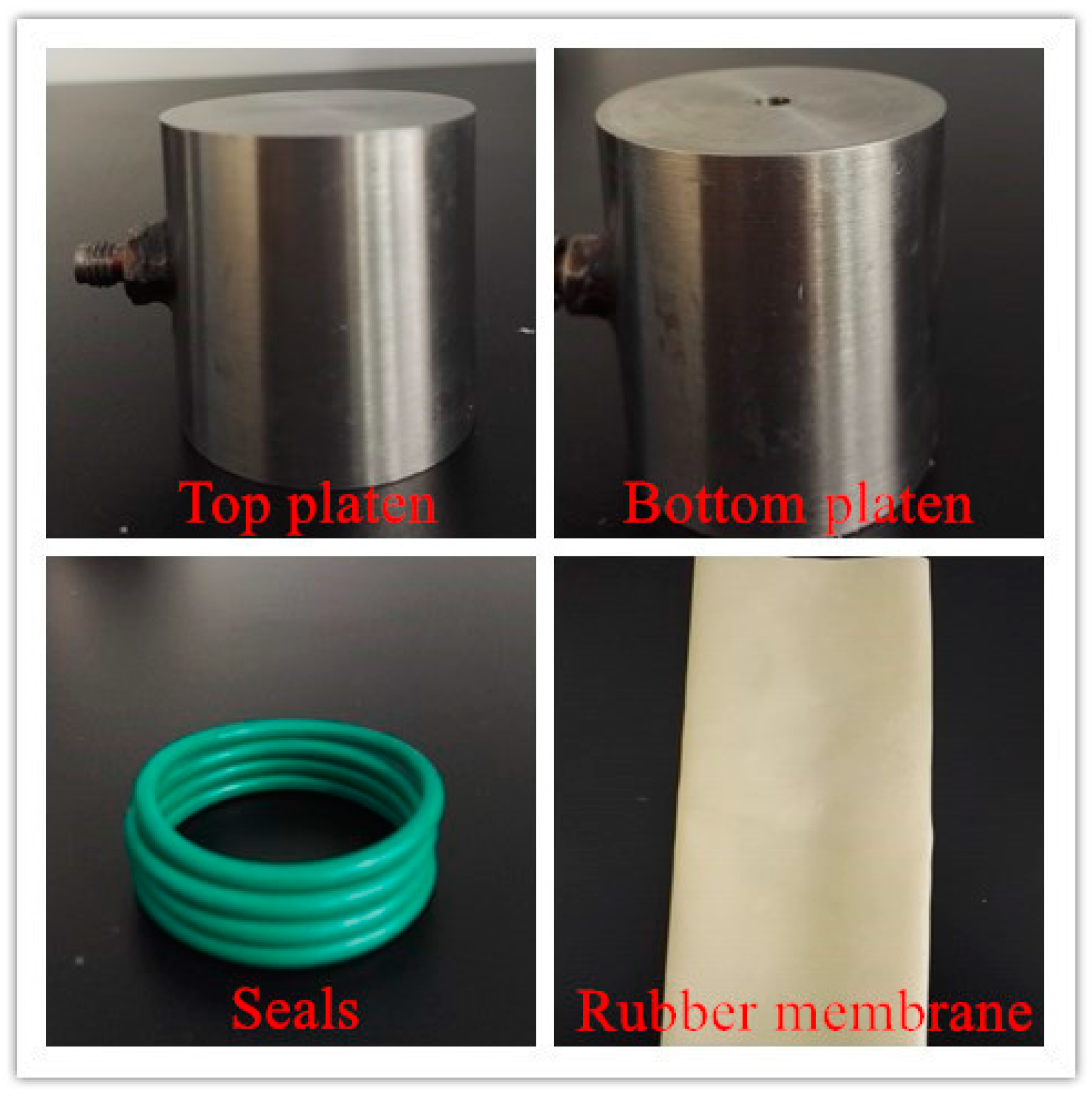
Figure 5.
Particle size distributions of sediment matrices.

Figure 6.
Samples of CH4 hydrate-bearing sediments.
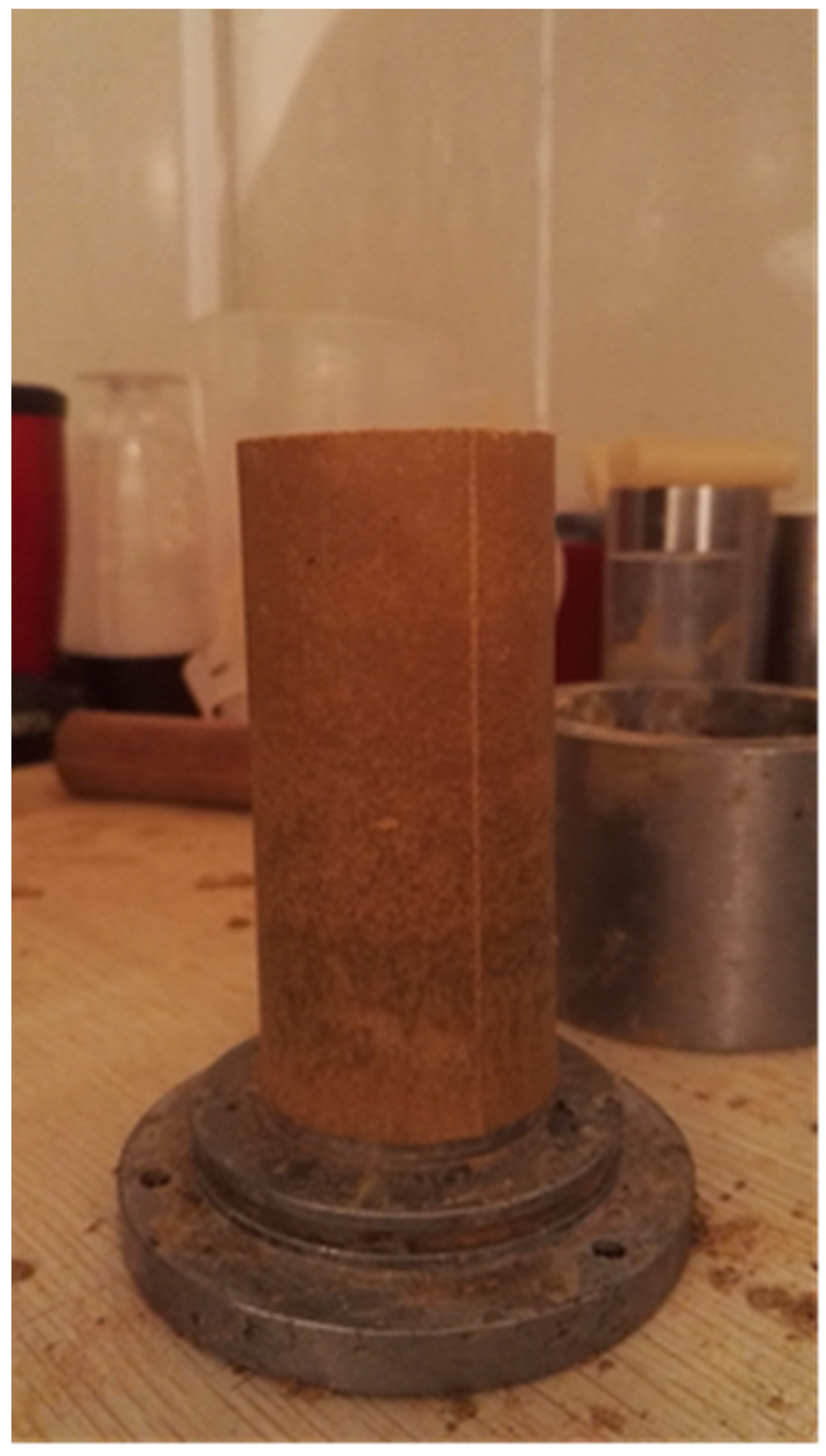
Figure 7.
The phase equilibrium of the CO2 hydrate and the CH4 hydrate.

Figure 8.
Stress-strain curves of the CH4 and CO2 hydrate-bearing sediments under different confining pressures. (a) CH4 hydrate-bearing sediments; (b) CO2 hydrate-bearing sediments.
Figure 8.
Stress-strain curves of the CH4 and CO2 hydrate-bearing sediments under different confining pressures. (a) CH4 hydrate-bearing sediments; (b) CO2 hydrate-bearing sediments.
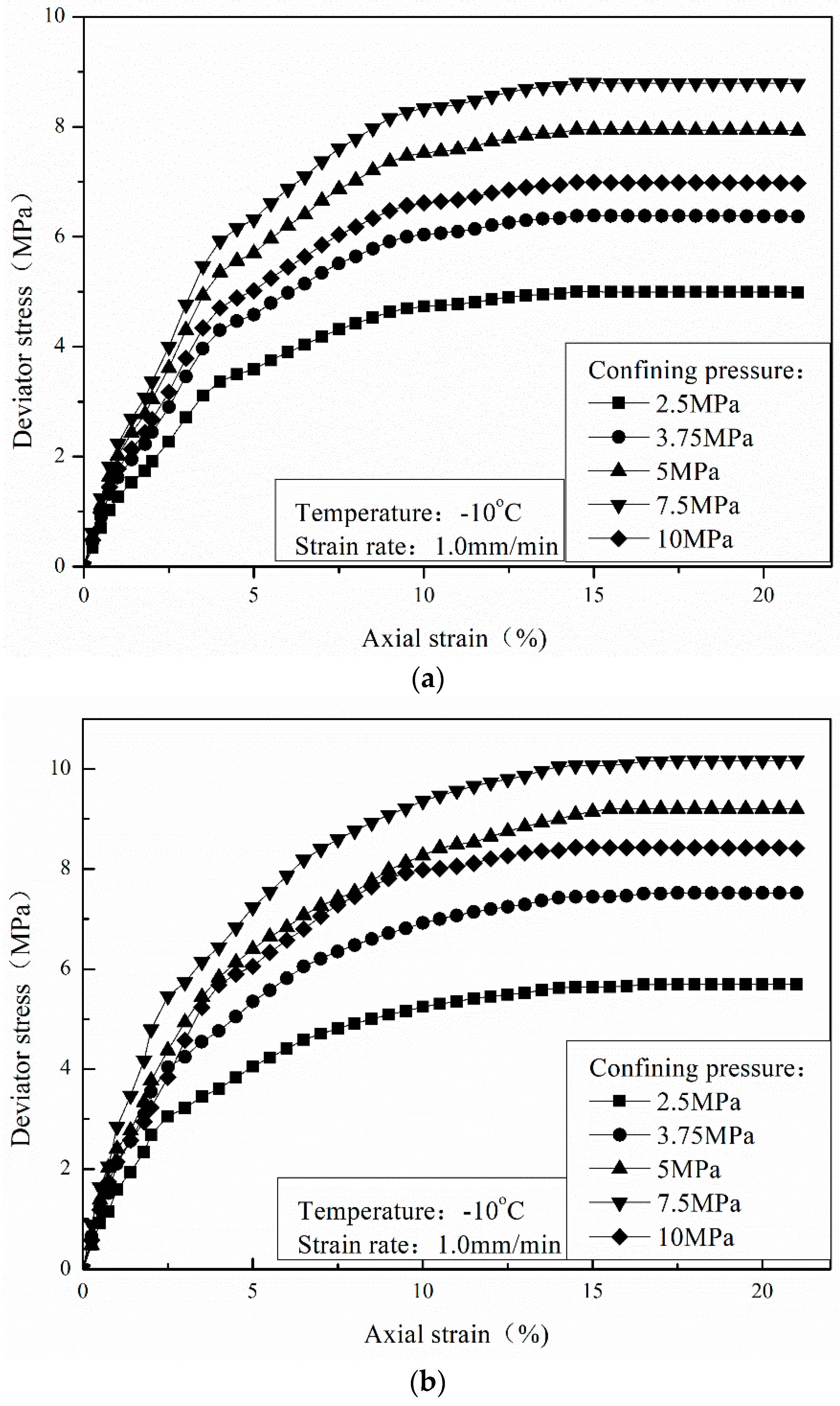
Figure 9.
Failure strength of the CH4 and CO2 hydrate-bearing sediments under different confining pressures.
Figure 9.
Failure strength of the CH4 and CO2 hydrate-bearing sediments under different confining pressures.
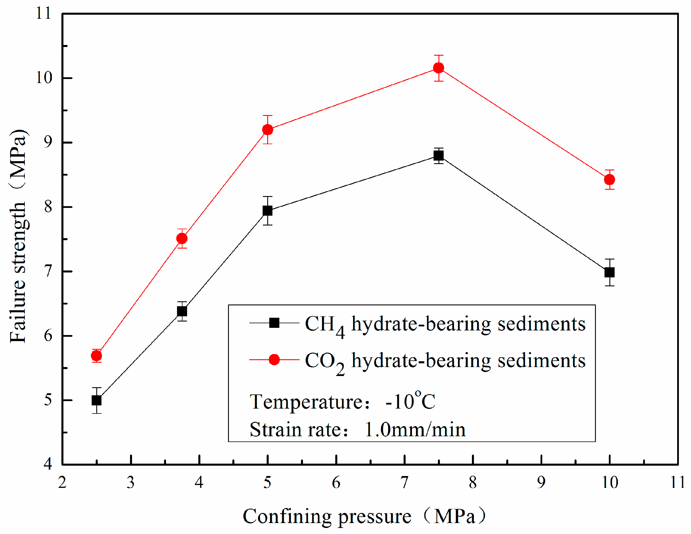
Figure 10.
Stress-strain curves of the CH4 and CO2 hydrate-bearing sediments under different temperatures. (a) CH4 hydrate-bearing sediments; (b) CO2 hydrate-bearing sediments.
Figure 10.
Stress-strain curves of the CH4 and CO2 hydrate-bearing sediments under different temperatures. (a) CH4 hydrate-bearing sediments; (b) CO2 hydrate-bearing sediments.

Figure 11.
Failure strength of the CH4 and CO2 hydrate-bearing sediments under different temperatures.
Figure 11.
Failure strength of the CH4 and CO2 hydrate-bearing sediments under different temperatures.
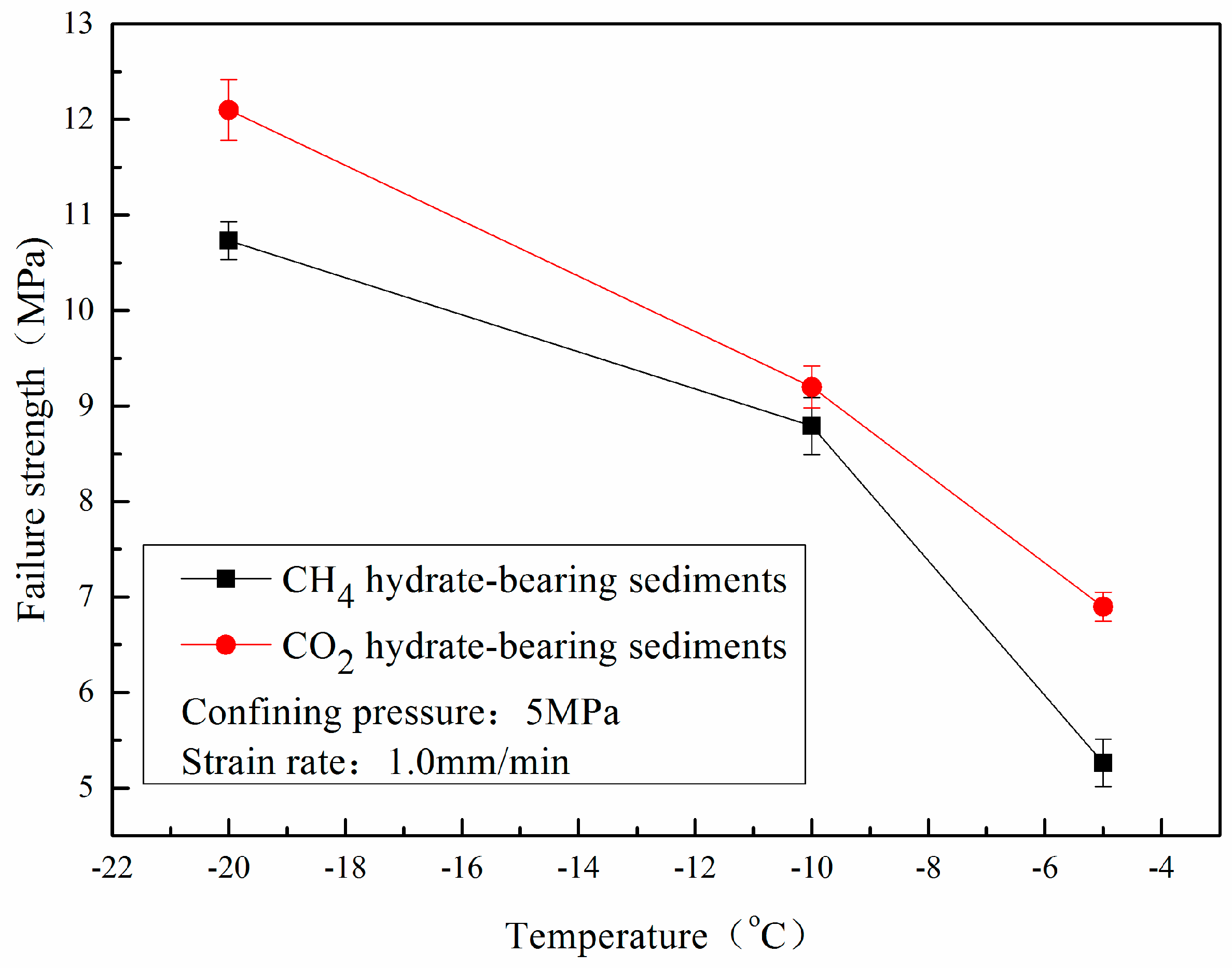
Figure 12.
Stress-strain curves of the CH4 and CO2 hydrate-bearing sediments in different sediment matrices. (a) CH4 hydrate-bearing sediments; (b) CO2 hydrate-bearing sediments.
Figure 12.
Stress-strain curves of the CH4 and CO2 hydrate-bearing sediments in different sediment matrices. (a) CH4 hydrate-bearing sediments; (b) CO2 hydrate-bearing sediments.
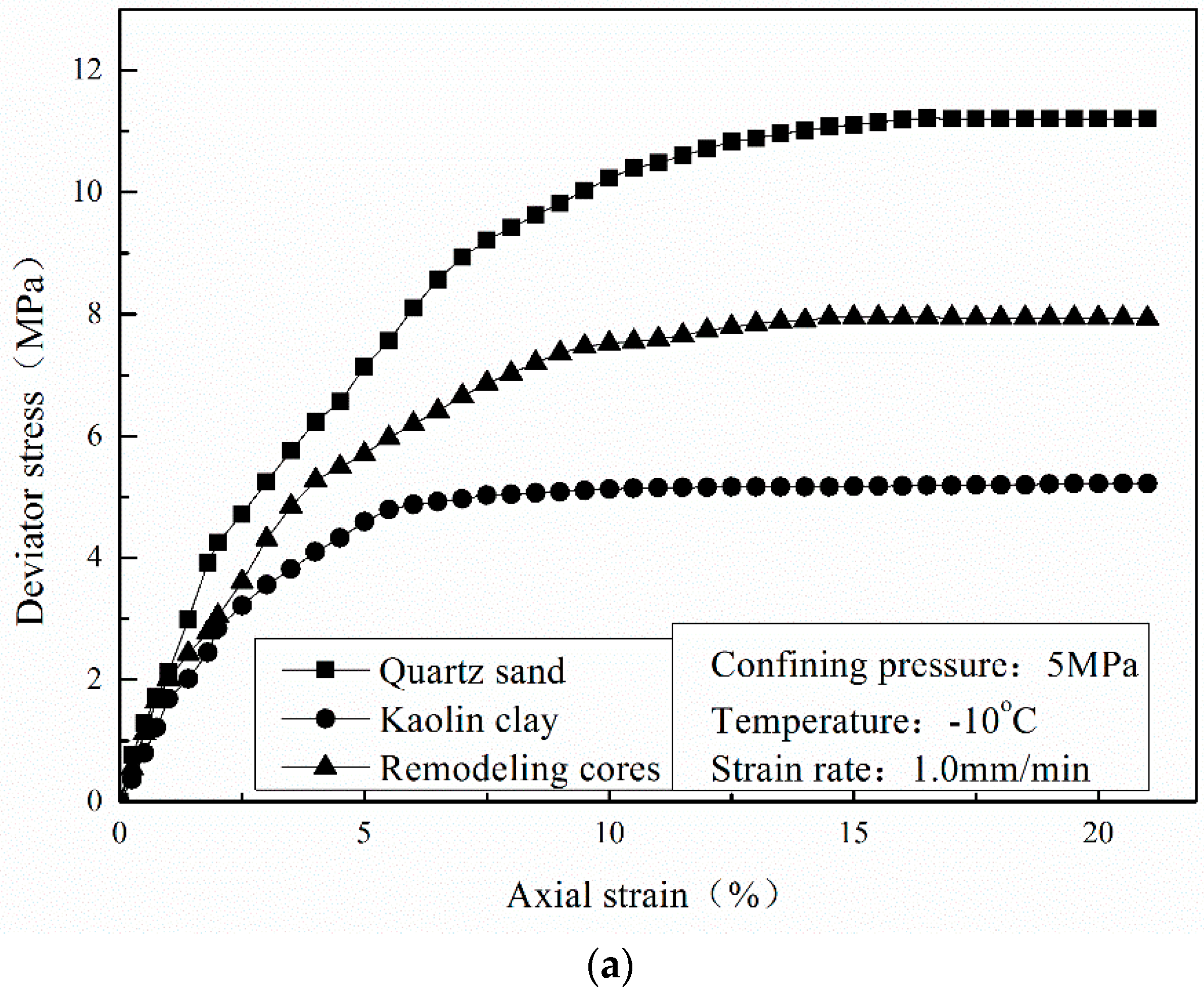

Figure 13.
Failure strength of the CH4 and CO2 hydrate-bearing sediments in different sediment matrices.
Figure 13.
Failure strength of the CH4 and CO2 hydrate-bearing sediments in different sediment matrices.

Figure 14.
Mohr’s stress circles and the envelopes of CH4 and CO2 hydrate-bearing sediments under confining pressures of 2.5, 3.75, and 5 MPa. (a) CH4 hydrate-bearing sediments; (b) CO2 hydrate-bearing sediments.
Figure 14.
Mohr’s stress circles and the envelopes of CH4 and CO2 hydrate-bearing sediments under confining pressures of 2.5, 3.75, and 5 MPa. (a) CH4 hydrate-bearing sediments; (b) CO2 hydrate-bearing sediments.

© 2017 by the authors. Licensee MDPI, Basel, Switzerland. This article is an open access article distributed under the terms and conditions of the Creative Commons Attribution (CC BY) license (http://creativecommons.org/licenses/by/4.0/).
Share and Cite
MDPI and ACS Style
Luo, T.; Li, Y.; Liu, W.; Sun, X.; Shen, S. Experimental Study on the Mechanical Properties of CH4 and CO2 Hydrate Remodeling Cores in Qilian Mountain. Energies 2017, 10, 2078. https://doi.org/10.3390/en10122078
AMA Style
Luo T, Li Y, Liu W, Sun X, Shen S. Experimental Study on the Mechanical Properties of CH4 and CO2 Hydrate Remodeling Cores in Qilian Mountain. Energies. 2017; 10(12):2078. https://doi.org/10.3390/en10122078
Chicago/Turabian StyleLuo, Tingting, Yanghui Li, Weiguo Liu, Xiang Sun, and Shi Shen. 2017. "Experimental Study on the Mechanical Properties of CH4 and CO2 Hydrate Remodeling Cores in Qilian Mountain" Energies 10, no. 12: 2078. https://doi.org/10.3390/en10122078
Note that from the first issue of 2016, this journal uses article numbers instead of page numbers. See further details here.