Design and Selection of Innovative Primary Circulation Pumps for GEN-IV Lead Fast Reactors
by
 , ,
, ,
Walter Borreani
1,2,3 ,
,
Alessandro Alemberti
2,
Guglielmo Lomonaco
1,3,* ,
,
Fabrizio Magugliani
2,† and
Paolo Saracco
3 1
Genoa Nuclear Research Group (GeNERG)—Department of Mechanical Engineering, Energy, Production, Transport and Mathematical Models (DIME)/Division of Thermal Engineering and Environmental Conditioning (TEC), University of Genova (UNIGE), Via All’Opera Pia 15/A, 16145 Genova, Italy
2
Ansaldo Nucleare, Corso F. M. Perrone 25, 16152 Genova, Italy
3
National Institute for Nuclear Physics (INFN), Via Dodecaneso 33, 16146 Genova, Italy
*
Author to whom correspondence should be addressed.
†
Current address: E4 Computer Engineering, Via Martiri Della Libertà 66, 42019 Scandiano (RE), Italy.
Energies 2017, 10(12), 2079; https://doi.org/10.3390/en10122079
Submission received: 30 September 2017
/
Revised: 19 November 2017
/
Accepted: 21 November 2017
/
Published: 7 December 2017
(This article belongs to the Section L: Energy Sources)
Abstract
:Although Lead-cooled Fast Reactor (LFR) is not a new concept, it continues to be an example of innovation in the nuclear field. Recently, there has been strong interest in liquid lead (Pb) or liquid lead–bismuth eutectic (LBE) both critical and subcritical systems in a relevant number of Countries, including studies performed in the frame of GENERATION-IV initiative. In this paper, the theoretical and computational findings for three different designs of Primary Circulation Pump (PCP) evolving liquid lead (namely the jet pump, the Archimedean pump and the blade pump) are presented with reference to the ALFRED (Advanced Lead Fast Reactor European Demonstrator) design. The pumps are first analyzed from the theoretical point of view and then modeled with a 3D CFD code. Required design performance of the pumps are approximatively around an effective head of 2 bar with a mass flow rate of 5000 kg/s. Taking into account the geometrical constraints of the reactor and the fluid dynamics characteristics of the molten lead, the maximum design velocity for molten lead fluid flow of 2 m/s may be exceeded giving rise to unacceptable erosion phenomena of the blade or rotating component of the primary pumping system. For this reason a deep investigation of non-conventional axial pumps has been performed. The results presented shows that the design of the jet pump looks like beyond the current technological feasibility while, once the mechanical challenges of the Archimedean (screw) pump and the fluid-dynamic issues of the blade pump will be addressed, both could represent viable solutions as PCP for ALFRED. Particularly, the blade pump shows the best performance in terms of pressure head generated in normal operation conditions as well as pressure drop in locked rotor conditions. Further optimizations (mainly for what the geometrical configuration is concerned) are still necessary.
1. Introduction
Although Lead-cooled Fast Reactor (LFR) is not a new concept, it continues to be an example of innovation in the nuclear field. Starting from the initial researches related to its use for naval (submarine) propulsion dating to the 1950s, Russian researchers pioneered the development of Heavy Liquid Metals (HLM) reactors. More recently, there has been increasing interest in liquid lead (Pb) or liquid Lead–Bismuth Eutectic (LBE) both critical and subcritical systems in a relevant number of Countries (e.g., [1,2,3,4]). The increasing knowledge of the thermal-fluid-dynamic properties of these heavy fluids and the selection of the LFR as one of the six system types chosen by Generation IV International Forum (GIF) [5] for further R&D fostered the exploitation of new solutions and concepts to optimize the key components to be adopted in the 300 MWth pool-type Advanced Lead Fast Reactor European Demonstrator (ALFRED) aimed at proving the feasibility of the conceptual solutions selected for the European Lead-cooled Fast Reactor (ELFR).
In this paper, starting from a previous preliminary work [6], we present theoretical and numerical results for three different designs for the Primary Circulation Pump (PCP) involving liquid lead for the considered ALFRED design (namely a jet pump, an Archimedean pump and a blade pump) and a preliminary comparative selection of the most suitable design.
The pumps are at first analyzed at design operating conditions to optimize the geometry on the basis of to the velocity triangles and then they are modeled by proper CFD simulations. The pumps are analyzed at different flow regimes to find the optimal design point maximizing the mass flow rate at operating conditions and minimizing the pressure losses at Natural Circulation (NC) conditions. This choice is due to the requirement of having a detailed 3D simulations that take into account both the specific geometry of each pump and the boundary and turbulence effects of the flow. Moreover, the use of molten lead has a relevant impact on the thermal-fluid-dynamic pump design due to the key requirements necessary to avoid erosion and stagnation effects. These requirements, along with the design specifications, dictate the geometry, reliability and performance of the pump.
2. Background
2.1. Lead as Liquid Metal Coolant for Fast Reactor
Liquid metals are used as coolant for fast reactors (FRs), where neutrons generated during the fissions chain are not moderated. Lead and its alloys have been proposed as cooling media; LBE was chosen as the coolant for some submarine reactors (Alpha class) in the former Soviet Union; more recently there has been renewed interest in lead and LBE coolants for civilian FRs. In these nuclear power plants (NPPs), fast neutrons support the chain reaction because, looking at the lead cross sections, it is very small for absorption and high for scattering (also thanks to its high atomic number): the final discharge fuel burnup is high since the so called “closed cycle” [7] can be implemented, thus substantially reducing the accumulation of highly radioactive waste.
Concerning safety features, lead has high boiling point, very low vapor pressure and high γ shielding capacity; additionally it retains fission products (e.g., Cs and I) released from the core in case of cladding failure and it does not react violently with water and air. Moreover, lead has high thermal capacity and heat transfer coefficients: the very low likelihood of damage to the core is enforced by the above cited characteristics. In the following Table 1, a comparison is shown between the main thermo-physical proprieties of water (at typical operating pressure of a pressurized water reactor), sodium and lead.
Lead shows some advantages compared with water and sodium. It has a significantly higher boiling point with two main consequences:
- LFR can, in principle, operate at higher temperature than SFR, increasing thermal efficiency and ensuring a substantially higher safety margin
- Primary system pressurization is not necessary, as it must be done in the case of water; safety of the system is improved as the probability of loss of coolant accident is practically eliminated.
Furthermore, lead does not react with water or air, at variance of sodium which spontaneously ignites in air and reacts explosively with water; sodium therefore requires an intermediate coolant loop (usually implemented via a primary and a secondary loops) with higher costs and lower thermal efficiency.
Looking at sustainability, lead is available in relevant quantities also in a scenario with a high number of reactors in use.
Despite all these advantages, lead as coolant for a fast reactor has also some disadvantages and problems still unresolved. Lead is more corrosive to steel than sodium. Moreover, the melting temperature of sodium is 97.72 °C, lower than lead’s temperature, and this could bring more difficulties in the case of solidification of the coolant if unlikely reactor should operate at low temperature.
Hence, the properties that make lead suitable for being used as coolant in fast reactors are:
- It does not react with air and water, therefore the intermediate loop can be removed, and the steam generators can be installed directly within the Reactor Vessel (RV). In case of coolant losses, the requirements will be less stringent
- Very high boiling point, hence the presence of voids or core uncover are reduced
- Density greater than the fuel, therefore, a core catcher is not required to deal with a core melting accident: there is no risk of return to criticality after meltdown
- Low absorption cross section and low moderating power, therefore a very compact fuel assembly is not necessary, then the passage section in the fuel assembly is large enough to maintain a low speed, low pressure drop, reduce pumping power and to obtain a large capacity to sustain NC.
The use of lead (or similar lead alloys) as the coolant in advanced FRs needs of high-temperature operation and requires structural materials qualified for these reactors. Known structural alloys like the ferritic-martensitic T91 and the austenitic stainless steel 316L have been an initial choice, but they have the problem to undergo severe dissolution attacks.
As known, corrosion is one phenomenon to be investigated for the qualification of a structural material. Other important phenomena are erosion, material failure under static loading (e.g., brittle fracture) and failure under time-dependent loading (e.g., fatigue and creep); this is the most important effect that limit the velocity at the tip of the blade in the axial pump configuration, with the consequent choice of a very low rotational speed with respect to the conventional industrial application.
2.2. ALFRED (Advanced Lead Fast Reactor European Demonstrator)
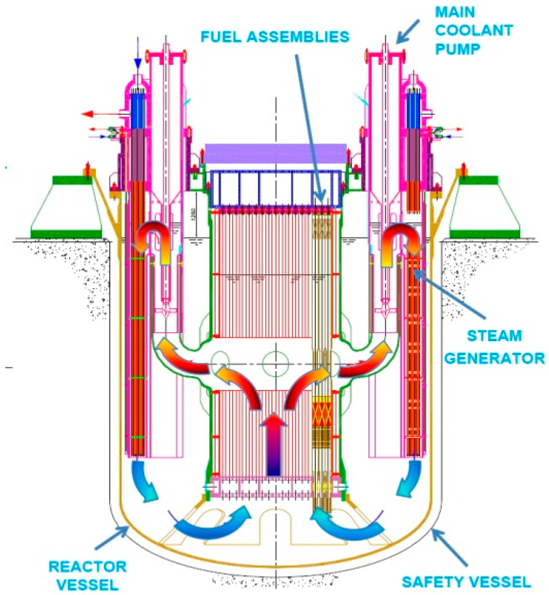
As part of the 7th Framework Program Lead-cooled European Advanced Demonstration Reactor (LEADER) project, the conceptual design of a lead-cooled fast demonstrator reactor, ALFRED has been carried out. The conceptual configuration of ALFRED is shown in Figure 1 [6]; its aim is to develop a fully representative, scaled demonstrator of the industrial European Lead Fast Reactor (ELFR, also defined in the LEADER project), representing a guideline for its design and construction in terms of costs, safety, components and technologies. The ALFRED key parameters are reported in Table 2 [6].
Because of the requirements of inspection and removability for all the main reactor components, all of them are specifically designed to be removable (independently and separately) from the reactor.
The design of the (mechanical) PCPs is such that they are enclosed in hot manifolds allowing for their removal from inside the inner vessel and contributing to the compactness of the plant. Different configurations for the key components of ALFRED are under evaluation, including a new design and arrangement of the steam generators, of the auxiliary equipment and of the PCPs, in order to find the optimum both at the single component and at the whole reactor. Concerning the PCP development, various configurations are presently under evaluation: particularly, this paper presents the computational evaluation of three different designs, focusing on the most promising one.
Two possible architectural solutions are proposed in this work for the pump installation: pull-type or push-type primary pump. In the first configuration, the suction side of the pump is placed at the top and the discharge side at the bottom, vice versa for the ‘pull’ type (see Figure 2).
3. Results
Generally, a pressure based incompressible calculation has been performed, with isothermal and turbulent flow modeling. For this purpose, no investigations were performed in terms of temperature influence, because the maximum velocity and the pressure drop when the pump is off are the limiting constraints: the influence of different operating temperatures is very small so that in the model adopted all the wall boundaries conditions are settled as adiabatic, and the lead properties are imposed constant and calculated at the core outlet fluid flow mean temperature, equal to 480 °C.
The equations suggested for the calculations of the molten lead properties are reported in [8] and in particular, in Table 3 has been reported those for density and dynamic viscosity.
Regarding the turbulence model, the k-ω SST [9] was adopted for all the calculations performed. The selected model allows the creations of different structure of mesh at the wall, with a different resolution of the near-wall flow nodes equations depending on the y+ values, that shows in which of the sublayer (viscous, buffer or log-law layer) the nodes are placed (see [10,11] for more details). Considering the non-implementations of ad-hoc wall functions for liquid metals in ANSYS FLUENT® 17.0, and preferring the near wall flow resolutions requiring a y+ value of less than 1, the grid and the mesh size increase the computational expense of the calculation. Working with liquid lead, the computational grid was therefore created with a very fine mesh at the blade and recirculating/critically zones, while in the straight part of the domain a larger size of the cells (normal to the wall surface) was selected, in order to limit the computational weight of the mesh (around 32 Gb of RAM).
The entrainment of cover gas in the flow is a possible issue of all systems designs characterized by the existence of free levels. This can be taken into account and evaluated by specific CFD calculations using a multiphase approach (e.g., VOF), as already used in the steam generator design calculation reported in [12]. Such phenomena are strongly dependent on the specific location of the pump in the primary system and have not been directly addressed in this work being the object of a separate research branch.
The optimal performances search for each geometry investigated has been conducted with two general goals:
- (a)
- The minimization of maximum velocity on the blade or in the neck section: at the driver tip for jet pump and on the peripheral sections or at the tip of the blade in the crew and semi-axial configurations
- (b)
- The minimization of the pressure loss at pump off in locked rotor conditions: this is considered a very important requirement to allow the establishment of the natural circulation; for some configurations (like the jet pump) the issue is solved at design level but, for the screw and the blade pump, a particular design of the blade and an accurate sizing of the inlet and outlet section is required to minimize pressure losses in natural circulation.
Obviously, for each pump further optimizations are developed, in terms of efficiency or to avoid recirculating zones in particular sections, although the primary design requirements are based on the previously exposed mass flow rate and required head in conjunction with the structural and safety consideration based on velocity and pressure losses. In the following, through investigations of these aspects are presented.
3.1. Theoretical and CFD Simulation of the Jet Pump
The reasons behind the detailed analysis of the jet pump are related with the safety requirements of a GEN-IV reactor PCP: to enable the coolant NC also in accidental scenarios, to guarantee the heat removal from the core even in the case of failure of any (Design Basis Scenario) or all (Station Black-out Scenario) of the 8 PCPs. The jet pump geometry is particularly suitable for enabling the NC since there are no moving parts and obstacles (such as blades or screws) inside the pump that could hinder the fluid flow.
This paragraph presents a computational model of a jet pump evolving liquid lead as PCP for a GEN-IV LFR nuclear power plant adopting the ALFRED operational conditions, by assessing its behavior at various mass-flow rates and different geometries, and optimizing its performance through an in-depth 3D CFD analysis based on the established package ANSYS Fluent [13]. To complement the 3D CFD analysis in the design and optimization phases, the 1D Jet Mixer feature a system code has been used [14]. In [15] an in-depth analysis of the jet pump evolving molten lead for ALFRED is presented.
The necessity to provide a driver flow and the requirement to extract the pump from the reactor enforces a re-design of the whole reactor with respect to the conceptual design reported in Figure 1. The geometrical layout of the reactor for the jet pump envisions a driver flow flowing downward, the suction-side flow entering the jet pump close to the free surface and the jet pump discharging in a pressure chamber immediately below the core. The geometrical layout and a comparison with the conceptual design are reported in Figure 3.
Because of the unavailability of an extensive set of experimental data for jet pumps evolving liquid lead as working fluid, as a first approach a jet pump evolving water as working fluid has been modeled according to a classical theoretical model [16] to validate the simulation model by comparing the theoretical predictions with a set of experimental data for a water jet pump [17], get more sensibility about the jet pump behavior, and analyze how the operational parameters affect its features. The results of the theoretical model for the jet pump evolving water matched excellently the experimental data with an averaged error less than the 5%, as reported in [6], validating the approach and the modeling technique. Furthermore, a set of simulation that investigate a Venturi nozzle (very similar to the Jet pump) evolving liquid lead, and clearly shown a very good agreement between CFD and experimental results is reported in literature [18], with an averaged error greater than the simulations with water but which does not exceed the 8% in the steady calculations.
The jet pump evolving liquid lead as working fluid and designed to be located in ALFRED has the following constraints:
- The pump is placed inside the pump tube, which has a diameter of 0.6 m and a longitudinal length of 8 m
- The pump operates with lead entering the tube at 400 °C from the top, near the free surface of the pool, and/or from holes in the upper part of the tube
- The pressure at inlet and outlet are affected by the hydrostatic head
- The pump must ensure a head of at least 1.5 bar to provide the required coolant circulation and compensate the pressure losses in the circuit
- The volumetric mass flow rate must be 0.31 m3/s (3274 kg/s) at each pump
- Proper provisions shall be applied to minimize the pressure loss at NC conditions.
Using the hydrodynamic similarity and imposing the thermo-mechanical properties for lead [8] in the theoretical correlations [16], a first-guess geometry for the lead jet pump (Figure 4a) and for the flow patterns (Figure 4b) have been obtained.
The viscous, isothermal and adiabatic features have been selected for the physical model, using the k-ε model for turbulence and the Standard Wall Function as Near Wall Treatment. Concerning the Near Wall Treatment, the range 30 ÷ 300 has been selected for y+, as suggested in literature [15]. Furthermore, steady state condition has been simulated. The Boundary Condition of Pressure Inlet has been set for the inlet suction zone, the Boundary Condition of Pressure Outlet has been set for the outlet diffuser zone and a Boundary Condition of Inlet Mass flow rate has been set for the driver zone. Two criteria have been chosen to assess the quality of the simulation:
- The inlet mass flow rate at suction: this parameter has been evaluated until it remains constant
- The convergence of the residuals, evaluating the residuals trend during the simulation: it is considered acceptable a convergence of at least 1.0 × 10⁻⁵.
Starting from the first-guess configuration, a parametric CFD study has been carried out varying the geometrical and physical parameters of the pump. The final target of the parametric study is to reach an optimized configuration for the jet pump, i.e., to elaborate the mass flow rate, to generate the pressure head, to obtain a static pressure at driver inlet as low as possible to facilitate the design of the driver’s centrifugal pump, to maintain the velocity at the tip of the driver lower than 15 m/s (and in general as low as possible), to have a uniform velocity profile at the diffuser outlet (with a maximum value equal to 3.5 m/s) and finally to respect the geometrical limitations and to maintain a good performance in terms of N, defined as:
and of the ratio M between the mass flow rate of the fluid at suction vs. the mass flow rate at driver ):
Several different geometries and Boundary Conditions have been tested in the parametric study (reported in [15]). The optimal performance, according to the geometrical specifications in terms of maximum size allowed, has been achieved at the conditions reported in Table 4, compared with the reference case derived by the theoretical design with the water jet pump parameters: the optimal configuration has been reached essentially increasing the diffuser length and the nozzle diameter.
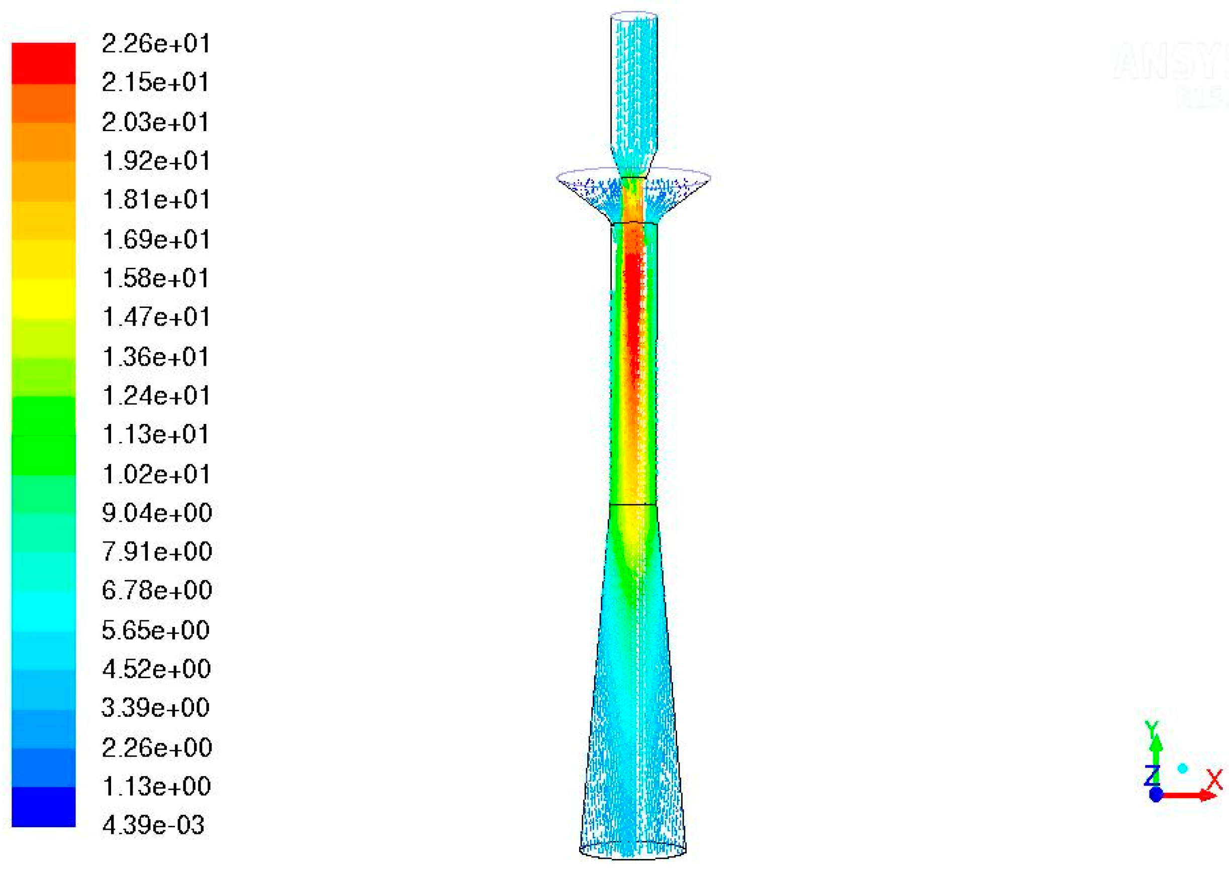
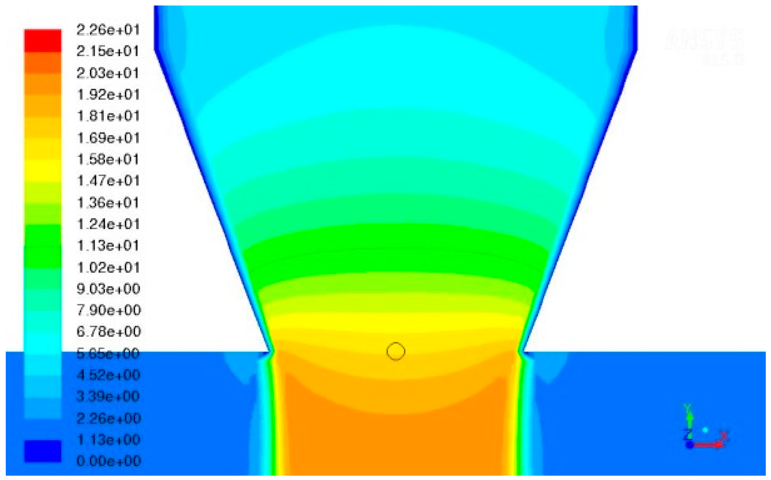
The velocity (magnitude) vectors and the contour plot of the velocity (magnitude) in the mid-plane section of the jet pump are shown in Figure 5 and Figure 6, respectively.
While the jet pump meets the requirements, two major problems prevent its use in ALFRED:
- The liquid lead velocity of 15 m/s at the driver’s tip. While present technology supplies various surface treatments to deal with the erosion phenomena caused by lead, the long-term sustainability of a jet pump working with a driver requiring a maximum velocity of 15 m/s is at least questionable. It is not currently possible to give assurance that this device could respect the durability in these conditions without structural damages
- An operative pressure of at least 23 bar for the driver. The authors are not aware of any general-purpose or especially engineered pump elaborating liquid lead and producing such a pressure. Possibly, the design of such a pump is of the same order of technological difficulty as the jet pump it is supposed to drive.
3.2. Theoretical and CFD Simulation of the Archimedean Pump
As with the jet pump, the reasons behind the detailed analysis of an Archimedean pump as primary pump for a nuclear reactor are related with the safety requirements of a GEN-IV reactor:
- Enabling the coolant NC in accidental or only locked rotor conditions
- Removing the heat from the core even in the case of failure of any (Design Basis Scenario) or all (Station Black-out Scenario) of the eight pumps.
The objective of the modeling of the Archimedean pump is to determine if the device can generate the required increase of pressure at normal operation conditions and if the pressure loss in NC conditions does not prevent the establishment of the NC itself.
The Archimedean (or screw pump) is the oldest type of rotating pump. Even though this pump was invented in ancient times, it has been improved throughout time and still today it is widely used. The Archimedean pump is used mainly for moving fluids from a lower to higher level. In the specific application for ALFRED, the Archimedean pump should have the same diameter as the jet pump, pumping the liquid lead downward and having the suction side in the pool right below the free surface. The detailed 3D CFD analysis has been performed using the established package ANSYS CFX [13]. In [19] an in-depth analysis of the Archimedean pump evolving liquid lead for ALFRED is presented.
The same requirements as with the jet pump have been applied: the pump is required to evolve 6450 kg/s of mass flow rate (the reactor’s geometry using the Archimedean pump envisioning 4 Main Circulation Pumps) and to generate 1.5 bar of differential pressure [6]. The imposed external constraints (due to reactor geometrical design and/or compatibility between lead and structural materials) of the design are:
- Rotational speed: the velocity inside the pump shall not exceed 10 m/s, due to erosion phenomena
- Pump duct’s diameter: the diameter shall be smaller than 1.2 m, to limit the diameter of the vessel, that contain each component
- Duct’s pump length: about 5 m from the pool’s free surface to the location of the impeller, due to safety requirements in terms of possible entrainment of gas in the flow, which in the case this gas reaches the core it could produce unexpected positive reactivity peak.
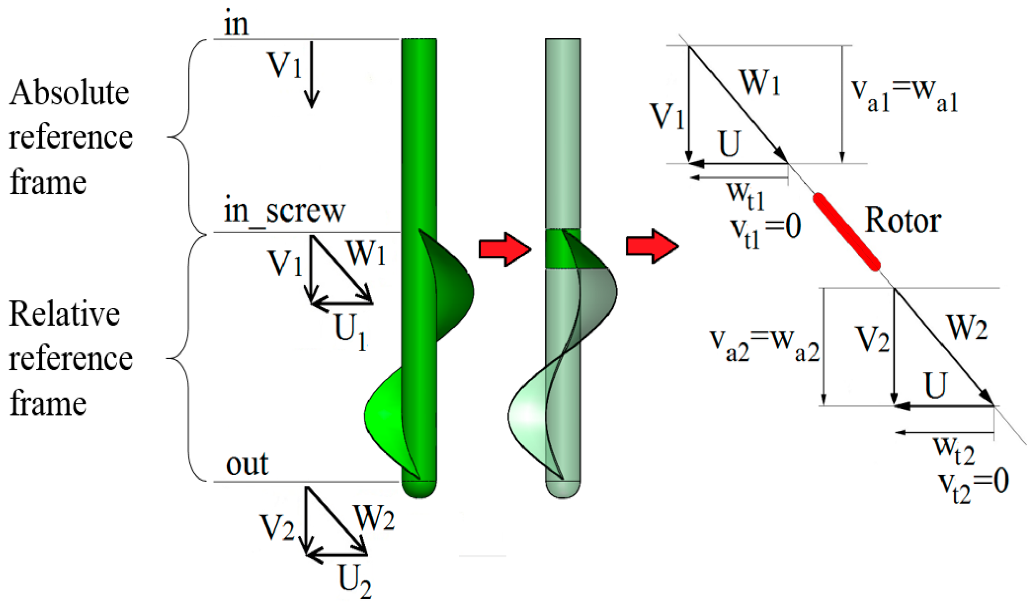
Figure 7 shows that, from the kinematic point of view, the traditional Archimedean pump with straight cylindrical beam can be considered as an axial pump with straight blades. From a theoretical analysis it can be demonstrated that, this pump cannot generate work because the velocity triangles in the sections in screw and out are not different. Indeed, in the non-viscous case and according to the canonical equation [19], if the velocity triangle does not change between the inlet and outlet sections the (total and static) pressure remains unchanged. So, in order to generate the required increase of pressure, the pumping device has to deflect the flow field at outlet (i.e., the velocity triangle at the out section) with respect to the inlet conditions (i.e., the velocity triangle at the in section).
There are two viable possibilities to deflect the flow between the in screw and out screw sections:
- By deflecting the flow via a change of the hub diameter of the screw pump (Figure 9). Doing so, the flow increases its absolute velocity moving from the section in bulb to the section in screw. Then, according to the canonical equations [19], the static pressure decreases in this portion of the pump, although passing from the section in screw to the section out screw the static pressure increases more than the previous decrease. So, this Archimedean pump with variable hub diameter can generate the required increase of pressure.
Both geometries present an original design, which, at the best of Authors’ knowledge, have not been analyzed before as per the use in NPPs. Because of manufacturability considerations with respect to the variable pitch screw, this analysis focused on the fixed-pitch screw pump with variable diameter hub. An optimization study has been performed [19] for many geometries and Boundary Conditions and the results for the optimal design, meeting the specifications and the Boundary Conditions, are presented hereunder.
In a very complex geometry such as the variable diameter hub, screw pump, each parameter (e.g., the length/angle of each variable diameter hub, the rotational regime (RPM), the pitch of the helix/angle of attack) has a major effect on the pump performance and all of them should be optimized together to reach the optimal performance.
A rotational speed of 315 RPM has been determined to represent the optimal trade-off between the need to have a low peripheral velocity and the need to transfer energy to the fluid preventing any flow separation, where the latter is also dependent on the length of the hub from the section out_screw to the section out. The differential static pressure for the new design is 1.2 bar while the differential total pressure is 2.2 bar.
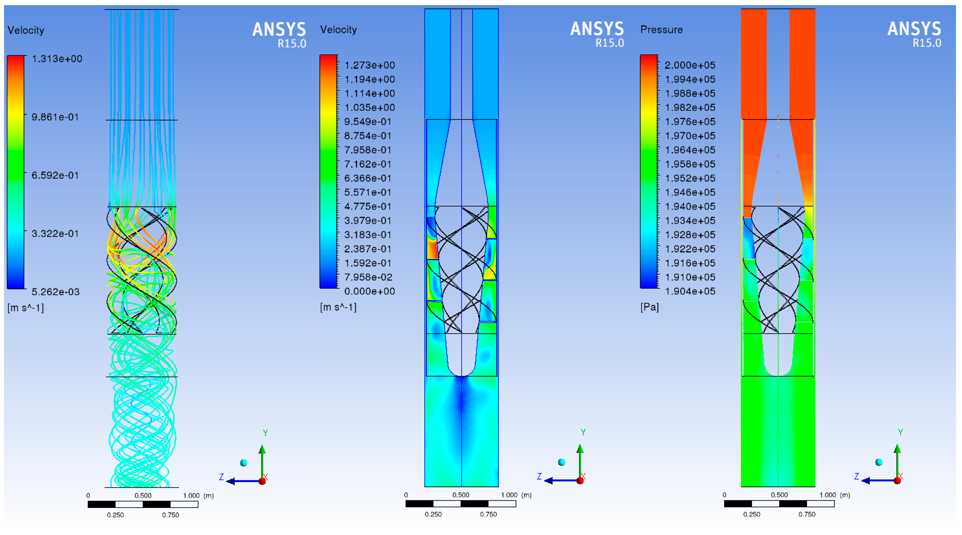
The flow field at design point is shown in Figure 10. The differential total pressure vs. the mass flow rate curve for the optimal geometry simulations in off-design conditions is shown in Figure 11.
As stated above, a key requirement for the design of the pump is to not prevent or to impairing the establishment of the flow at NC conditions. Therefore, a major emphasis has been applied to combining a design maximizing the energy transferred to the coolant in Normal Operation Conditions and minimizing the pressure loss at NC conditions. The pressure loss of the optimal design of the pump is 0.04 bar at a NC flow rate of 644 kg/s. Figure 12 shows the key characteristics of the flow at NC conditions. Figure 13 shows the velocity streamlines on the frusto-conical surface of the rotor in NC (off-design) conditions. In spite of a non-negligible change in the mass flow rate, the flow field does not show any detachment from the surface, so minimizing any undesired performance degradation.
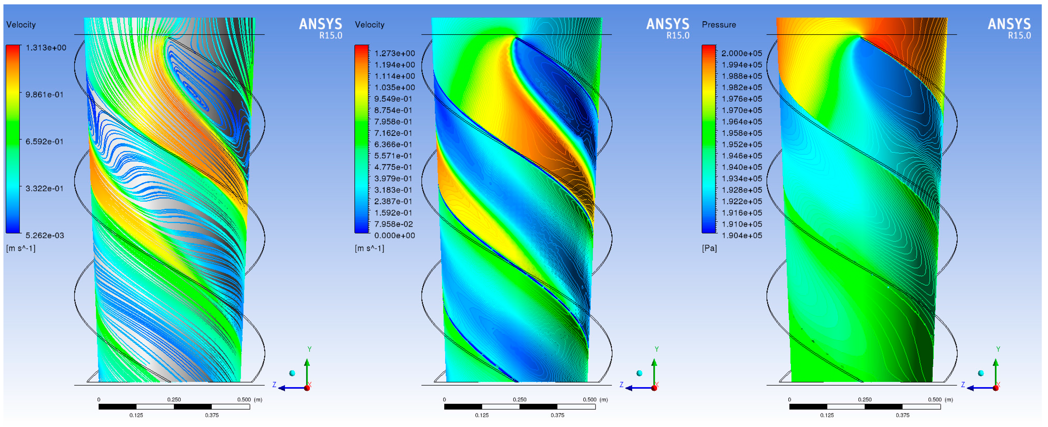
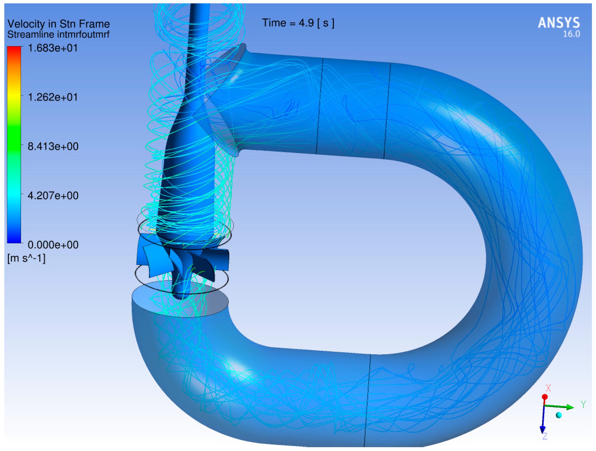
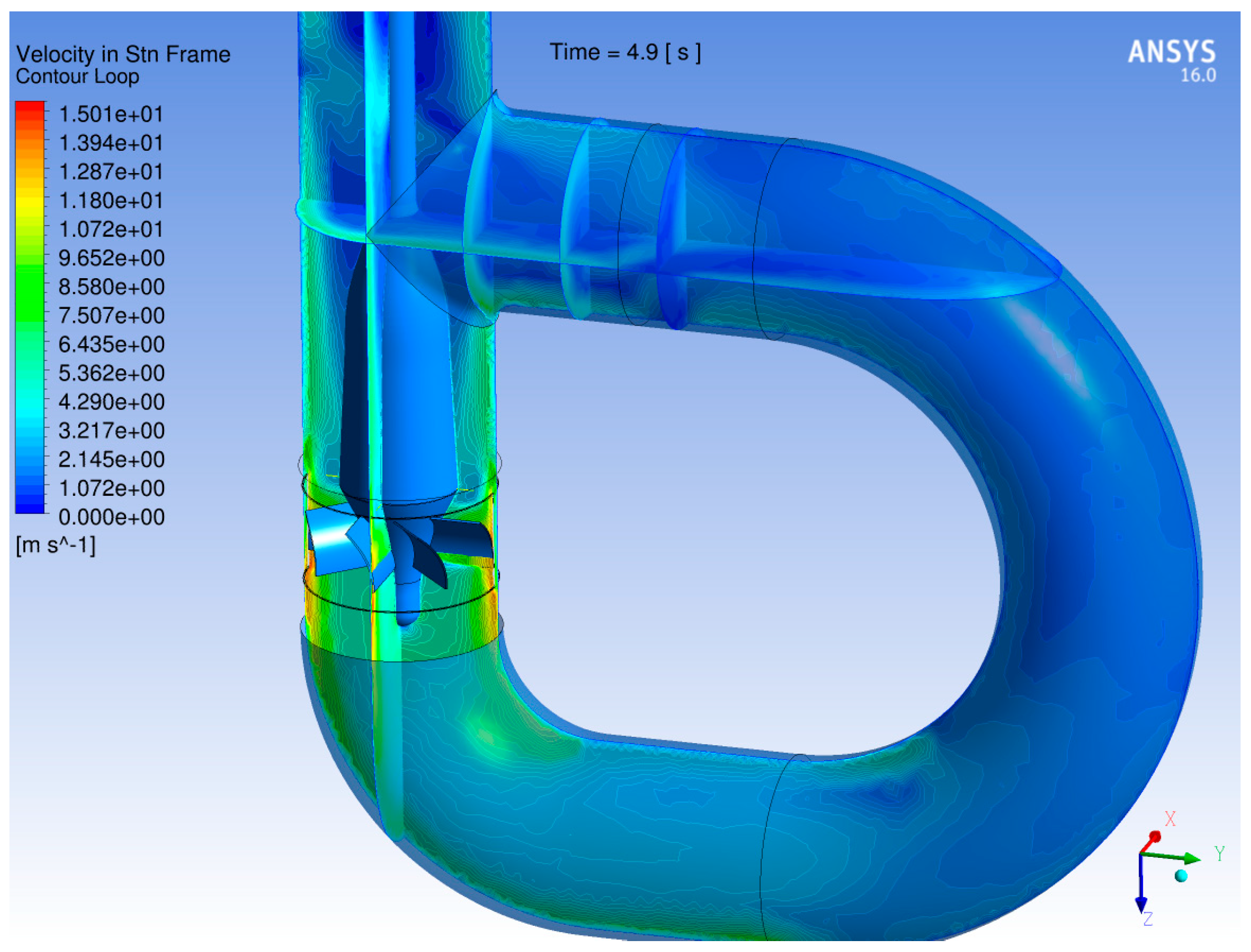
In order to ensure the independence of the results from the inlet and outlet boundary conditions a simulation including the pump in a loop has been performed: this case has been developed in ANSYS Fluent because a model prepared with this code has already been available. The layout is shown in the following picture. This set of simulation has been performed with the Sliding Mesh Model: while performing, the cell zones slide (i.e., rotate in this case) relative to another along the mesh interface in discrete steps, and the solution is time-accurate and the solver is able to model rotor/stator interactions (see [13] for further details). The sliding mesh model is the most accurate method for simulating flows in multiple moving reference frames, but also the most computationally demanding.
In this model, there are not inlet and outlet section, hence the inlet and outlet boundary conditions are not required, and the simulation is performed only setting the stationary domain in the loop and the rotating domain around the blades (as shown in Figure 14). The red surface in the left part of the loop is necessary to simulate a concentrated pressure drop, implemented into the software as a porous jump. By changing the pressure jump coefficient one can vary the pressure losses of the loop: this makes it possible to define the characteristic curve of the pump.
The following Figure 14 show the results of simulation with the pressure jump coefficient value of 12.5 and 315 RPM.
The velocity and static pressure contours confirm the coherence with the straight duct simulations. An off-design analysis has been performed varying the pressure jump coefficient BCs (imposed on an arbitrary section of the loop in the opposite side of the pump), value and the results are shown below.
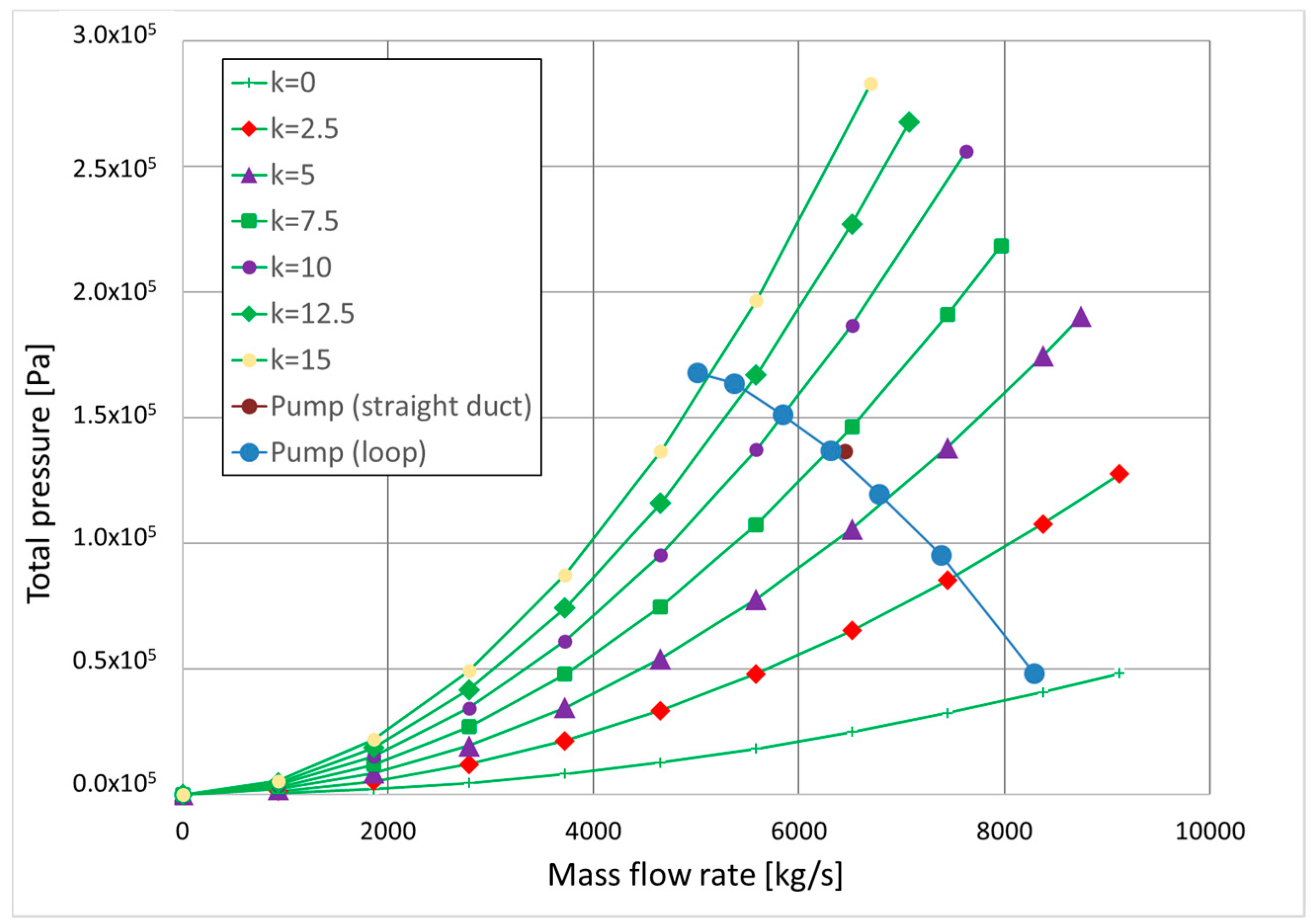
Figure 15 shows the characteristic curve of the pump and it correctly has the typical shape of the characteristic curve of an axial pump. The green curves represent the characteristic curves of the loop, as a function of the pressure jump coefficient values, analytically computed as in the following Equaiton (3), considering the pressure loss due to the length of the loop (1st term in the square brackets), due to the change of flow directions (2nd term in the square brackets, regarding essentially the curves) and due to the insertion of a porous jump BC (3rd term in the square brackets) with a specific coefficient Kpj:
with:
- f = Darcy friction factor
- L/D = geometrical loop sizes
- Kcurv = concentrated pressure losses coefficient of the curves
- Kpj = concentrated pressure losses coefficient of porous jump (pressure jump coefficient).
The reliability of the simulations is confirmed by the partial, and in some cases total, coincidence of the pump operating point and the characteristic curve of the loop for the same values of the pressure jump coefficient. For example, the pump operating point at Kpj = 7.5, perfectly matches the loop characteristic curves computed according to the Equation (3) with Kpj = 7.5.
Finally, the dark red point represents the operating conditions of the pump in a straight duct, described in the previous sections, and its proximity to the pump characteristic curve confirms the validity of the boundary conditions used.
The Archimedean pump presented meets the specifications. While some mechanical concerns have to be addressed (e.g., the mechanical connection of the screw to the hub, the self-centering of the pump’s beam inside the duct), this solution could represent a viable solution as Primary Pump for ALFRED.
3.3. Theoretical and CFD Simulation of the Blade Pump
Conventional axial pump could be a possible solution as the primary pump of ALFRED nuclear reactor, but a semi-axial solutions, could be a more interesting alternative in terms of maximum dimension, in particular regarding the pump shaft length, which involves a less height of the vessel. Screw pump require a long shaft, as reported in the previous section, instead a blade pump allows a smaller area in which are located the blade.
Furthermore, the blade design must be the simplest as possible, with no swirled blade and uniform curvature in the middle plane.
In order to explore the performance and viability of a traditional solution, a conventional blade pump is analyzed as Primary Pump evolving liquid lead. As with the previous geometries, the goals is to obtain the required performance, in terms of mass flow rate and pressure head of the pump, with a compact design of the component, but with a particular attention to the safety requirements. While the two previous pumps were ‘push’ type pumps (suction side at the top, discharge side at the bottom), the blade pump is a ‘pull’ type of pump (suction side at the bottom, discharge side at the top).
The general geometry is designed in accordance with the guidelines for the design of the impeller of conventional semi-axial pumps as outlined in [20], while the geometry of the beam/hub is replaced with a particular profile of the beam, that follows the shroud curvature calculated as proposed in [20], but with an expansion of the meridian cross section, obtained with an enlargement of the pump’s eye diameter (Figure 16). Moreover, an unconventional design for the blades has been developed: while the conventional profile for the blade on a plane normal to the pump’s axis has an angle β1blade ≠ 0 to limit as much as possible the incidence between the relative velocity and the blade leading edge profile, in this specific case the blade angle β1blade is selected equal to zero, with the goal to minimize the pressure losses across the impeller in NC and in locked rotor conditions.
Figure 16 shows the conventional semi-axial impeller scheme [20] and the redesigned impeller developed. It is visible:
- The largest section at the inlet (A-A’ arc of Figure 16a) vs. segment A-A’ of Figure 16b and the outlet (B-B’ segment of Figure 16a) vs. segment B-B’ of Figure 16b section: this reduces the velocity of the flow, the consequent corrosion phenomena and structural load that are due to the high specific weight of the molten lead
- The straight trailing and leading edge: the high inertia of the molten lead flow makes negligible the smallest scale geometry details (like high curvature elements or small fillet) regarding flow deviations.
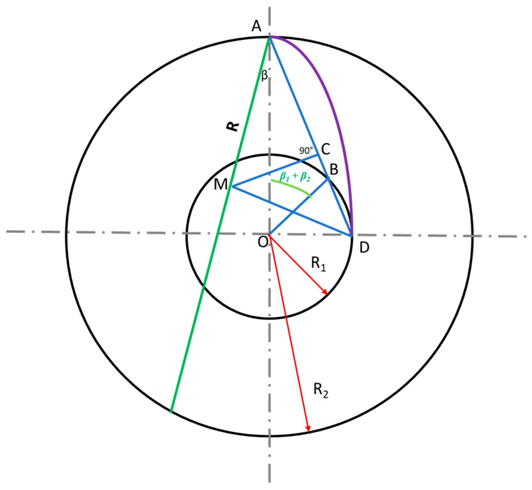
The blade design has been performed by the simple graphical geometric methodology proposed in [21] (Figure 17), that is:
- To construct vane profile
- To draw a single radius circular arc using the calculated angle β1, β2 and radii R1, R2.
Within this method first line is drawn which makes an angle β2 to as shown in Figure 17. Then an angle of β1 + β2 is drawn at O with the radius and a line is drawn from A to the point B, the intersection point on radius R1 and is extended up to D. Then a perpendicular line is drawn in the middle of which intersects at M. will be the radius of arc and arc AD is the vane profile.
The blade exit angle β2blade has been calculated equal to 24 degrees, by the following equation:
where the definition of each symbol can be found in [20].
Different configurations for simulations, with different number of blades, different dimension and shape of the hub and of the inlet, are visible in Figure 18.
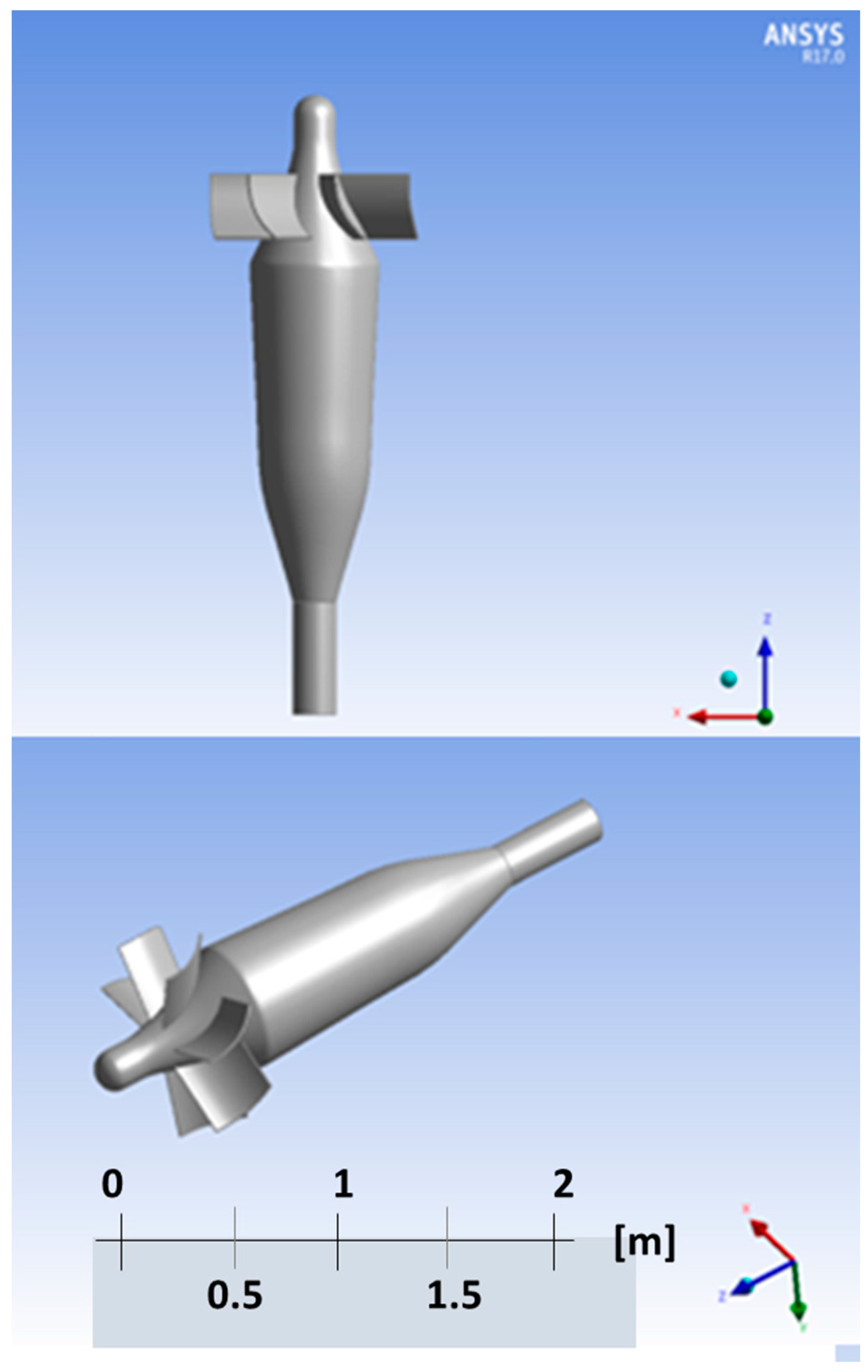
The optimal configuration of this pump is that shown in Figure 18c and Figure 19: this pump reaches a prevalence of 1.9 bar and can elaborate the required mass flow rate with an efficiency of about 85%, as required by the design constraints.
Furthermore, thanks to their low wetted surface (with respect to the screw pump) and to the choice of the blade angle β1blade equal to zero, the pressure loss at pump off is very low, in the order of 10−3 bar.
The resulting design is an innovative semi-axial pump featuring a geometry specifically adapted for the evolving fluid and delivering increased performances with respect to the traditional axial pump, while increasing the required safety characteristics of the traditional axial pump.
Then the pump was placed inside a loop featuring a T-junction pipe envisioned to simulate the connection between the duct of the pump and the steam generator. The placement of the pump inside the loop with the steam generator simulated via a porous jump represents a realistic approximation of the configuration, affordable from the simulation (computational) point of view, since the porous jump was placed on the same location of the inner grid of the steam generator, which works as a simple grid and concentrated pressure loss for an isothermal flow and which evolves naturally to the working point taking into account the different operating conditions of the loop and avoiding any dependencies caused by the choice of the numerical BCs.
The pump delivers the required mass flow rate and pressure head, but, as shown in Figure 20 and Figure 21, some side effects require further optimization of the design:
- The flow leaving the rotor (at the pump’s outlet) is swirled and in correspondence of the T-junction results in a very “chaotic” velocity field. Consequently, the flow entering the steam generator is very irregular with potential problems of uneven coverage of the tube bundle, different thermal loads on the tube bundle and intermittent flow
- The pre-rotation imposed by the impeller to the incoming flow may propagate to the flow leaving the core
4. Discussion
The three pumps have been first analyzed in a theoretical way for and consequently via 3D, detailed spatial simulations to obtain realistic performance data taking into account the peculiar geometry of each pump, as well as the boundary layers and turbulence effects of the flow, which are typically tri-dimensional. The same constraints have been used for the three pumps (liquid lead as working fluid, geometrical dimensions, pressure head generated, mass flow rate evolved, maximum lead velocity less than 15 m/s, no erosion and stagnation effects). Exploiting the peculiar features of each pump, the stated objectives have been met; therefore the three pumps are suitable for their use as Primary Circulation Pump. However, a number of shortcomings (different for each pump) have emerged, namely:
- Jet Pump
- ○
- The liquid lead velocity at the driver’s tip is beyond the current technology for sustained operations
- ○
- The pressure required for the driver is beyond the current technology for sustained operations
- Archimedean (screw) Pump
- ○
- The mechanical connection of the screw to the hub requires welding, a processing technique presenting a number of challenges when applied in flowing liquid lead
- ○
- The self-centering of the pump’s beam inside the duct presents significant mechanical challenges
- Blade Pump
- ○
- The flow downstream the pump presents a significant swirling component
- ○
- The pre-rotation of the flow upstream of the rotor may impact on the flow field exiting from the core
The blade pump shows the best performance in terms of pressure head generated and pressure drop at pump off: the first allows the proper operations of the primary system, as required by the Ansaldo Nucleare design constraint, the last is a key feature to allow the establishment of NC of the flow during the accidental conditions which include the pump stop.
However, further improvements of the geometrical configuration are necessary, not by the point of view of the blade or shroud components, which comply the required parameter/performance, but in terms of the resulting flow going towards the Steam Generator: the high swirling component could be reduced with a constriction of the outlet section after the blade, or with statoric component keyed on the pump external pipe. The first solution is the most likely to be prosecuted, while the second is difficult to implement, due to the requirements of the extractability of the pumps during the operation of inspection or substitutions, which would be infeasible if the section of the pipe is obstructed by other components.
5. Materials and Methods
5.1. General Considerations and CFD Analysis of Selected Pumps
As already anticipated, at present, there are two possible plant configurations under: the first one with four pumps and the second with eight pumps. In this work, the first option will be evaluated and hence, based on design calculation developed by Ansaldo Nucleare S.p.A. [6], each pump has to generate:
- Mass flow rate = 6450 kg/s = 2200 m3/h
- Pump differential pressure = 1.5 bar ( head = 1.48 m).
These first design constraints are already a very important indication to understand what kind of pump we need. Indeed, in literature [22,23] several guidelines for selecting the pump as a function of the differential pressure (proportional to head) and mass flow rate are available.
According to the chart in Figure 22, the best pumping device to achieve the boundary conditions is an axial pump.
There are other design constraints dictated by the peculiar roles of this pumping device:
- Generate the design mass flow rate and differential pressure keeping the minimum velocity inside the pump to limit erosion phenomena
- Minimize the flow resistance, when the pumps is non-rotating, to reduce the obstacles for the onset of NC of the fluid in accidental situation
- Have a self-centering effect inside th pump duct to overcome the absence of a bearing under the pump.
Therefore, due to these peculiar design constraints, most of pumping devices commonly used in industrial application cannot be used; among the others, a particular kind of axial screw pump will be envisioned in this paper with a completely new approach to the analysis and design.
5.2. A Short Introduction to the CFD Model Developed and Multiple Reference Frame CFD Model Approach for Rotating Frame
In the case of Jet pumps, a standard pressure based solver has been used, but using rotating geometry (screw and semi axial pump), requires the simulation of the relative flow between the blade and the fluid; in this case, has been adopted the Multiple Reference Frame (MRF) model, and, as will be show in the next, a sliding mesh approach has been used for a further verify calculation.
The MRF [11] model is, perhaps, the simplest of the two approaches for multiple zones: it is a steady-state approximation in which individual cell zones move at different rotational and/or translational speeds. The flow in each moving cell zone is obtained using the moving reference frame equations. If the zone is stationary, the stationary equations are used. At the interfaces between cell zones, a local reference frame transformation is performed to enable flow variables in one zone to be used to calculate fluxes at the boundary of the adjacent zone.
It should be noted that the MRF approach does not account for the relative motion of a moving zone with respect to adjacent zones (which may be moving or stationary); the grid remains fixed for the computation. This is analogous to freezing the motion of the moving part in a specific position and observing the instantaneous flow field with the rotor in that position. Hence, the MRF is often referred to as the “frozen rotor approach”.
While the MRF approach is clearly an approximation, it can provide a reasonable model of the flow for many applications. For example, the MRF model can be used for turbo-machinery applications in which rotor-stator interaction is relatively weak, and the flow is relatively not complicated at the interface between the moving and stationary zones. In mixing tanks, for example, since the impeller-baffle interactions are relatively weak, large-scale transient effects are not present: then MRF model can be used.
Another potential use of the MRF model is to compute a flow field to be used as an initial condition for a transient sliding mesh calculation. This eliminates the need for a start-up calculation. The MRF model should not be used, however, if it is necessary to actually simulate the transients occurring in strong rotor-stator interactions: in such cases the sliding mesh model alone should be used.
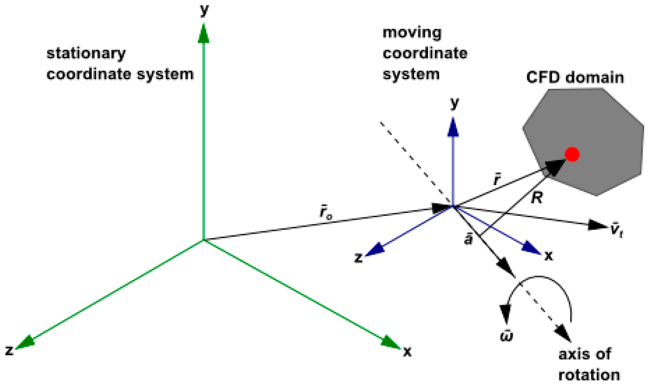
Consider a coordinate system which is rotating steadily with angular velocity relative to a stationary (inertial) reference frame, as illustrated in Figure 23. The origin of the rotating system is located by a position vector rs.
The axis of rotation is defined by a unit direction vector such that:
The computational domain for the CFD problem is defined with respect to the rotating frame such that an arbitrary point in the CFD domain is located by a position vector from the origin of the rotating frame.
The fluid velocities can be transformed from the stationary frame to the rotating frame using the following relation:
where:
In the above, is the relative velocity (the velocity viewed from the rotating frame), is the absolute velocity (the velocity viewed from the stationary frame), is the velocity of the moving frame relative to the inertial reference frame, is the angular velocity and is the translational frame velocity. It should be noted that both and can be functions of time.
When the equations of motion are solved in the rotating reference frame, the acceleration of the fluid is augmented by additional terms that appear in the momentum equations. Moreover, the equations can be formulated in two different ways:
- Expressing the momentum equations using the relative velocities as dependent variables (known as the relative velocity formulation)
- Expressing the momentum equations using the absolute velocities as dependent variables in the momentum equations (known as the absolute velocity formulation).
For the absolute velocity formulation, that is used in the present work, the equations of fluid flow for a steadily rotating frame can be written as follows:
- Conservation of mass:
- Conservation of momentum:
- Conservation of energy:
In this formulation, the Coriolis and centripetal accelerations can be collapsed into a single term .
6. Conclusions
The detailed modelling of 3 pumps, namely the Jet pump, the Archimedean (screw) pump and the Blade pump, has been performed with the objective of design optimization of each concept as PCP for ALFRED.
While the design of the Jet pump looks like beyond the current technological feasibility, once the mechanical challenges of the Archimedean (screw) pump and the fluid-dynamic issues of the Blade pump will be addressed, they could represent viable solutions as Main Primary Pump for ALFRED.
Particularly, the blade pump shows the best performance in terms of pressure head generated and pressure drop at pump off in locked rotor conditions. However further optimizations (mainly for what the geometrical configuration is concerned) are still necessary.
Acknowledgments
Work supported in part by project OCAPIE, funded by Compagnia di San Paolo (Turin, Italy) under contract #9535. The CFD calculations developed in this work have been run on the HPC OCAPIE cluster.
Author Contributions
A.A., W.B. and F.M. conceived the conceptual design of the pumps; W.B. and F.M. performed the calculations; W.B., G.L. and F.M. analyzed the data; W.B., G.L. and F.M. wrote the paper; A.A., G.L. and P.S. supervised the whole research and revised the paper.
Conflicts of Interest
The authors declare no conflict of interest.
References
- Castelliti, D.; Lomonaco, G. A preliminary stability analysis of MYRRHA primary heat exchanger two-phase tube bundle. Nucl. Eng. Des. 2016, 305, 179–190. [Google Scholar] [CrossRef]
- Borreani, W.; Bruzzone, M.; Chersola, D.; Firpo, G.; Lomonaco, G.; Palmero, M.; Panza, F.; Ripani, M.; Saracco, P.; Viberti, C.M. Preliminary thermal-fluid-dynamic assessment of an ADS irradiation facility for fast and slow neutrons. Int. J. Heat Technol. 2017, 35, S186–S190. [Google Scholar] [CrossRef]
- Panza, F.; Firpo, G.; Lomonaco, G.; Osipenko, M.; Ricco, G.; Ripani, M.; Saracco, P.; Viberti, C.M. New infrastructure for studies of transmutation and fast systems concepts. EPJ Web Conf. 2017, 153, 05003. [Google Scholar] [CrossRef]
- Lomonaco, G.; Borreani, W.; Bruzzone, M.; Chersola, D.; Firpo, G.; Palmero, M.; Panza, F.; Ripani, M.; Saracco, P.; Viberti, C.M. Initial thermal-hydraulic assessment by OpenFOAM and FLUENT of a subcritical irradiation facility. Therm. Sci. Eng. Prog. 2017. under review. [Google Scholar]
- International Atomic Energy Agency (IAEA). Nuclear Power Reactors in the World; Reference Series No. 2; IAEA: Vienna, Austria, 2013. [Google Scholar]
- Alemberti, A.; Lomonaco, G.; Borreani, W.; Magugliani, F. Theoretical and numerical investigation of three designs for a primary circulation pump evolving liquid lead for GEN-IV reactors. In Proceedings of the IV ISTC NIKIET “Innovative Designs and Technologies of Nuclear Power”, Moscow, Russia, 27–30 September 2016. [Google Scholar]
- Cerullo, N.; Lomonaco, G. Generation IV reactor designs, operation and fuel cycle. In Nuclear Fuel Cycle Science and Engineering; Crossland, I., Ed.; Woodhead Publishing: Cambridge, UK, 2012; pp. 333–395. [Google Scholar] [CrossRef]
- Nuclear Energy Agency. Handbook on Lead-Bismuth Eutectic Alloy and Lead Properties, Materials Compatibility, Thermal-Hydraulics and Technologies; Nuclear Energy Agency: Boulogne-Billancourt, France, 2015; Available online: https://www.oecd-nea.org/science/pubs/2015/7268-lead-bismuth-2015.pdf (accessed on 30 September 2017).
- Menter, F.R. Zonal two equation k-ω Turbulence models for aerodynamic flows. In Proceedings of the 23rd Fluid Dynamics, Plasmadynamics, and Lasers Conference, Orlando, FL, USA, 6–9 July 1993. AIAA Paper 93-2906. [Google Scholar]
- Tennekes, H.; Lumley, J.L. A First Course in Turbulence, 1st ed.; MIT Press: Cambridge, MA, USA, 1972; ISBN 9780262200196. [Google Scholar]
- Hirsch, C. Numerical Computation of Internal and External Flows: The Fundamentals of Computational Fluid Dynamics, 2nd ed.; Butterworth-Heinemann: Oxford, UK, 2007; ISBN 9780750665940. [Google Scholar]
- Borreani, W. Thermo-Hydraulic Analysis by Different CFD Codes of Some Components of the Primary System of Gen-IV Lead-Cooled Demonstrator ALFRED. Ph.D. Thesis, University of Genova, Genoa, Italy, 2017. [Google Scholar]
- ANSYS. Available online: http://www.ansys.com/Products/Fluids/ (accessed on 30 September 2017).
- The RELAP5-3D Code Development Team. RELAP5-3D© Code Manual Volume I: Code Structure, System Models and Solution Methods; INEEL-EXT-98-00834, Revision 2.3; Idaho National Laboratory: Idaho Falls, ID, USA, 2005.
- Mangialardo, A.; Borreani, W.; Lomonaco, G.; Magugliani, F. Numerical investigation on a jet pump evolving liquid lead for GEN-IV reactors. Nucl. Eng. Des. 2014, 280, 608–618. [Google Scholar] [CrossRef]
- Cunningham, R.G. Jet pump theory. In Pump Handbook, 3rd ed.; Karassik, I.J., Messina, J.P., Cooper, P., Heald, C.C., Eds.; McGraw-Hill: New York, NY, USA, 2007. [Google Scholar]
- El-Sawaf, I.A.; Halawa, M.A.; Younes, M.A.; Teaima, I.R. Study of the different parameters that influence on the performance of water jet pump. In Proceedings of the 15th International Water Technology Conference (IWTC 15), Alexandria, Egypt, 31 March–2 April 2011. [Google Scholar]
- Lizzoli, M.; Borreani, W.; Devia, F.; Lomonaco, G.; Tarantino, M. Preliminary CFD assessment of an experimental test facility operating with heavy liquid metals. Sci. Technol. Nucl. Install. 2017, 2017, 1949673. [Google Scholar] [CrossRef]
- Ferrini, M.; Borreani, W.; Lomonaco, G.; Magugliani, F. Design by theoretical and CFD analyses of a multi-blade screw pump evolving liquid lead for a Generation IV LFR. Nucl. Eng. Des. 2016, 297, 276–290. [Google Scholar] [CrossRef]
- Gülich, J.F. Centrifugal Pumps, 3rd ed.; Springer: Berlin, Germany, 2014. [Google Scholar]
- Sahu, G.K. Pumps; New Age International Ltd.: New Delhi, India, 2005; ISBN 81-224-1224-6. [Google Scholar]
- Srinivasan, K.M. Rotodynamic Pumps (Centrifugal and Axial); New Age International: New Delhi, India, 2008. [Google Scholar]
- Nesbitt, B. Handbook of Pumps and Pumping; Elsevier: Amsterdam, The Netherlands, 2006; ISBN 9781856174763. [Google Scholar]
Figure 1.
Conceptual configuration of ALFRED.

Figure 2.
(a) push-type configuration; (b) pull-type pump configuration.
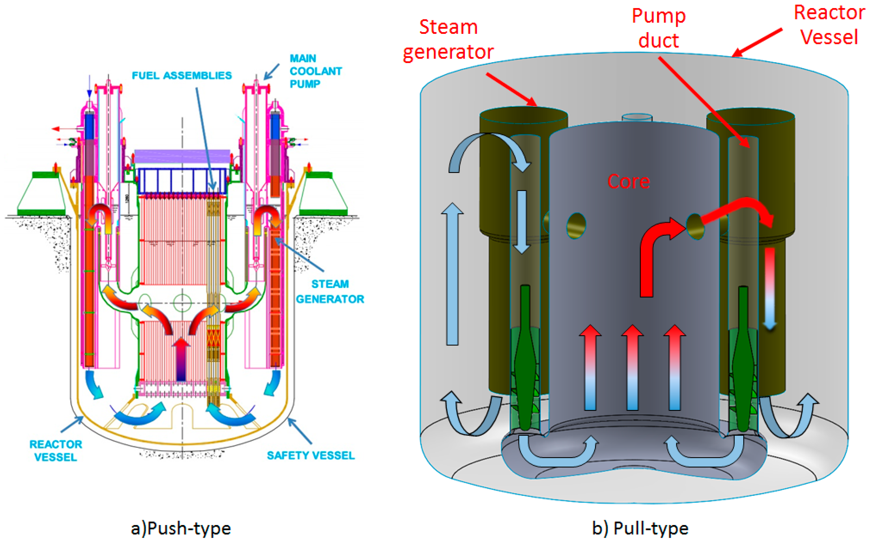
Figure 3.
Comparison between the conceptual (Left) and the jet pump-based configuration of ALFRED (Right).
Figure 3.
Comparison between the conceptual (Left) and the jet pump-based configuration of ALFRED (Right).
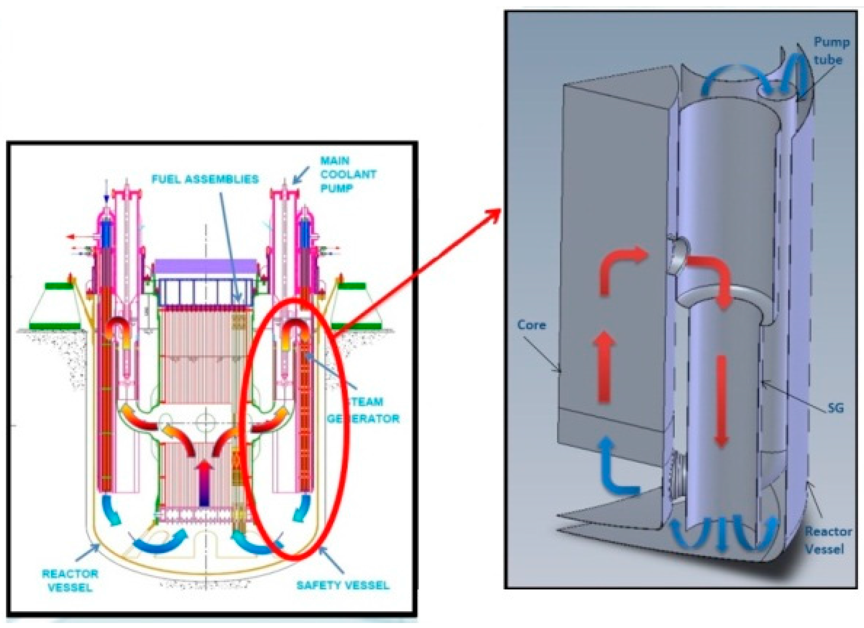
Figure 4.
Lead jet pump: (a) geometry model; (b) flow patterns.
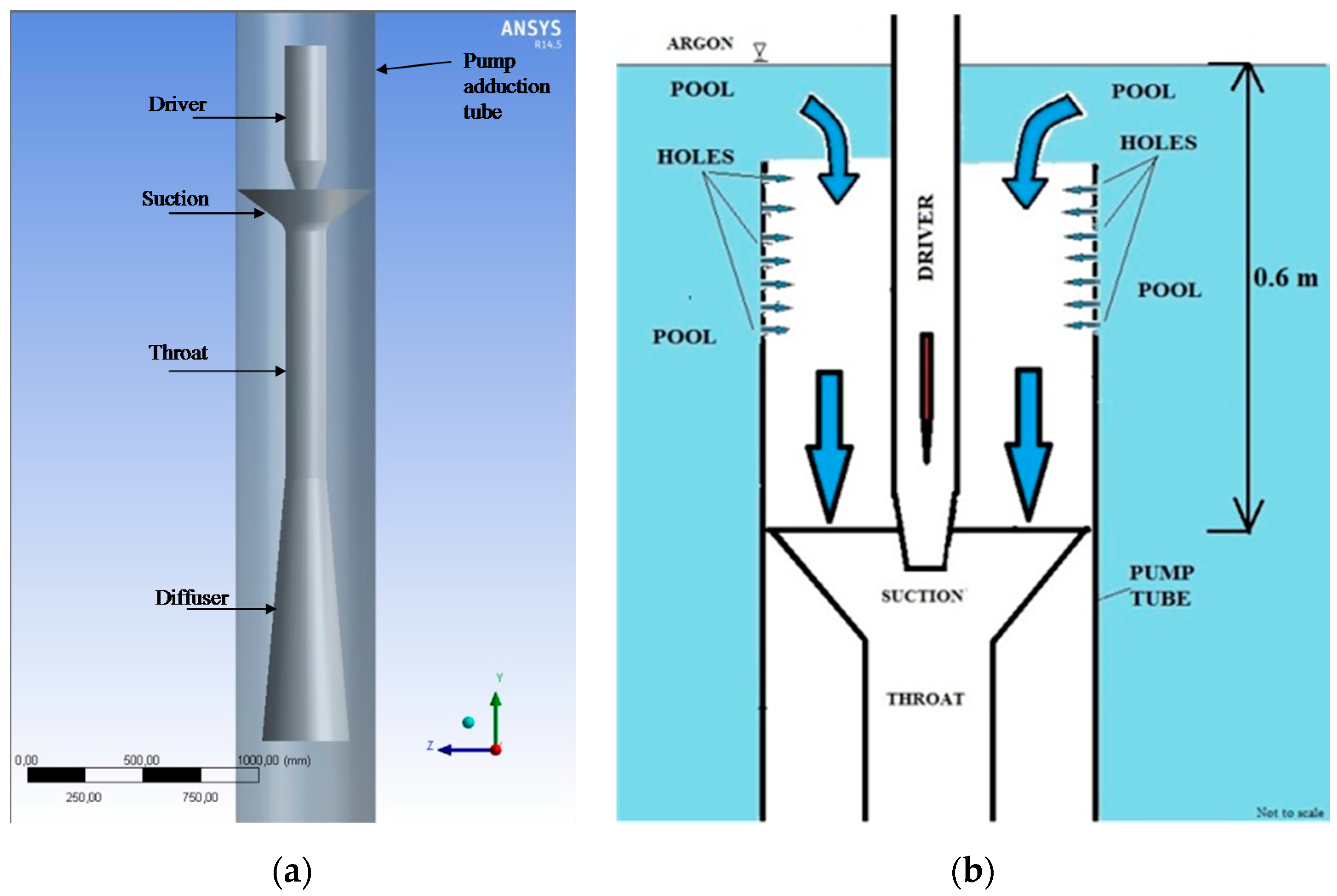
Figure 5.
Velocity vectors (magnitude).

Figure 6.
Contours of nozzle velocity (magnitude).

Figure 7.
Velocity triangle at the in and out sections.

Figure 8.
Screw pump with increasing pitch and velocity triangles.
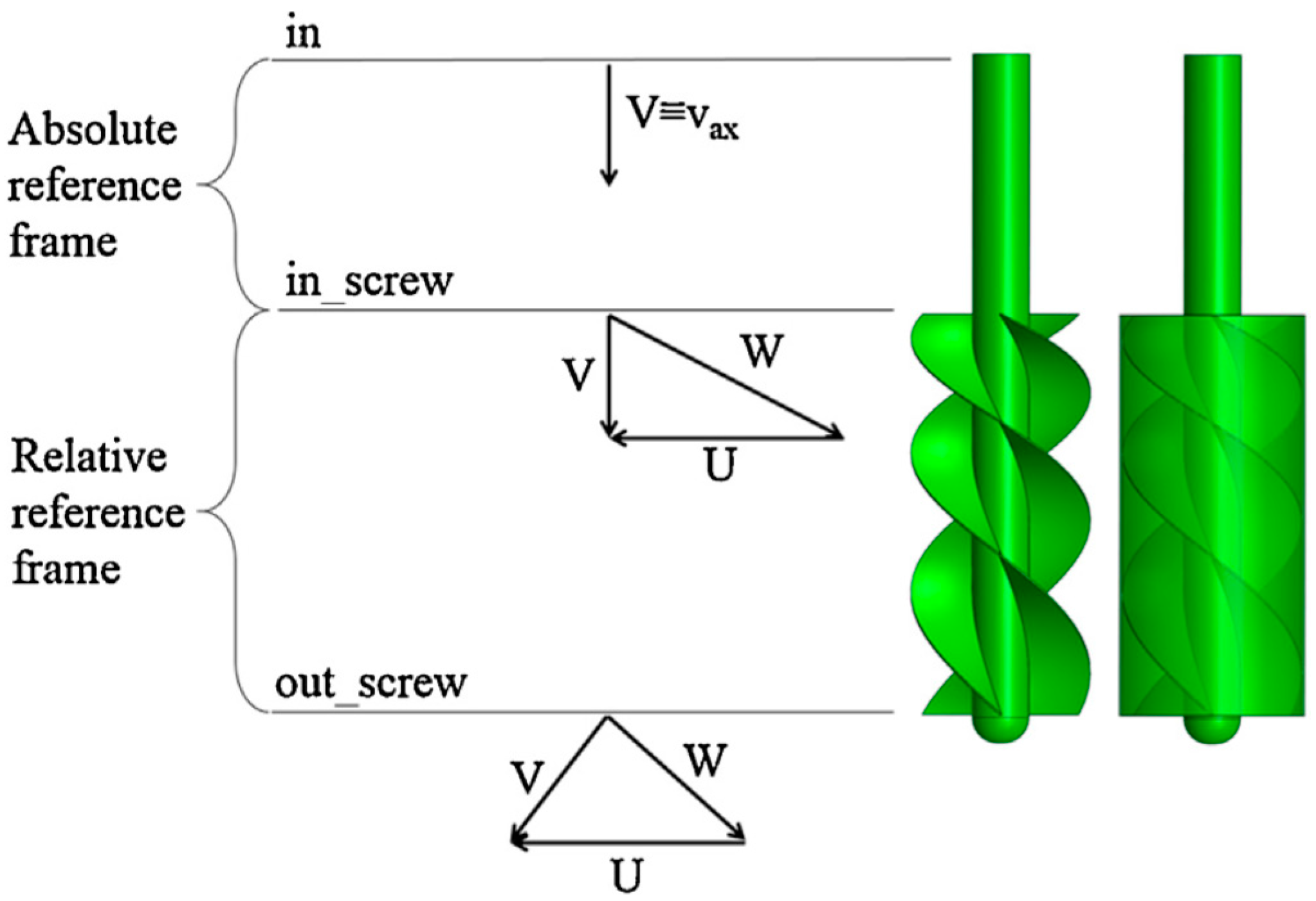
Figure 9.
Screw pump with variable hub diameter and velocity triangles.
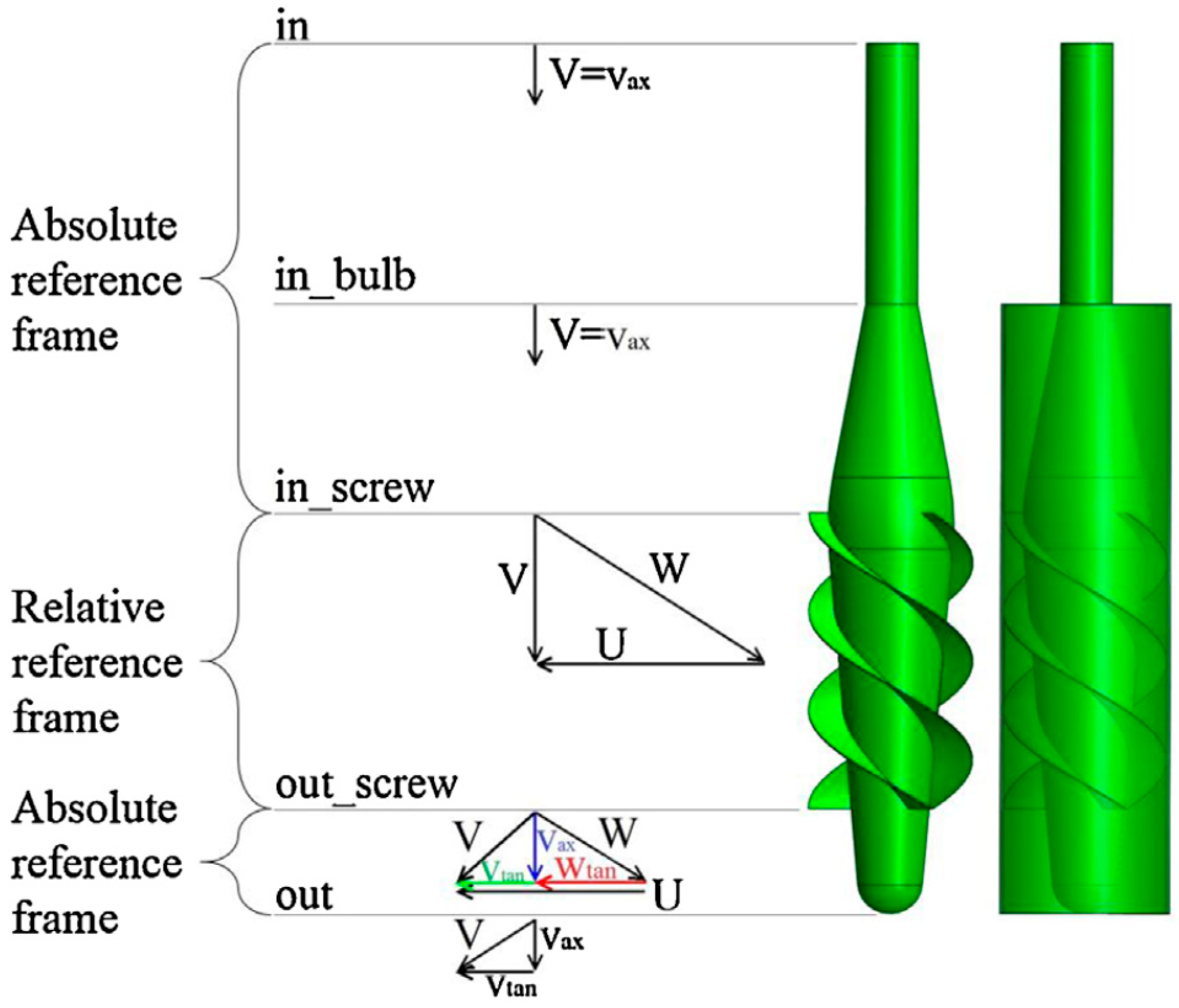
Figure 10.
Optimal design of the Archimedean pump: velocity streamlines (Left), velocity contours (Middle) and static pressure contours (Right) on a longitudinal plane.
Figure 10.
Optimal design of the Archimedean pump: velocity streamlines (Left), velocity contours (Middle) and static pressure contours (Right) on a longitudinal plane.
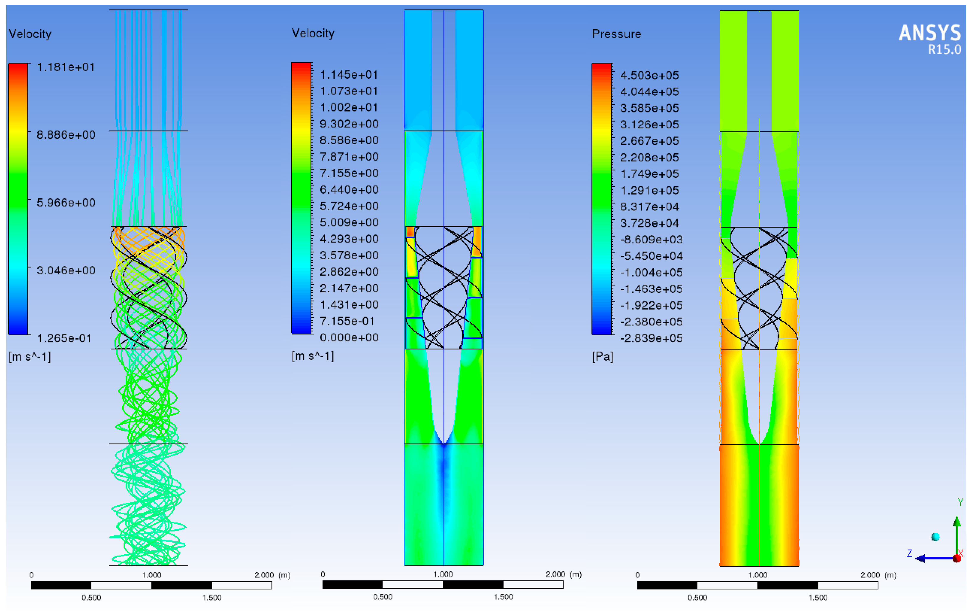
Figure 11.
Optimal design of the Archimedean pump: differential total pressure as a function of the mass flow rate.
Figure 11.
Optimal design of the Archimedean pump: differential total pressure as a function of the mass flow rate.
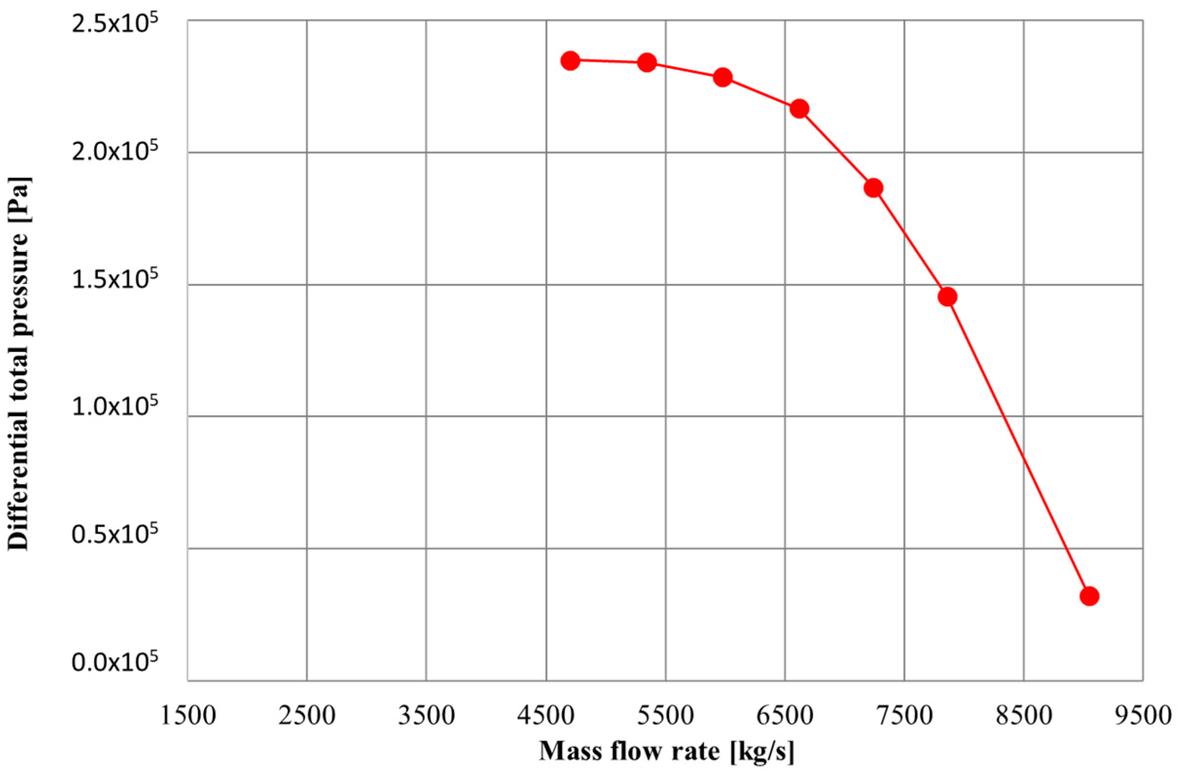
Figure 12.
NC conditions: streamlines, velocity and pressure.

Figure 13.
NC conditions: zoom on the frusto-conical diverging part.

Figure 14.
Loop simulation: velocity contours (Left), static pressure contours (Middle) and total pressure contours (Right) on a longitudinal plane.
Figure 14.
Loop simulation: velocity contours (Left), static pressure contours (Middle) and total pressure contours (Right) on a longitudinal plane.
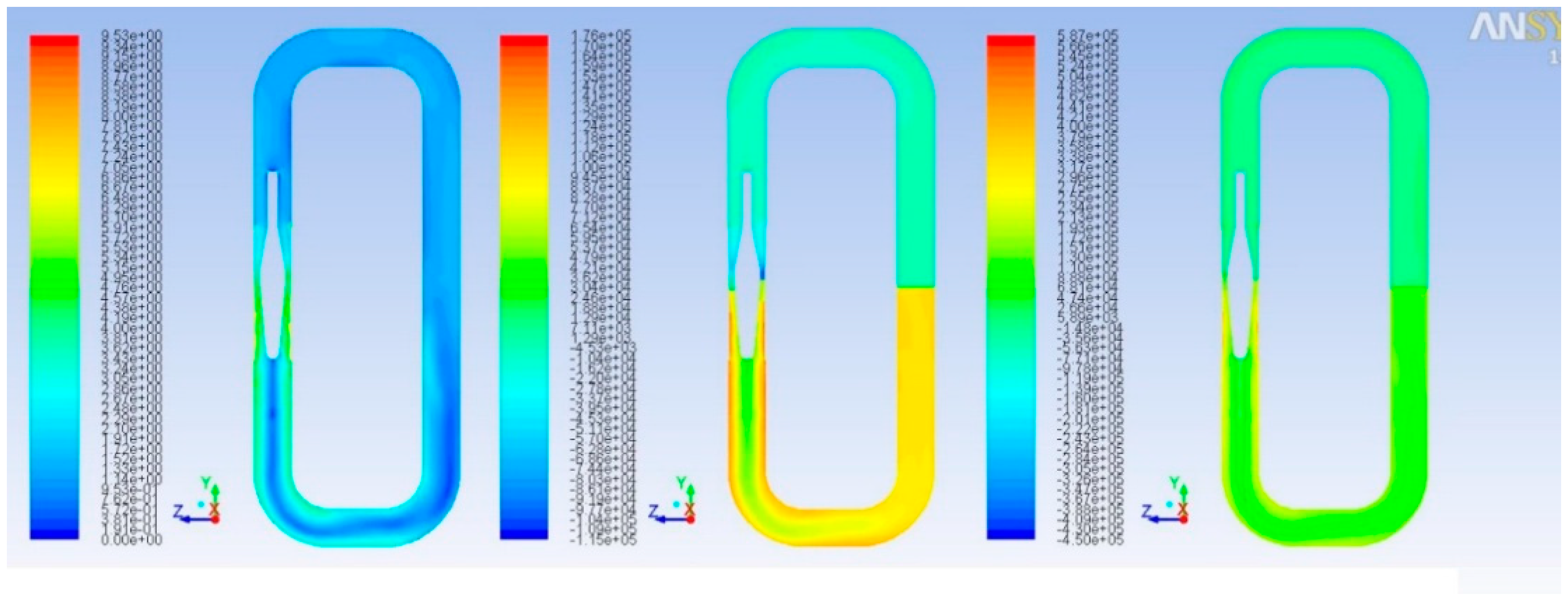
Figure 15.
Characteristic curve of the pump, of the loop and operating point of the pump into the straight duct.
Figure 15.
Characteristic curve of the pump, of the loop and operating point of the pump into the straight duct.

Figure 16.
(a) Semi-axial impeller dimension [20]; (b) modified semi/axial impeller for lead pump developed.
Figure 16.
(a) Semi-axial impeller dimension [20]; (b) modified semi/axial impeller for lead pump developed.
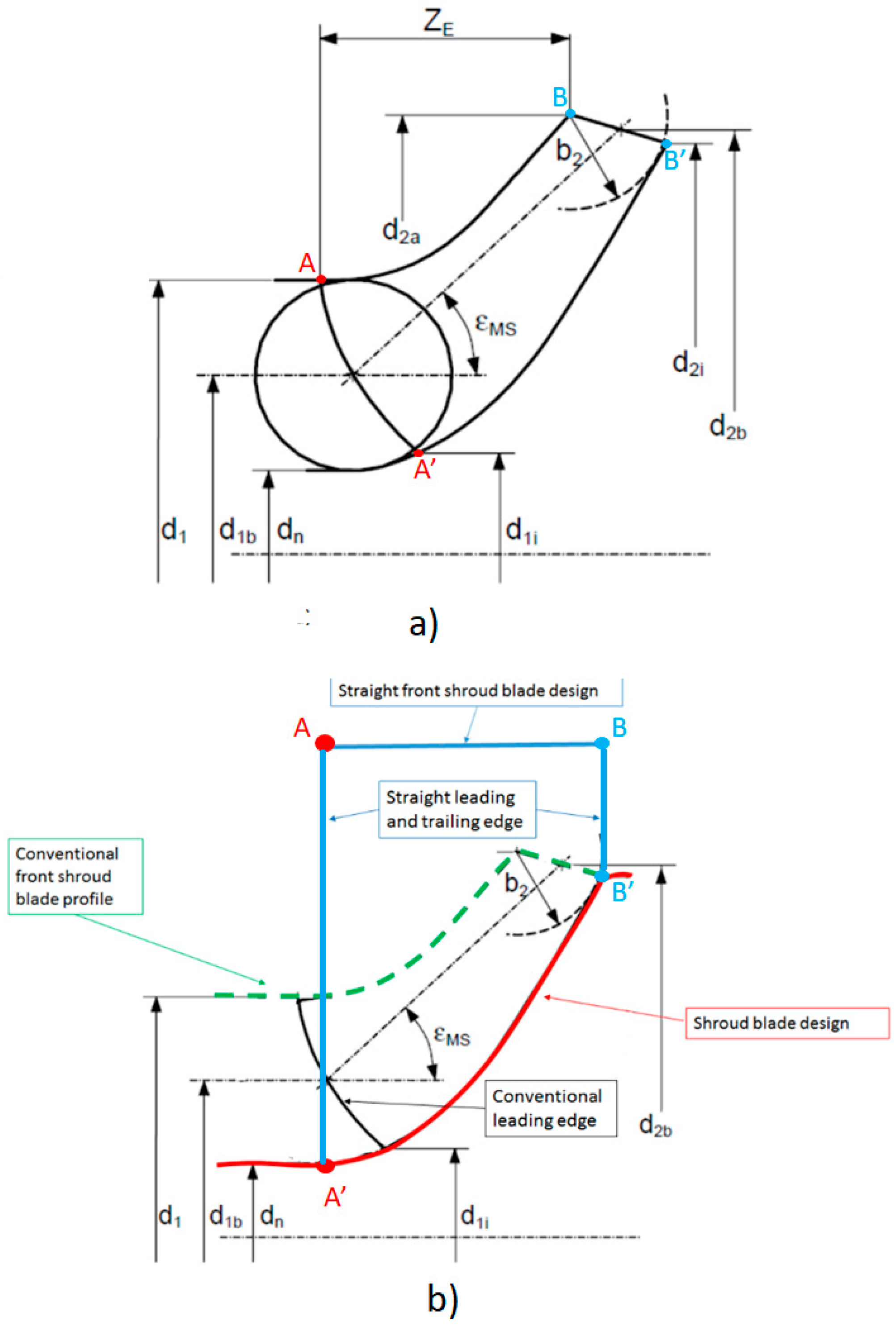
Figure 17.
Simple geometric method of constructing vane profile.

Figure 18.
Different geometrical pump configurations: (a,b) short hemispheric hub with 5 blade and (c) long hub working like a diffuser.
Figure 18.
Different geometrical pump configurations: (a,b) short hemispheric hub with 5 blade and (c) long hub working like a diffuser.
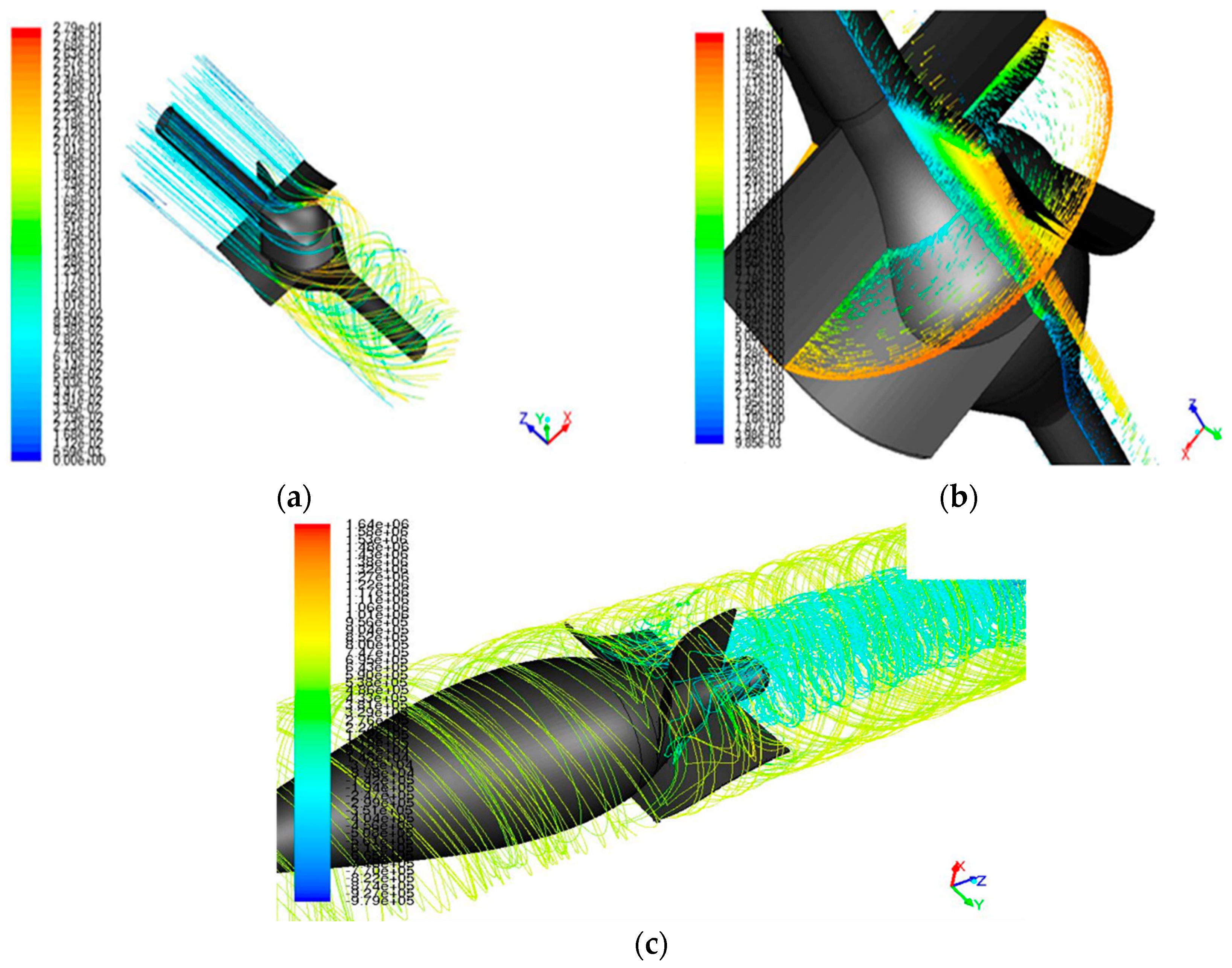
Figure 19.
Blade pump.

Figure 20.
Pathlines inside the virtual loop (the high flow swirl at the SG inlet is visible).

Figure 21.
Velocity contours plotted on different plane inside the fluid domain.

Figure 22.
Pump selection as per head and mass flow rate [23].
Figure 22.
Pump selection as per head and mass flow rate [23].
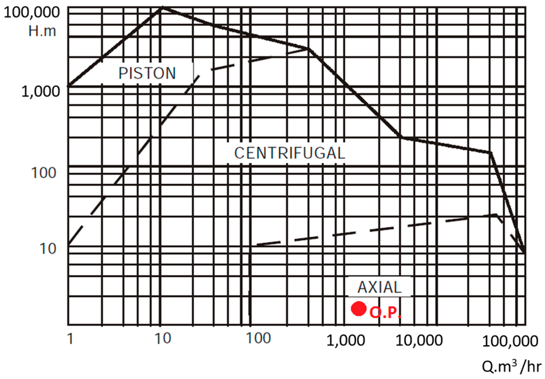
Figure 23.
Stationary and Rotating Reference Frames.


Table 1.
Thermo-physical proprieties of water, sodium and lead: above the name of the coolant were reported the normal operating conditions in the nuclear coolant system use [8].
Table 1.
Thermo-physical proprieties of water, sodium and lead: above the name of the coolant were reported the normal operating conditions in the nuclear coolant system use [8].
| Coolant | H2O (155 bar, 573 K) | Na (1 bar, 673 K) | Pb (1 bar, 673 K) | |
|---|---|---|---|---|
| Proprieties | ||||
| Density (kg/m3) | 727 | 856 | 10563 | |
| Tmelting (K) | - | 371 | 601 | |
| Tboiling (K) | 618 | 1156 | 2023 | |
| Heat capacity (J/(m3·K)) | 3.9 × 10⁶ | 1.1 × 10⁶ | 1.5 × 10⁶ | |
| Dynamic viscosity (Pa·s) | 0.09 × 10⁻³ | 0.28 × 10⁻³ | 2.23 × 10⁻³ | |
| Thermal Conductivity (W/mK) | 0.6 | 72 | 17 | |
| Vapor pressure (Pa) | 8.6 × 10⁶ | 52 | 2.8 × 10⁻⁵ | |
Table 2.
ALFRED key parameters [6].
Table 2.
ALFRED key parameters [6].
| Parameter | Value |
|---|---|
| Power | 300 MWth |
| Primary coolant | Lead |
| Primary system | Pool type, compact |
| Primary side lead temperature | 400 ÷ 480 °C |
| Primary coolant circulation (at power) | Forced (mechanical pumps) |
| Primary pump | 8, mechanical, removable, located in hot leg inside the inner vessel |
| Steam generator | 8, once-through, removable, integrated in the main vessel |
| Secondary cycle | Water superheated steam at 180 bar, 335 ÷ 450 °C |
| Decay heat removal | 2, independent, redundant and diverse DHR systems |
| Overall efficiency | 40% (or higher) |
| Internals | All internals removable |
Table 3.
Liquid lead properties equations [8], T is the Temperature expressed in K.
Table 3.
Liquid lead properties equations [8], T is the Temperature expressed in K.
| Density (kg/m3) | ρ = 11441 − 1.2795 × T |
| Dynamic viscosity (Pa·s) | µ = 4.55 × 10⁻⁴ × e(1069/T) |
Table 4.
Comparison conditions for reference case and optimal performance.
| Case | (kg/s) | (kg/s) | M | N | Ptotsuction (bar) | Ptotdriver (bar) |
|---|---|---|---|---|---|---|
| Reference case | 2202 | 1250 | 1.76 | 0.229 | 1.63 | 26.3 |
| Optimal case | 2010 | 1310 | 1.53 | 0.28 | 1.63 | 23 |
© 2017 by the authors. Licensee MDPI, Basel, Switzerland. This article is an open access article distributed under the terms and conditions of the Creative Commons Attribution (CC BY) license (http://creativecommons.org/licenses/by/4.0/).
Share and Cite
MDPI and ACS Style
Borreani, W.; Alemberti, A.; Lomonaco, G.; Magugliani, F.; Saracco, P. Design and Selection of Innovative Primary Circulation Pumps for GEN-IV Lead Fast Reactors. Energies 2017, 10, 2079. https://doi.org/10.3390/en10122079
AMA Style
Borreani W, Alemberti A, Lomonaco G, Magugliani F, Saracco P. Design and Selection of Innovative Primary Circulation Pumps for GEN-IV Lead Fast Reactors. Energies. 2017; 10(12):2079. https://doi.org/10.3390/en10122079
Chicago/Turabian StyleBorreani, Walter, Alessandro Alemberti, Guglielmo Lomonaco, Fabrizio Magugliani, and Paolo Saracco. 2017. "Design and Selection of Innovative Primary Circulation Pumps for GEN-IV Lead Fast Reactors" Energies 10, no. 12: 2079. https://doi.org/10.3390/en10122079
Note that from the first issue of 2016, this journal uses article numbers instead of page numbers. See further details here.