Floor Heave Mechanism of Gob-Side Entry Retaining with Fully-Mechanized Backfilling Mining

1
State Key Laboratory for Geomechanics and Deep Underground Engineering, School of Mechanics and Civil Engineering, China University of Mining & Technology, Xuzhou 221116, China
2
Department of Mechanical Engineering, Colorado School of Mines, Golden, CO 80401, USA
*
Author to whom correspondence should be addressed.
Energies 2017, 10(12), 2085; https://doi.org/10.3390/en10122085
Submission received: 15 October 2017
/
Revised: 20 November 2017
/
Accepted: 5 December 2017
/
Published: 8 December 2017
(This article belongs to the Collection Bioenergy and Biofuel)
Abstract
:Serious floor heave in gob-side entry retaining (GER) with fully-mechanized gangue backfilling mining affects the transportation and ventilation safety of the mine. A theoretical mechanical model for the floor of gob-backfilled GER was established. The effects of the mechanical properties of floor strata, the granular compaction of backfilling area (BFA), the vertical support of roadside support body (RSB), and the stress concentration of the solid coal on the floor heave of the gob-backfilled GER were studied. The results show that the floor heave increases with the increase of the coal seam buried depth, and decreases with the increase of the floor rock elastic modulus. The development depth of the plastic zone decreases with the increase of the c and φ value of the floor rock, and increases with the increase of the stress concentration factor of the solid coal. The development depth of the plastic zone in the test mine reached 2.68 m. The field test and monitoring results indicate that the comprehensive control scheme of adjusting backfilling pressure, deep grouting reinforcement, shallow opening stress relief slots, and surface pouring can effectively control the floor heave. The roof-floor displacement is reduced by 73.8% compared to that with the original support scheme. The roadway section meets the design and application requirements when the deformation stabilizes, demonstrating the rationality of the mechanical model. The research results overcome the technical bottleneck of floor heave control of fully-mechanized backfilling GER, providing a reliable basis for the design of a floor heave control scheme.
1. Introduction
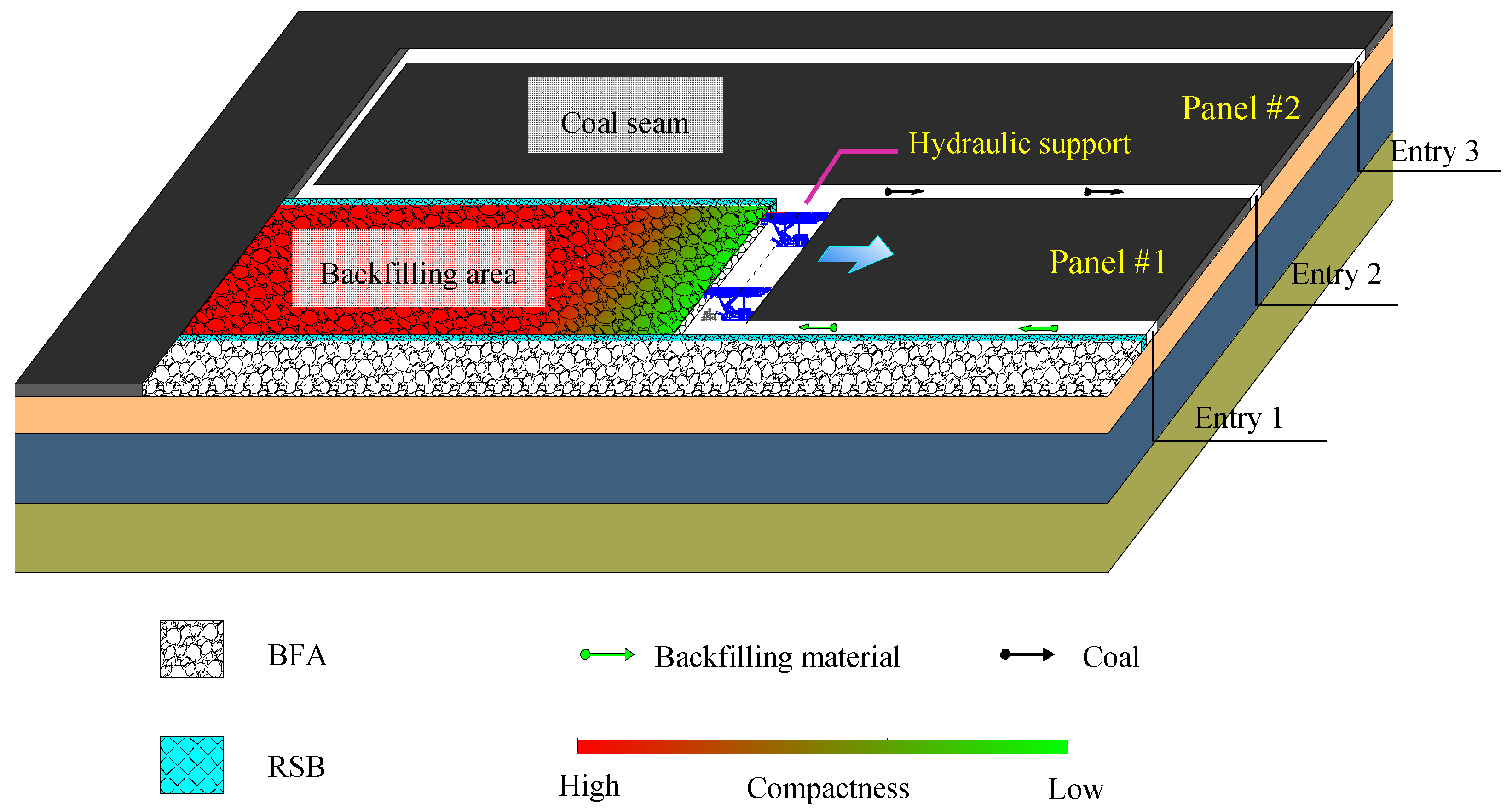
In gob-side entry retaining (GER) of underground coal seam mining, the headgate (entry 2 front of the active panel #1) of the current mining panel (panel #1) is retained by constructing the roadside support body (RSB) and serves as the tailgate (entry 2 behind of the active panel #1) to the subsequent adjacent panel (panel #2) [1,2] (Figure 1). For the gob-backfilled GER technology, a roadside artificial wall was built to maintain the roadway based on the backfilled gangue supporting the roof. This technology has the following advantages: (1) Backfilling mining can consume a large amount of waste gangues piled up on the ground, control the surface subsidence, turn waste into usable materials, and alleviate environmental stress; (2) The compacted gangues in the backfilling area (BFA) can limit the roof deformation, reducing the load during roof weighting and avoiding rock burst accidents of the working face [3,4,5,6,7]; (3) Owing to the support of gangues in the BFA, the support pressure of the RSB is reduced, which is favorable for stabilizing the RSB, thus improving the success rate of entry retaining. Therefore, the GER technology with fully-mechanized backfilling is adaptable to complex geological conditions such as deep roadways, high stress, large mining height, and weak surrounding rock, expanding the application range of GER technology [8,9,10]. However, it is found in the engineering practice of the gob-backfilled GER that the floor heave in the retained entry is larger than that in the GER with roof management using the caving method. In GER with fully-mechanized backfilling, the amount of floor heave accounts for more than 70% of the roof-floor displacement, leading to serious convergence of roadway sections, thus affecting the normal transportation (Figure 2a) and seriously threatening the ventilation safety of the roadway. Moreover, the local roadway floor is seriously damaged, breaking through the floor sandstone aquifer, resulting in a water inrush accident of the roadway floor (Figure 2b), as well as seriously affecting the safety of the roadway and the normal production of the mine.
Under the condition of gob-backfilled mining, the stress and deformation characteristics of the surrounding rocks are radically changed due to the supportive effect of BFA on the roof. At present, the research on backfill mining is more focused on the mechanical properties of filling materials and roof deformation of stope. Sheshpari [11] holds that the gob-backfilled mining method increases the stability of the mined area and decreases land subsidence and rock bursts due to stress pattern changes. Jehring and Bareither [12] analyzed the tailings composition effects on the shear strength behavior of co-mixed mine waste rock and tailings. The study by Huang et al. [13] shows that the fracture of the main roof is mainly controlled by the filling ratio and is non-correlated to the shield supporting pressure.
In recent years, some scholars have studied the deformation mechanism of surrounding rock in GER and floor heave control in dynamic pressure roadways, achieving many positive results. He et al. [14] analyzed the stress distribution characteristics of deep coal roadways, and proposed an integrated method of controlling floor heave by establishing a numerical calculation model. Lin et al. [15] believed that the pressure of floor heave in GER of deep swelling soft rock comes from the transfer of the “compression mold effect” in the backfilling body and solid coal, lateral pressure generated by main roof rotation, compaction of caving gangue in the gob area, deep high stress, and soft rock swelling pressure. Sun et al. [16] obtained the dangerous location of asymmetric floor heave in the slightly-inclined coal seam roadway through physical simulation tests, explaining the formation of floor heave in a slightly-inclined coal seam roadway combined with infrared images, video pictures, and monitoring results of strain. Tang et al. [17] proposed a numerical simulation method based on humidity diffusion, and conducted a numerical simulation of floor heave of swelling rock tunnels under high humidity condition. Time-dependent deformation and the failure process of the tunnel under high humidity conditions were discussed. Li and Weng [18] analyzed the influence of dynamic loading on the fracture process of surrounding rock in deep roadways. Zhang et al. [19] studied the effect of different thicknesses of immediate roof on the deformation and fracture characteristics of roof in gob-side entry, and deduced a formula of rational support resistance of RSB. Gong et al. [20] analyzed the effect of initial compaction of BFA on the deformation of retained entry roof and the stability of RSB by using physical simulation, which demonstrated the decisive effect of BFA granular gangue on the control of main roof deformation. Meanwhile, a RSB structure containing a flexible cushion was proposed, which can maintain a certain support force while adapting to the bending deformation of the roof, isolating crushed gangue from the gob, and limiting the deformation of the immediate roof. Zhang et al. [21] used the double-yield and strain-softening models to simulate the gob area and RSB, respectively, to establish a GER calculation model, obtaining the reasonable width of RSB. Han et al. [22] established a mechanical model of the lateral fracture of cantilever beam, obtaining the roof deformation equation and balance criterion for broken blocks. Song et al. [23] believed that the RSB cannot withstand the great pressure exerted by the roof in GER engineering, causing an increase in the RSB width and backfilling costs. Under the great support pressure of the two sides, the floor suffers bending deformation and local damage. Chen et al. [24] found that the abutment pressure is a fundamental contribution to the serious floor heave of GER. Han et al. [25] observed that the GER floor heave has stage and asymmetrical characteristics. The current studies on the surrounding rock deformation mechanism of GER focus on the RSB stability and gob side roof caving. The studies on the floor deformation mechanism focus more on the soft rock floor in GER, but less on other rock floors, resulting in a certain one-sidedness.
Although there are few studies on the GER floor heave mechanism, many scholars and engineers have carried out a variety of experiments and explorations on floor heave control of GER due to the urgent need for engineering technologies. Zhang et al. [26] suggested that deep-hole pre-split blasting should be conducted on the GER roof with a thick and hard roof in the mining face to release the pressure of the surrounding rock, thus reducing the floor heave of GER. Jiang et al. [27,28] tried to use grouting reinforcement to reduce the effect of water on floor deformation. Cao et al. [29] developed a support scheme focusing on the improvement of flexural rigidity of the floor. Sun [30] used floor slotting technology to reduce local horizontal pressure and successfully applied it in a roadway with high horizontal stress.
Based on the above research results, we recognize that the factors causing floor heave in the roadway are varied under different geological conditions and engineering background, including horizontal stress distribution, floor rock properties, mining pressure, and geological structure. Research should be focused on the floor heave caused by mining methods and stope stress distribution after first eliminating the effects of the geological structure, floor lithology, softening, and expansion when mixing with water in gob-backfilled GER engineering under different geological conditions. Moreover, the floor heave of gob-backfilled GER has stage characteristics. After an entry is retained, floor heave mainly occurs at the compaction stage of BFA in the first mining process and the advanced influence stage in the second mining process. The floor heave at the advanced influence stage in the second mining process is mainly controlled by temporary support. The floor heave at the first mining stage needs to be controlled by permanent reinforcement, and the support design principle is important.
A theoretical calculation model for floor heave of gob-backfilled GER was established, based on the field pressure monitoring results of the working face. The influence of the mechanical properties of floor strata, the granular compaction of BFA, the vertical support of RSB, and the stress concentration of solid coal on floor heave in the gob-backfilled GER was studied. The main factors affecting the GER floor heave were analyzed from a theoretical point of view, and the principles of controlling the floor heave against each influencing factor were proposed, providing a necessary basis for the design of a floor heave control scheme.
2. Engineering Property of Gob-Backfilled GER
2.1. Mining Geological Conditions
The test mine is in the Shandong Province of China (Figure 3). The ground elevation of the test zone was +33 m; the underground elevation was −642 m to −636 m; the coal seam strike approximates east–west, trending south; the true dip is 0° to 3°. The main mining coal seam is seam 3lower, Protodikonov’s hardness coefficient is 1 to 2, thickness is at 3.08 to 4.10 m. Seam 3lower of the coal floor consists of mudstone and siltstone, and Seam 3lower of the coal roof consists of mudstone and siltstone. Through the field sampling and laboratory test, the cohesion c of the floor rock sample is 2 MPa, and the internal friction angle φ is 25°. The Protodikonov’s hardness coefficient of the mudstone and siltstone is 4 to 6. The mining roadway is 4 m wide and 3.6 m high. The strata geological log is as shown in Figure 4.
2.2. Source of Floor Stress in Gob-Backfilled GER
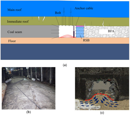
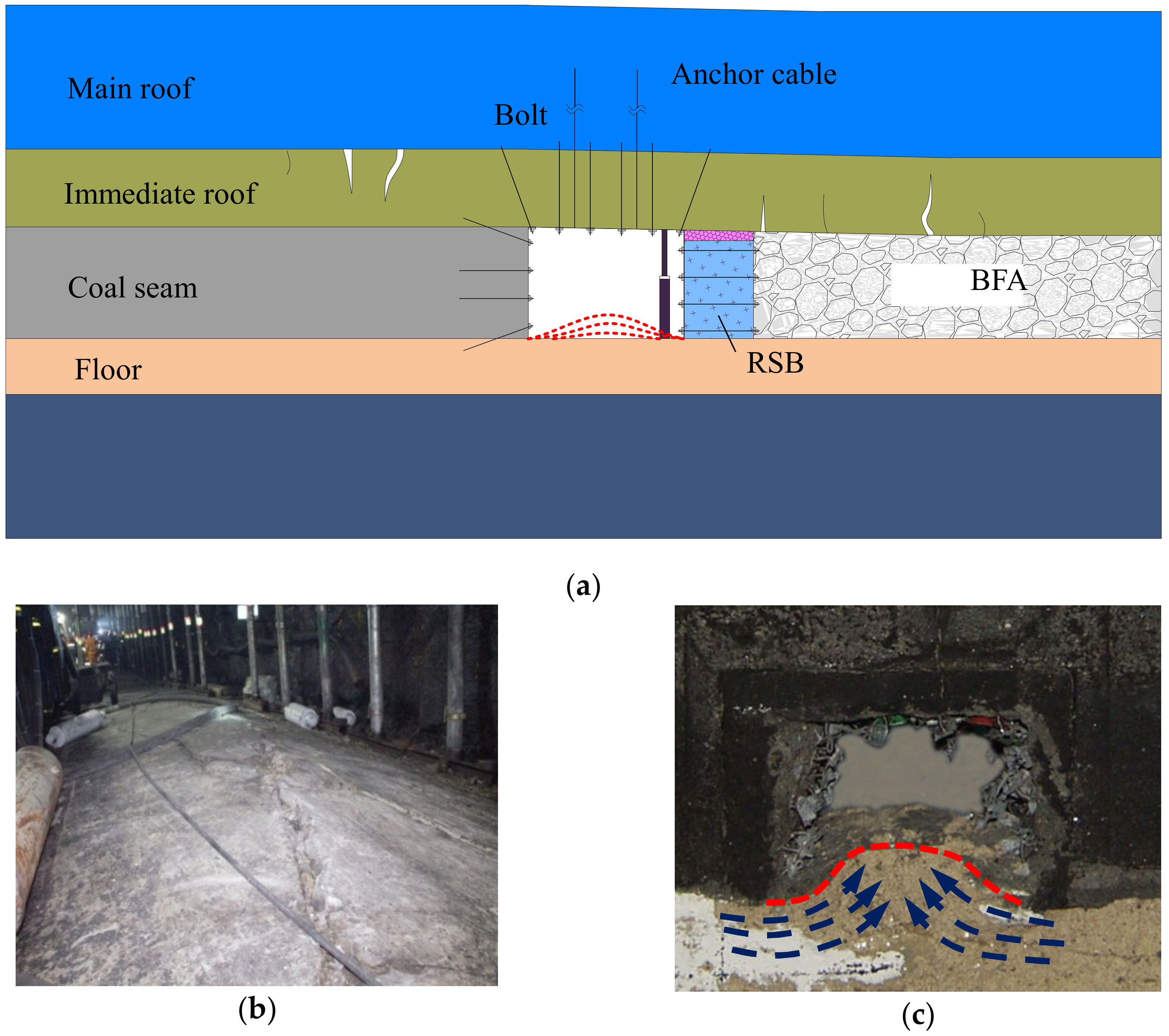
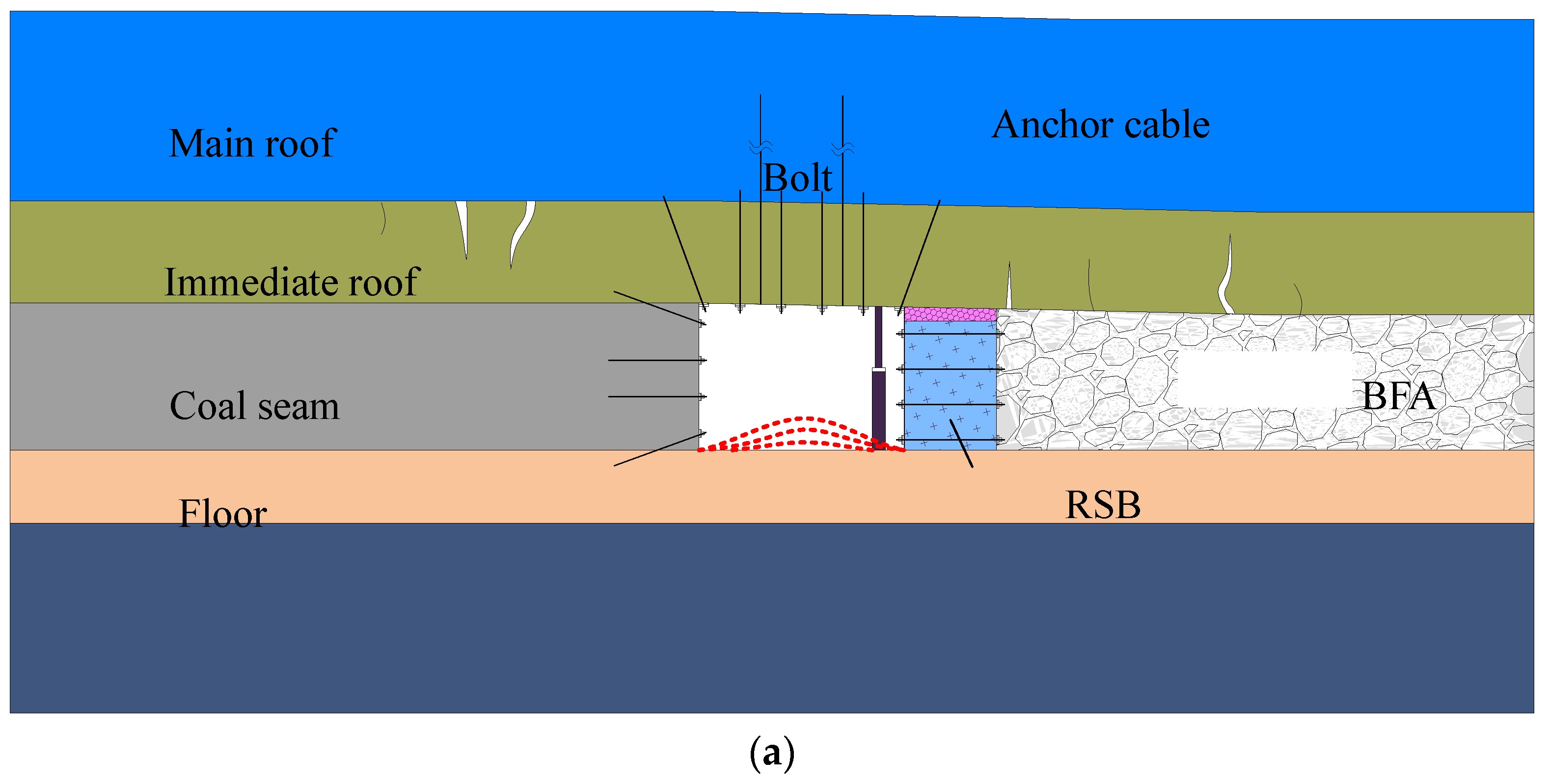
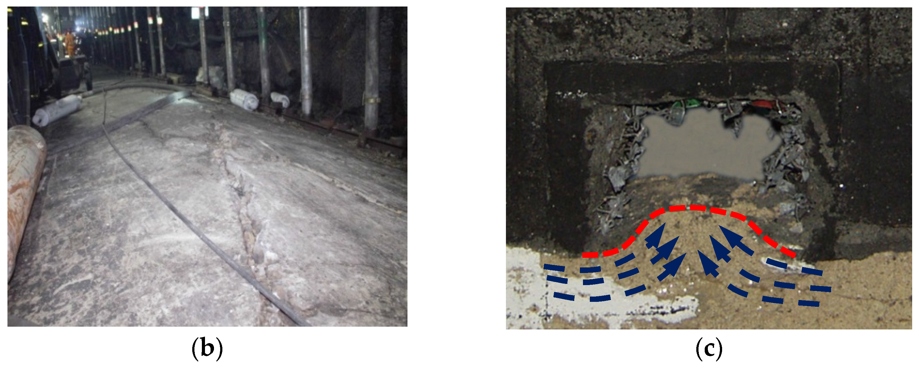
In the gob-backfilled GER engineering (Figure 5a), initially compacted gangues were used to backfill the gob at the right side after the right working face mining, forming the BFA. The RSB was constructed at the gob side of the roadway. The RSB was strengthened with cross anchors on the basis of the original support with bolt and cable in the roadway. The monitoring results show that the large curved fold-type asymmetric floor heave occurs in the absence of water and geological structure when the field retained entry stabilizes (Figure 5b). In addition, this phenomenon was also observed in the physically similar simulation test of strata structure and mining conditions of the test mine without considering the effects of water and geological structure (Figure 5c). Therefore, it can be assumed that the floor heave of gob-backfilled GER is mainly caused by the load on the floor strata when the stresses are redistributed.
The loads that can directly affect the floor heave of gob-backfilled GER mainly include (Figure 6): (1) The vertical load of solid coal on the floor under the influence of mining. The measured data show that the stresses at the solid coal side are nonlinearly distributed in a certain range when the GER enters the stable stage. The area where the stresses are distributed from the surface of the roadway to deep solid coal can be divided into the stress concentration zone (L3, L4) and the original stress zone (L5). The original stress is expressed by γH, where γ is the rock volume weight and H is the coal seam depth. In the stress concentration zone, the stress tends to increase (q3) and decrease (q4) from shallow to deep, then gradually restores to the original stress (q5). The concentration factor of the stress peak point in the stress concentration zone is K; (2) The vertical load (q2) exerted by the BFA (L2) on the floor under compaction. In the gob-backfilled GER, the BFA plays a major role in supporting the roof, which determines the bending subsidence of main roof “large structure”. The area where the stresses are distributed in the BFA can be divided into stress relief zone and stress restoration zone from left to right. The gob can quickly enter the stable compaction state under the backfilling mining conditions. Compared to the condition that roof is managed using caving method, the distribution of the stress relief zone is very small; (3) Transmission of supporting reaction force of RSB (L1) in the direction of the floor. Owing to the support of gangue in the BFA, the main roof is not broken and the overlying strata pressure is transferred down through the main roof. On one hand, the immediate roof adapts to the rotational deformation of the main roof. On the other hand, it suffers a certain bed separation and subsidence. The engineering practice results show that it is not feasible to limit the rotation of the main roof by the support of the RSB. Therefore, a 200-mm flexible cushion is established at the upper part of the RSB, forming a soft-hard RSB structure. On the one hand, it can adapt to the given deformation of the main roof, and on the other hand, it can block gangue, prevent the immediate roof from separating, and control the convergence deformation of the roadway. When the roof load exceeds the strength of the flexible cushion, a large yield deformation occurs in the flexible cushion, preventing the load from transferring to the lower rigid support body. The working load (q1) of the lower rigid RSB can be retained within a reasonable range to avoid the overload damage to the RSB during roof subsidence, which is critical to maintaining the completeness of the RSB; (4) The squeezing action of the horizontal ground stress. The engineering practice under deep mining conditions demonstrated that the lateral pressure coefficient λ is approximately 1.0, and the high horizontal ground stress aggravates the bending deformation of floor strata. The parameters of vertical stress distribution in the roadside can be detected (for the convenience of calculation, q1 is expressed by multiples of γH) by arranging a borehole stress meter at the roadside of the working face of the test mine. See Table 1.
3. Establishment of Mechanical Model for Floor Heave of Gob-Backfilled GER
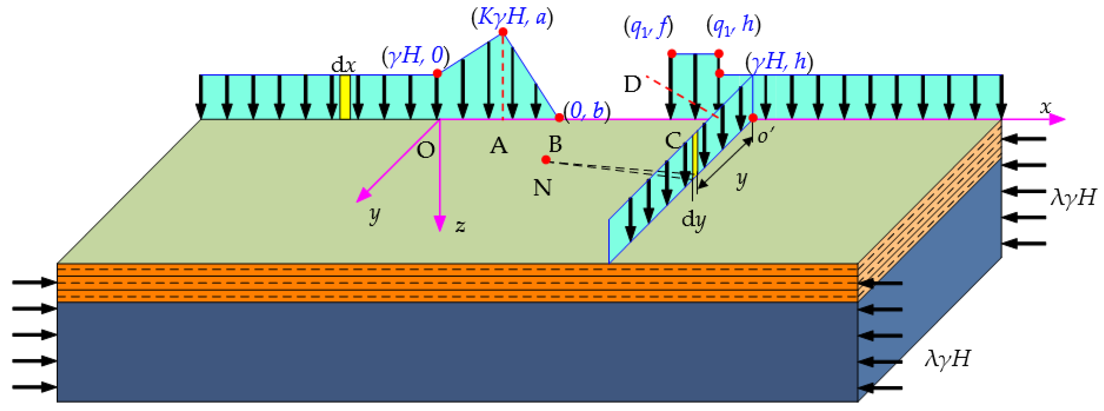
As shown in Figure 7, the space coordinate system is established by setting the junction of the original stress zone and the stress concentration zone in the solid coal as the origin, horizontal right as the positive direction of x-axis, outward axially along the roadway as the positive direction of the y-axis, and vertical down as the positive direction of the z-axis. As the load is evenly distributed in the direction of the y-axis, the mechanical model of the floor can be simplified to the plane strain problem. Through calculation, the vertical linear load distributed in the y direction and the stress caused by the floor at any point N in the XZ plane can be obtained. Under the point load, the stress and deformation at any point of the floor can be obtained:
The distribution of stress at the point N under the evenly-distributed linear load in the y direction is as follows:
The vertical displacement of the floor surface (z = 0) under the evenly-distributed linear load in the y direction is as follows:
where L is the mining influence range axially in the direction of the roadway; R1 is the length of , ; is the evenly-distributed linear load in the y direction; is the Poisson’s ratio of the floor rock; and E is the elastic modulus of the floor rock.
The excavation of the roadway and the mining of the coal seam change the stress distribution in the strata, thus causing the deformation of the surrounding rock. For the floor strata, the stress in the vertical direction of the mined coal seam is changed. The distribution of load in the vertical direction on the floor can be simplified as shown in Figure 7 by detecting the pressure in the surrounding rock in the horizontal direction of the roadway. The vertical stress in the plane XZ is regarded as approximate linearly distributed stress. and are simplified as a triangular load and a trapezoidal load, respectively, and is simplified as an evenly-distributed load. The displacement and the stress state of the floor surface at any point are the result of the superposition of various loads of its upper part at this point. Therefore, the deformation and the stress distribution of the floor after entry retaining are caused by the difference of load before and after coal seam mining.
● Stress distribution of the floor
The additional stress in the floor caused by the triangularly distributed strip load in the stress concentration zone of the solid coal side (OA section) is expressed as follows:
The additional stress in the floor caused by the triangularly distributed strip load in the stress concentration zone of the solid coal side (AB section) is expressed as follows:
The additional stress in the floor caused by the evenly-distributed load in the RSB (CD section) is expressed as follows:
The additional stress in the floor caused by the evenly distributed load in the original stress zone (AC section) is expressed as follows:
The additional stress distribution in the floor after entry retaining is as follows:
The main stress at any point within the range of the floor can be obtained from Equation (9):
where K is the stress concentration factor of the solid coal side, γ is the rock volume weight, H is the coal seam depth, is the load on the upper part of the floor in the OA section. a, b, f, and h are x axis coordinates of points A, B, C, D, respectively.
● Vertical displacement of floor surface
The vertical displacement of the floor surface caused by the triangularly distributed strip load in the stress concentration zone of the solid coal side (OA section) is expressed as follows:
The vertical displacement of the floor surface caused by the triangularly distributed strip load in the stress concentration zone of the solid coal side (AB section) is expressed as follows:
The vertical displacement of the floor surface caused by the evenly-distributed load in the RSB (CD section) is expressed as follows:
The vertical displacement of the floor surface caused by the evenly distributed load in the original stress zone (AC section) is expressed as follows:
The vertical displacement of the floor surface after entry retaining is as follows:
where μ is the Poisson’s ratio of the floor, K is the stress concentration factor of the solid coal side, E is the elastic modulus of the floor rock, and L is the mining influence range in the y direction. γ is the rock volume weight, H is the coal seam depth, is the load on the upper part of the floor in the OA section. a, b, f, and h are x axis coordinates of points A, B, C, D, respectively.
4. Floor Heave Mechanism of Gob-Backfilled GER
4.1. Analysis of Influencing Factors for Floor Heave of Gob-Backfilled GER
It can be seen from Equations (10) and (15) that the stress field and the displacement field of the backfilled GER floor are mainly affected by the following three factors: mining geological conditions, load distribution of solid coal side, and gob-side load distribution. The mining geological conditions include the coal seam depth, elastic modulus of floor rock, internal friction angle, cohesion, etc. The load distribution of the solid coal side is mainly determined by the stress concentration factor of the solid coal side. The load distribution of gob side is mainly affected by the support force of RSB and BFA. The influence of each factor on the stress field and displacement field of floor can be directly analyzed by means of theoretical analysis, providing a basis for designing the control technology for floor heave in backfilled GER.
4.1.1. Influence of Geological Conditions on the Floor
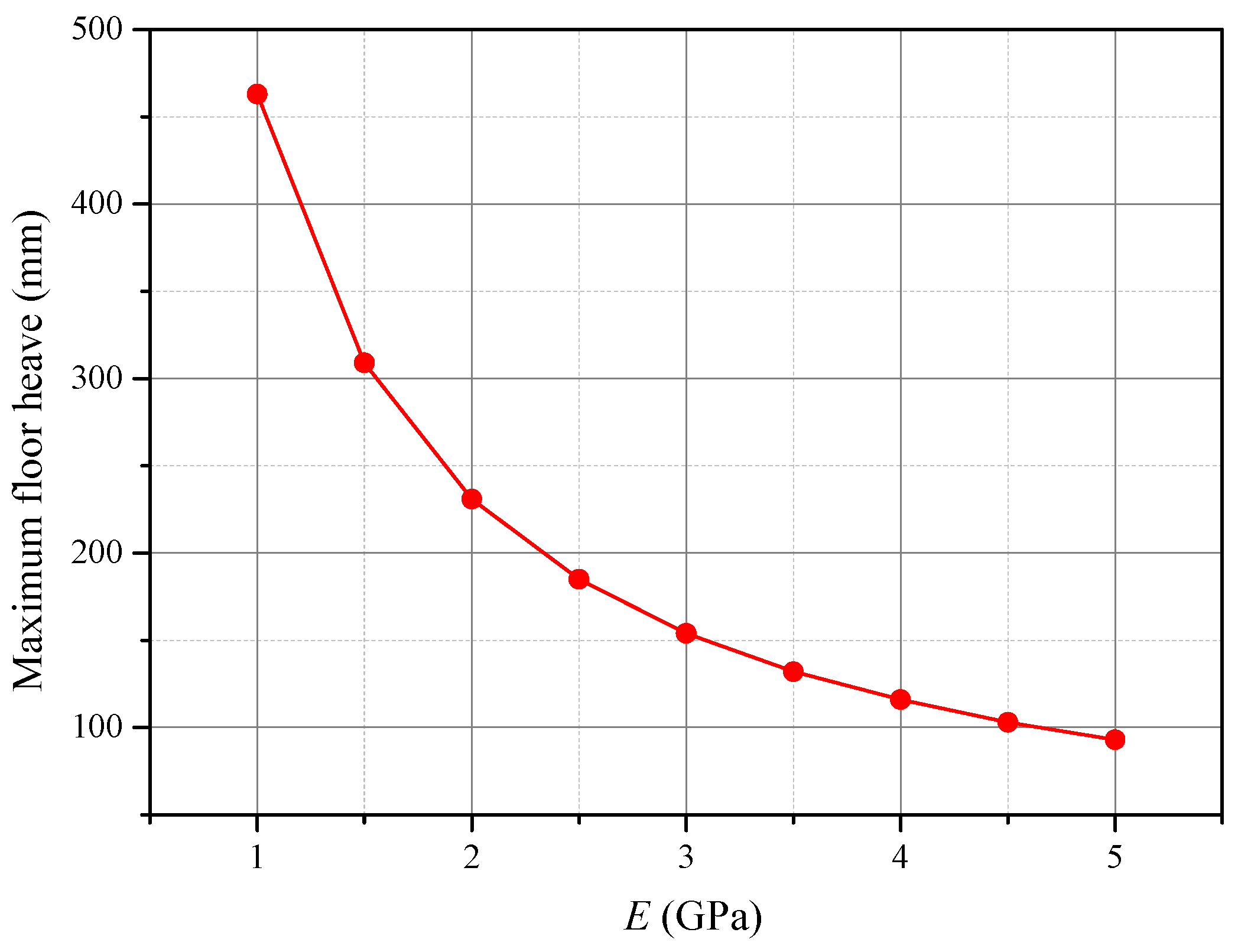
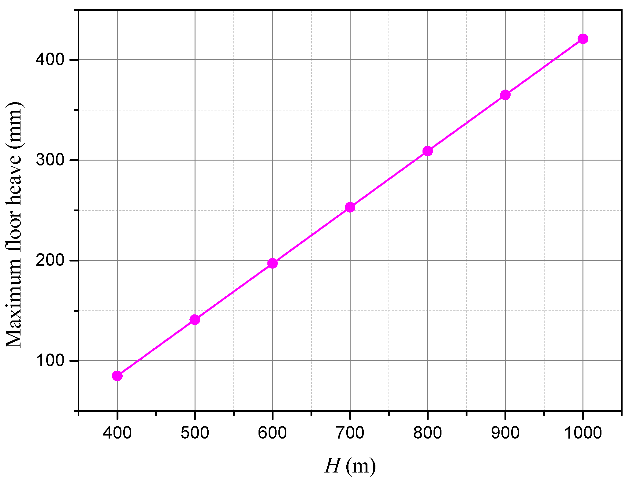
To analyze the influence of each factor on the floor heave characteristics, the elastic modulus, coal seam depth, internal friction angle, and cohesion were analyzed as single factors, under the condition that other conditions were not changed. As shown in Figure 8, under the condition that the burial depth, load, cohesion, and internal friction angle are not changed, the maximum floor heave of GER is inversely proportional to the elastic modulus of the floor rock, actually reflecting the resistance of the floor rock to the deformation under the influence of gob. The maximum floor heave of the roadway increases linearly with the increase of the coal seam depth (Figure 9), which can be seen from Equations (11)–(15). However, there is not a regularly linear relationship between them in practical engineering, mainly due to the plastic deformation of the rock (which has not been considered in the elastic model), but the internal relationship between them can be obtained according to the qualitative analysis in this paper.
In addition, the approximate distribution range of the plastic zone in the floor can be obtained by introducing the yield criterion of floor strata, based on the analytical solution of the stress field of the overall floor, where the yield condition of the floor rock meets the Mohr–Coulomb strength criterion:
Thus, the plastic zone of the floor rock is expressed as:
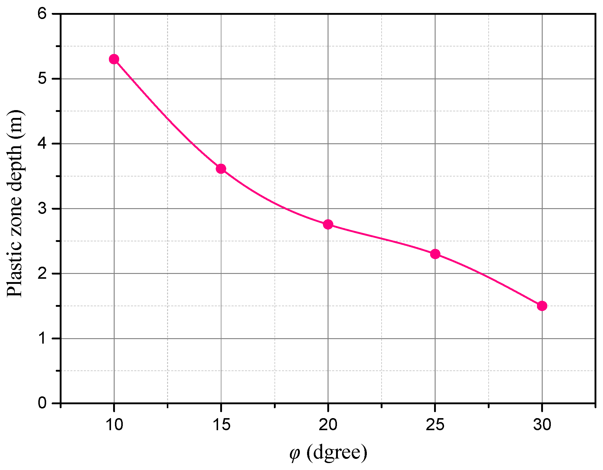
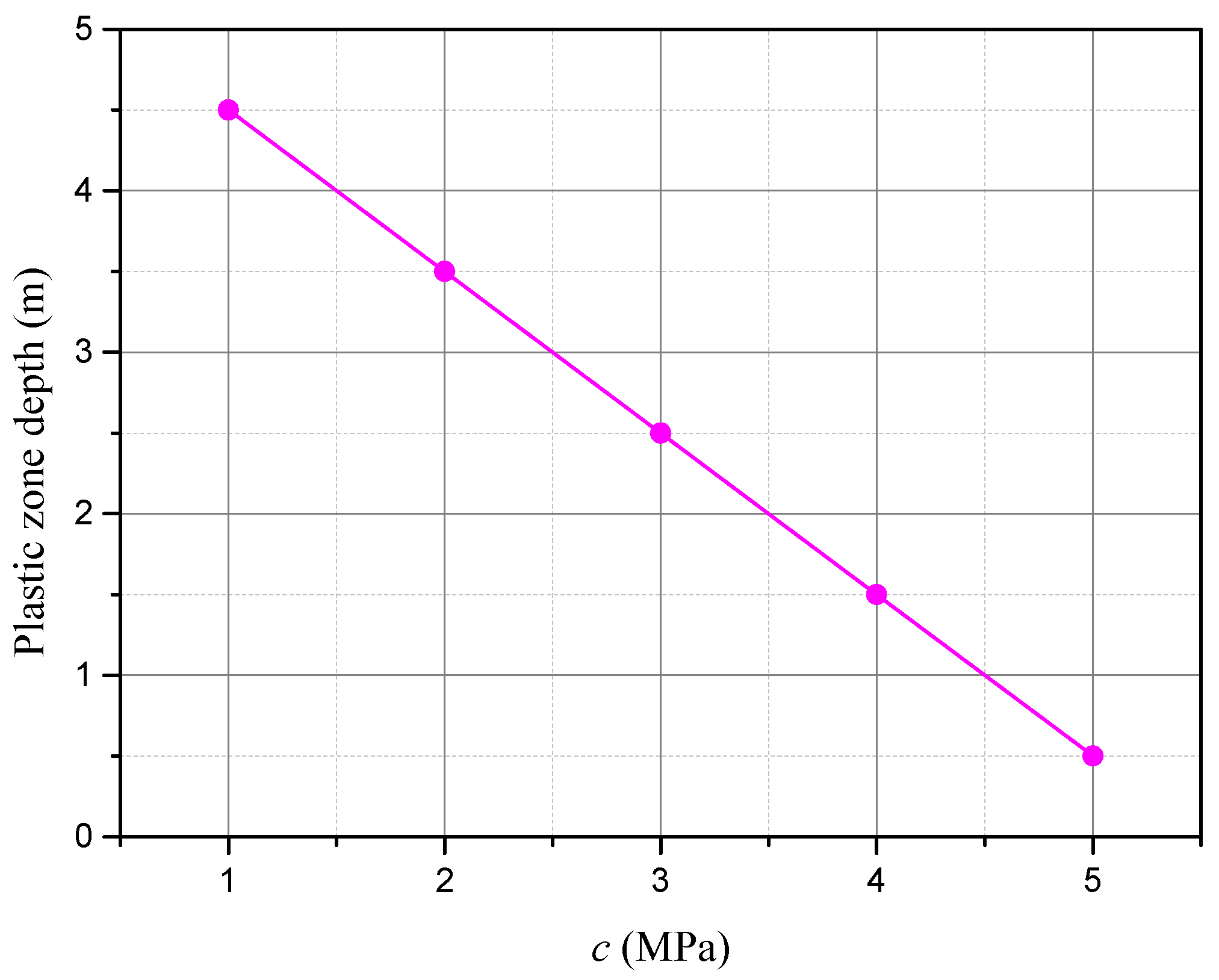
From Equation (16), it can be seen that the cohesion and the internal friction angle of the floor rock have an important effect on the development of the plastic zone in the backfilled GER in addition to the stress distribution law of the floor. It can be seen that the depth of the plastic zone in the floor decreases with the increase of the internal friction angle of the rock through calculation, showing a nonlinear relationship between them (Figure 10). When the internal friction angle increases from 10° to 30°, the depth of the plastic zone in the floor is reduced by 73%. In addition, the depth of the plastic zone decreases linearly with the increase of the cohesion (Figure 11) with a gradient of −1 m/MPa.
4.1.2. Influence of Load of the Solid Coal Side on the Development Depth of the Plastic Zone in the Floor
In addition to the rock characteristic parameters of the floor, the stress field distribution in the two sides of the roadway also has an important effect on the deformation of the floor. When the gob-backfilled GER is completed, the granular gangues in the BFA restore their original rock stress 20 m to the rear of the working face and enter the compaction stable zone under the combined action of the initial pushing of the backfill hydraulic support and the roof subsidence at the late stage, playing a major role in supporting the roof. The supportive effect of the BFA on the roof acts in the condition of roof subsidence, so it is a passive support. Therefore, due to the overall structure of the roof, the given deformation of the roof at the solid coal side will inevitably occur after coal mining, resulting in the concentration of stresses at the solid coal side. The main reason causing the floor heave of the backfilled GER is the redistribution of floor stress after mining and retaining. Therefore, the stress concentration factor of the solid coal side is one of the key factors to determine the stability of the roadway floor.
From Figure 12, it can be seen that the depth of the plastic zone in the floor increases with the increase of the stress concentration factor of the solid coal side. When K is less than 2.0, the increase rate is low; when K is greater than 2.0, the increase rate is high. To control the floor heave, the stress concentration factor of the solid coal side should be minimized. The results [31] of the unconfined compression test of granular gangue show that the axial displacement under axial stress of 2 MPa reaches 80% of that of 6 MPa. Therefore, when the geological conditions and the roadway section remain unchanged during excavation, the initial compaction of granules in the BFA needs to be properly improved to reduce the early deformation of the BFA to limit the rotational deformation of the main roof, to reduce the given deformation of the roof of the solid coal side, and achieve the purpose of reducing the stress concentration factor K.
4.1.3. Influence of Gob-Side Load on the Developmental Depth of the Plastic Zone in the Floor
The load of the gob-side backfilled GER includes the working resistance of the RSB and the vertical stress of the BFA. In Figure 13, indicates the stress level of . It can be seen that the depth of the plastic zone in the floor decreases with the increase of the support reverse force of the RSB. The depth of the plastic zone decreases rapidly when is within 0.5–1.5, but decreases slowly when is within 1.5–2.3. Therefore, it can be assumed that the increase of the support force of the RSB is favorable to the control of floor heave when is less than 1.5. In addition, the proper reduction of backfilling pressure near the side of the roadway in the BFA can transfer the pressure from the plastic area in the floor to the side of the BFA, thus providing a new channel for floor deformation and pressure release, which is favorable for the control of floor heave in the roadway.
4.2. Floor Heave Mechanism of Working Face in Gob-Backfilled GER of the Test Mine
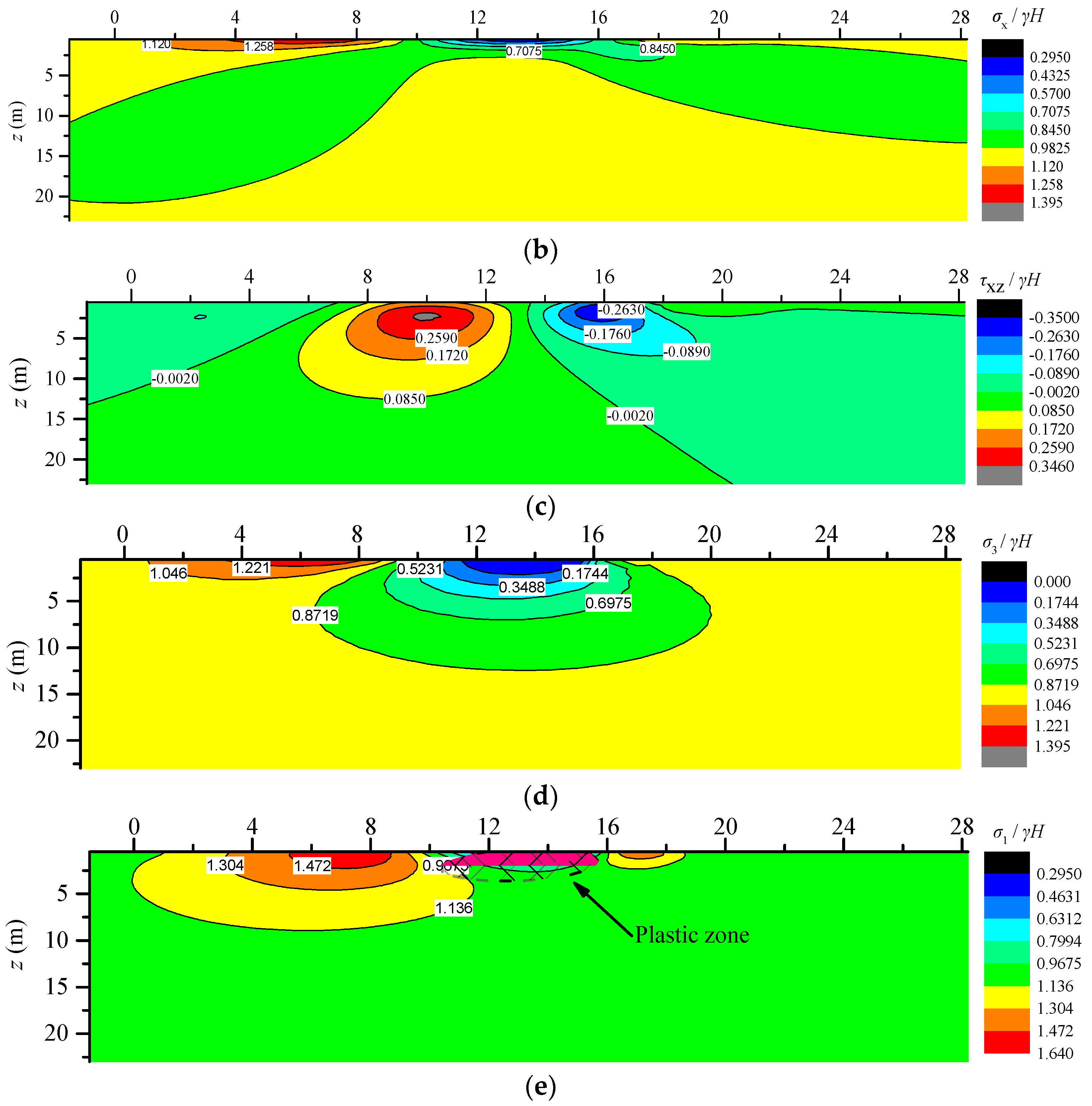
The distributions of stresses in the rock floor can be obtained from Equation (9), including the vertical stress (Figure 14a), the horizontal stress (Figure 14b), and the shear stress in the xz direction of the floor (Figure 14c). Then, the minimum principal stress (Figure 14d), the distribution of the maximum principal stress, and the plastic zone of the floor strata (Figure 14e) can be obtained from Equation (10). From Figure 8, it can be seen that the relief area of vertical stress of the floor is mainly distributed in the range from the floor surface of the roadway to a depth of 22.8 m, deflecting to the solid coal side at the shallow, and the gob side at the deep. The stress distribution of the floor surface is given by the load. Through calculation, the distribution range of the vertical stress-increasing zone of the floor significantly increases with the increase of the stress concentration factor of the solid coal side, support load of RSB, and their action range. The stress concentration factor of the test mine is 1.53, and the support load of RSB is 1.3γH. Through calculation, the influence depth of the vertical stress-increasing zone below solid coal is 7.3 m, and that of the RSB floor is 2.3 m. The influence range of horizontal stress mainly extended to both sides in the direction of the base angle of the roadway. The influence area of shearing stress of the floor is mainly distributed in the abrupt change region of the load on the floor surface, including the stress concentration zone of the solid coal side and the floor area below the RSB.
The change of minimum principal stress of the floor mainly lies in the bottom of the roadway, and its depth is much larger than the floor on both sides of the roadway. The maximum principal stress mainly increases below the stress concentration zone of the solid coal side and decreases below the roadway with a small distribution range and a depth of 2 m. The values of the maximum and minimum principal stresses of the floor are positive, indicating that the principal stress in the relief zone of the roadway floor is compressive stress. The distribution of the plastic zone in the floor can be obtained as shown in Figure 14e by submitting the measured parameters of the test mine in Table 1 into Equation (16). The development depth of the plastic zone in the floor is 2.68 m. In addition, the angle between the maximum principal stress and the x direction and the angle between the minimum principal stress and the x direction can be calculated with the following equation:
The results show that the direction of the maximum principal stress in the stress relief zone beneath the roadway is almost parallel to the x-axis. The horizontal stress of the floor in the roadway is the external factor directly causing floor heave in the roadway. Other external factors affect the failure characteristics of the roadway floor by changing the horizontal stress of the floor in the roadway. Compared with the general roadway where the roof is managed using the caving method, the difference in the load of the floor at the gob side is the main reason leading to the difference in the deformation characteristics of roadway floor. Under normal conditions, the gob area is in an uncompacted state, the plastic zone and the stress relief zone of the floor are shifted to the gob side. As the floor in the gob is not limited in the vertical direction, the floor stress and deformation are released along the gob floor, reducing horizontal stresses of the roadway floor to a certain degree. In the backfilled GER engineering, the horizontal stress of the roadway floor is large due to the constraints in the vertical direction of the BFA. Therefore, slots with a certain depth can be excavated in the roadway floor to reduce the horizontal stress of the floor by absorbing the horizontal deformation of the floor via the stress relief slots to control the floor heave.
5. Field Test and Monitoring
5.1. Control Principle of Floor Heave
Based on the above analysis results, the following suggestions can be proposed for the design of process parameters and floor heave control scheme of backfilled GER in practice engineering:
- (1)
- With respect to improving the mechanical properties of floor strata: the deformation of the floor decreases with the increase of the elastic modulus of the floor rock, and the development depth of the plastic zone decreases with the increase of c and φ value. Based on the above results, the broken soft rock in the plastic zone of the floor can be performed with grouting reinforcement and repair to improve their elastic modulus and c, φ values, reducing the plastic zone of the floor and controlling the floor deformation (Figure 15a). In addition, the length, angle, and other parameters of floor grouting pipe can be rationally designed according to the developing depth and distribution characteristics of the plastic zone.
- (2)
- With respect to increasing the minimum principal stress of the roadway floor: the principal stress of the roadway floor is compressive stress, and squeezing action is exerted in the roadway. Therefore, the floor can be poured with a concrete-forming counter-arched slab to optimize the load-bearing structure of the floor and improve its flexural rigidity. Meanwhile, according to the calculation results of the distribution of the plastic zone in the floor under different conditions, anchor bolts are set from the counter-arched floor to the deep surrounding rock and fixed in the elastic zone of the floor; that is, the length of the bolts should be greater than the calculated value of the depth of the plastic zone in the floor (Figure 15b). Therefore, the concrete-poured floor can be integrated with the deep intact rock through the tension of the bolts, increasing the minimum principal stress of the floor, optimizing the stress environment of the floor and reducing the floor heave in the roadway.
- (3)
- With respect to reducing the maximum principal stress of the roadway floor: the horizontal stress of the floor on the roadway is the external factor causing floor heave in the roadway, and thus stress relief slots can be arranged on the floor to reduce the principal stress in the horizontal direction of the roadway (Figure 15c). The depth of the stress relief zone can refer to the calculated distribution range of the relief zone of the maximum horizontal stress. In addition, the stress relief slots should be arranged near the solid coal side. The reason is that the stress relief slots provide two free surfaces for the floor rock to release deformation in the horizontal direction. The horizontal displacement of the floor near the stress relief slot is the superposition of the deformation in the horizontal direction of each position. The maximum horizontal displacement of the roadway floor should occur near the stress relief slot under the action of horizontal stress. Therefore, when the distance between the stress relief slot and the RSB is small, the horizontal displacement of the lower part of the RSB increases, which is not conducive to the stability of the RSB.
- (4)
- With respect to optimizing the upper load of the floor: the horizontal pushing force of the backfill hydraulic support on the rear BFA is improved to increase the initial compaction of the granular gangue in the BFA and reduce the initial subsidence of the roof at the gob side, and thus, to decrease the given deformation of the roof at the solid coal side and reduce the stress concentration factor K of the solid coal side. In addition, the working resistance of the RSB at the gob side should be appropriately improved. Meanwhile, the horizontal pushing force of the hydraulic support is adjusted, and the support pressure of the BFA close to the roadway side is reduced to move the plastic zone of the floor to the gob side, and provide new channels for the release of deformation and stress of the floor in the gob, which is favorable for maintaining the stability of the floor in the roadway.
5.2. Design of the Floor Heave Control Scheme
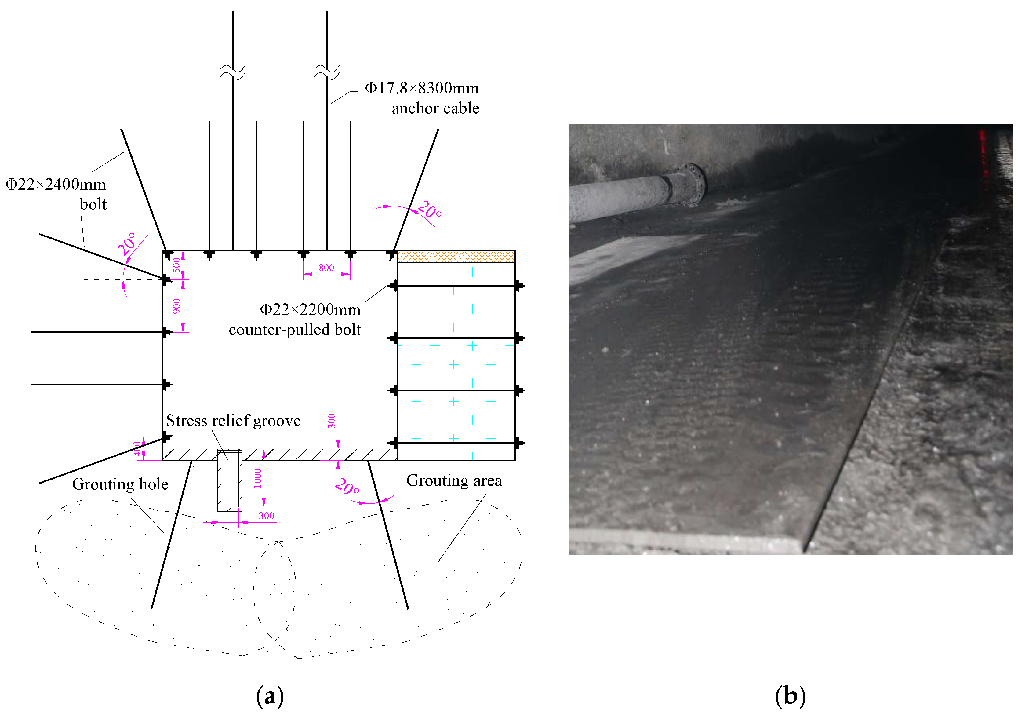
C30 concrete was used to pour into a hardened floor with a thickness of 300 mm in the working face of the test mine under the original support scheme, resulting in a large floor heave after the completion of entry retaining (Figure 5b). Based on the above design principles and the geological conditions of the mine, a floor heave control scheme for the working face of the gob-backfilled GER in the test mine was proposed. The field application effect was tracked and monitored. The floor heave control scheme (Figure 16a) is designed as follows:
- (1)
- The horizontal pushing force of three end backfill hydraulic supports at the working surface close to the side of the roadway is eliminated, which is favorable for the movement and deformation release of the plastic zone in the floor of the roadway.
- (2)
- Holes are drilled in the roadway floor 500 mm away from the two sides for grouting. Grouting holes are set outside of the roadway by 20° with a depth of 2.6 m and a grouting pressure of 2 MPa. Cement grout is used with cement label of P.O. 42.5 and a water-cement ratio of 1:0.8. Through the diffusion of the grout, the deep plastic zone in the floor is reinforced to carry the horizontal pressure of the floor of the roadway.
- (3)
- Stress relief slots are arranged on the floor 100 mm away from the solid coal side of the roadway. The stress relief slots are 300 mm wide and 700 mm deep. As the surface of roadway floor is a free surface and the maximum principal stress of the shallow floor is distributed in the horizontal direction, the bearing structure determines that the shallow surrounding rock of the floor does not have high carrying capacity. Therefore, stress relief slots are arranged in the shallow rock to provide space for the deformation release of the shallow floor in the horizontal direction, which can effectively reduce its maximum principal stress and ensure the completeness of the floor surface of the roadway.
- (4)
- A 300-mm thick hardening layer is formed on the floor surface by concrete pouring. The concrete strength of the hardening layer is C30. Steel plates are laid at the location of stress relief slot on the concrete surface.
5.3. Field Monitoring
To analyze the effect of the new floor heave control scheme of gob-backfilled GER, measuring stations were arranged on the roadway to record the convergence deformation during advancement of the working face. The roof-floor displacement of the roadway was larger than the two-side displacement during advancement of the working face. The maximum roof-floor displacement was 427 mm, of which the floor heave was 320 mm by the original support scheme. After adopting the new scheme, the maximum roof-floor displacement was 112 mm, which was 73.8% lower than that with the original support scheme. The roadway section meets the design and utilization requirements when the deformation stabilizes (Figure 16b). The field test results show that the control principles of floor heave of gob-side backfilled GER based on the theoretical model in this paper have been successfully applied in the field construction.
6. Conclusions
To counter the serious floor heave of GER with fully-mechanized backfilling mining, a theoretical calculation model for the gob-backfilled GER was established. The influence of the mechanical properties of floor strata, the granular compaction of BFA, the vertical support of RSB, and the stress concentration of solid coal on floor heave in the gob-backfilled GER was studied. The following conclusions are drawn:
- (1)
- The theoretical model established herein can be used to obtain the analytical expressions of the stress field and displacement field in the vertical and horizontal directions of the floor strata, and thus to obtain the distribution law of the principal stress field and plastic zone of the floor, providing an effective means for directly analyzing the floor heave mechanism of GER.
- (2)
- The parametric analysis results show that the maximum floor heave of the roadway increases with the increase of the coal seam depth, and decreases with the increase of the elastic modulus of the floor rock. The development depth of the plastic zone in the roadway floor decreases with the increase of the c and φ value of the floor rock and the support resistance of the RSB, and increases with the increase of the stress concentration factor of the solid coal side.
- (3)
- The distribution results of the stress field and the plastic zone of the floor in the gob-backfilled GER of the test mine show that the development depth of the plastic zone in the test mine is 2.68 m. The horizontal stress of the floor in the roadway is the external factor directly causing floor heave in the roadway. Other external factors affect the failure characteristics of roadway floor by changing the horizontal stress of the floor in the roadway.
- (4)
- Based on the theoretical analysis results, floor heave can be effectively controlled by improving the mechanical properties of floor strata, adjusting the principal stress of the floor and optimizing the upper load of the floor. The field test and monitoring results show that the comprehensive control scheme of adjusting backfilling pressure, deep grouting reinforcement, shallow opening stress relief slots, and surface pouring can effectively control the floor heave of the gob-backfilled GER. The roadway section meets the design and application requirements when the deformation stabilizes. The research results overcome the technical bottleneck of floor heave control in gob-backfilled GER, providing a reliable basis for the design of the floor heave control scheme.
Acknowledgments
This work is supported by the National Natural Science Foundation of China (Nos. 51323004, 51674250, 51074163, 51574228); Major Program of National Natural Science Foundation of China (No. 50834005, 51734009); the Graduate Innovation Fund Project of Jiangsu Province (No. CXZZ13_0924); Open Fund of State Key Laboratory for Geomechanics and Deep Underground Engineering (SKLGDUEK1409).
Author Contributions
All the authors contributed to this work. Peng Gong and Zhanguo Ma conceived and established the theoretical model; Xiaoyan Ni and Peng Gong deduced the formula; and Ray Ruichong Zhang and Xiaoyan Ni analyzed the data; Peng Gong wrote the paper.
Conflicts of Interest
The authors declare no conflict of interest.
References
- Yang, H.; Cao, S.; Wang, S.; Fan, Y.; Wang, S.; Chen, X. Adaptation assessment of gob-side entry retaining based on geological factors. Eng. Geol. 2016, 209, 143–151. [Google Scholar] [CrossRef]
- Xue, J.H.; Han, C.L. Strata behavior and control countermeasures for the gob-side entry retaining in the condition of large mining height. J. Min. Saf. Eng. 2012, 29, 466–473. [Google Scholar]
- Dong, Z.; Xie, M.; Xian, M. Simulation on roof activities of gob-side entry retaining in fully-mechanized top-coal caving faces. J. China Univ. Min. Technol. 2001, 30, 261–264. [Google Scholar]
- Lu, Y.; Zuo, S.; Ge, Z.; Xiao, S.; Cheng, Y. Experimental study of crack initiation and extension induced by hydraulic fracturing in a tree-type borehole array. Energies 2016, 9, 514. [Google Scholar] [CrossRef]
- Lu, Y.; Cheng, Y.; Ge, Z.; Cheng, L.; Zuo, S.; Zhong, J. Determination of fracture initiation locations during cross-measure drilling for hydraulic fracturing of coal seams. Energies 2016, 9, 358. [Google Scholar] [CrossRef]
- Chen, Y.; Bai, J.B.; Wang, X.Y.; Ma, S.Q.; Xu, Y.; Bi, T.F.; Yang, H.Q. Support technology research and application inside roadway of gob side entry retaining. J. China Coal Soc. 2012, 37, 903–910. [Google Scholar]
- Jiang, B.; Wang, L.; Lu, Y.; Gu, S.; Sun, X. Failure mechanism analysis and support design for deep composite soft rock roadway: A case study of the yangcheng coal mine in china. Shock Vib. 2015, 2015. [Google Scholar] [CrossRef]
- Feng, X.; Zhang, N.; Gong, L.; Xue, F.; Zheng, X. Application of a backfilling method in coal mining to realise an ecologically sensitive “black gold” industry. Energies 2015, 8, 3628–3639. [Google Scholar] [CrossRef]
- Ma, Z.; Gu, R.; Huang, Z.; Peng, G.; Zhang, L.; Ma, D. Experimental study on creep behavior of saturated disaggregated sandstone. Int. J. Rock Mech. Min. Sci. 2014, 66, 76–83. [Google Scholar] [CrossRef]
- Miao, X.X.; Zhang, J.X. Analysis of strata behavior in the process of coal mining by gangue backfilling. J. Min. Saf. Eng. 2007, 24, 379–382. [Google Scholar]
- Sheshpari, M. A review of underground mine backfilling methods with emphasis on cemented paste backfill. Electron. J. Geotech. Eng. 2015, 20, 5183–5208. [Google Scholar]
- Jehring, M.M.; Bareither, C.A. Tailings composition effects on shear strength behavior of co-mixed mine waste rock and tailings. Acta Geotech. 2016, 11, 1–20. [Google Scholar] [CrossRef]
- Huang, Y.L.; Li, J.M.; Song, T.Q.; Kong, G.Q.; Li, M. Analysis on filling ratio and shield supporting pressure for overburden movement control in coal mining with compacted backfilling. Energies 2017, 10, 31. [Google Scholar] [CrossRef]
- He, M.C.; Zhang, G.F.; Wang, G.L.; Xu, Y.L.; Wu, C.Z.; Tang, Q.D. Research on mechanism and application to floor heave control of deep gateway. Chin. J. Rock Mech. Eng. 2009, 28, 2593–2598. [Google Scholar]
- Lin, D.; Wei, X.; Chunzhao, X.U.; Tang, B. Research on the type and deformation mechanism of floor heave of swelling soft rock roadway along goaf in deep mine. Min. Res. Dev. 2013, 33, 23–26. [Google Scholar]
- Sun, X.M.; Chen, F.; He, M.C.; Gong, W.L.; Xu, H.C.; Lu, H. Physical modeling of floor heave for the deep-buried roadway excavated in ten degree inclined strata using infrared thermal imaging technology. Tunn. Undergr. Space Technol. 2017, 63, 228–243. [Google Scholar] [CrossRef]
- Tang, S.B.; Tang, C.A. Numerical studies on tunnel floor heave in swelling ground under humid conditions. Int. J. Rock Mech. Min. Sci. 2012, 55, 139–150. [Google Scholar] [CrossRef]
- Li, X.; Weng, L. Numerical investigation on fracturing behaviors of deep-buried opening under dynamic disturbance. Tunn. Undergr. Space Technol. 2016, 54, 61–72. [Google Scholar] [CrossRef]
- Zhang, N.; Yuan, L.; Han, C.; Xue, J.; Kan, J. Stability and deformation of surrounding rock in pillarless gob-side entry retaining. Saf. Sci. 2012, 50, 593–599. [Google Scholar] [CrossRef]
- Gong, P.; Ma, Z.; Zhang, R.R.; Ni, X.; Liu, F.; Huang, Z. Surrounding rock deformation mechanism and control technology for gob-side entry retaining with fully mechanized gangue backfilling mining: A case study. Shock Vib. 2017, 2017, 1–15. [Google Scholar] [CrossRef]
- Zhang, Z.; Bai, J.; Chen, Y.; Yan, S. An innovative approach for gob-side entry retaining in highly gassy fully-mechanized longwall top-coal caving. Int. J. Rock Mech. Min. Sci. 2015, 80, 1–11. [Google Scholar] [CrossRef]
- Han, C.L.; Zhang, N.; Li, B.Y.; Si, G.Y.; Zheng, X.G. Pressure relief and structure stability mechanism of hard roof for gob-side entry retaining. J. Cent. South Univ. 2015, 22, 4445–4455. [Google Scholar] [CrossRef]
- Song, Z.Q.; Cui, Z.D.; Xia, H.C.; Tang, J.Q.; Wen, Z.J. The fundemental theoretial and engineering research on the green safe no coal pillar mining model by mainly using coal gangue backfill. J. China Coal Soc. 2010, 35, 705–710. [Google Scholar]
- Yong, C.; Bai, J.; Shuai, Y.; Ying, X.; Wang, X.; Ma, S. Control mechanism and technique of floor heave with reinforcing solid coal side and floor corner in gob-side coal entry retaining. Int. J. Min. Sci. Technol. 2012, 22, 832–836. [Google Scholar]
- Han, C.L.; Zhang, N.; Qian, D.Y.; Xue, B. Optimization analysis of span-depth ratio for roof safety control in gob-side entry retaining under large mining height. J. Min. Saf. Eng. 2013, 30, 348–354. [Google Scholar]
- Zhang, N.; Han, C.L.; Han, J.G.; Zheng, X.G. Theory and practice of surrounding rock control for pillarless gob-side entry retaining. J. China Coal Soc. 2014, 39, 1635–1641. [Google Scholar]
- Jiang, B.; Wang, Q.; Li, S.C.; Ren, Y.X.; Zhang, R.X.; Wang, H.T.; Zhang, B.; Pan, R.; Shao, X. The research of design method for anchor cables applied to cavern roof in water-rich strata based on upper-bound theory. Tunn. Undergr. Space Technol. 2016, 53, 120–127. [Google Scholar] [CrossRef]
- Dai, Y.S.; Tan, Y.H.; Wu, J.H.; Wang, Y.; Lu, C.H. Properties of bolt-grouting mortar modified with mineral bauxite by chemical activation. J. Mater. Civ. Eng. 2016, 28, 4016057. [Google Scholar] [CrossRef]
- Cao, P.; Haoyue, L.I.; Zhong, Y.; Wang, F. Mechanism and control of floor heave of deep buried roadway with high lateral pressure coefficient. J. Cent. South Univ. 2017, 48, 457–464. [Google Scholar]
- Sun, J. Numerical simulation of grooving method for floor heave control in soft rock roadway. Int. J. Min. Sci. Technol. 2011, 21, 49–56. [Google Scholar]
- Ma, Z.; Huang, Z.; Fan, J.; Zhao, G.; Sun, K.; Liu, F. Experimental research on compacting characteristics of open-air slag mixture. China Coal 2012, 38, 36–38. [Google Scholar]
Figure 1.
Working face layout of gob-side entry retaining (GER) with fully-mechanized gangue backfilling mining. BFA: backfilling area; RSB: roadside support body.
Figure 1.
Working face layout of gob-side entry retaining (GER) with fully-mechanized gangue backfilling mining. BFA: backfilling area; RSB: roadside support body.

Figure 2.
Field floor heave of gob-backfilled GER. (a) Floor heave affects the roadway transportation; and (b) floor water inrush.
Figure 2.
Field floor heave of gob-backfilled GER. (a) Floor heave affects the roadway transportation; and (b) floor water inrush.
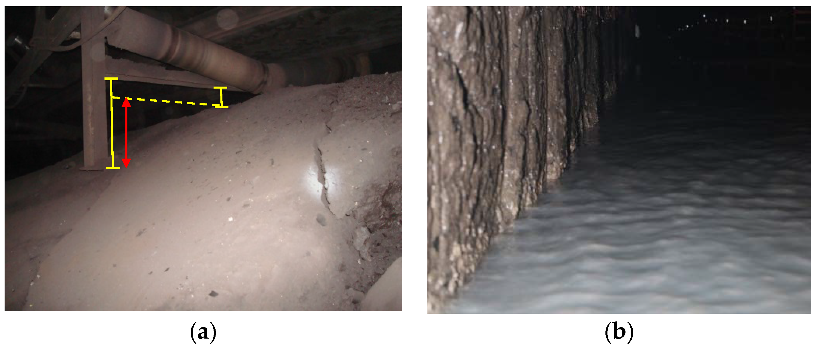
Figure 3.
Location of the test coal mine.
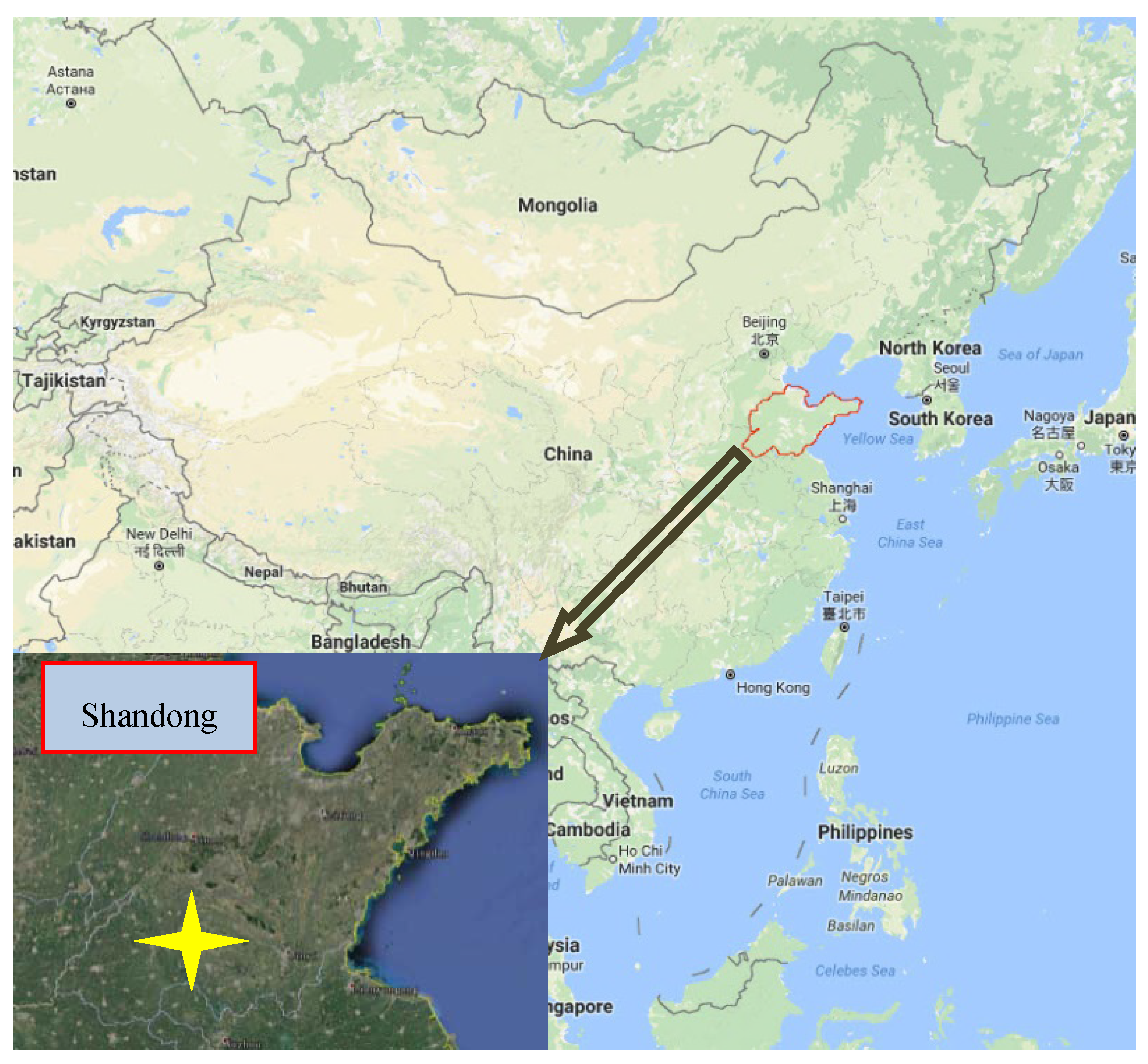
Figure 4.
Stratigraphic column and geological description.
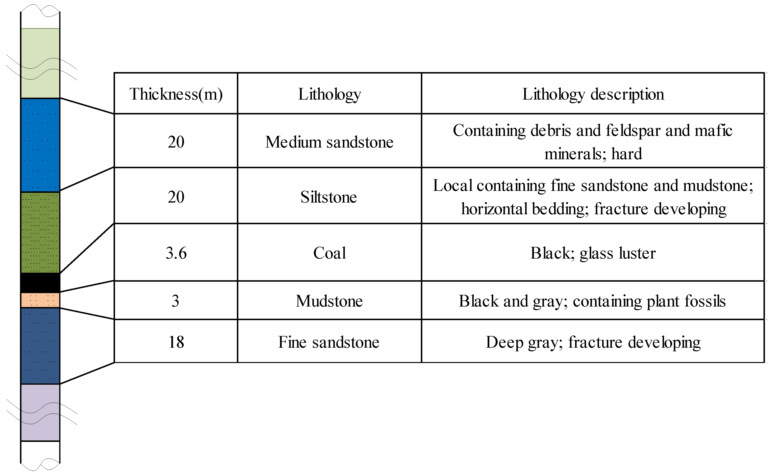
Figure 5.
Diagram of the floor heave in gob-backfilled GER. (a) Diagram of the gob-backfilled GER section; (b) Floor heave in the field GER; and (c) Floor heave of GER in a similar model.
Figure 5.
Diagram of the floor heave in gob-backfilled GER. (a) Diagram of the gob-backfilled GER section; (b) Floor heave in the field GER; and (c) Floor heave of GER in a similar model.


Figure 6.
Source of the floor stress of gob-backfilled GER.
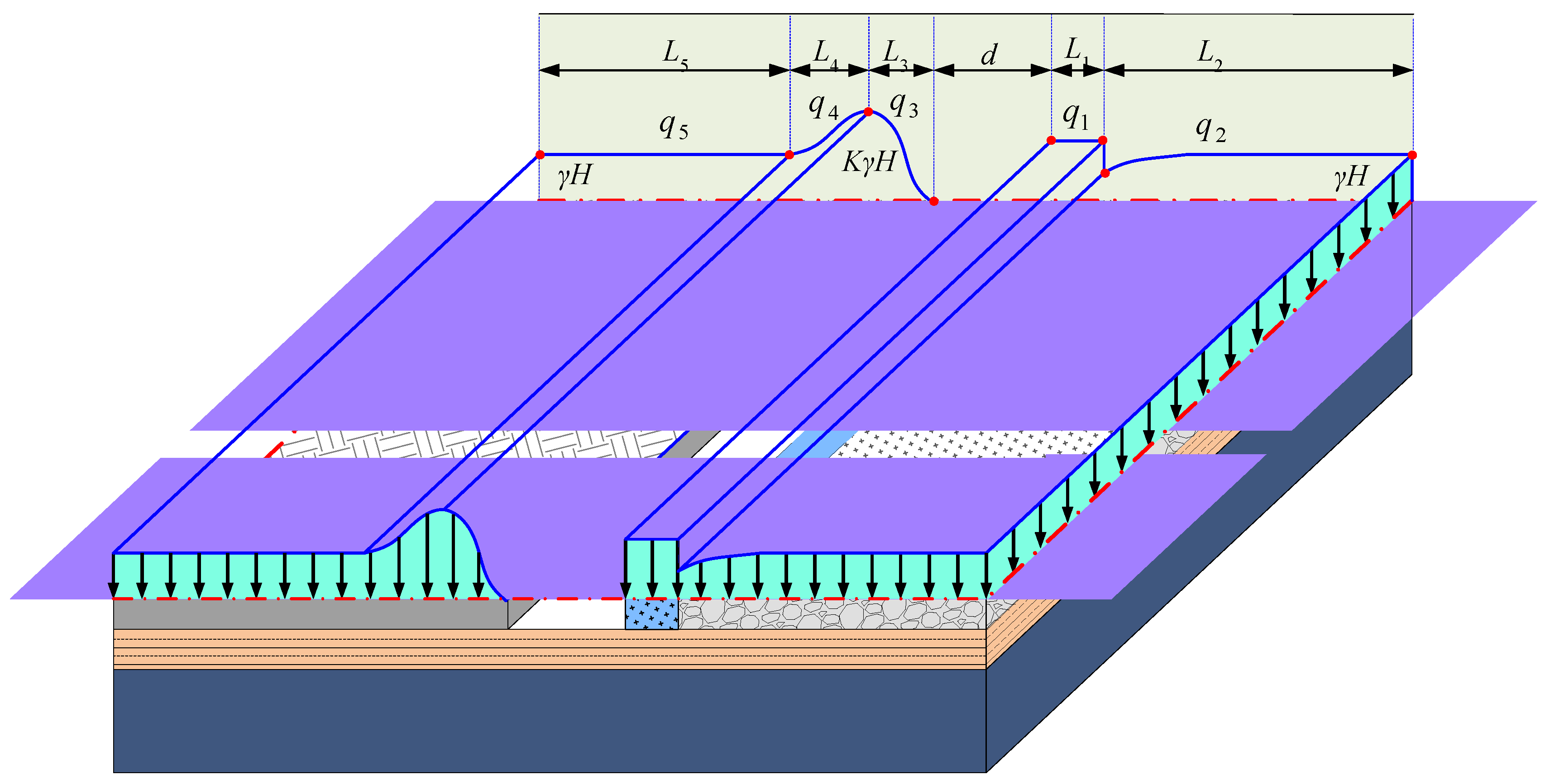
Figure 7.
Mechanical analysis of the floor in gob-backfilled GER.

Figure 8.
Influence of the elastic modulus on the maximum floor heave.

Figure 9.
Influence of the coal seam depth on the maximum floor heave.

Figure 10.
Influence of the internal friction angle on the depth of the plastic zone.

Figure 11.
Influence of the cohesion on the depth of the plastic zone.

Figure 12.
Influence of the stress concentration factor of solid coal on the depth of the floor plastic zone.
Figure 12.
Influence of the stress concentration factor of solid coal on the depth of the floor plastic zone.
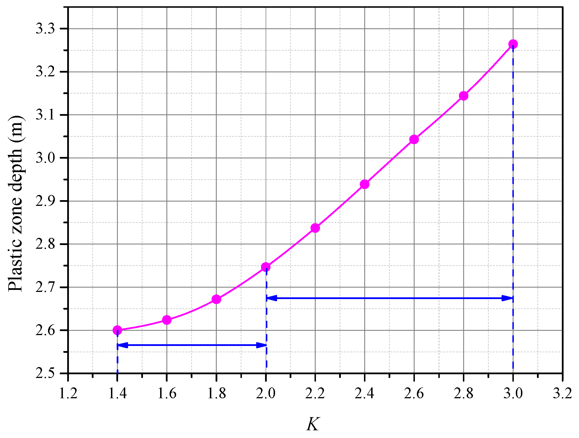
Figure 13.
Influence of resistance of RSB on the depth of the plastic zone in the floor.
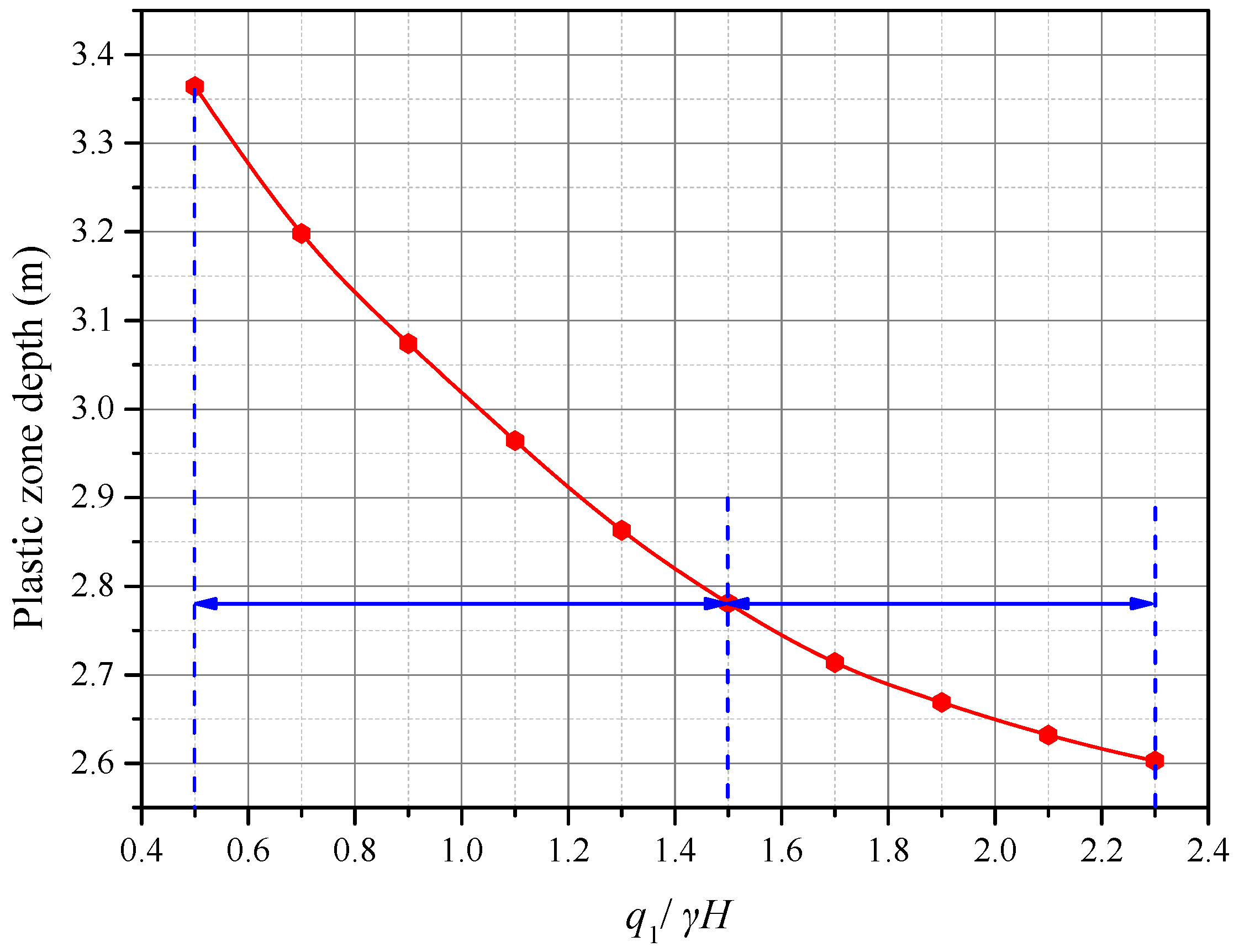
Figure 14.
Stress distribution in the floor of the gob-backfilled GER in the test mine. (a) ; (b) ; (c) ; (d) ; and (e) and the plastic zone.
Figure 14.
Stress distribution in the floor of the gob-backfilled GER in the test mine. (a) ; (b) ; (c) ; (d) ; and (e) and the plastic zone.
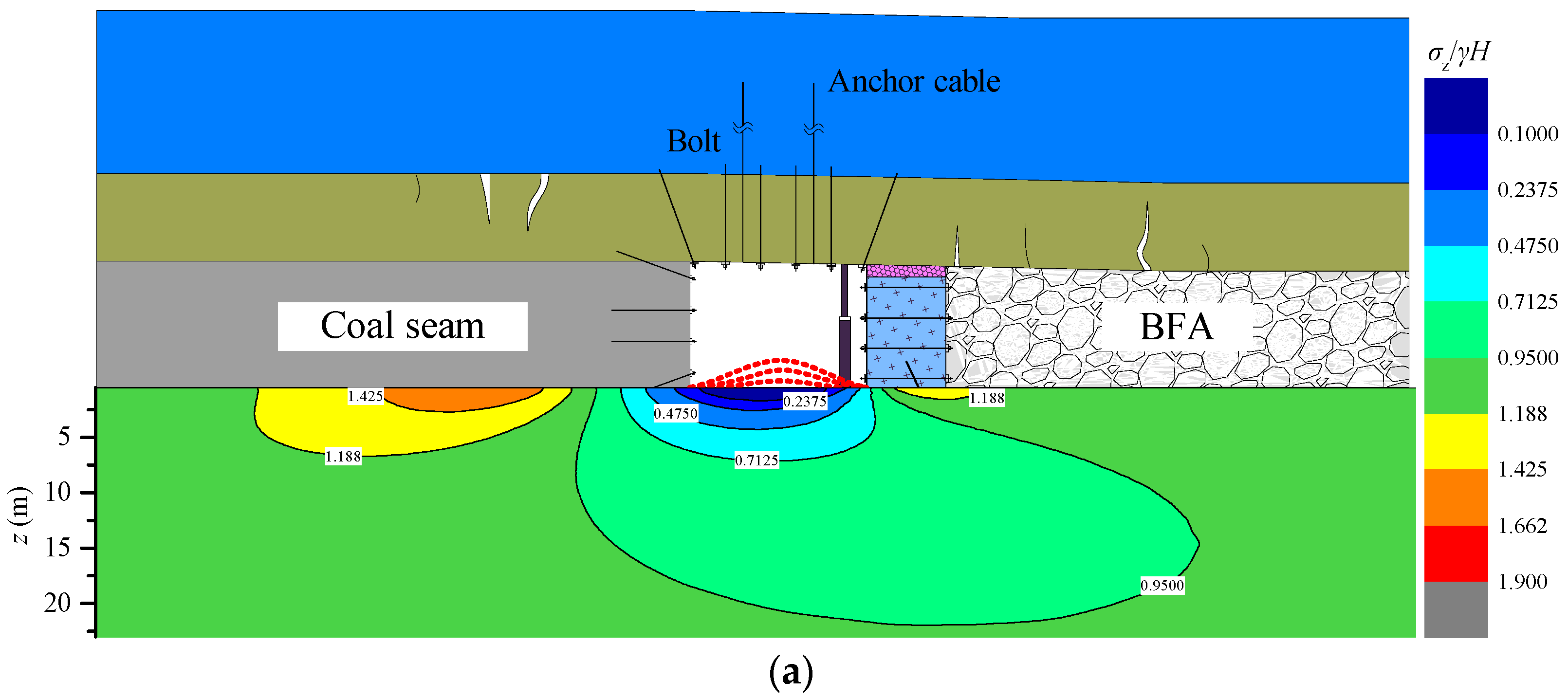

Figure 15.
Floor heave control technology of gob-backfilled GER. (a) Floor grouting; (b) Inverted arch pouring; and (c) Stress relief groove in the floor.
Figure 15.
Floor heave control technology of gob-backfilled GER. (a) Floor grouting; (b) Inverted arch pouring; and (c) Stress relief groove in the floor.
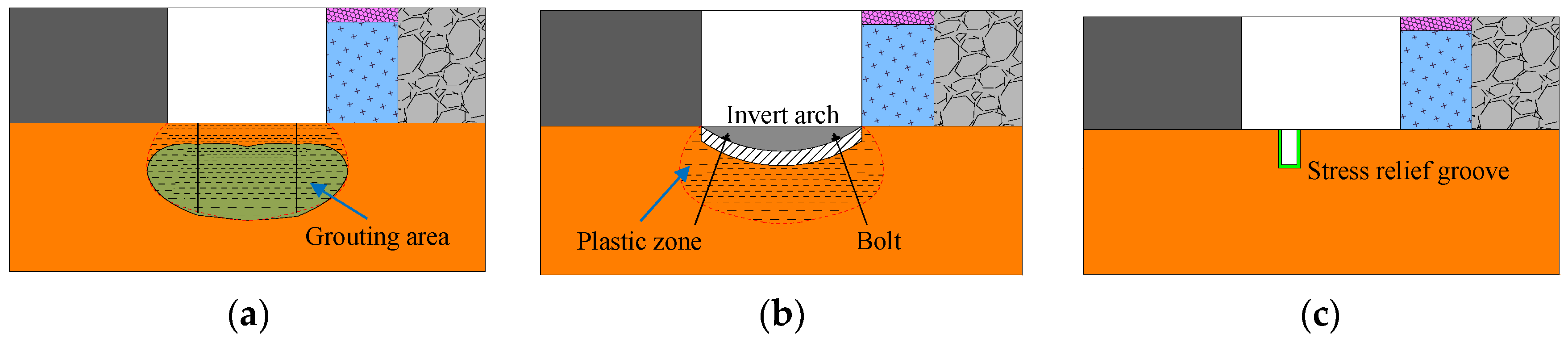
Figure 16.
Design of floor heave control scheme of gob-backfilled GER and field control effect. (a) Floor heave control scheme; and (b) Field control effect of floor heave.
Figure 16.
Design of floor heave control scheme of gob-backfilled GER and field control effect. (a) Floor heave control scheme; and (b) Field control effect of floor heave.


Table 1.
Parameters of vertical stress distribution in the roadside.
| L1/m | L3/m | L4/m | d/m | K | L1/m | |
|---|---|---|---|---|---|---|
| 2 | 4 | 8 | 4 | 1.53 | 1.3γH | 2 |
© 2017 by the authors. Licensee MDPI, Basel, Switzerland. This article is an open access article distributed under the terms and conditions of the Creative Commons Attribution (CC BY) license (http://creativecommons.org/licenses/by/4.0/).
Share and Cite
MDPI and ACS Style
Gong, P.; Ma, Z.; Ni, X.; Zhang, R.R. Floor Heave Mechanism of Gob-Side Entry Retaining with Fully-Mechanized Backfilling Mining. Energies 2017, 10, 2085. https://doi.org/10.3390/en10122085
AMA Style
Gong P, Ma Z, Ni X, Zhang RR. Floor Heave Mechanism of Gob-Side Entry Retaining with Fully-Mechanized Backfilling Mining. Energies. 2017; 10(12):2085. https://doi.org/10.3390/en10122085
Chicago/Turabian StyleGong, Peng, Zhanguo Ma, Xiaoyan Ni, and Ray Ruichong Zhang. 2017. "Floor Heave Mechanism of Gob-Side Entry Retaining with Fully-Mechanized Backfilling Mining" Energies 10, no. 12: 2085. https://doi.org/10.3390/en10122085
Note that from the first issue of 2016, this journal uses article numbers instead of page numbers. See further details here.