Combination of Compensations and Multi-Parameter Coil for Efficiency Optimization of Inductive Power Transfer System
by
 ,
,
Guozhen Hu
1,2, 
Junkun Zhang
1,3,*,
Junhua Wang
1,
Zhijian Fang
1,
Changsong Cai
1 and
Zhongzheng Lin
1 1
School of Electrical Engineering, Wuhan University, Wuhan 430072, China
2
School of Electrical and Electronic Information Engineering, Hubei Polytechnic University, Huangshi 435003, China
3
Institute of New Energy, Wuhan 430040, China
*
Author to whom correspondence should be addressed.
Energies 2017, 10(12), 2088; https://doi.org/10.3390/en10122088
Submission received: 5 December 2017
/
Revised: 5 December 2017
/
Accepted: 6 December 2017
/
Published: 8 December 2017
(This article belongs to the Special Issue Wireless Power Transfer and Energy Harvesting Technologies)
Abstract
:A loosely coupled inductive power transfer (IPT) system for industrial track applications has been researched in this paper. The IPT converter using primary Inductor-Capacitor-Inductor (LCL) network and secondary parallel-compensations is analyzed combined coil design for optimal operating efficiency. Accurate mathematical analytical model and expressions of self-inductance and mutual inductance are proposed to achieve coil parameters. Furthermore, the optimization process is performed combined with the proposed resonant compensations and coil parameters. The results are evaluated and discussed using finite element analysis (FEA). Finally, an experimental prototype is constructed to verify the proposed approach and the experimental results show that the optimization can be better applied to industrial track distributed IPT system.
1. Introduction
Inductive power transfer (IPT) is the process of transferring power without wired interconnects. With an extra degree of freedom on electrical isolation and the absence of mechanical contact between the power supply side and the load, the IPT system has the advantages of low maintenance cost, high reliability, and the ability to operate in rugged environment [1,2,3].
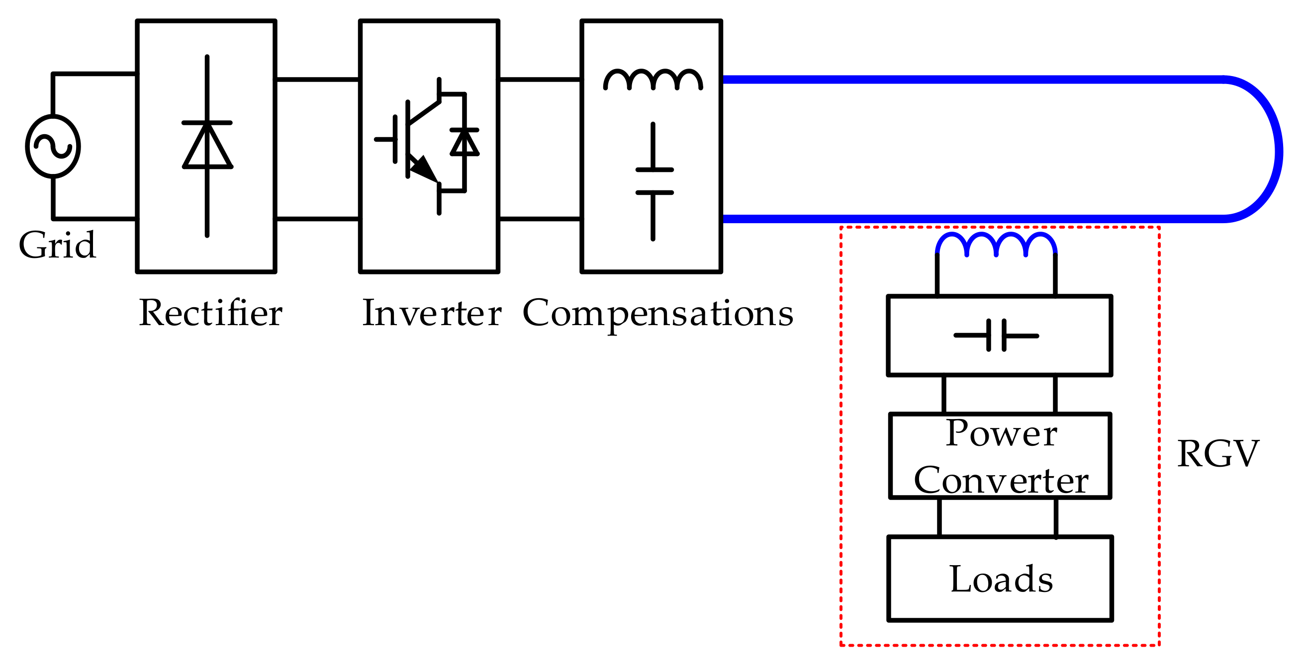
A typical distributed IPT system is presented in Figure 1, which has been used in automotive industry for materials handling applications [4,5,6]. The primary magnetic structure is an elongated track loop carrying an AC current. And one or more Rail Guide Vehicles (RGV) with pickup coils are powered as they drive on the track and this is called on-line dynamic powering.
On-line dynamic powering is a promising technology that can help promote the adoption in variety of industrial applications [7,8]. But this mode have reduced coupling and are not as efficient as stationary powering [9,10]. Therefore, appropriate circuit design and coil design can ensure the desirable power demands.
A number of IPT power supply have been developed in previous studies. An LCL fixed-frequency resonant topology has been proven to be suitable for supplying a steady-state track current [11,12,13,14]. And series- and parallel-compensations has been carried out to circumvent low power transfer [15,16,17,18]. However, these compensations are often studied under some isolated constraints for optimal system efficiency and less consideration of the effect of pickup coil parameters on the system.
Secondary pickup coil design is also an important factor for improving system efficiency. Recent studies have analyzed the magnetic field characteristics and power transmission effect of different shapes of pickup coils, such as round, rectangular, double D type [19,20,21,22]. In loosely coupled IPT system, self-inductance and mutual inductance are more important parameters for coil design. The mathematical method has been present in some applications, which both the primary transmitting coil and secondary receiving coil are charge pads with multiple windings [23,24,25]. Less mathematical analysis was carried out for distributed IPT systems shown in Figure 1. This paper attempts to propose a coil analytical model and accurate expressions of self-inductance and mutual inductance for optimizing the system efficiency.
In this paper, a detailed analysis is proposed for combination of compensation network and coil design to achieve an optimal operating efficiency. And accurate coil analytical model and expressions of self-inductance and mutual inductance for the system are present in details. Consequently, optimization results are given by theoretical analysis and finite element analysis. The remainder of the paper is organized as follows. Section 2 presents the principle of LCL fixed-frequency resonant topology of the IPT system. And the influencing factors on the output efficiency are analyzed in details. Section 3 presents an analytical approach for accurate computing the self-inductance and mutual inductance between the track and pickup coils. Section 4 presents analysis results of multi-parameter coupling coil and the results are evaluated and discussed using finite element analysis. Finally, Section 5 presents the experimental results.
2. Efficiency Influencing Factors of IPT System
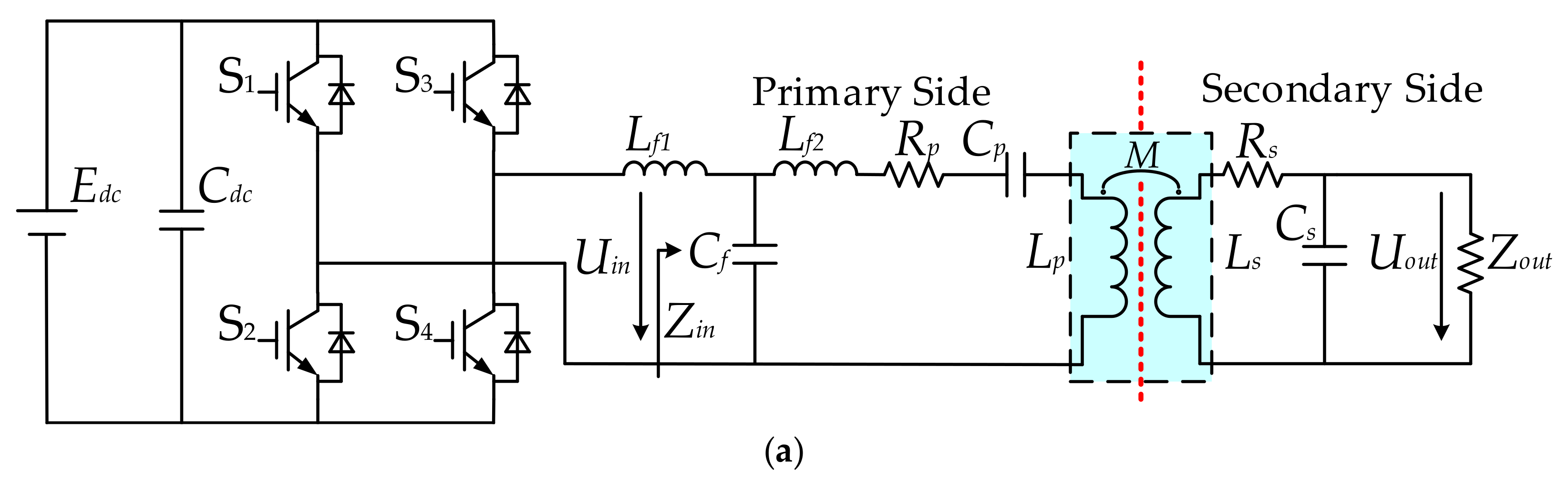
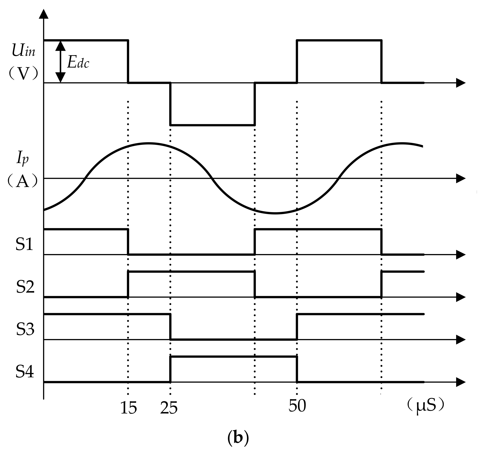
The topology of the IPT system is given in Figure 2. The phase-shifted pulse-width modulated full-bridge topology with Inductor-Capacitor-Inductor (LCL) network in Figure 2a is adopted at the primary side, and the LC parallel resonance circuit is adapted to at the secondary side. The switching signals, control signals, and electrical waveforms are shown in Figure 2b.
In the LCL resonant network, Lf1 is the inductance at the inverter side, Lf2 is the inductance at the track side, Cf is the resonant capacitance at the primary side. The parasitic resistances of the resonant components are assumed to be small and are therefore neglected. Lf1 and Cf are tuned for operating at the switching frequency ω of the system. When the DC bus voltage Edc keeps invariant, the track current Ip at the primary side is given by
Uin is the output voltage of the inverter bridge. From Equation (1), the track current IP at the primary side can keep constant, which is independent of load, and the inverter only supplies the real power required by the load and any losses in the resonant tank.
According to the resonance compensating characteristics of the IPT system, the resonance condition at the primary and secondary side of the IPT system can be obtained.
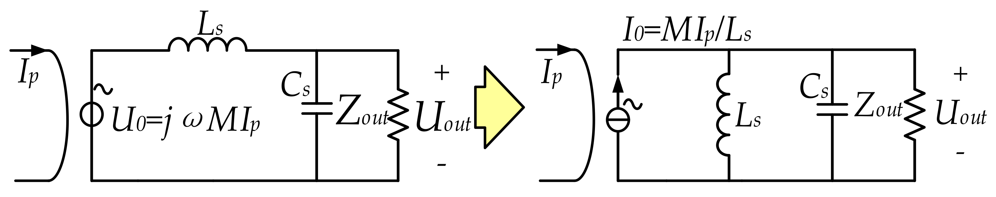
Figure 3 presents the equivalent circuit of the inductive pickup coil at the secondary side, where the LC parallel resonance circuit is adopted. For simplified analysis, the circuit can be equivalent by Thevenin and Norton’s Theorem. M is the mutual inductance between the primary track and secondary coil.
Considering that the couple self-inductance LS is larger than the internal resistance RS of the pickup coil, the current IS is given by
Zout is the equivalent load impedance. According to the impedance analysis and the circuit theory, the power output Pout of the IPT system can be obtained.
Furthermore, the output efficiency can also be given as follows.
RP is internal resistance of the track. When the quality factor of the parallel resonance at the secondary side is larger, RS can not be neglected. Therefore, the output efficiency can be shown in Equation (6).
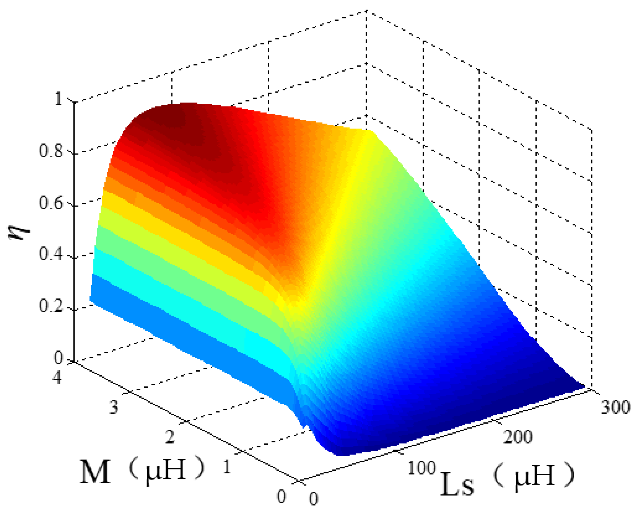
From Equation (6), the higher output efficiency η can be obtained when RP, RS are smaller in the system. Moreover, η is becoming higher with the increase of ω and M. However, the switching frequency is limited to 20–50 kHz, because ω is limited by the power grade and switching devices in medium or large frequency system.
Furthermore, in order to obtain the optimal output efficiency, Equation (6) is derivative and the optimization condition is given by.
It is clear that the optimal output efficiency η of the IPT system can be obtained only if Equation (7) can be established.
From Equations (6) and (7), the optimal output efficiency η is affected by M, LS and RS when other parameters of the IPT system at the primary side are fixed. And the output efficiency of the IPT system is shown in Figure 4.
M, LS and RS have a direct relation with coil design. Therefore, a proper analytical approach of coil design should be employed.
3. Accurate Computation of Coil Parameters
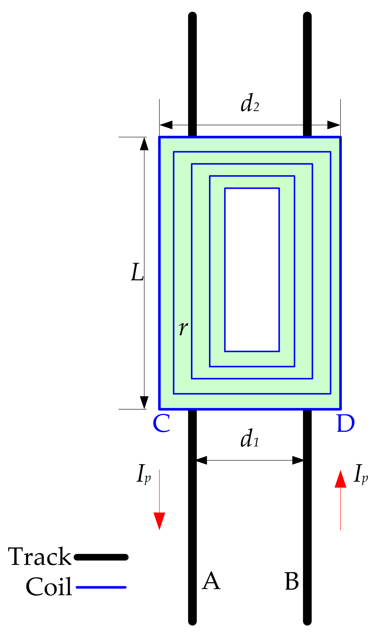
In this section, an analytical approach and mathematical expression is present for computing the self-inductance and mutual inductance between the track and pick-up coils. A rectangular plane coil model is shown in Figure 5 according to engineering requirements for RGV application.
3.1. Calculation of Self-Inductance
Figure 6 shows the equivalent plane diagram of the coil and the track. Magnetic flux density B(x,y) at any point of the rectangular coil can be given by applying Biot–Savart law.
The length, width and wire diameter of the coil is L, d2 and w respectively. Where the y-axis is in the direction of the track and the x-axis is perpendicular to the track direction.
When the current flows on one of the long side L of the rectangular coil, the magnetic flux φ11L in the rectangular region is given by
Similarly, when the current flows the width side d2 of the rectangular coil, the magnetic flux φ12d2 in the rectangular area is given by
So the total magnetic flux of rectangular coil can be obtained.
The winding gap of the coil is r. From Figure 4, the j-turn length is L − 2 (j − 1) r, and the width is d2 − 2 (j − 1) r. The track current IP flowing each turn is the same. Therefore, the self-inductance Ljj of the j-th coil can be calculated from the magnetic flux passing through the j-th turn, and the mutual inductance Ljk among the winding turns is calculated by the magnetic flux of the k-th turn, where Lkj = Ljk. Therefore, the mutual inductance between the j-th and k-th turns is given by
where , , .
When j = k, the inductance of the coil is the sum of self inductance and the inductance of the multi-turn winding. Therefore, the self-inductance LS of N turn rectangle coil can be expressed as:
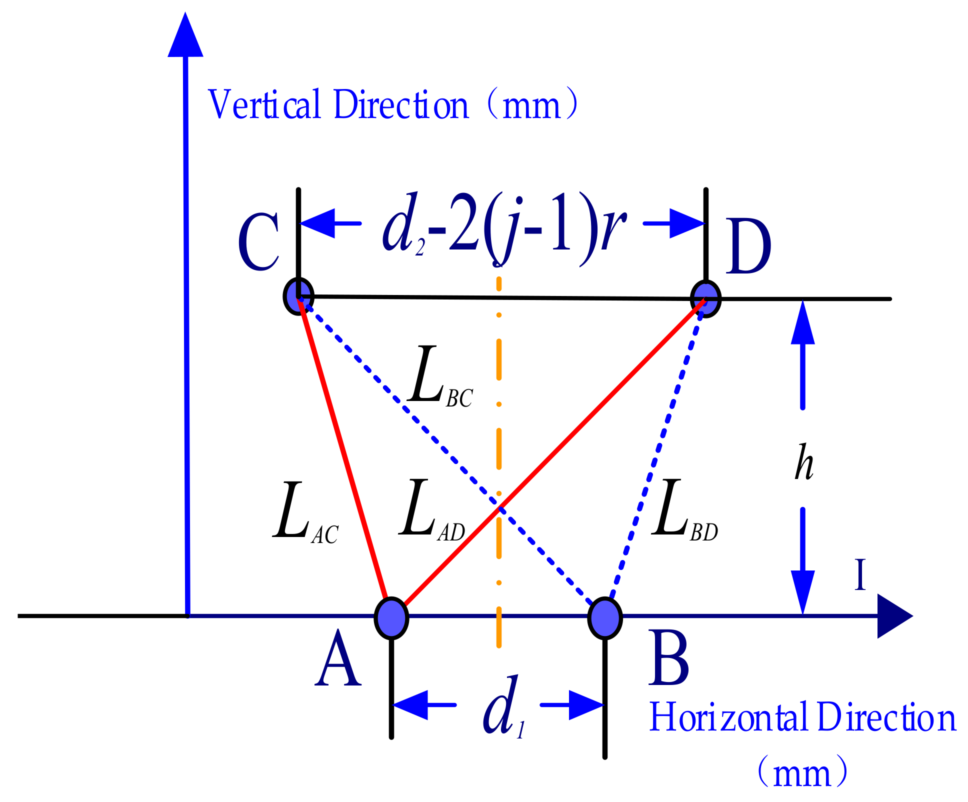
3.2. Accurate Computation of Mutual Inductance
As shown in Figure 4, the flux linkage of the N turn coil is the sum of the flux generated by the track. The vertical surface equivalent diagram between the track and the coil is shown in Figure 7. d1 is the track spacing. h is the distance between the coil and the track.
The magnetic flux produced by track A through the j-th coil area is given by
And the magnetic flux produced by track B through the j-th coil is given by
where .
The magnetic flux through the j-th turn is:
And the magnetic flux generated by track A and B on the N turn coil is:
Furthermore, the mutual inductance M between the track and the N-turn rectangular coil is:
3.3. Internal Resistance Calculation of Track and Coil
The internal resistance RS of coil can be calculated as follows:
ρcu is the electrical resistivity and SS is cross-sectional area of the coil. To improve the output efficiency, RS should be as small as possible.
4. Efficiency Optimization Analysis of the IPT System
From Section 3, it is known that mutual inductance M and self-inductance Ls are related to the geometrical structure, spatial position, turns and wingding gap of the coil. The Equation (6) shows that the efficiency is not only related to the design of coil parameters, but also the circuit structure and resonance compensations. In this section, the efficiency optimization is present based on the proposed IPT topology.
4.1. Optimization Design Process
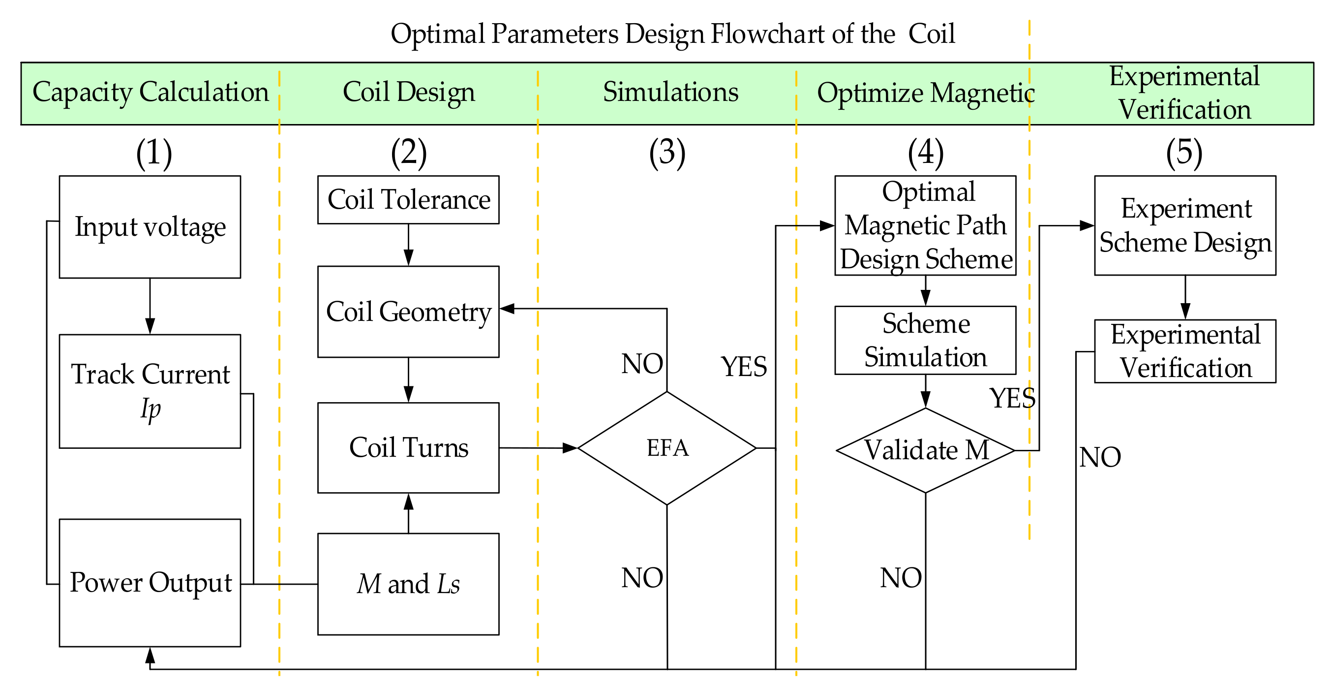
The design flowchart of the system is presented in Figure 8.
Firstly, optimization of the IPT system needs to consider the power requirements for RGV application, which determines the topology and compensations. And the coil design mainly considers the influence of coil tolerance, geometry and turns on mutual inductance and self-inductance. Furthermore the coil parameters are verified through finite element analysis for optimum efficiency. When the optimization of the coil is completed, the mutual inductance of the coil can be further improved through displacement the magnetic strip reasonably. Whether the above design meets the requirements also needs to be verified by experiments.
4.2. Optimization Analysis of Coil Parameters
To simplify the analytical calculations and to reduce the computation time, some assumptions are made based on industrial field, such as coil size and track spacing must meet the installation of RGV application. The parameters of IPT system are shown in Table 1.
Combined with self-inductance calculation Equation (13) and mutual inductance calculation Equation (18), the effects of the winding gap r, the turns N to the self-inductance LS and mutual inductance M are shown in Figure 9.
Furthermore, the relationship between the turns, winding gap and the output efficiency of the system is shown in Figure 10.
From the results in Figure 10, the optimum efficiency of the system is 81.2%. And the optimized coil parameters can be obtained as N = 14, r = 7 mm, Ls = 61.2 μH and M = 1.91 μH respectively.
The output efficiency of long-track-loop structure of on-line dynamic powering IPT system is lower than stationary system. This is because the inductance of the long track is so large that the switching frequency is usually limited to 20–50 kHz. Also the quality factor of the long loop is therefore lower than the stationary system for the effect of track internal resistance. However, flexible routing path makes the dynamic powering system suitable for industrial RGV applications.
At the same time, the output efficiency is also affected by vertical and horizontal migration. Output efficiency with misalignment is shown in Figure 11. Apparently the output efficiency decreases with the increase of migration.
4.3. Finite Element Analysis (FEA)
The 3D Maxwell finite element software is used to verify and analyze the coil parameters, so as to verify whether the coil parameters meet the optimum out efficiency.
FEA simulation model of coil is shown in Figure 12.
The result of FEA is shown in Figure 13. It can be seen that the optimum output efficiency is basically consistent with the theoretical optimization analysis.
Proper placement of the magnetic strip over the coil can shorten the magnetic circuit, reducing the edge of the magnetic flux, thereby enhancing the mutual inductance between the track and the coil. The choices of magnetic stripe mainly consider the magnetization curve, magnetic loss, geometric size and so on.
FEA simulation model of coil with magnetic strip is shown in Figure 14. Ferrite PC40 magnetic strips are closed to the coil surface. The size of the magnetic stripe is 90 mm × 5 mm × 15 mm.
After adding the magnetic stripe, the value of M is 2.82 μH and the system optimum output efficiency can be improved as 85.6%.
Finally, the magnetic field radiation also can be evaluated with Finite Element Analysis (FEA) simulation results. The design satisfies the relevant standard of the International Commission on Non-Ionizing Radiation Protection (ICNIRP) magnetic field radiation under the actual working condition.
The results with placement of the magnetic strip are shown in Figure 15.
5. Experimental Results
A prototype is constructed to verify the proposed system and the experimental parameters are shown in Table 1.
IPT power supply and primary track with a RGV are shown in Figure 16.
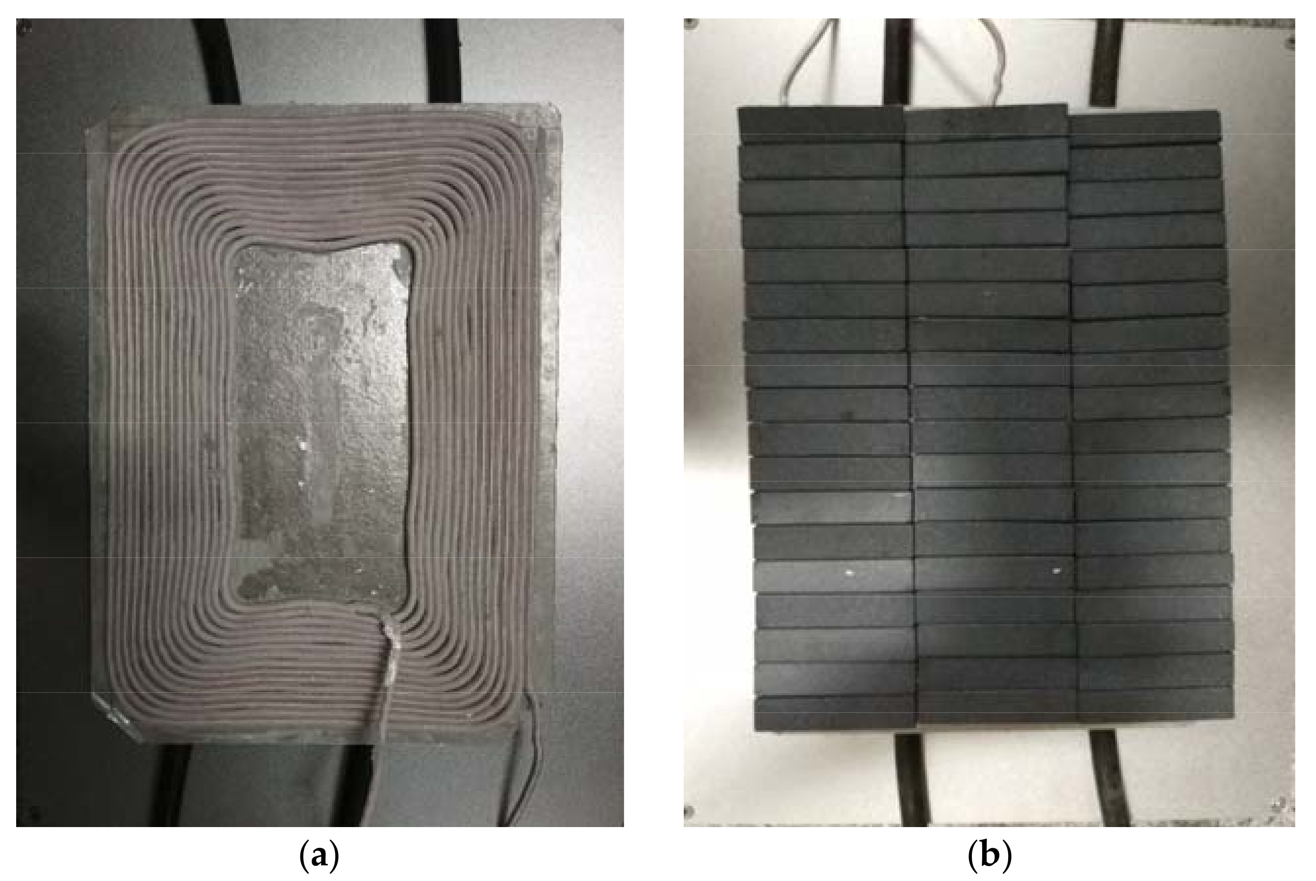
And the structure and dimension of the pickup coil is shown in Figure 17.
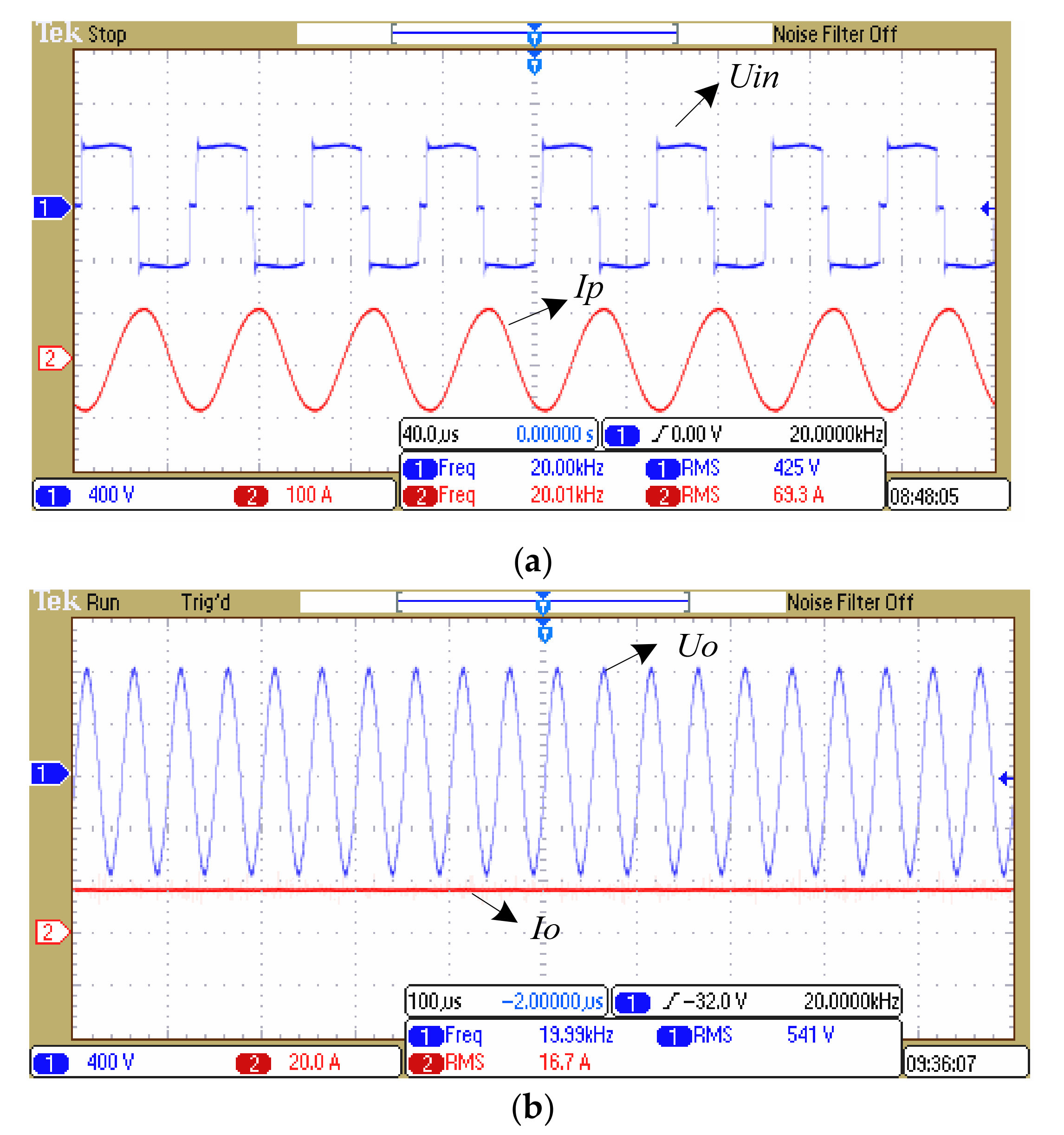
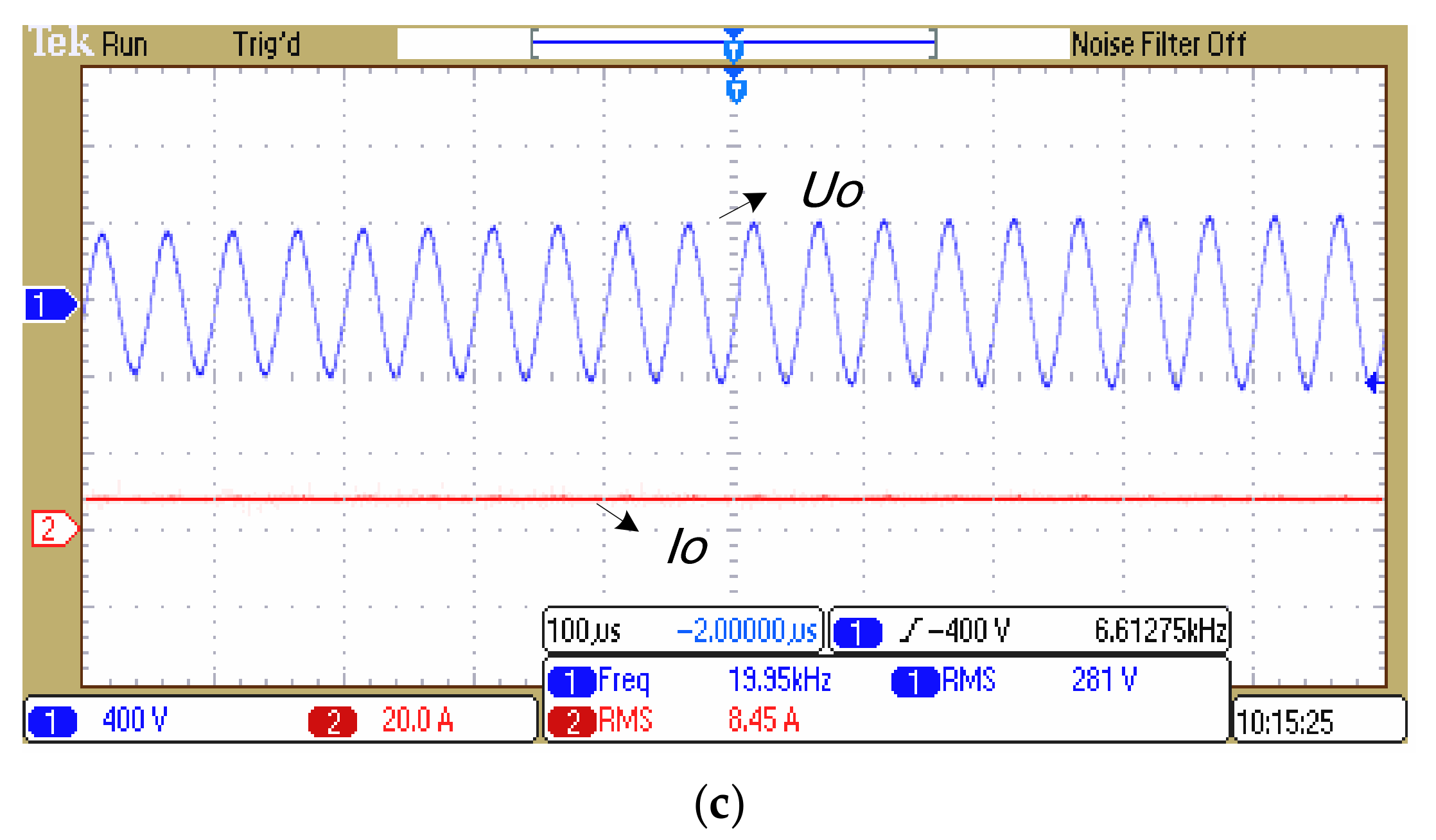
The experimental results of the IPT system are shown in Figure 18. In Figure 18a CH1 is the waveform of the voltage of the inverter bridge arms, and CH2 is the waveform of the track current IP, which is an AC 20 kHz high-frequency sine wave. Similarly, resonant waveform at secondary side is presented in Figure 18b,c, where CH1 is the waveform of the LC resonant voltage at the secondary side, and CH2 is the waveform of the load current at half and full loads. A post-stage power converter is able to regulate the output AC voltage to a desired DC value. The output voltage of pickup is 24 VDC for RGV applications.
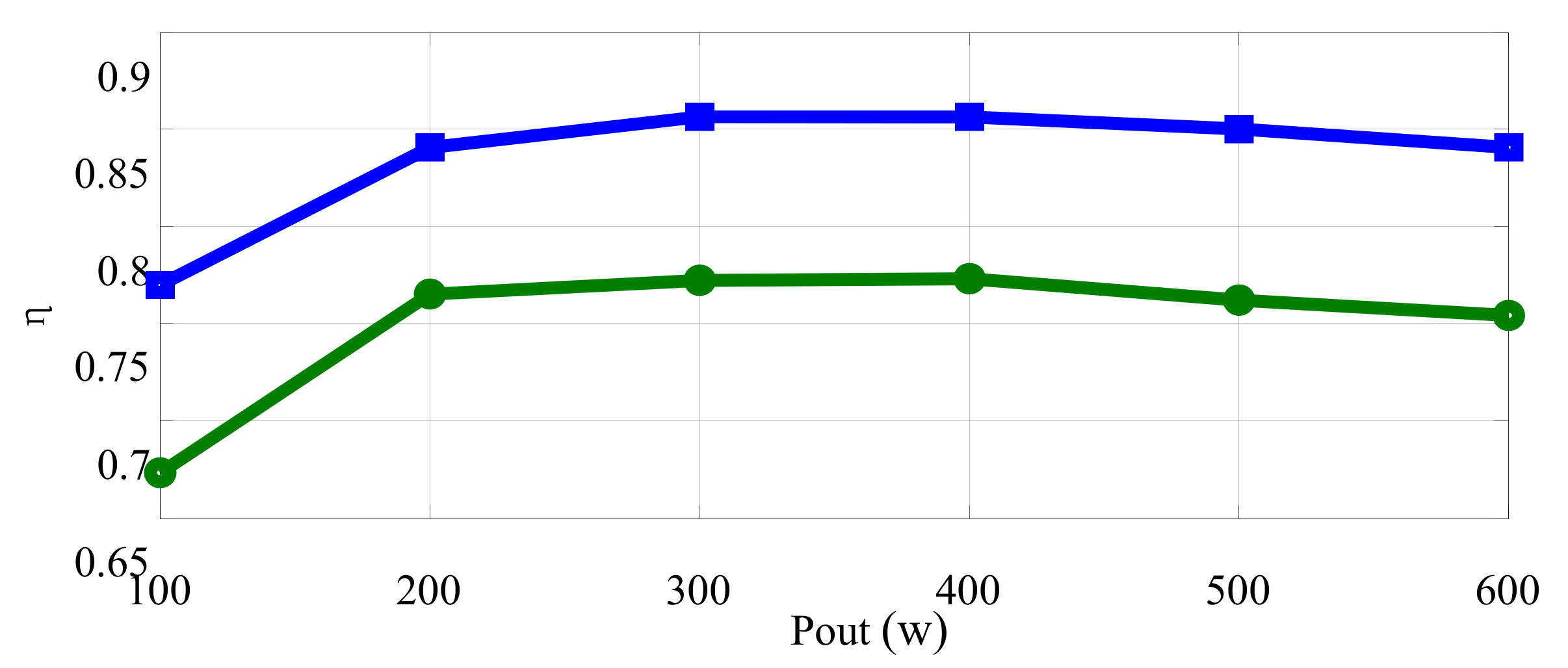
Comparison of the output efficiency under different loads with the theoretical efficiency is shown in Figure 19. It is clear that the efficiency is slightly lower than the theoretical efficiency because of the effects of the circuit losses, the switching losses and the coil misalignment.
6. Conclusions
In this paper, the multi-parameter optimization of an IPT system for industrial RGV application was presented. The optimal output efficiency is mainly affected by self-inductance and mutual inductance between primary track and secondary pick-up coil. Therefore, an accurate analytical method based on Biot–Savart law has been presented for estimating self-inductance and mutual inductance between the track and the coil. Furthermore, optimization for coil parameters has been present through analytical calculation and FEA simulation. The experimental results show a good agreement with analytical and FEA results.
Acknowledgments
The authors would like to thank financial supports provided by the National Natural Science Foundation of China (51507114), China Postdoctoral Science Foundation (168154) and Natural Science Foundation of Hubei Province (2016CFB516, D20164501).
Author Contributions
Guozhen Hu has contributed to the theoretical approaches and preparing the article; Junkun Zhang contributed to the simulation and experiment. Junhua Wang has contributed to the theoretical approaches; Zhijian Fang has contributed to language modification. Changsong Cai has contributed to thesis revision. Zhongzheng Lin has contributed to data processing.
Conflicts of Interest
The authors declare no conflict of interest.
References
- Kafeel, A.K.; Muhammad, A.; Saad, M. Inductively coupled power transfer for electric vehicle charging—A review. Renew. Sustain. Energy Rev. 2015, 47, 462–475. [Google Scholar]
- Lu, F.; Zhang, H.; Hofmann, H.; Mi, C.C. A Dynamic Charging System with Reduced Output Power Pulsation for Electric Vehicles. IEEE Trans. Ind. Electron. 2016, 63, 6580–6590. [Google Scholar] [CrossRef]
- Zhang, W.; Wong, S.C.; Tse, C.K.; Chen, Q. Analysis and Comparison of Secondary Series- and Parallel-Compensated Inductive Power Transfer Systems Operating for Optimal Efficiency and Load-Independent Voltage-Transfer Ratio. IEEE Trans. Power Electron. 2014, 29, 2979–2990. [Google Scholar] [CrossRef]
- James, J.E.; Robertson, D.J.; Covic, G.A. Improved AC Pickups for IPT Systems. IEEE Trans. Power Electron. 2014, 29, 6361–6374. [Google Scholar] [CrossRef]
- Li, H.L.; Hu, A.P.; Covic, G.A. A Direct AC–AC Converter for Inductive Power-Transfer Systems. IEEE Trans. Power Electron. 2012, 27, 661–665. [Google Scholar] [CrossRef]
- Zaheer, A.; Covic, A.G.; Kacprzak, D. A Bipolar Pad in a 10-kHz 300-W Distributed IPT System for AGV Applications. IEEE Trans. Ind. Electron. 2014, 61, 3288–3301. [Google Scholar] [CrossRef]
- Shin, J.; Shin, S.; Kim, Y.; Ahn, S.; Lee, S. Design and implementation of shaped magnetic-resonance-based wireless power transfer system for roadway-powered moving electric vehicles. IEEE Trans. Ind. Electron. 2014, 61, 1179–1192. [Google Scholar] [CrossRef]
- Su, Y.C.; Beom, W.G.; Seog, Y.J.; Chun, T.R. Advances in Wireless Power Transfer Systems for Roadway-Powered Electric Vehicles. IEEE J. Emerg. Sel. Top. Power Electron. 2015, 3, 18–36. [Google Scholar]
- Budhia, M.; Boys, J.T.; Covic, G.A.; Huang, C.Y. Development of a single-sided flux magnetic coupler for electric vehicle IPT charging systems. IEEE Trans. Ind. Electron. 2013, 60, 318–328. [Google Scholar] [CrossRef]
- Valtchev, S.; Borges, B.; Brandisky, K.; Klaassens, J.B. Resonant contactless energy transfer with improved efficiency. IEEE Trans. Power Electron. 2009, 24, 685–699. [Google Scholar] [CrossRef]
- Keeling, N.; Covic, A.G.; Hao, F.; George, L.; Boys, J.T. Variable Tuning in LCL Compensated Contactless Power Transfer Pickups. In Proceedings of the Energy Conversion Congress & Exposition, San Jose, CA, USA, 20–24 September 2009; pp. 1826–1832. [Google Scholar]
- Hao, H.; Covic, G.A.; Boys, J.T. An Approximate Dynamic Model of LCL- T-Based Inductive Power Transfer Power Supplies. IEEE Trans. Power Electron. 2014, 29, 5554–5567. [Google Scholar] [CrossRef]
- Wang, C.S.; Covic, G.A.; Stielau, O.H. Investigating an LCL load resonant inverter for inductive power transfer applications. IEEE Trans. Power Electron. 2004, 19, 995–1002. [Google Scholar] [CrossRef]
- Borage, M.; Tiwari, S.; Kotaiah, S. LCL-T Resonant Converter with Clamp Diodes: A Novel Constant-Current Power Supply with Inherent Constant-Voltage Limit. IEEE Trans. Ind. Electron. 2007, 54, 741–746. [Google Scholar] [CrossRef]
- Pantic, Z.; Bai, S.; Lukic, M.S. ZCS LCC-Compensated Resonant Inverter forInductive-Power-Transfer Application. IEEE Trans. Ind. Electron. 2011, 58, 3500–3510. [Google Scholar] [CrossRef]
- Cimen, S.G.; Pfannkuchen, A.; Schmuelling, B. Compensation Considerations for Bidirectional Inductive Charging Systems of Electric Vehicles with Coil Positioning Flexibility. IEEE Trans. Magn. 2016, 52, 1–4. [Google Scholar] [CrossRef]
- Feng, H.; Cai, T.; Duan, S.; Zhao, J.; Zhang, X. An LCC Compensated Resonant Converter Optimized for Robust Reaction to Large Coupling Variation in Dynamic Wireless Power Transfer. IEEE Trans. Ind. Electron. 2016, 63, 6591–6601. [Google Scholar] [CrossRef]
- Guidi, G.; Suul, J.A. Minimizing Converter Requirements of Inductive Power Transfer Systems with Constant Voltage Load and Variable Coupling Conditions. IEEE Trans. Ind. Electron. 2016, 63, 6835–6844. [Google Scholar] [CrossRef]
- Bosshard, R.; Iruretagoyena, U.; Kolar, J.W. Comprehensive Evaluation of Rectangular and Double-D Coil Geometry for 50 kW/85 kHz IPT System. IEEE J. Emerg. Sel. Top. Power Electron. 2016, 4, 1406–1415. [Google Scholar] [CrossRef]
- Charalampos, A.S.; Zaspalis, V. Impact of ferrite shield properties on the low-power Inductive Power Transfer. IEEE Trans. Magn. 2016, 52, 1–5. [Google Scholar]
- Boys, J.T.; Elliott, G.A.J.; Covic, G.A. An Appropriate Magnetic Coupling Co-Efficient for the Design and Comparison of ICPT Pickups. IEEE Trans. Power Electron. 2007, 22, 333–335. [Google Scholar] [CrossRef]
- Budhi, B.; Covic, G.A.; Boys, J.T. Design and Optimization of Circular Magnetic Structures for Lumped Inductive Power Transfer Systems. IEEE Trans. Power Electron. 2011, 26, 3096–3108. [Google Scholar] [CrossRef]
- Joy, E.R.; Dalal, A.; Kumar, P. Accurate Computation of Mutual Inductance of Two Air Core Square Coils with Lateral and Angular Misalignments in a Flat Planar Surface. IEEE Trans. Magn. 2014, 50, 1–9. [Google Scholar] [CrossRef]
- Fotopoulou, K.; Flynn, B.W. Wireless Power Transfer in Loosely Coupled Links: Coil Misalignment Model. IEEE Trans. Magn. 2011, 47, 416–430. [Google Scholar] [CrossRef]
- Prasanth, V.; Bauer, P. Distributed IPT Systems for Dynamic Powering: Misalignment Analysis. IEEE Trans. Ind. Electron. 2014, 61, 6013–6201. [Google Scholar] [CrossRef]
Figure 1.
Industrial Rail Guide Vehicles (RGV) inductive power transfer system.

Figure 2.
Topology of the inductive power transfer (IPT) system. (a) Power converter schematic of IPT system; (b) Switching signals, control signals, and electrical waveforms.
Figure 2.
Topology of the inductive power transfer (IPT) system. (a) Power converter schematic of IPT system; (b) Switching signals, control signals, and electrical waveforms.


Figure 3.
The equivalent circuit model at the secondary side.

Figure 4.
Output efficiency with M and LS.

Figure 5.
Magnetic field coupling model for RGV application.

Figure 6.
Equivalent diagram of the coil and track.

Figure 7.
Vertical equivalent diagram between the track and the coil.

Figure 8.
Design flowchart of the IPT system.

Figure 9.
Calculated value of LS and M with variable N and r. (a) N-r-LS; (b) N-r-M.

Figure 10.
Output efficiency with variable N and r.
Figure 11.
Output efficiency with misalignment.

Figure 12.
Finite element simulation model of coil.
Figure 13.
Results of finite element simulation.

Figure 14.
Model with placement of the magnetic strip.
Figure 15.
Finite Element Analysis (FEA) simulations with placement of the magnetic strip. (a) plan; (b) axial.
Figure 15.
Finite Element Analysis (FEA) simulations with placement of the magnetic strip. (a) plan; (b) axial.

Figure 16.
Experimental platform of IPT system: (a) experimental panorama of the platform; (b) the converter of the primary side.
Figure 16.
Experimental platform of IPT system: (a) experimental panorama of the platform; (b) the converter of the primary side.
Figure 17.
Pickup coil physical map. (a) couplings coil; (b) couplings coil with magnetic strips.

Figure 18.
Experimental results of IPT system. (a) Waveform at the primary side (CH1:400 V/div, CH2:100 A/div, Time: 40 μs/s); (b) Waveform at secondary side at full load (CH1:400 V/div, CH2:20 A/div, Time: 100 μs/s); (c) Waveform at secondary side at half load (CH1:400 V/div, CH2:20 A/div, Time: 100 μs/s).


Figure 19.
Output efficiency under variable loads.


Table 1.
Experimental parameters of IPT system.
| Parameters | Values |
|---|---|
| Switching Frequency f | 20 kHz |
| Inductance Lf1 = Lf2 | 80 μH |
| Resonant Capacitance Cf | 0.5 μF |
| Self-inductance LP | 5 μH |
| Compensation Capacitance CP | 8 μF |
| Track Internal Resistance RP | 0.022 Ω |
| Inductive Coil Internal Resistance RS | 0.045 Ω |
| Output Power of Pickup | 400 W |
| Output Voltage of Pickup | 24 VDC |
© 2017 by the authors. Licensee MDPI, Basel, Switzerland. This article is an open access article distributed under the terms and conditions of the Creative Commons Attribution (CC BY) license (http://creativecommons.org/licenses/by/4.0/).
Share and Cite
MDPI and ACS Style
Hu, G.; Zhang, J.; Wang, J.; Fang, Z.; Cai, C.; Lin, Z. Combination of Compensations and Multi-Parameter Coil for Efficiency Optimization of Inductive Power Transfer System. Energies 2017, 10, 2088. https://doi.org/10.3390/en10122088
AMA Style
Hu G, Zhang J, Wang J, Fang Z, Cai C, Lin Z. Combination of Compensations and Multi-Parameter Coil for Efficiency Optimization of Inductive Power Transfer System. Energies. 2017; 10(12):2088. https://doi.org/10.3390/en10122088
Chicago/Turabian StyleHu, Guozhen, Junkun Zhang, Junhua Wang, Zhijian Fang, Changsong Cai, and Zhongzheng Lin. 2017. "Combination of Compensations and Multi-Parameter Coil for Efficiency Optimization of Inductive Power Transfer System" Energies 10, no. 12: 2088. https://doi.org/10.3390/en10122088
Note that from the first issue of 2016, this journal uses article numbers instead of page numbers. See further details here.