1. Introduction
In recent years, interior permanent-magnet synchronous motors (IPMSMs) have emerged as superior solutions for use in high-performance drive applications, owing to their advantageous features such as high efficiency, high power density, robust and wide-speed operation, and low noise [
1,
2,
3]. The benefits of using the IPMSM drives have been established well in [
4,
5].
In order to make good use of the aforementioned advantageous features of an IPMSM, and to achieve fast and accurate responses, it is very important to obtain the exact
d- and
q-axis reactance parameters of the IPMSM and to use them to estimate the applied torque with high accuracy [
6]. Such accurate torque estimation is essential to produce the desired torque. In the electric-vehicle industry, it is believed that the torque tracking errors should be less than 5% in order to provide torque with tolerable precision with respect to the accelerator pedal position [
7]. Widely used ideal models based on the orthogonal or decoupled
d- and
q-axes may be different from an actual system with cross-coupling effects and various parameter variations, as the operation of the IPMSM is strongly affected by the rotor magnetic saliency [
8], core saturation [
9], temperature [
10], and armature reaction effects [
11]. For this reason, the torque equation derived from an ideal model does not hold when applied in real cases [
12,
13,
14]. For accurate torque estimation, a more sophisticated model is required, which should account for the cross-coupling and parameter variations.
Two representative approaches have been used to overcome the aforementioned inaccurate torque estimation issues arising from the inherent physical limitations: a lookup table method and a direct torque control (DTC) scheme. Lookup tables, as widely used methods for estimating the torque of an IPMSM, have been employed to tabulate the optimal current commands computed a priori with respect to various operation conditions such as the DC link voltage, rotor speed, magnet temperature, etc. [
15,
16]. The current commands corresponding to the desired torque references are drawn from these tables based on the operation conditions. Constructing such lookup tables requires time and effort, as the same experiments should be repeated under different conditions. Furthermore, minor parameter variations from aging effects may not be reflected immediately on an already-determined lookup table. In order to reduce the size of the tables, analytical approaches have been trying to solve the torque equations with some voltage constraints, at the expense of real-time computation [
1,
17]. However, since these analytical approaches are strongly dependent on mathematical models, they tend to be less robust and more sensitive to uncertainties in situations of unexpected phenomena, which are not reflected in the models. The DTC scheme for IPMSM drives, which is another approach widely used to overcome the inaccurate torque estimation, has been explored since the 1990s [
18,
19]. DTC does not require an accurate model or parameters, except for the armature resistances. However, DTC exhibits problems such as unfixed switching frequency and large torque and stator flux ripples due to less dependence on system parameters. These drawbacks may result in reduced system efficiency and a short life span [
20]. In addition to the lookup table method and the DTC approach, the estimation of some parameters of IPMSMs have been attempted by using flux observers [
21,
22], by setting other parameters to their nominal [
23,
24] or measured [
25,
26] values, or by injecting perturbation signals [
27,
28,
29] and DC offset voltages [
30]. However, these existing estimation schemes often demonstrate mismatches between the nominal parameter values and the actual ones, as nominal models are used for estimation or unmodelled uncertainties are not considered. Especially, machine parameters can vary with the injected signals; this is difficult to describe in a mathematical fashion, and, as a result, often remains unmodelled. To the best of the authors’ knowledge, there has been no report of a real-time adaptive torque estimation algorithm that deals with a variety of uncertainties including cross-coupling effects and parameter variations, and that provides a more accurate torque equation. It would be very useful to develop such an adaptive torque estimation algorithm for IPMSMs.
In this paper, we present a new adaptive torque estimation algorithm for an IPMSM with cross-coupling and time-varying d- and q-axis reactance parameters. It is observed through experiments that the inductances are influenced by the magnitudes of both the corresponding current and the orthogonal current, and have their own nonlinearities and cross-coupling effects between the d- and q-axis components. Such nonlinear interactive inductances motivated us to introduce equivalent mutual inductances. All cross-coupling, time-varying, or uncertain terms that are not present in the nominal flux equations are placed into two equivalent mutual inductances described using the so-called equivalent d- and q-axis back electromotive forces (EMFs). The proposed algorithm estimates the equivalent d- and q-axis back EMFs in a recursive and stability-guaranteed way, in order to compute the equivalent mutual inductances between the d- and q-axes, and provides a more accurate and adaptive torque equation by adding the correction terms obtained from the computed equivalent mutual inductances. It is shown through simulations and experiments that the proposed torque estimation algorithm greatly reduces the torque estimation errors by capturing and compensating for the cross-coupling effects and parameter variations due to the changes in operating conditions.
The rest of this paper is organized as follows:
Section 2 describes a torque equation derived from a more elaborate model of an IPMSM. In
Section 3, the torque estimation algorithm is proposed to obtain the equivalent mutual inductance and finally produce an accurate torque equation. The performance of the proposed torque estimation algorithm is illustrated through simulations and experiments in
Section 4 and
Section 5, respectively. Finally, the proposed work is summarized and the conclusions are presented in
Section 6.
2. Real IPMSM Model and Its Corresponding Torque Equation
A precise model of the IPMSM is very important for high-performance vector-controlled servo drive systems. However, for simplicity, the IPMSM is often represented in terms of an ideal model based on the following assumptions:
The three-phase stator windings are symmetrical.
The slot effect is neglected and the back EMF is exactly sinusoidal.
Saturation, eddy currents, and hysteresis losses are neglected.
No damping exists in the rotor.
With these assumptions, the flux equations of the IPMSM in the synchronous reference frame are given by
where
and
are the
d- and
q-axis stator currents,
and
are the
d- and
q-axis stator inductances,
and
are the
d- and
q-axis stator magnetic fluxes, and
is the rotor flux. The electrical torque
based on the ideal model (1) and (2) is expressed as
where
P is the number of poles.
As seen in Equations (1) and (2), the ideal model assumes that the d- and q-axis stator inductances and are constant, and hence, independent of any currents, which is not the case in reality. Considering the core saturation effect and the spatial unbalance of fluxes, the d- and q-axis stator inductances are the functions of the d- and q-axis currents, and, furthermore, the cross-coupling phenomena cannot be neglected. Therefore, such current-dependent inductances and the mutual interactions between the d- and q-axes should be reflected for accurate torque estimation. In other words, it is necessary to modify the IPMSM model in Equations (1) and (2) and the corresponding torque Equation (3) into more realistic versions.
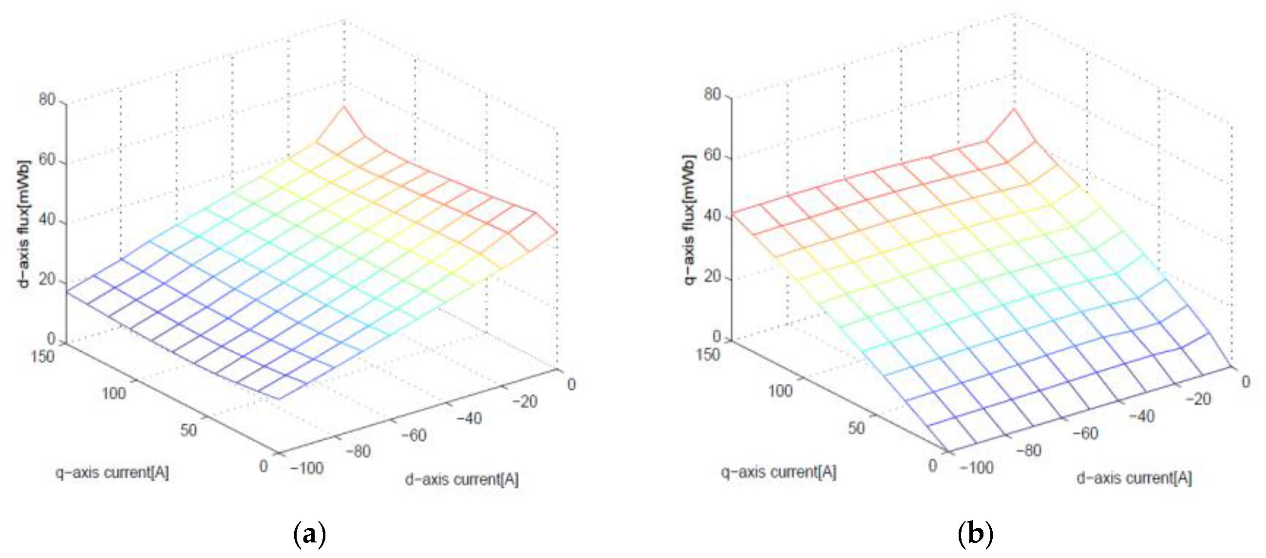
The coupling effect is illustrated through an experiment, which is shown in
Figure 1. The
d–
q axis output voltages were obtained by changing the
d–
q axis currents, while keeping the motor speed constant at the rated speed. The value of the flux for the
d–q current was calculated from the motor voltages and currents in the steady state. It is observed that the
d-axis flux is affected by the
q-axis current and the
q-axis flux by the
d-axis current. The ideal model (1) and (2) does not reflect such coupling. By using inductances varied by the
d- and
q-axis currents, and adding supplementary terms for reflecting the coupling effects, the ideal IPMSM model (1) and (2) can be rewritten as
where
and
are the mutual inductances of the
d- and
q-axis windings with respect to the
q- and
d-axis currents, respectively. Furthermore, considering the uncertainties of the inductances and the rotor flux yields:
where
,
,
,
, and
are constant nominal values and their variations are denoted by
,
, , and
. Rearranging the terms in Equations (6) and (7), we obtain
where
and
are given by
and are called equivalent mutual inductances, in this paper. It is noted that the two mutual inductances—
and
—are the functions of the
d- and
q-axis currents and inductance uncertainties. For simple notations,
and
will be used without arguments throughout this paper. Considering the mutual inductances and uncertainties, or substituting the fluxes (8) and (9) into the torque Equation (3), we have
It is observed from the comparison with Equation (3) that the torque components arising from the coupling effect and inductance variations are added in the third and fourth terms of Equation (12). Therefore, for more accurate torque estimation, the third and fourth terms in Equation (12) should be considered. In the following section, the estimation of
and
will be discussed.
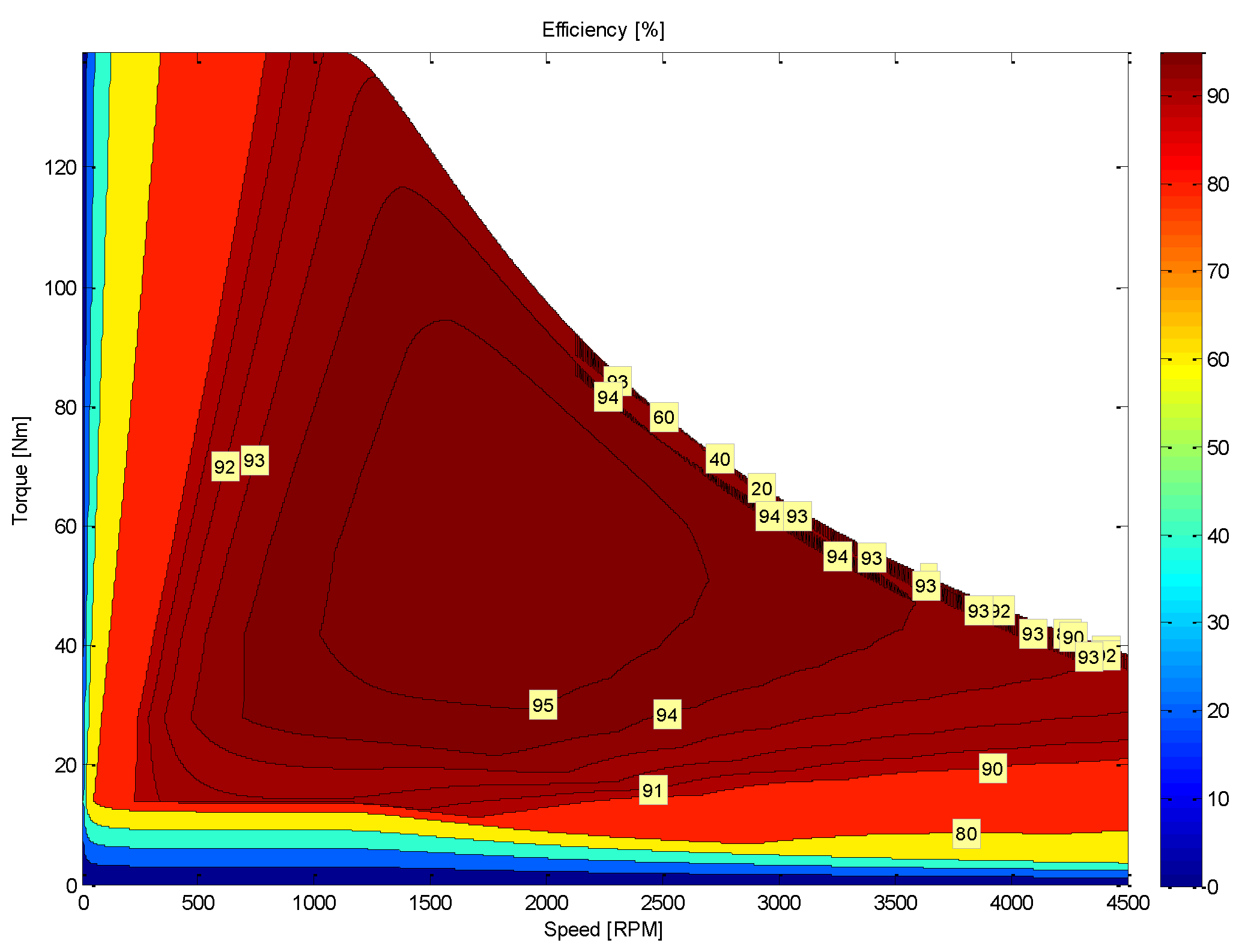
Figure 2 shows the efficiency map of the IPMSM at various operating points. It is calculated based on the above assumptions in which the core loss is not taken into account.
3. Algorithm for Estimating Mutual Inductances
In order to estimate
and
in Equations (10) and (11), we shall exploit the following voltage equations in the rotating
d–
q frame:
where
and
are the stator voltages,
is the stator resistance,
and
are the
d- and
q-axis stator magnetic fluxes, and
is the electrical rotor speed. Substituting Equations (8) and (9) into Equations (13) and (14), and using the matrix-vector form, we can write Equations (13) and (14) in a compact manner as follows:
where
denotes a differential operator. Representing the voltage Equations (15) in a simple form without the
d–
q axis coupling effects, we have
where
and
are given by
and are called the equivalent
d- and
q-axis back EMFs.
It is noted that all nonlinear, time-varying, or uncertain terms not present in the nominal stator voltage equations are included into the equivalent back EMFs and in Equations (17)–(18). The voltage equations in (16) have the same form as the nominal stator voltage Equations (13) and (14) only if the equivalent back EMFs are replaced with , and the mutual inductances and are set to zero.
From Equations (17) and (18), the mutual inductances can be obtained as
which means that
and
are available only if
and
are known.
By setting the estimate of
as
, and combining Equations (8), (13), and (17), we can design an estimator as follows:
where
and
are constant gains and
can be considered as an estimate of the real current
. The estimators (21)–(23) have the physical meaning that
can be obtained by reducing the difference between a real current
and its estimate
. The mathematical expression (23) is similar to that of a proportional-integral (PI) control that makes
follow
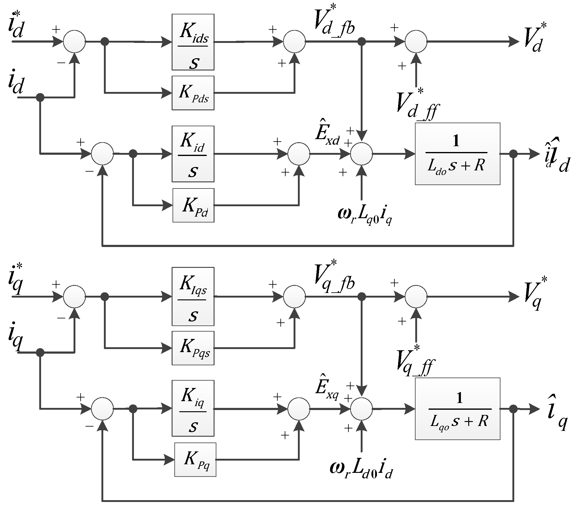
well. The estimators (21)–(23) are depicted in
Figure 2, together with a typical PI plus forward current control. By substituting Equations (8) and (9) into Equations (13) and (14), we can observe that the forward current controls
and
in
Figure 2 can be represented as
and
respectively.
and
denote the voltages commanded through feedback current controls.
In order to guarantee the convergence of , we obtain the transfer function from to .
Combining Equations (21)–(23) yields
In order to obtain a stable estimator, or to move all poles to the left half-plane, and should be met. can be chosen to be positive in order to avoid the non-minimum phase. It is noted that a unit DC gain is guaranteed in Equation (26) since the following relation holds:
In a similar way, to estimate
,
can be estimated from
and
. The bandwidth of the current controller and back EMF estimator in
Figure 3 is selected as
. By the pole–zero cancellation method of the open-loop transfer function, the gains of the
d-axis current controller are determined as
The gains of the
q-axis current controller are also determined as
. The gains of the back EMF estimators are selected as
,
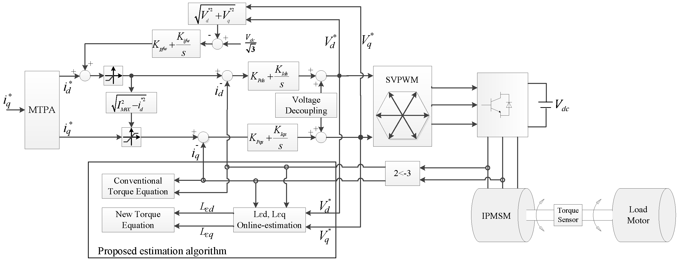
. The overall view of a control system including the estimators
and
is depicted in
Figure 4. The equivalent mutual inductances in Equations (19) and (20) are obtained from the estimated equivalent back EMFs
and
. In
Figure 4, the gains of the flux weakening controller,
and
are chosen as small as possible by the trial-and-error method because it is difficult to obtain an accurate model.
The proposed torque estimation algorithm uses the back EMF and the current value estimated using the PI state filter as shown in
Figure 3. If there are motor resistance error (
) and voltage error (
) due to dead time effects between the voltage reference and the inverter output voltage, the estimated torque error can be expressed by Equation (28):
In the high speed operation, the dead-time effect is not so serious because the relative voltage error becomes small. The estimation error of the torque due to the voltage error is insignificant. In the low speed region, the voltage error due to dead time effect is relatively large and the speed is minimal. Therefore, the torque estimation error has a larger value than its value in the high speed region. In this paper, the dead time is set to 3 μs. To reduce the voltage error, the error caused by the inverter is identified and is used in the voltage compensator, where the voltage error is cancelled [
31].
4. Simulation
In order to illustrate the performance of the proposed torque estimation algorithm, simulations are carried out by perturbing inductances and fluxes. The accuracy of the torque estimates computed from the proposed torque equation is evaluated, and is compared with that from the existing equation.
The parameter and values for the IPMSM model used in the simulations are shown in
Table 1; they are obtained from the real IPMSM employed in the experiments in this paper. The sampling frequency for control action is set at 10 kHz. A
q-axis current of 130 A is applied and the corresponding
d-axis current is determined in order to achieve maximum torque per ampere (MTPA) [
2]:
It is noted that
and
are the nominal inductances in Equations (6) and (7). For implementation, care should be taken for the zero current in the steady state. Since the mutual inductances in Equations (19) and (20) reduce to
and
in the steady state, the zero current can make the mutual inductances diverge. The proposed torque estimation scheme works well only if nonzero currents are applied.
For performance comparison, the percentage torque estimation error is computed as follows:
where
is the measured torque and
is the torque estimated using Equations (3) or (12). The percentage torque estimation error is obtained by sweeping the inductances and the fluxes from 55% to 145% of the nominal values.
A more accurate and complex IPMSM model is employed for the simulation, which takes into consideration the magnetic saturation and cross-coupling effects [
32]. Specially, the fluxes are computed from:
where
and
are the initial current and flux, respectively, and
,
,
,
,
,
,
, and
are determined to be 0.000385987, 0.0003585, 0.00208, 0.00154, 0.005, 0.001298, 40, and 0.03363, respectively. All parameter values in Equations (33) and (34) are chosen to minimize the difference between the closed-form Expressions (33) and (34) and the experimental data obtained from
Figure 1. To this end, a nonlinear least-square method is employed in this paper.
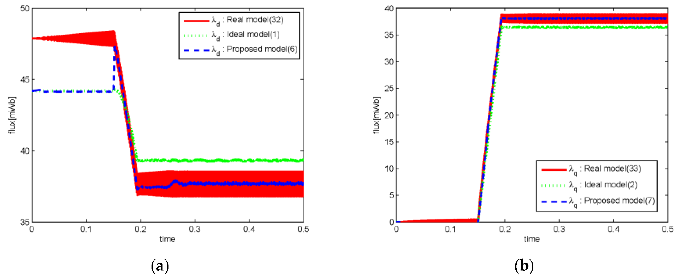
Figure 5 shows the flux computed from Equations (33) and (34), together with the one estimated from Equations (8) and (9). The current is applied from 0.15 s. As mentioned earlier, the mutual inductances are not well-defined, or diverging, for zero currents. Therefore, the
d–
q fluxes are chosen to be
and 0 at the initial time when no current is applied. These choices make sense since the
d and
q fluxes corresponding to zero current are computed to be
and 0, from an ideal flux model (1) and (2). It is observed that significant flux estimation errors are present from 0 s to 0. 15 s. After 0.15 s, the estimated flux from the proposed algorithm follows the real one from a more realistic model (33) and (34) well. It can be seen that the estimated flux from an ideal model has more biased and larger estimation errors than that from the proposed algorithm. In particular, more significant performance improvements are obtained in estimating the
d-axis flux.
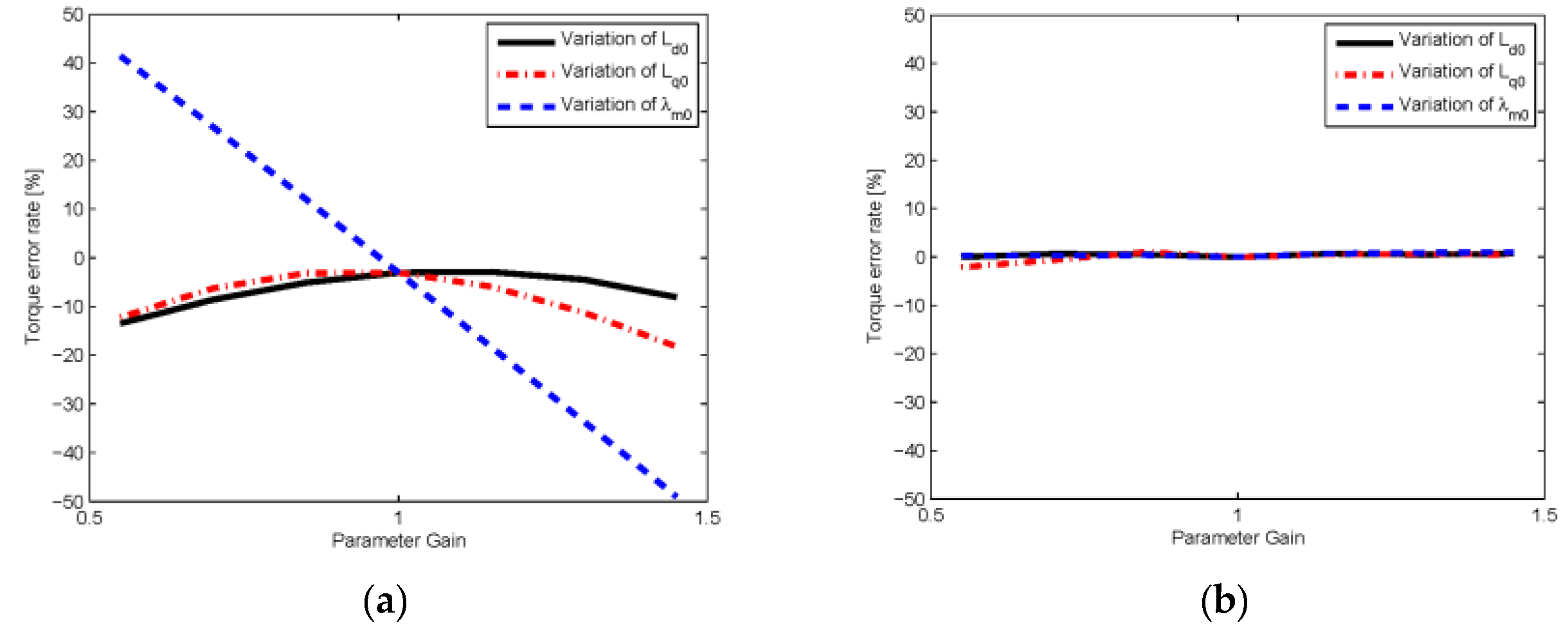
Figure 6 shows the percentage torque estimation errors due to the inductance and flux variations.
,
, and
are swept from 55% to 145% of the nominal values in steps of 15%. The conventional torque equation provides estimation errors between −18% and 3% due to
and
variations. The percentage torque estimation error due to the
variation is more significant; it varies from −49% to 40%. The proposed torque equation provides a small estimation error between −2% and 0.9% due to
,
and
variations. Even though the parameter values are quite different from the nominal ones, the estimation errors obtained from the proposed torque equation are still around 0%. The torque estimation scheme based on the proposed torque equation can be said to be adaptive and robust to various model uncertainties. Compared with the existing torque Equation (3), the proposed one (12) demonstrates superior performance while estimating the torque.
5. Experiment
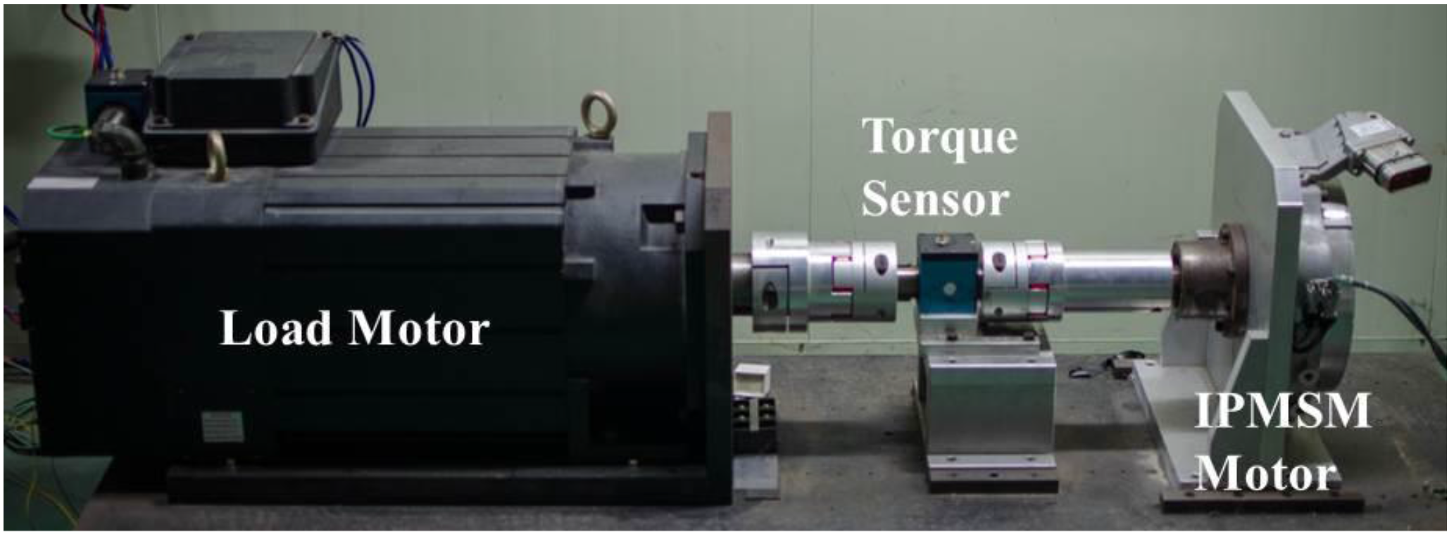
Figure 7 depicts the experimental set up. All parameters of the IPMSM used for the experiment are the same as the ones used for simulation. A torque sensor is employed to measure the real torque and compare it with the estimated one computed from the torque equation. As in the simulation, we sweep
,
and
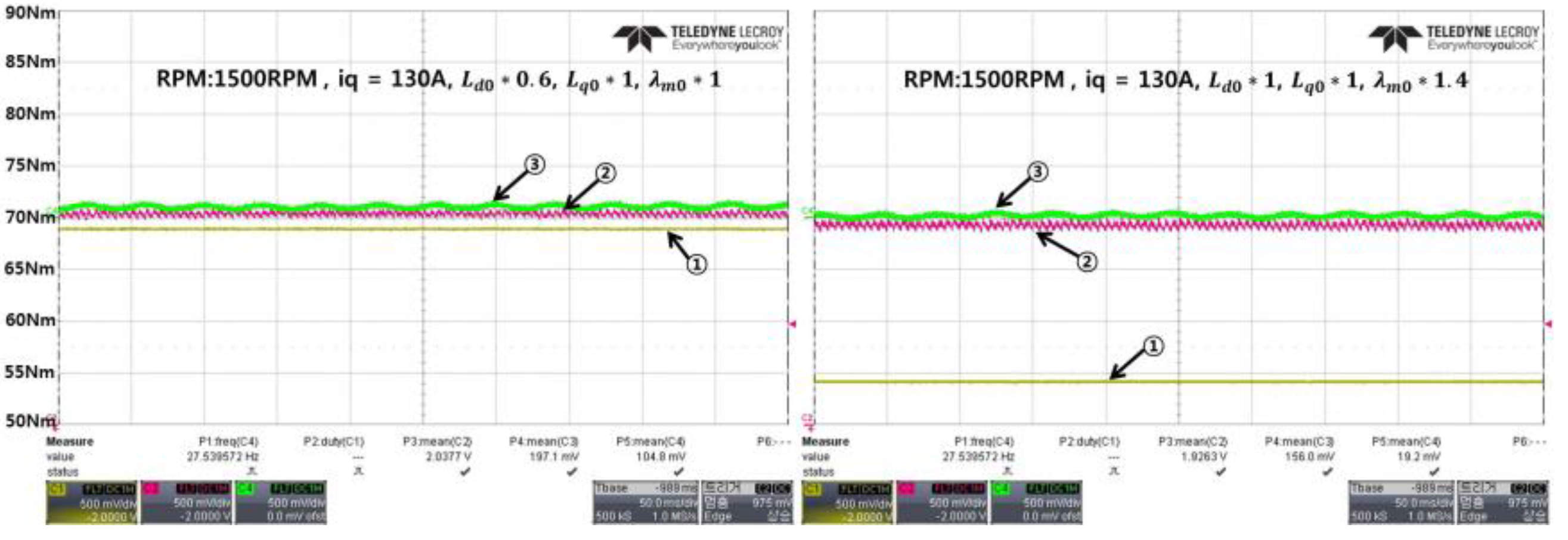
from 55% to 145% of the nominal values in steps of 15%. For each inductance and flux, the experiment is carried out as shown in
Figure 8. ①, ②, and ③ correspond to the torque values based on the conventional torque equation, the proposed one, and the torque sensor. The experiment is repeated for all parameter variations.
Figure 9 shows the percentage torque estimation errors due to the inductance and flux variations. The existing torque equation provides estimation errors ranging from −4% to 21%, −7% to 25.9%, and −28% to 46% due to the
,
, and
variations, respectively. As in the case of the simulation, the torque estimation error due to the
variation is the most sensitive. The proposed torque equation provides a small estimation error of −0.3% to 0.7% due to the
,
and
variations, which is consistent with the simulation results. Overall, the experiment illustrates the good performance of the proposed torque estimation scheme better than the simulation.
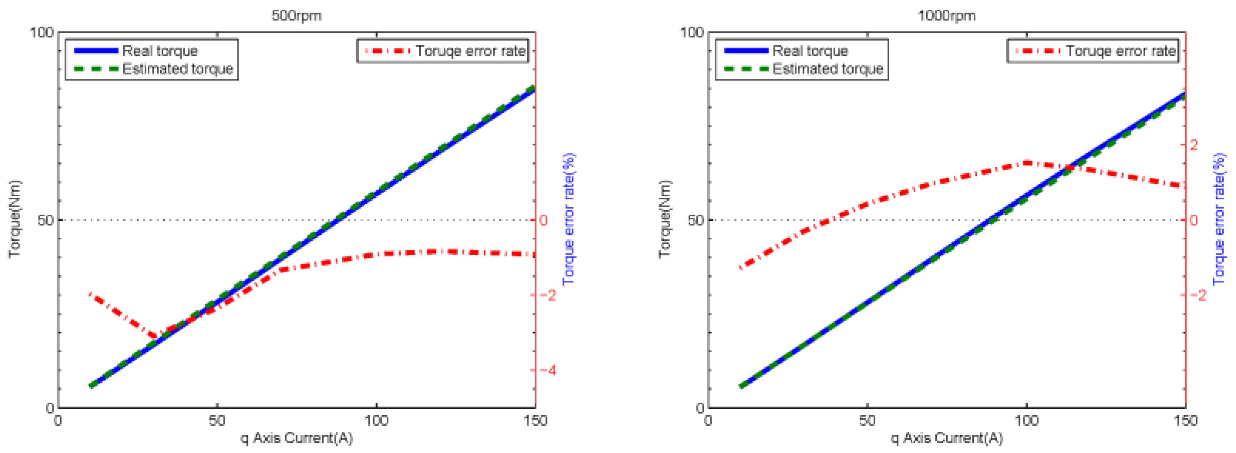
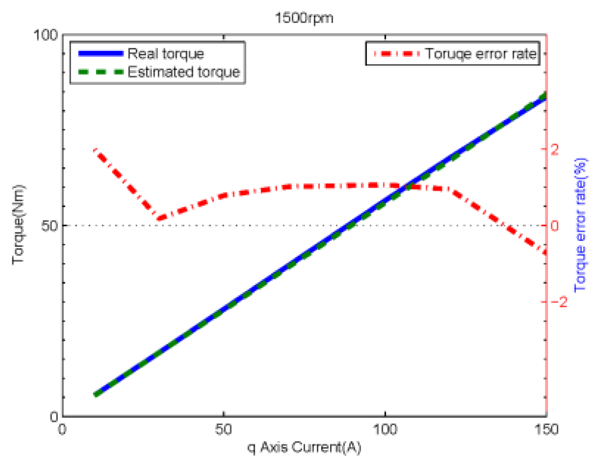
In order to verify the proposed torque equation, the experiment is carried out for various speeds and applied currents. The speed takes values of 500 rpm, 1000 rpm, and 1500 rpm. The current is chosen to be 10 A, 30 A, 50 A, 70 A, 100 A, 120 A, and 150 A.
Figure 10 shows the torques and their percentage estimation errors against the
q-axis currents for the three different speeds. The largest torque estimation error occurs for a current of 30 A at a speed of 500 rpm. As a whole, the estimation error comes within 5%.
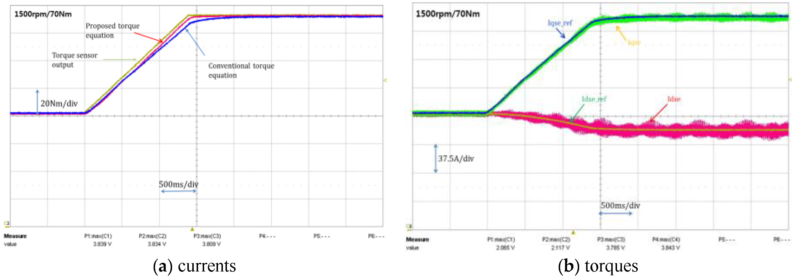
Figure 11 shows torque estimation results when MTPA operation is performed while increasing the
q-axis current from 0 A to 130 A in ramp form at a constant speed of 1500 rpm. It is possible to confirm that the proposed torque estimation method is more accurate than the conventional method in the steady state as well as in the transient state by following the actual torque better than the conventional torque calculation result.


