1. Introduction
In the power system field, there are several new paradigms of power grids which are trying to address various issues [
1]. In the past decade, the emergence of technical innovations and changes in countries’ economic and international regulations for the environment has extended interest in renewable energy generation using distributed energy resources (DERs) such as gas turbines, micro-turbines, photovoltaic cells, fuel cells and wind turbines [
2]. The increasing penetration of distributed generations (DG) has side effects on the power quality, reliability, and security of a network. The addition of advanced integration technologies (IT), control methods, and integrated communications to conventional electricity grids has resulted from the formation of smart grids. In integrated energy systems, also known as microgrids (MG), smartness refers to the ability of control and management of energy consumption and production [
3].
The microgrid basically involves DGs, renewable energy sources, clusters of controllable loads and distributed storages operating in a coordinated manner to reach distinctive objects. Microgrids are expected to improve power quality, reduce transmission losses, provide system reliability and reduce energy prices.
Microgrids are operated in two different modes. The first one is the grid-connected mode, wherein a microgrid is connected to the grid. Based on the management aims, it can inject power into the network or absorb energy from the grid [
4]. The second mode is the islanding operation. In this mode, local generation should provide enough energy for demands. Maintaining the balance of power between supply and demand is challenging in this mode. Moreover, storage participation, load shedding and demand-side management are used to increase security [
5,
6]. In such a case, even the least perturbation in loads can produce large transient deviations in voltage and frequency, since there is no inertia in the microgrid.
The microgrid control is the essential approach between other microgrid research domains. Control architecture can be categorized in two basic terms; central and decentralized control. The central controller directly provides control commands to all components of the microgrid. It collects relevant information from the component within the microgrid to issue optimal control set points to the controllable units. The centralized architecture has different objectives such as power scheduling [
7,
8], energy management [
9], operating costs and load sharing [
10,
11]. Centralized control requires a powerful communication system, and it cannot operate properly if its communications systems are interrupted.
The second approach is a decentralized control. In a decentralized control, the responsibilities and tasks are assigned to the DER controllers [
12]. Therefore, controllers do not need complex communication infrastructure.
From centralized to decentralized control, there are several levels of decentralization in decision making. One of these levels is multi-agent control. Organization of intelligent agents through several fewer intelligent agents are performed by a multi-agent system (MAS). The MAS has high intelligence to control or plan the behaviors of its own agent according to the change of environment [
13]. The multi-agent technology is the evolution of the classical decentralized technology with some specific characteristics that provide new capabilities in controlling complex systems [
14]. Nowadays, MAS is widely used in microgrid applications [
15]. Research on MAS varies, ranging from market operation to fault protection and distributed energy management systems. In addition, requirements for the use and applications of MAS in power systems are discussed in detail [
16]. Inherent benefits such as flexibility, scalability, autonomy and reduction in problem complexity among other factors promote MAS in the power system. Another issue is the architecture and topology of the multi-agent systems [
17,
18].
The prediction of the future of microgrids shows that it will move toward the hybrid AC-DC microgrids. This article tries to take advantage of a new multi-agent system (MAS) method for the hybrid AC-DC microgrids. This article has developed a hierarchical multi-agent system (HMAS). In addition, a distributed algorithm is developed for HMAS to increase the speed of decision making in multi-agent control in a hybrid microgrids. In this paper, a network is simulated with distributed generation DC and AC, load, and storage resources to investigate the designed control system on frequency and voltage stability of the microgrid with energy storage resources in the hybrid network. Furthermore, all studies will be rationally done in the islanding mode since this is common situation in microgrid operation. Article topics are organized as follows.
Section 2 explains the microgrid control and management.
Section 3 introduces the hybrid microgrid control.
Section 4 describes the Multi-Agent Controller.
Section 5 describes the new architecture for multi-agent control.
Section 6 provides a simulation of a microgrid and discusses the results. Finally, the last section provides the conclusion.
2. Microgrid Control System
A microgrid is an essential part of future distribution networks. Thus, the increased use of microgrids in distribution networks will warrant changes to the traditional controllers. The control philosophies of microgrids are categorized into three fundamental methods:
Centralized control
Decentralized control
Hierarchical control
- a.
Centralized Control
Centralized Control is a common and traditional microgrid control method. There are two ways of controlling MGs in the centralized mode. In the first method, one DG controls other DERs. In the second mode, a central decision-making unit controls the MG. Centralized control gathers all data from all instruments in the microgrid and makes decisions based on these data.
Centralized Control will be a convenience for application of accurate optimization algorithms and broader observability of the operation of the whole system. Clearly centralized control has some disadvantages such as lack of flexibility and easy extensibility (it is not a modular controller), and high costs for communication, designing and computing facilities are highlighted.
- b.
Decentralized Control
Another controlling approach is uncoordinated control. In decentralized control, each unit performs its task independent of other units. Meanwhile, reducing exchangeable information can reduce the demand for an expensive communication network. Moreover, it provides plug-and-play capability for installing additional DER units and consumers in the microgrid.
In decentralized control, the probability of instability of the network is high because each inverter makes a decision based on local measurements. Furthermore, through the time of operation demand and generation capacity, their locations may change. Because they operate in an independent manner without knowing anything in regards to the new scheme of the grid, decentralized controllers make decisions which increase the probability of grid instability. Therefore, it seems decentralized control without cooperative control is not stable.
- c.
Hierarchical Control
Through time, the objects of the control system become complicated. In the past, islanding and grid-connected microgrid applications have been considered as separate approaches. Nowadays, microgrids are required to be able to operate in both the grid-connected and islanded modes [
19,
20]. After deregulation, profit maximization is one of the important issues in microgrids. Therefore, these concerns have completely changed microgrid operations. It seems that hierarchical control is the better option in this situation since its controlling objects are organized into three levels:
- 1-
Primary control: Primary control is a low level control. It is in contact with the DG inverters because most DGs are connected to the grid through the inverters. Also, this control level adjusts the frequency and amplitude of the voltage reference provided to the inner current and voltage control loops as in the prime mover. It is a virtual prime mover. This principle can be integrated in VSIs by using the well-known P/Q droop method.
- 2-
Secondary control: Power management was performed by primary control. It regulates active and reactive power by changing the frequency and the voltage, respectively. The frequency and voltage amplitude deviations are compensated by secondary control. The secondary control ensures that the frequency and voltage deviations are regulated toward zero after every change of load or generation in the microgrid [
21]. Therefore, the microgrid will work in the nominal condition.
- 3-
Tertiary control: Different techniques can be used to generate profit from a microgrid. One of them is participating in the energy and ancillary services’ markets. In this case, power flows between the grid and the microgrid should be regulated by tertiary control at the point of common coupling (PCC). This control is used in the grid-connected mode to adjust the power flow of a microgrid [
22].
3. Hybrid Microgrid Controllers
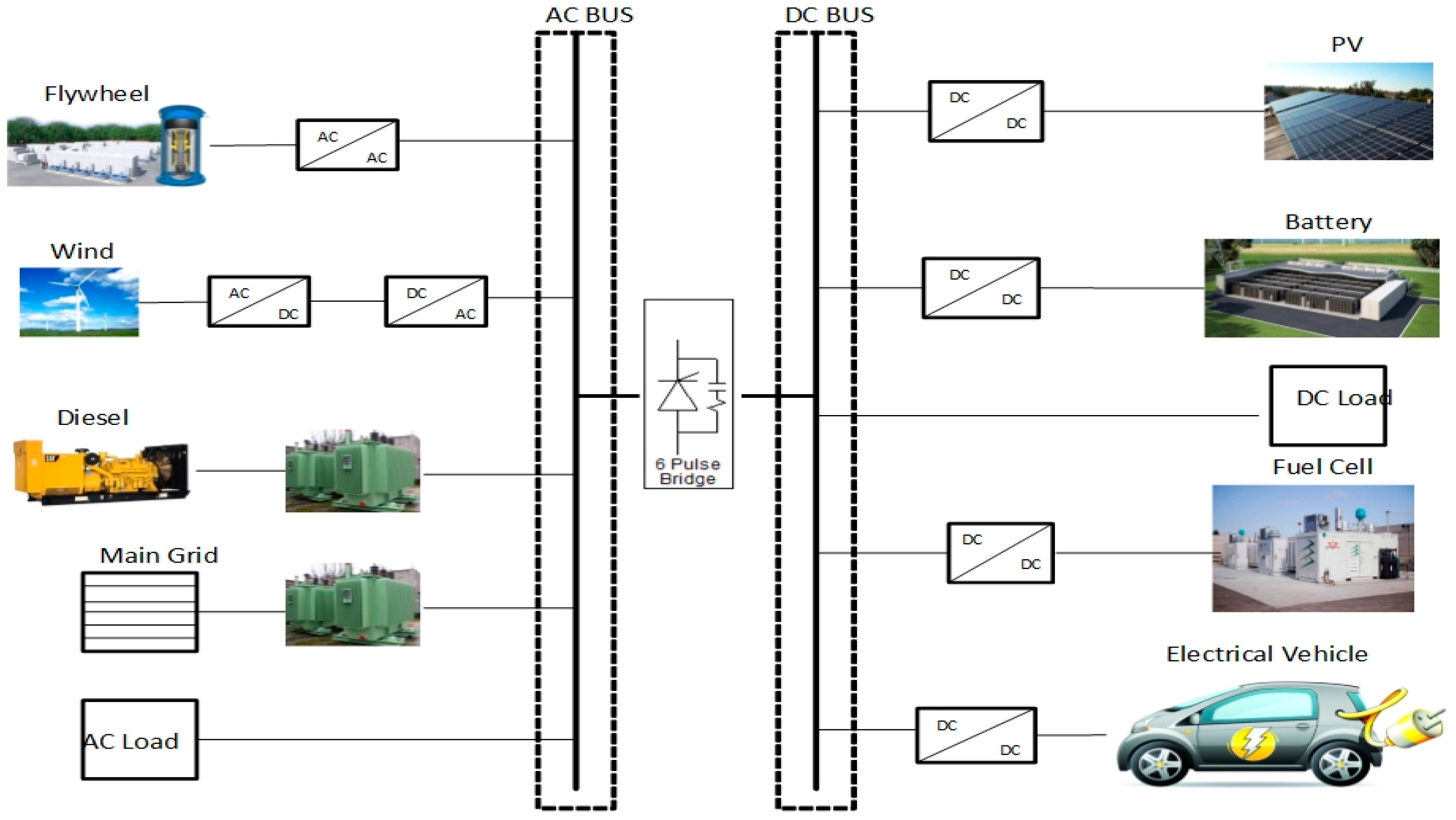
In a DC microgrid, energy storage devices and many sources and loads are interconnected through one or more DC buses. However, there will still be a need for AC microgrids because some sources and loads cannot be connected directly to a DC bus. Another prominent recent development in AC power systems is the addition of DGs and microgrids for integrating renewable power sources such as wind turbine generators, photovoltaic (PV) panels, fuel cell generators, energy storage systems (ESS), and electric vehicles (EV) into local distribution systems. Therefore, future grids will facilitate the connection of various AC and DC generation systems, energy storage options, and various AC and DC loads with optimal asset utilization and operation efficiency. In this way, a hybrid AC/DC microgrid reduces the multiple reverse conversions required in individual AC or DC grids (
Figure 1).
Moreover, centralized or decentralized control can be implemented. The main objectives of system control, consisting of individual controls of inverters, converters, and charging/discharging controllers, are to maximize the energy harvested from renewable sources and minimize power transfer between AC and DC sides under different system loads and resource conditions [
23].
Liu et al. [
24] proposed coordination control algorithms for smooth power transfer between AC and DC links and for stable system operation under various generation and load conditions. Moreover, some uncertainties of DER and loads are considered in system control and operation. When a hybrid grid operates in the connected mode, the control objective of the boost converter is to extract the maximum amount of power from renewable resources. The battery’s role becomes less important because the power is balanced by the utility grid. Moreover, to smoothly exchange power between DC and AC grids and supply a given amount of reactive power to the AC link, the PQ control is implemented using a current controlled voltage source for the main converter.
Distributed storage (DS) is one of the important parts of a hybrid microgrid. Power flows of DSs are bidirectional and are not decided solely by the total load demand. Most DSs have some form of a localized energy management system (EMS). This system investigates the active power sharing of an islanded hybrid microgrid. Sharing of power across both AC and DC grids, however, cannot be enforced by relying only on the droop control of each grid. Droop control of the interfacing converter is executed first by measuring its immediate DC-link voltage and AC frequency, decided by the micro-sources found in the AC and DC sub-grids, respectively, before determining a single active power quantity for tracking [
25,
26].
4. Multi-Agent
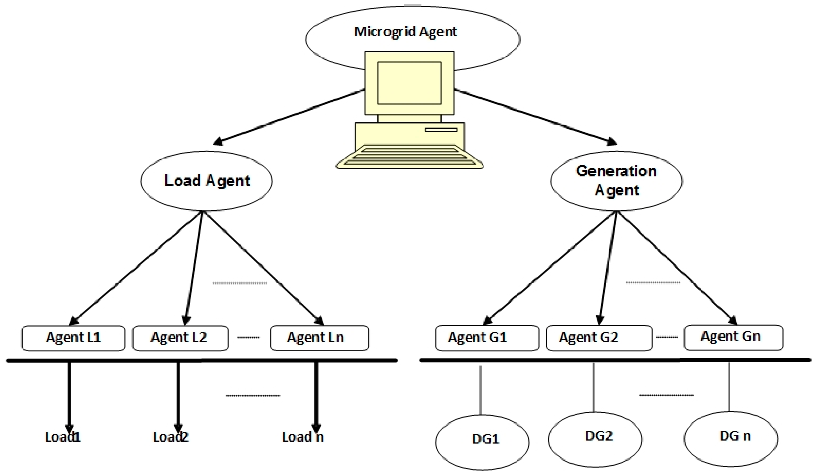
A multi-agent system is a combination of several agents working in collaboration with one another, pursuing assigned tasks to achieve the overall system goal [
27]. Some basic characteristics of agents have been provided through the literature [
28,
29]. The first characteristic is that an agent can be a physical entity. Moreover, agents can act in the environment and communicate among each other. Agents can make decisions without a central controller or commander. Finally, another significant characteristic is that an agent has a certain behavior and tends to satisfy certain objectives using its resources, skills, and services (
Figure 2).
In the context of power systems, multi-agent technologies can be used in a variety of applications, such as power system disturbance diagnosis [
30], power system restoration [
31] and power system secondary voltage control [
32]. Agents in the multi-agent system interact cooperatively [
33] to optimize the operation of the microgrid. Moreover, some of the most recent works [
34] have implemented MAS to control microgrid operations. Power system modeling based on a multi-agent is a promising approach to provide a common communication interface for all equipment. Moreover, the nature of distribution and potential for modeling autonomous decision-making entities in solving complex problems motivates the use of MAS [
35]. The presented paper uses MAS for secondary microgrid control. Each agent can perform its tasks independently. Furthermore, agents can have some data exchanged concurrently to improve their operations. Thus, this scheme reduces communication requirements. Moreover, the control logic can be changed based on different societies’ agents defined for MAS levels.
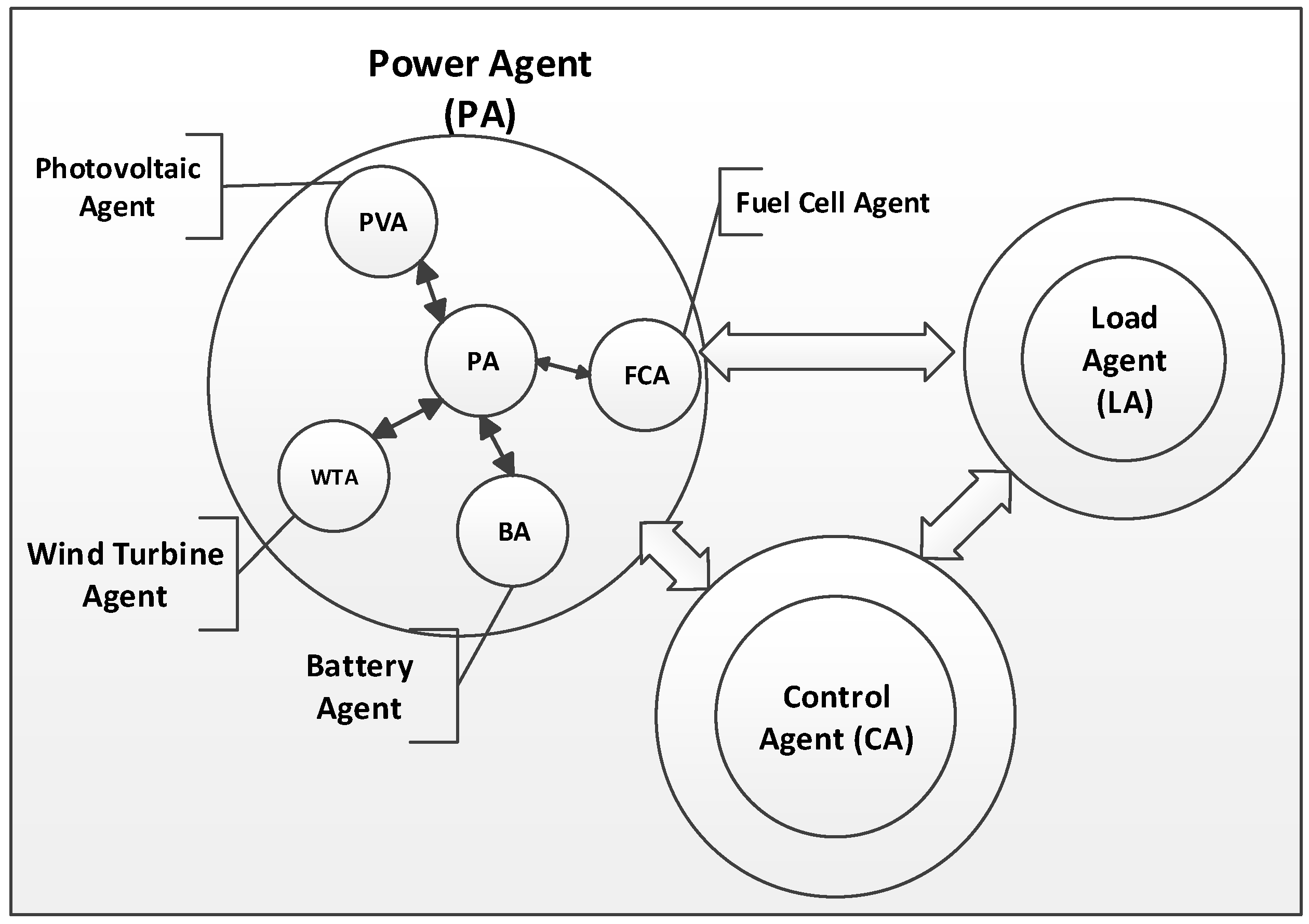
Agent structures: Each agent performs its own function autonomously. The function is constructed by a set of behaviors. They are divided into three groups corresponding to their different functions and goals (
Figure 3).
Power agent: For DGs, local control is used to regulate their output power dynamically in response to frequency and voltage changes. This agent is used to analyze data, control the specific DG, and negotiate with other agents to decide the output power for a certain control objective. This agent encompasses for other agents that are defined as below. This agent has fixed data such as unit name, minimum and maximum power limit, slopes of droop control, and variable data such as power setting and status.
Photovoltaic agent (PVA): a photovoltaic agent corresponds to a photovoltaic generator. The PVA replies to the amount of electric power, according to the request from microgrid controller.
Wind-power-generation agent (WPGA): It is corresponding to the wind power generator. The WPGA replies to the amount of electric power, according to the request from microgrid controller.
Battery agent (BA): Battery agent corresponds to the DC bus. The BA replies to the amount of electric power according to the request from microgrid controller.
Fuel cell agent (FCA): Fuel cell agent corresponds to the wind power generator. The FCA replies to the amount of electric power, according to the request from microgrid controller.
Load agent: Load agent is used to analyze data, control the specific load, and negotiate with other agents the desired power.
5. Event-Driven Microgrid Control Management (EDMCM)
Producer-consumer organization, agent communication and event-driven functionality will be defined in proceeding sections. They are used firmly in microgrid management.
5.1. Producer-Consumer Organization
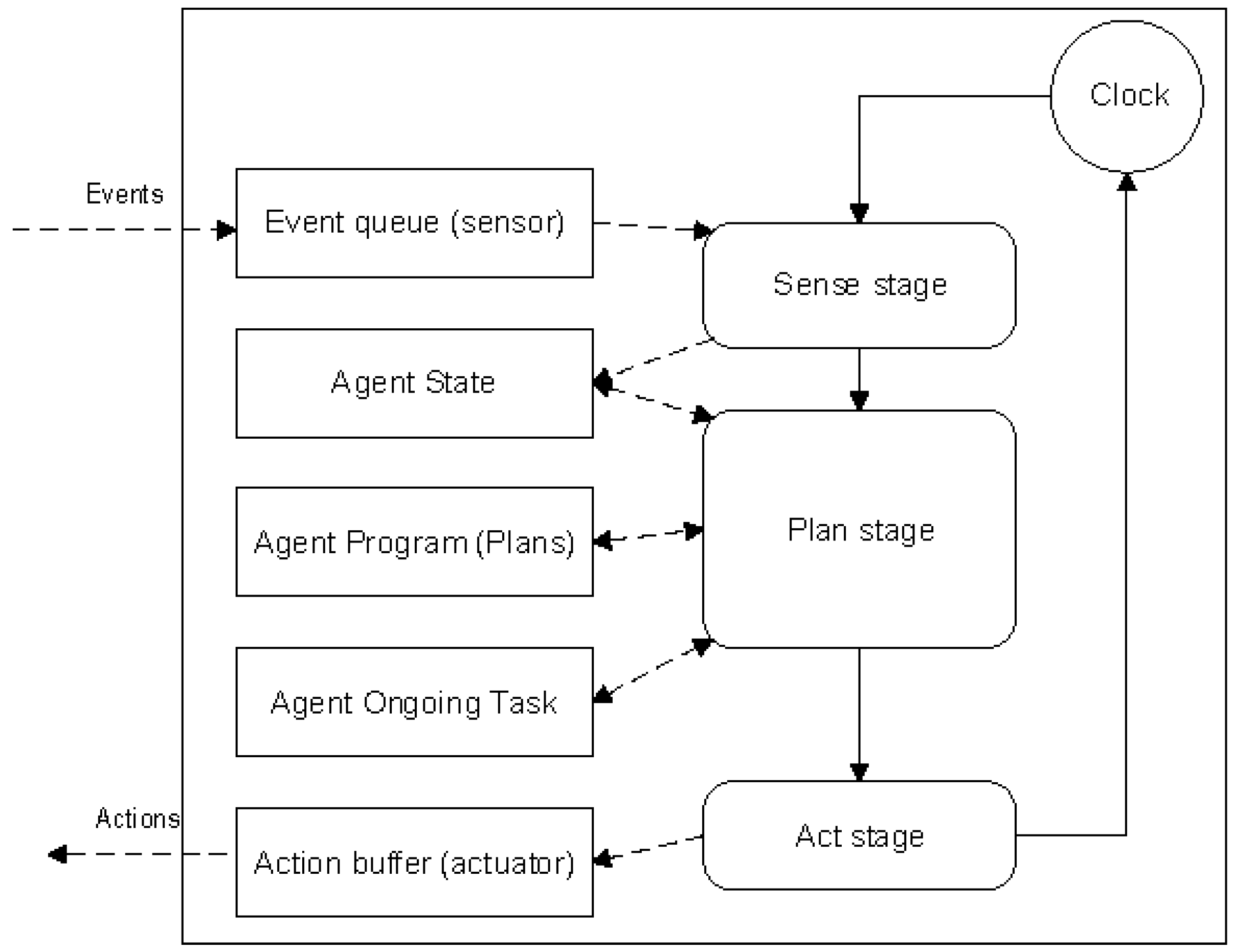
Producer and consumer agents have a different structure. Consumer structures are shown in
Figure 4. First, the agent sensors sense the events in the real grid and send data to the sense stage. In this stage, the state of the agent will be changed by sensing an event. At this time, the agent state, the agent program and agent ongoing have communication with each other in the planning stage. Finally, the planning stage makes a decision and sends it to the action stage.
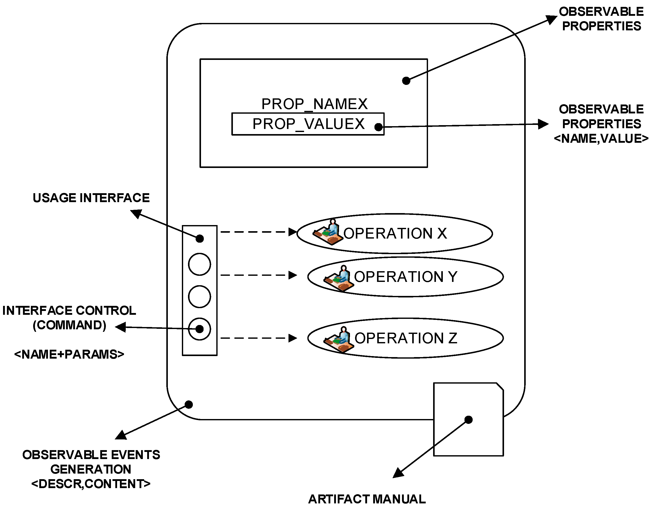
Figure 5 shows the producer model in multi-agent system. Unlike the consumer agent, which only senses the situation and will follow a set of instructions, it checks the local conditions of production and makes a decision to improve the microgrid situations. In addition, there is an artifact manual for each producer agent.
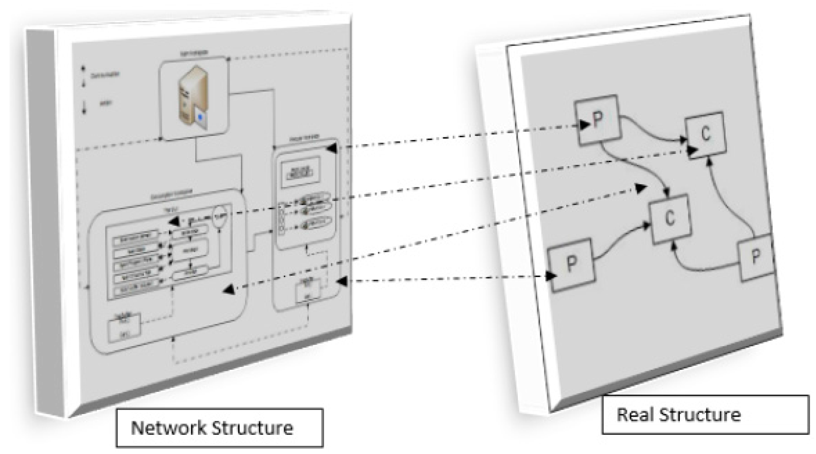
A composed physical and computer layer microgrid is depicted in
Figure 6. Both layers are connected through the communication lines. Physical layers are composed of producer, consumer and distribution lines. On the other hand, computer layers consist solely of agents connecting through telecommunication systems.
5.2. Communication
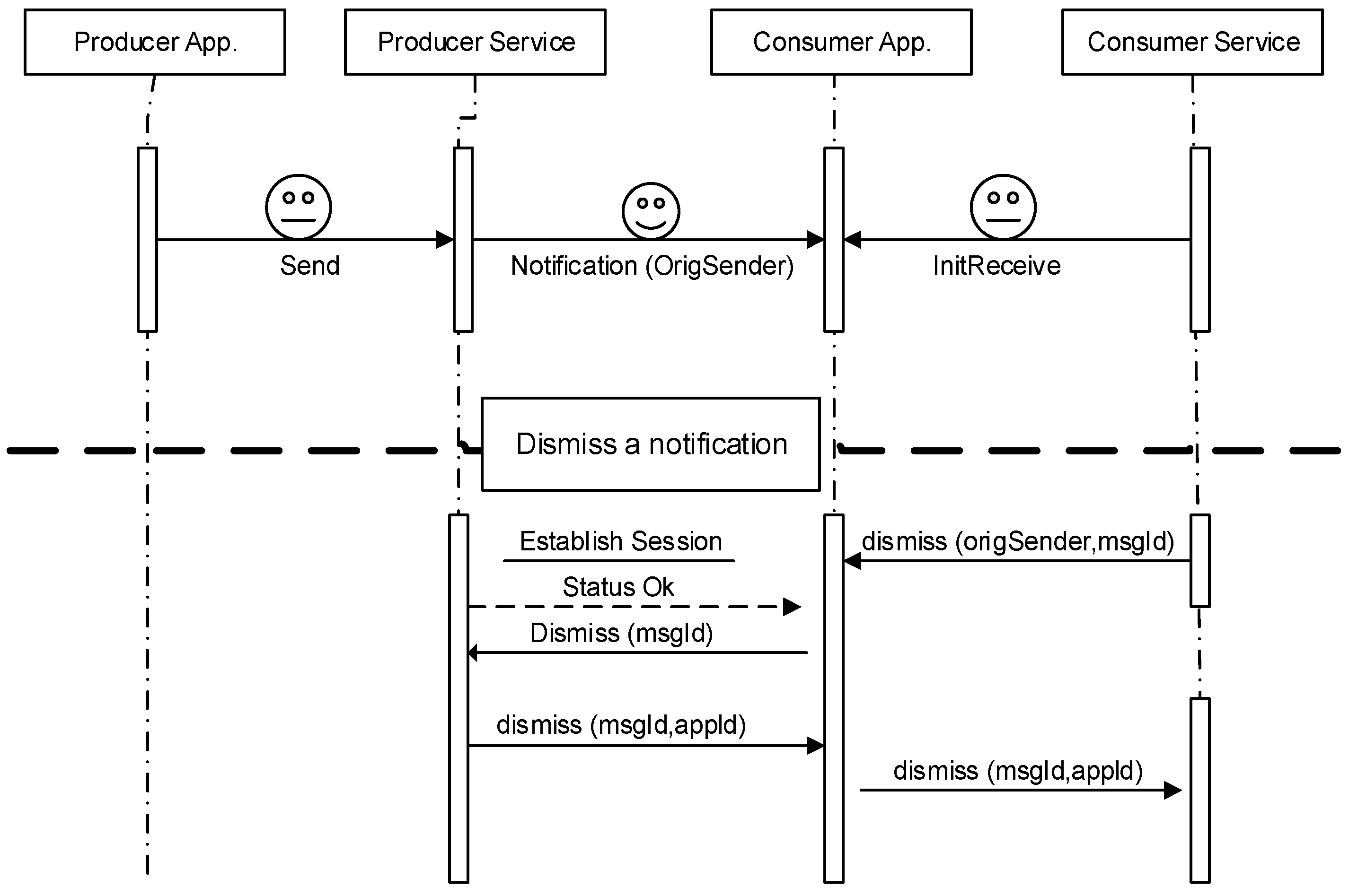
On a communications level, intelligent agents actively communicate with each other. In fact, the agents themselves are a reason to change for the better and not stay waiting for an event to improve the network. The agent interactions and exchange of information for load shedding, and their increase of production, are shown in
Figure 7.
Producers and consumers communicate and interact through various protocols, namely the hello-walker, recommendation protocol, power service, and load service. The hello-walker is only used for bootstrapping new agents in the network. The recommendation protocol is used by the loads app to exchange opinions of the services provided by the producers’ app. The power service is simply a message freebie from the power app to the consumer that they can try a service for free. The load service is similar to the power service, except that the consumer agent selects the service based on the opinions received from its peers, instead of as a result of the power’s service message.
A session will be established after receiving the dismiss message. Thus, the power agent and load agent start the diagnosis, checking the status of the session. Finally, agents will negotiate to reach a solution for the event.
5.3. Agent Functionality (Producer Agent Model-Consumer Agent Model)
In this paper, an Event-Driven Microgrid Control Management (EDMCM) is proposed. The EDMCM regulates the power for each DER unit by the lower level unit agent, and the regulating AC voltage, DC voltage and frequency are implemented through the upper level coordinated control agent.
The lower level unit agent is designed as a reaction layer. The reaction layer is defined as “recognition, conception and action.” By default, this layer which is set to be performed has priority to quickly respond to power changes in microgrid. For instance, the reaction layer of the unit agent can figure out a sudden change of power, to determine whether to switch its operating mode.
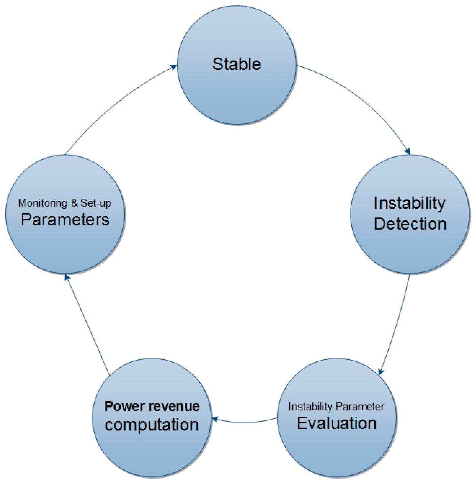
The upper level coordinated control agent is designed as an advisory agent. Its purpose is to coordinately control the operating modes, to ensure the regulating frequency and voltage in DC and AC buses. The advisory layer that is defined as “belief, desire and intention” has higher intelligence to control via the local control strategies, to achieve its intention. The local control strategies are constituted based on knowledge data and state evaluation and are implemented through the action module. Its management stages can be defined as follows:
- 1-
Stability
- 2-
Instability Detection
- 3-
Instability Parameter Evaluation
- 4-
Power Revenue Computation
- 5-
Monitoring and Set-Up Parameters
As mentioned before, this paper uses five stages for solving the problem in the microgrid. When instability has occurred, it is important to recognize its causes. For this stage, data collection is very important. Agents in a control system should have more information about their region. Evaluation is critical after this stage to make a good decision. Data evaluating can help the agent to conduct in the best way for decision making. After all of these stages, the agent should decide to retrieve grid from instability. This is the instability life cycle in our multi-agent system (
Figure 8). It is obvious that all stages communicate with the management system to reach the best solution.
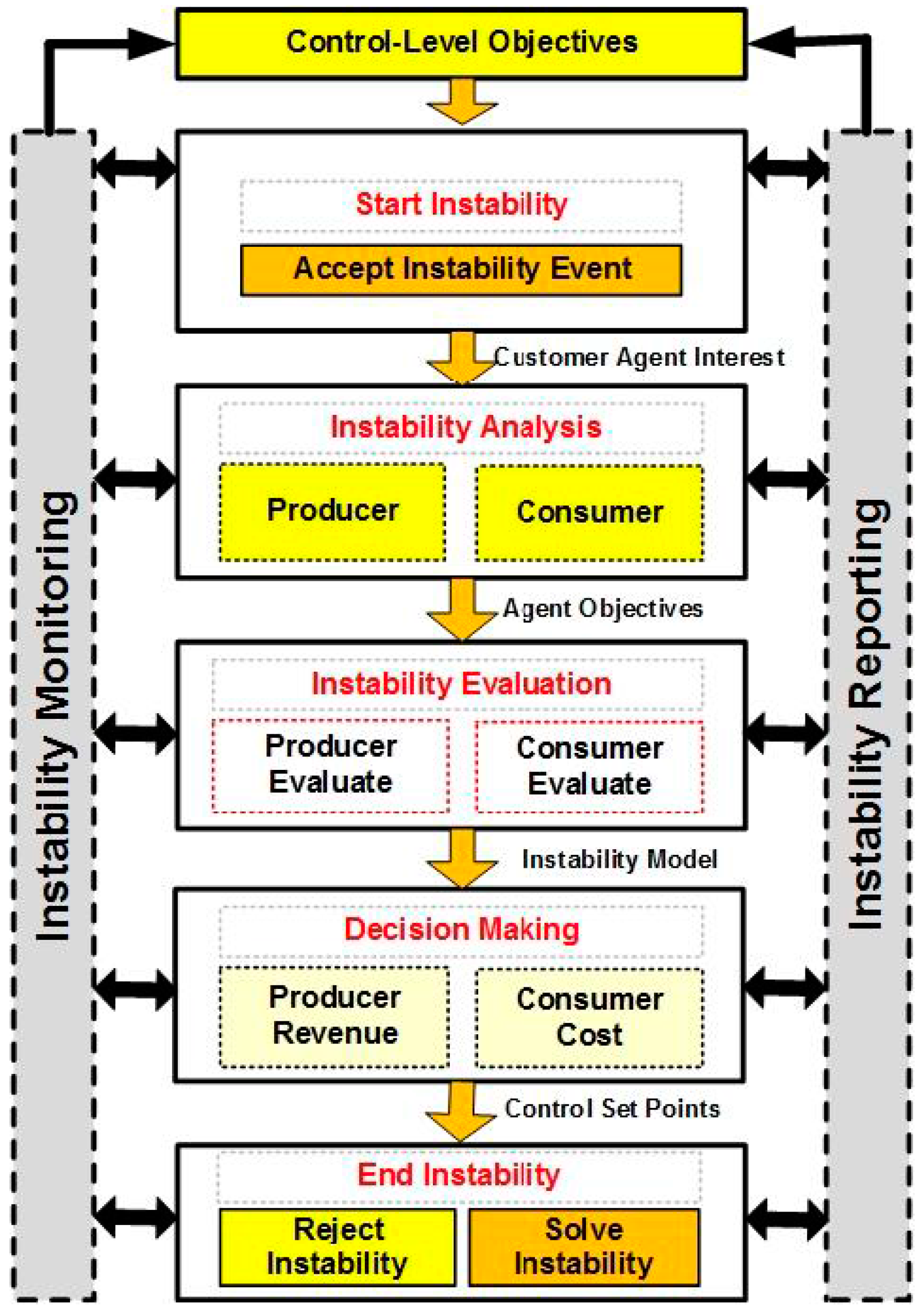
5.4. Event-Driven Microgrid Control Management States
Event-driven microgrid control management states are shown in
Figure 9. Insatiability reporting and instability monitoring is not in the scope of this paper. This paper has concentrated on the event life cycle stages. These states are defined as below.
5.4.1. Start Instability
Instability reporting and monitoring have an important role in the indications of events in a microgrid. In this stage, multi-agent controllers recognize changes in the microgrid. For instance, voltage and frequency deviation are important indexes for instability. This basic diagnosis will be the beginning of this study.
5.4.2. Instability Analysis
After accepting the instability events, the management system should analyze the event. Sometimes events change DC voltage, AC voltage or both. Each of them has its cause. For instance, when voltage is distorted, it means that the reactive power to the network has changed. In this stage, we try to specify type of events. It will be useful for evaluating the event.
5.4.3. Instability Evaluation
In this section, there are two important players. One of them is the producer that it is composed of a power agent. This player consists of all generation agents. Another player is the consumer who has one agent.
In this stage, players evaluate their subsets. Players try to figure out reasons behind an event in the grid. They will check their agent to determine if they are involved in this event or not. For example, the power agent (PA) will check whether DGs change their production or not. This state will be useful for making decisions in a correct manner in the next stage.
5.4.4. Decision Making
Producer and consumer agents will make a decision at this stage. Producer agents can change their generation to recover a microgrid after an event. Active and reactive power changing or the use of a battery in a short period can help the multi-agent controller to improve voltage deviation after events. For instance, voltage increasing at one bus can be caused by further generation in the reactive power. In this state, the controller will face a different way to solve the problem. For instance, the controller can decrease production of reactive power in DGs or use a shunt reactor as consumers based on the multi-agent controller decision.
5.4.5. End Instability
After decision making, the existing hardware in the microgrid will implement the multi-agent system decision. At this stage, the system’s task is reporting on and monitoring of the microgrid. Finally, effectiveness or the lack thereof not will be decided by them.
6. Simulation
6.1. Simulation Setup
The used machine is a Core i7-2620M 2.7 GHZ INTEL system with 4 M RAM. The PSCAD version 4.5 is used. All agents and their communication platform are developed in PSCAD by FORTRAN language.
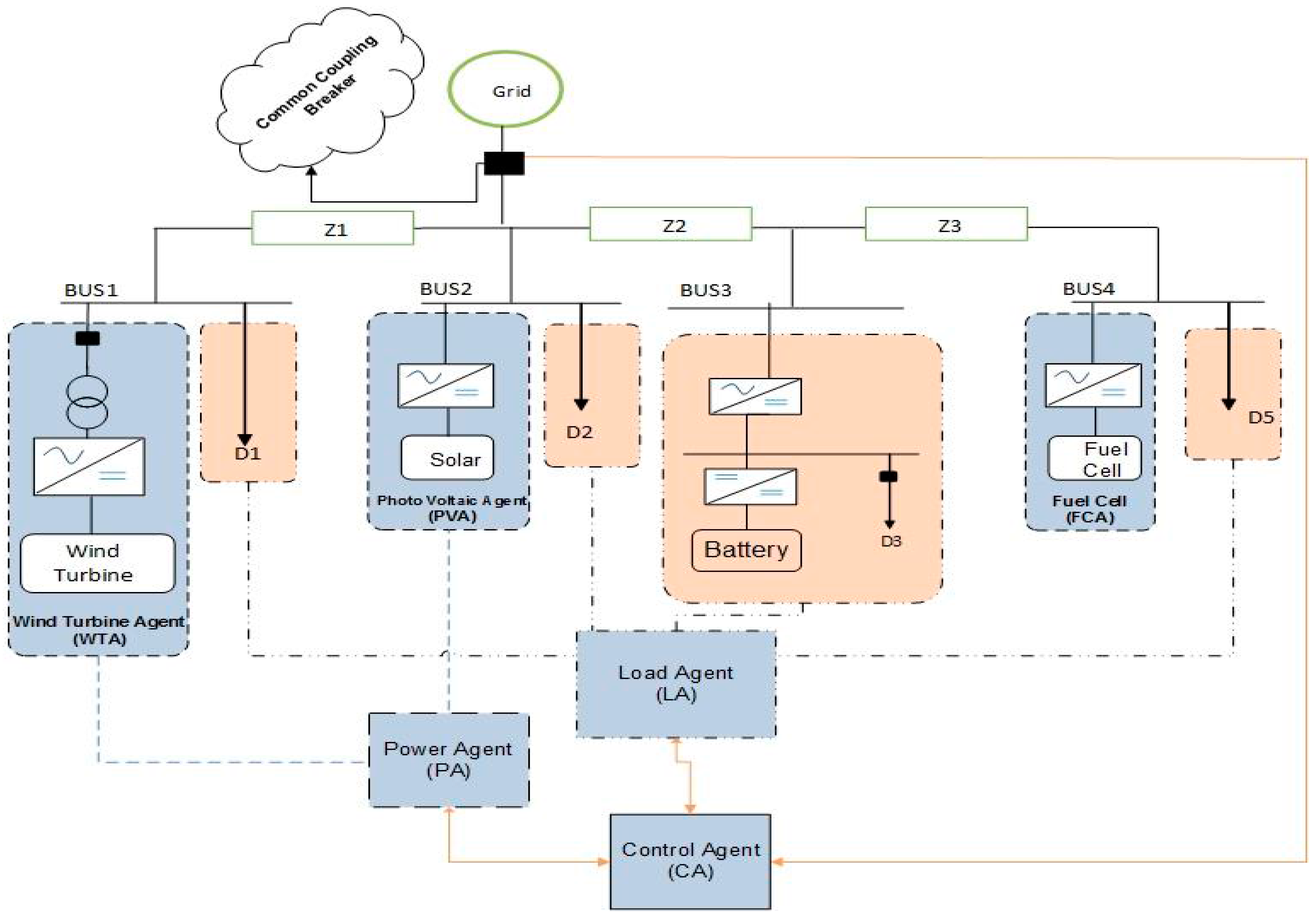
6.1.1. Proposed Network Structure
The proposed hybrid network is composed of three different DGs, four distribution lines and one DC bus providing DC voltage for DC loads and battery with a back-to-back convertor as shown in
Figure 10. Moreover, the wind generator has a VSI inverter and other generators; the PV and fuel cell have a CSI inverter. Meanwhile, dynamic (Bus1) and static (Bus2–4) loads are used in the network. Details of VSI and CSI inverters are depicted in
Table 1 as set-points and factors. Furthermore,
Table 1 shows the characteristics of lines and loads.
6.1.2. Multi-Agent Structure
Producer-consumer models are used in the proposed controller. In EDMCM, five agents are used (see
Figure 3) as below:
This model was implemented and validated with PSCAD tool by FORTRAN languages for integration and increases the accuracy of simulation results. Communications between agents are implemented based on FIPA (Foundation for Intelligent Physical Agents) protocol.
6.1.3. Design Scenarios
The proposed models are simulated under two different scenarios based on load (Scenario 1) and generation changes (Scenario 2). These scenarios are started at the third second of simulation and the result shown is for 1 second. Moreover, AC and DC voltages will be compared.
In the first scenario, a static load in bus3 with a DC voltage is connected to the microgrid. Accordingly, voltage decreasing in that bus is considerably more than other buses. Generation change is another conventional phenomenon coming up. The best point for changing power is bus4 due to its distance with VSI in bus1. Thus, generation in bus4 will be decreased in the second scenario. It is deteriorating into a deadlock in the microgrid. More details can be derived in
Table 2.
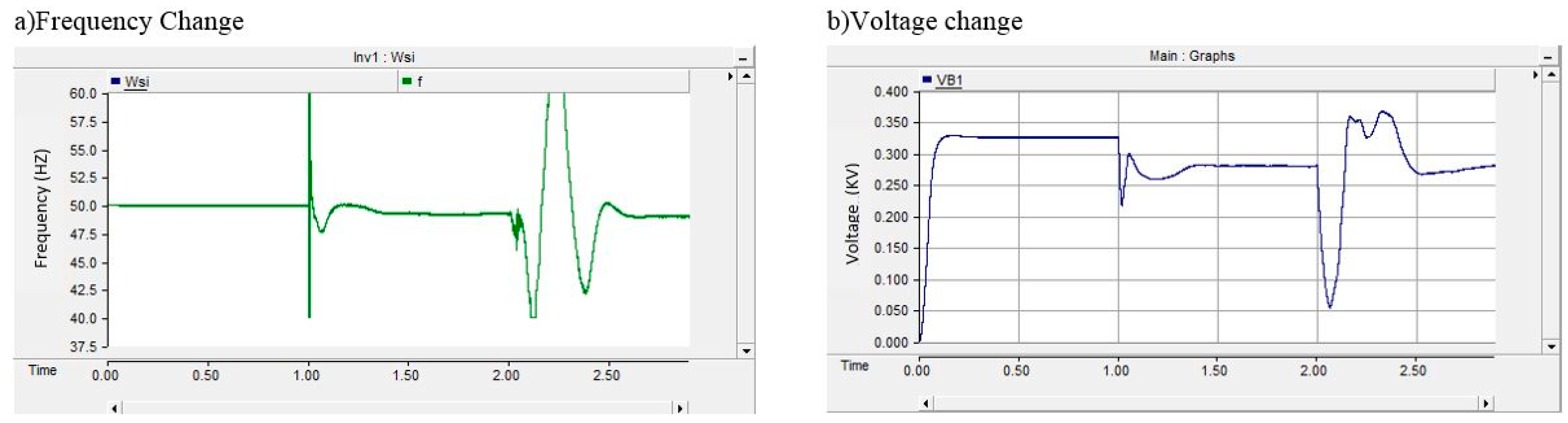
6.1.4. EDMCM Model Validation
Droop control setting validation is checked by two serious events. The first one is isolated from the grid in the first second and in the second one, the microgrid is encountered with a 3ph short circuit in bus4 in the 2nd second and takes 100 ms.
Figure 11 illustrates the obvious stability of the microgrid in these events.
Frequency after both phenomena is retained with a minimum deviation.
Figure 11a shows the control system after the removal of short circuit stabilized frequency with a minimum overshot. On the other hand,
Figure 11b depicts the control system’s preserved voltage as before occurrence of islanding and short circuit. The results therefore indicate that EDMCM control works properly and the effect of energy storage to enhance voltage in the AC-DC hybrid network can be investigated.
6.2. Empirical Simulation Results
The proposed model responses are studied in two different scenarios. Voltages of AC and DC buses are used for validating stability of the microgrid. Empirical results of two scenarios are clarified in different sections. The voltages achieved in both scenarios have indicated EDMCM had the best result. However, details of these scenarios are discussed in the next section.
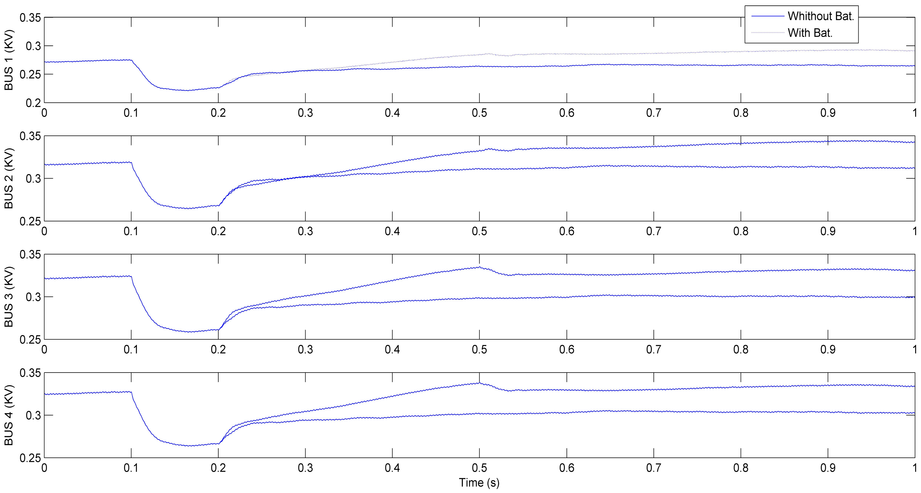
Scenario 1: Changing load is one of the conventional events in microgrids. Load profile drastically changes over the period of a day. This scenario simulates the situation of increasing load in microgrid. AC and DC voltages decrease and power loss increases due to increasing demand in the network. Thus, the amount of power generation in the network should be increased based on the changes.
In this simulation, 8 MW three-phase loads are connected in bus3. The network responses with and without presence of battery are shown in
Figure 14. EDMCM control without battery decides to increase generation as 10 MW in bus2 to return voltage to its nominal value. Using the battery in the network changed the logic of EDMCM. It uses the battery at first to overcome rapid changes in the network.
The first analysis examined is the AC voltage buses. AC voltage in both conditions with and without the presence of storage resources is shown in
Figure 12. It is clearly seen that the control system detects the load increasing during 0.1 s and has adopted the desired decisions. Also, the battery will be fully discharged within 0.3 s in the network. By injecting power in the network by way of batteries, the network’s voltage is increased and gives this opportunity to the multi-agent control system to use other resources’ power to compensate for the power drop. Voltage in different buses had improved on an average around 16%. This increase in voltage will decrease reactive power in transmission lines. As a result, network lines’ losses and congestion will be significantly reduced.
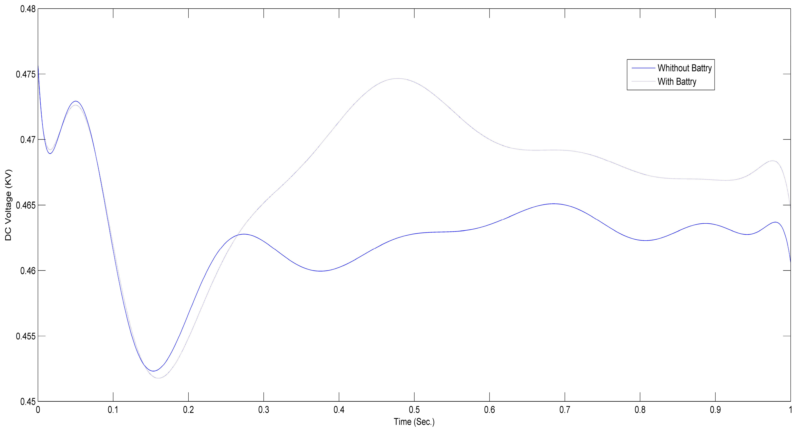
Load changes in the network are also effective on frequency. Normally, load changes will reduce the frequency and will cause instability in the network. In
Figure 13, based on the designed scenario, the load is added to the network. The results with the presence of battery and without it with the multi-agent control system are shown in
Figure 13. It is seen that if the battery is not available in the network, the voltage of DC bus will slowly increase because the response of the control resources with PQ control is slow. In the second curve, however, the multi-agent control system will simultaneously add battery into the circuit after load increase in the network. This battery significantly increases DC voltage in bus3 within 0.3 s. This procedure gives enough time to the renewable resources to increase their power to prevent DC voltage drop. In fact, as in the previous analysis, the storage resource gives the control system the opportunity to easily compensate for the delay response of other renewable and distributed generations (DG) thus increasing their production.
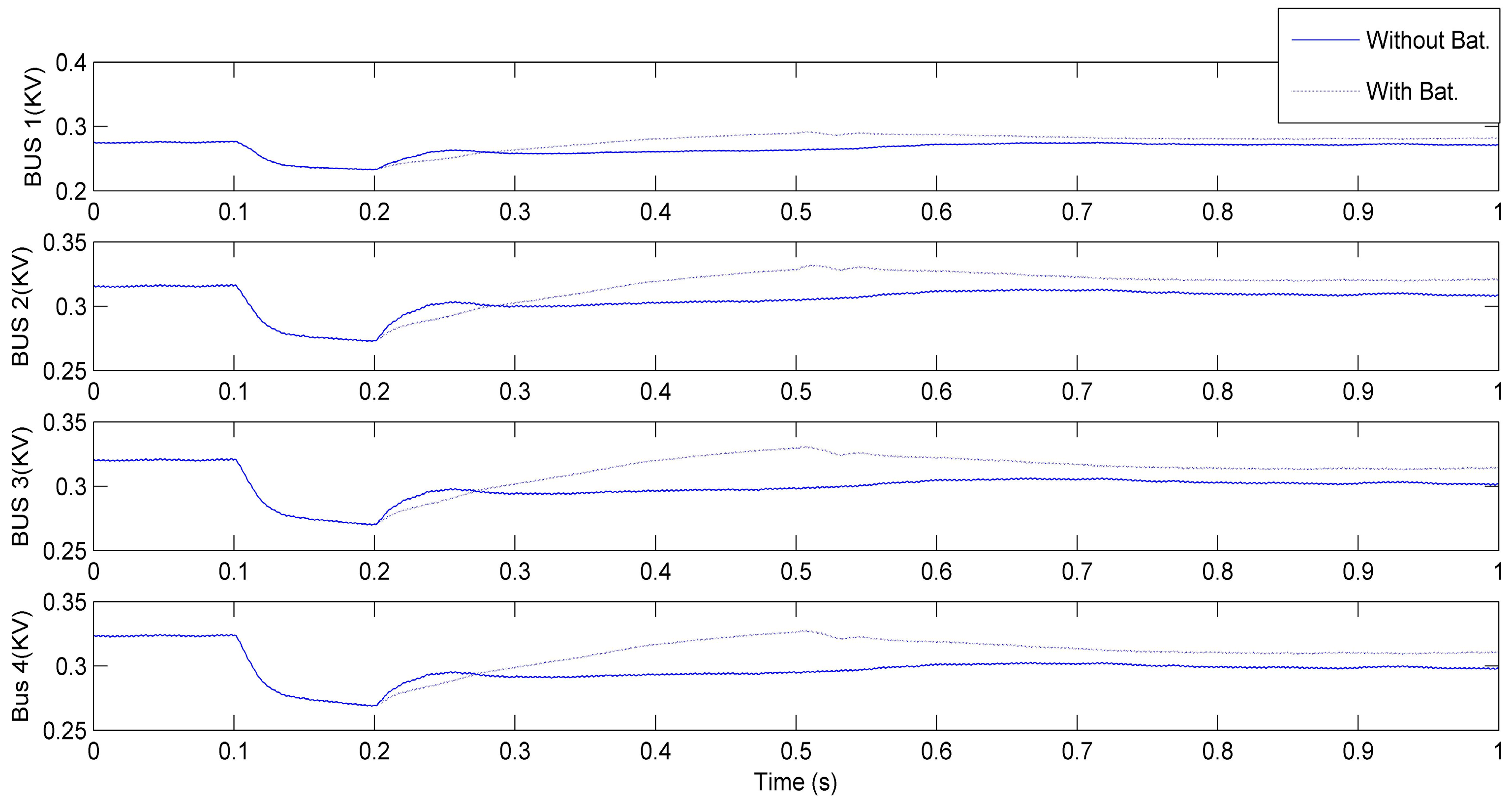
Scenario 2: Changing generation is another event in microgrids. Generators may be decreased or removed from a grid due to an unplanned program. This scenario simulates the situation of decreasing generation in the microgrid. Voltages in AC and DC buses decrease and power loss increases, resulting in decreasing generation in the network. The amount of power generations in the network should thus be increased based on the changes.
In the simulation, the active power of the PV generator in bus4 was decreased to nearly 20 MW. The network responses with and without the presence of a battery are shown in
Figure 14. EDMCM control without battery decides to increase generation as 19 MW in bus2 to return voltage to its nominal value. In the presence of battery, EDMCM has used battery to overcome instability in a short time.
Figure 14 shows voltage in buses with and without battery. The result is the same as in the previous scenario. EDMCM control with use of battery has considerably improved voltage by 10%. As a result, power losses in the network decrease drastically.
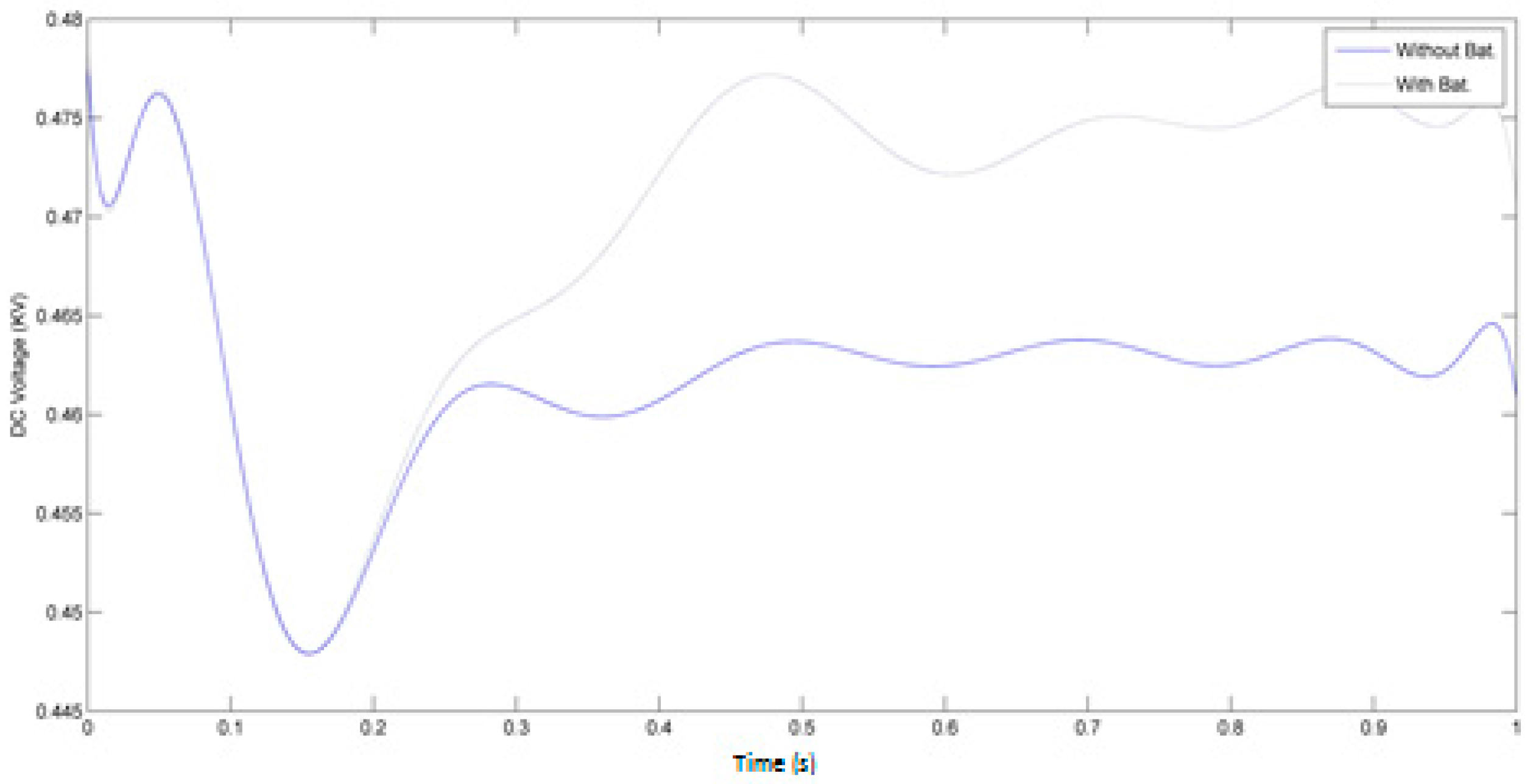
Decreasing network active power leads to DC voltage deviation. The DC voltage changes in presence of battery and without it in bus3 are shown in the
Figure 15. The results show that the energy storage agent made a correct decision to connect the battery to the grid. Battery during discharging time could increase DC voltage very rapidly. EMDCM control therefore has more time to communicate with other agents and increase power production of other renewable energy resources to compensate for losing production in bus4 by using the battery.
To summarize, a battery would help the EMDCM control in voltage improvement. Moreover, this control decreases losses in microgrid and improves power quality.
7. Conclusions
Microgrid control is one of the most important challenges in hybrid networks. The dynamics of DC buses is different from an AC network. Therefore, combining these networks resulted in a complex microgrid. Because previous control systems do not have a proper solution for a hybrid network, hierarchical central control is the conventional method in hybrid systems. A big problem is the communication infrastructure, which connects all loads and generation controllers to the main management system. If one of the connections disconnects, the control systems will encounter difficulties. Therefore, the secondary voltage and frequency control of microgrids are designed based on the event-driven microgrid control management (EDMCM) of the multi-agent system.
The second problem is that the system responses to the sudden load and production changes are quick since microgrids have very little inertia. The use of storage resources is considered the solution. These resources are located in the DC bus to reduce the numbers of converters.
The microgrid is considered as a multi-agent system with DGs, loads and main control as its agents.
Multi-agent systems need fewer communication links, and the results show that they can sustain voltage and frequency quickly. Moreover, the results show that the presence of storage resources is very effective to compensate the sudden load and production changes. Increasing voltage and frequency significantly reduces losses in the network and, consequently, the power quality will be improved.


