
Development of Middleware Applied to Microgrids by Means of an Open Source Enterprise Service Bus


Abstract
:1. Introduction
1.1. Background of Middleware
- Interoperability among pieces of equipment. In a distributed system-based deployment, it is likely that there will be different devices working with each other, such as new appliances sending and receiving data from legacy ones, high-capability pieces of equipment subscribing to services published by low capability ones, etc.
- State-of-the-art in distributed systems. While there are still many distributed systems that, overall, have not significantly changed during the last years (being the World Wide Web the most prominent one [5]), some others that include devices that were not manufactured expecting them to be enhanced with Information and Communication Technologies (for example, there are some concepts related to the deployment of power grids that date back to a hundred years [6]) have to be taken into account now.
- Data complexity. For the good and the bad, the information that can be transferred from one part of the system to another is likely to be of a more complex nature than before. Data can be refined by means of semantic capabilities (ontologies) to include them as a part of a bigger collection of concepts that relate among them.
- Offered services. The services that can be obtained from the system have increased in number and complexity at roughly the same pace as the capabilities of the involved equipment and communication infrastructure have. This is a case especially intense in the smart grid, that is capable of offering facilities specific to energy-related characteristics (demand side management, demand response, optimal power flow), as well as applications closely linked to its distributed nature (devices registered in a microgrid, data fetched from requests).
1.2. Overall Framework
- Power generator. This is the place where the electric power is generated. Typically, it will be a large facility that, by processing raw materials (coal, oil, uranium, potential energy from waterfalls, etc.) offers electricity as output.
- Transmission System Operator (TSO). This is the agent that adapts the produced electricity to the suitable parameters of voltage and intensity required for its transport. TSOs usually deal with the cabling and infrastructure required by the power grid to transmit the produced electricity from one location to another.
- Distribution System Operator (DSO). This is the actor responsible for the management and delivery of the energy that is produced in the system. However, in practice, it is not unusual that the DSO owns the power generation means, except when end users produce their own energy (and therefore become “prosumers”, as explained below).
- Aggregator. This agent has information regarding the energy that has been generated by the end users (that will be turned into “prosumers”), the energy that is consumed by them and the very electricity they generate. The aim of the aggregator is using both the electricity and the data to manage groups of clients (aggregator clusters) to sell them the energy, requesting the one provided by the DSO whenever it is needed and managing the clusters as if they were part of a microgrid.
- “Prosumers”. Traditionally, end users were limited to consume the electricity that they demanded according to the terms they had signed their power supply contracts. This procedure was unidirectional and could not be changed. However, since Renewable Energy Sources have become increasingly easy to process and handle, and the means used for their exploitation have dramatically decreased their acquisition and maintenance costs, former users have started adding them to their own homes and facilities, thus being able to produce and consume electricity (hence the term “prosumer”). The integration of the power that is produced by them is one of the main features of the smart grid, which has to guarantee that a bidirectional power flow can be offered for prosumers, as they must be able to receive power supply from the infrastructure provided by the TSO and used by the Aggregator too, as well as provide their own produced energy to the power grid, with major implications in arranged tariffs and the business of electricity production and transfer under a more general perspective [13]. Prosumers can be expected to work different ways depending on the role they wish to adopt. For instance, they may choose to use either part or their whole infrastructure to generate electricity, even including Vehicle-to-Grid capabilities [14] or be included as any other electricity generation source in Virtual Power Plants [15]. Prosumers and aggregators are the new prominent stakeholders that will play an important role in any kind of deployment done over a microgrid or the smart grid when they can connect and interoperate.
1.3. Contributions
- Description of the tools used for an open source middleware implementation for the smart grid. Its usage guarantees that any development can be easily replicated in different environments.
- Depiction of securitization works. The steps taken to make the middleware architecture a secure one are displayed as well.
- Description of all the procedures used for middleware implementation for the smart grid. They are shown with a high level of detail, paying attention to all the troubleshooting that might be required during the installation and configuration processes for middleware implementation.
- Description of all the messages used for data interchange within the middleware architecture, as well as the ones used when transferring data from one hardware device to the other one implied in bidirectional communications.
- Thorough explanation of the testbed used to validate the middleware solution developed from the middleware architecture as an actual deployment capable of offering services to third parties implied in a microgrid.
- A design for a middleware architecture for the smart grid is put forward adding elements (distribution, semantics, etc.) of great innovative value.
- The implementation of that middleware architecture has led to a middleware solution that has been tested with success both in a laboratory and in a living lab environment as a way to guarantee the usability of a middleware solution for the smart grid.
- Context Awareness, Encryption, Hardware Abstraction and smart grid services are explained and offered as software components embedded in the architecture. In this way, they can be located in an intermediation layer that negates the differences present in the different devices deployed at the physical level. In addition to that, the elements that they should be made of are described as well.
- (1)
- How the middleware solution was designed. The procedures or the requirement analysis made in order to include the required services in the middleware architecture are usually not clear. Without that reasoning, it is hard to understand which software components should be included or what their functionalities should be.
- (2)
- Tools used for middleware implementation. Whenever there are implementation works implied in a middleware solution for the smart grid or a microgrid, there are usually scarce data of how it has been carried out. While some proposals provide performance data or details about what programming languages were used, most of the information is missing.
- (1)
- The procedure of architecting, regarded by this standard as a process involving conceiving, defining, expressing, documenting and communicating tasks, is profusely described in the manuscript.
- (2)
- A software architecture, an AD and an architecture framework have been provided as well, in the sense that fundamental concepts and properties of a system and a work product has been used to express an architecture.
- (3)
- The architecture framework (considered as the conventions, principles and practices for the description of the architecture), view (the output resulting from expressing the architecture from the perspective of specific system concerns) and viewpoint establishing the conventions for construction, interpretation and usage of the architecture views) are thoroughly depicted in the manuscript.
- (4)
- Since the context of the middleware solution, design and implementation have been defined, along with several figures illustrating software components and the relationships among them, it can be said that the environment and the model kind have been defined.
- (1)
- Compatibility with high-level protocols. Hypertext Transfer Protocol (HTTP) and Extensible Messaging and Presence Protocol (XMPP) are mentioned as the protocols used for application-like layers in Demand Response. Uniform Resource Identifiers (URIs) working as service endpoints are described in the standard.
- (2)
- The scope of the standard includes services like registration, reporting or availability that have been included in the proposal described by this manuscript. These services are also influenced by the OASIS EI Version 1.0 standard [21].
- (3)
- Security is also a major feature of this standard. The solutions that have been put forward in this case are closely related to already tested and well-proven ones, such as Transport Layer Service (TLS) and Public Key Infrastructure (PKI) certificates. X.509v3 certificates are issued for security solutions when transferring information.
1.4. Sections
2. Related Works
2.1. Device-Level Service-Oriented Middleware Platform
2.2. Smart Microgrid Monitoring Using Data Distribution Service over Internet Protocol Networks
2.3. Intelligent Agent Based Micro Grid Control
2.4. Interpreted Domain-Specific Models to Manage Smart Microgrids
2.5. GridStat
2.6. Self-Organizing Smart Grid Services
2.7. A Customer Energy Management Platform
2.8. Smart Middleware Device for Smart Grid Integration
2.9. Cyber-Secure Data and Control Cloud for Power Grids
2.10. Building as a Service (BaaS)
2.11. OpenNode Smart Grid Architecture
2.12. Open Issues and Challenges
- (1)
- Lack of a clear description of what a middleware solution is. Each of the proposals relies on their own background to put forward a middleware solution. While the presented ideas may come in handy to prove their usefulness in a specific context, they are likely to fall short when tried to be applied in other environment that is still related to the application domain of middleware for microgrids.
- (2)
- Lack of a defined set of services and functionalities. As it is shown in the proposals, most of the middleware architectures are capable of handling different services depending on the needs of the system. However, there is not a clear consensus on the services that should be specified in a solution to be regarded as usable for a similarity of requirements in other location, in a way that can be seamlessly ported without next to no edition.
- (3)
- Lack of instructions on how to develop a suitable middleware solution. Development of middleware is not as straightforward as if it was a non-distributed system, as it involves different hardware elements that may have different capabilities and may be scattered in a specific area. What is more, depending on where the system is deployed, elements used to manage information or infer knowledge from the system may be rendered useless if there is no need for them. The smart grid is a clear example of this feature, in the sense that there are distributed pieces of equipment of different computational power and functionalities that are expected to offer different kinds of services (energy consumption metering, power flow control, aggregation of similar profiles, etc.), so the development of middleware is likely to be a convoluted process that may present unforeseen issues during implementation.
- (1)
- A description of the services and functionalities that should be provided by a middleware solution has been listed in the following section. Among others, security, semantic capabilities or context awareness are presented and justified in the application domain of middleware architectures for microgrids.
- (2)
- Rather than talking about middleware messages or communication paradigms (Client/Server, Publish/Subscribe, etc.), this manuscript puts forward the idea of a software architecture as the best way to contain the services required. In addition to that, an implementation and justification with an ESB is shown as well.
- (3)
- A complete set of instructions on how to develop the middleware solution is further shown in this manuscript. Due to the complexity that middleware development can have, this is a suitable way to offer a contribution to the community of the smart grid and software engineering. The principles that are described here have been used successfully for middleware implementation in the e-GOTHAM and I3RES research projects.
- (4)
- The messages that are used to transfer information from the lower levels have also been included here for more accurate specification, in a way not dissimilar to the ones shown in other standards (OpenADR for Demand Response, ISO/IEC 42010 [18] or software architectures) that are not explicitly described as middleware solutions for the smart grid.
- (5)
- The same procedure has been used for higher-level access points to the middleware: instructions about what solutions to use and how to enable access to the middleware layer have been described too.
3. Elements of a Secure, Open Source Middleware Architecture for the Smart Grid
- (1)
- Analysis. The functionalities that are going to be offered by the middleware architecture are considered, commonly under the joined contributions of other elements that are not part of the middleware (network layer communications, applications to be deployed by the end users, etc.), but have a strong influence on it.
- (2)
- Design. Based on the analysis, a collection of requirements is completed. These requirements are pivotal to decide which kind of services will be provided by the architecture, as they offer the functionalities that were described by the requirements that have been established.
- (3)
- Implementation. The development of the software components needed to fulfil the design done in the previous stage is provided. It is very likely that this will be the most time-consuming and challenging stage of them all, and unforeseen mismatching with the designed procedures can take place here easier than anywhere else.
- (4)
- Testing. The implemented functionalities are deployed in a testbed (or the location of the actual system that is going to be used for its future exploitation) so that it can be evaluated if they are delivering the expected services, and if there is true seamless integration of all the hardware components and the applications developed for the users.
- (5)
- Maintenance. Once the prototype, with all its ancillary services, has been proven worthy of its use, it will be maintained for its continued exploitation. This stage can involve formal contracts to replace or add new hardware or software components to the overall system.
- (1)
- The purpose of the system of interest: developing a middleware architecture according to a set of procedures that ensure that will be implemented with as little trouble as possible.
- (2)
- The suitability of the architecture for achieving the system-of interest’s purpose(s): it has been attempted to go further the boundaries of what has been established as middleware for a microgrid by inferring the weaknesses of the existing proposals, as well as from the experience developing middleware solutions for demonstrators.
- (3)
- The feasibility to construct and deploy the system-of-interest: the different middleware iterations that have been tested in two different locations prove that the system-of-interest is feasible enough to be implemented in a real-world scenario.
- (4)
- Potential risks and impacts of the system-of-interest to its stakeholders throughout its life cycle: most of the potential risks come from the chance of a failure in the hardware components where it is installed, rather than the middleware itself. Should it fail, its distributed nature and the existence of software components such as context awareness would make possible that it still worked partly.
- (5)
- How the system-of-interest is going to be maintained and evolved: since an open source ESB has been used for the bulk of the system, new services can be added (even without stopping the ESB and interfaces from the API can be developed the same way as the ones that already exist. The registration of new devices just requires an XML file with their capabilities and an ontology update.
- (1)
- The standard puts forward the idea of offering access points for applications. As it was mentioned in the introduction, high level applications are offered HTTP and XMPP endpoints that will enable their access to lower levels for Demand Response use cases.
- (2)
- They idea of having effective security measures plays also a major role in the standard. This concept has also been incorporated in the proposal and procedures that are described in this manuscript.
- (3)
- A collection of services that has to be made available is also very consistent with the idea that is presented in this manuscript about having a middleware solution that is containing all the required functionalities for the correct performance of the smart grid as a distributed system.
- (4)
- Message payloads present in the standard make use of XML signatures. Making use of established standards for data representation has also been used in the presented manuscript as a way to make device interoperability and application access easier.
- (5)
- Several requirements are described as a way to assess conformance to the standard. Requirement analysis is a concept of pivotal importance in this manuscript, as it determines the kind of services that are going to be implemented in the middleware solution.
- (1)
- A framework capable of wrapping all the components that will be developed for the middleware architecture. This is like having a container that can be transferred from one place to another whenever the middleware architecture has to be ported from one hardware location to a different one. Additionally, architecture designs that rely on some kind of software architecture paradigm can be troubleshot in an easier manner and methods used to access their facilities (interfaces, communications) are well known and documented. For the set of procedures that is going to be offered in this manuscript, an ESB architecture is put forward. Furthermore, the availability of information regarding the framework that is going to be used must also be considered. From the perspective of available data, open source developments are more advisable that having proprietary solutions. The reasons for making this choice are several: to begin with, open source solutions are usually cost free and operate under different kind of licenses that do not require the pay of any major fee when using them. In addition to that, there is plenty of information available for open source solutions, such as available code in online repositories as GitHub [49].
- (2)
- Security procedures have to be used as well, in a way that they will not affect the overall performance of the system. The purpose of using security in the middleware architecture is that the system is deemed as secure by the end users. There are several solutions regarding cryptography and algorithms able to provide security. In addition to that, access to the developed middleware solution must also be granted in a secure manner, so that it will guarantee that data does not get tarnished by hostile actors for the system. Security procedures must also be taken into account in two other scenarios: on the one hand, it is required for all the operations required to charge the end customer with the expenses of consuming electricity from the power grid (for example, in the messages that are interchanged in the communication links, security can be provided by means of message encryption or using firewalls in the system [50]); without information privacy or data integrity, the regular operation of the grid can be easily altered and it will result unreliable. On the other hand, there are comparable issues in other distributed systems, such as Wireless Sensor Networks, where privacy regarding the data collected, as well as other parameters like information transfer through network hops [51] are taken into account as well.
- (3)
- Since the middleware architecture is located between the more hardware-based layers of the system and the upper ones, technologies that are going to be used to interface hardware and communications on the one hand, and applications on the other hand, are necessary to be taken into account. The existing solutions have been studied with the same criteria that were chosen for frameworks or information availability for the system: proposals that require the least economic cost or had available the most significant amount of information can be put forward before other solutions without these features.
- (4)
- Services to be offered are one of the most important characteristics to be taken into account, as the amount and the available services configure almost any other aspect of the middleware architecture for the smart grid. Commonly, those services will be related to accessing to lower and upper layers, device registration, context awareness, demand side management, demand response, optimal power flow, etc.
3.1. Justification of the Enterprise Service Bus (ESB) Architecture
- (1)
- An ESB offers a place to store all the services that will be used by the middleware architecture. Rather than being used as a way to interchange messages or perform mere data transfers, services and their functionalities can be kept in a non-volatile location to access them whenever it is required. Implementations regarding ESB will invariantly make possible the storage of the services or store services themselves, like in MuleESB [53], Petals ESB [54] and other ESB solutions.
- (2)
- As explained before, an ESB has been conceived from scratch to adapt different applications built in different software languages with different functionalities. Therefore, it matches with a high degree of accuracy what is expected from the smart grid, since the latter are expected to include services related to security, semantic capabilities or context awareness, as it is shown in [55].
- (3)
- The concept of the bus as a way to use it for data transfer and service deployment is very consistent with the idea of having an intermediation architecture that is including a collection of services accessed by the applications. This layer of middleware architecture accurately matches the bus of an ESB, as it has already been used in other distributed systems with a strong need for decentralized data storage and management [56].
- (4)
- By having a bus to transfer information from one part of the system to the other, it is made sure that there are no centralized (or at least especially prominent) components used to manage interconnectivity. Consequently, an ESB can be defined as an implementation or an embodiment of a distributed system from a Service-Oriented Architecture point of view [52], which is a better approach for a middleware architecture in a smart grid, since it will contain several DERs and different pieces of equipment regarding the power grid.
3.2. Justification of the Security Procedures
- Hypertext Transfer Protocol Secure (HTTPS [58]) can be used for the interfaces of the system that has been implemented and described. While it forces the use of web certifications and some implementation works, it offers security features as authentication, confidentiality and data integrity to make up for them. It has to be taken into account that not only additions and new features are added at the application layer to the HTTP protocol, but also there are underlying functionalities that have to be implemented as a result of the needs of lower layers. These are tackled by the usage of TLS, which is an update of SSL (Secure Sockets Layer) that uses sockets to establish communications. TLS/SSL can be regarded as a protocol that enhances communications by providing security to a network where interconnected computers of different kinds are transferring data [58]. Despite being explicitly mentioned as a transport layer (due to the fact that it still uses sockets, as SSL does), it needs a degree of control over upper, session-based functionalities, since TLS is in charge of being aware of re-transmission and segment loss.
- Cryptography is usually associated to upper layers in the OSI and TCP/IP models, as these are the ones capable of performing the required operations to cypher and decipher messages. Although these operations are done locally, the messages are transferred from one machine to another one within a computer network, so the content of the operations will travel in a secure manner from one piece of equipment to the other. There is a plethora of algorithms that can be used for securitization, such as Rivest, Shamir and Adleman (RSA, [59]), Advanced Encryption Standard (AES) [60] or Diffie-Hellman [55,61]. In addition to that, care must be put in whether security algorithms will be using symmetric (private-key cryptography) or asymmetric (public-key cryptography) cryptography. Asymmetric cryptography is regarded as the safest one, as it does not require having a separate channel to transmit the key that is going to be used (and there is no way that this key can be compromised). The period of time required to complete the cyphering is usually longer than the one used with symmetric cryptography, though, and may be a reason strong enough to use symmetric cryptography instead.
3.3. Justification of Low and High Level Technologies
- JMS is a Java-made Message Oriented Middleware (MOM) API [16] focused on sending messages among two or more clients. As it can be inferred from its name, it is heavily conditioned by the Java as its programming language of implementation, since it is regarded as part of the enterprise edition of the Java platform, and will therefore be able to be used as a tool for sending, receiving, reading and creating messages, although just for components based on Java 2 Enterprise Edition.
- AMQP can be regarded as a protocol that “provides a platform-agnostic method for ensuring information is safely transported between applications, among organizations, within mobile infrastructures, and across the Cloud” [62]. Its flexibility allows its usage among all the stack layers, ranging from connecting hardware devices to applications. As it happened with JMS, AMQP can be used for point-to-point and publish/subscribe communications. Another feature that makes AMQP suitable for data transmissions is its capability of incorporating security elements, as encryption can be based on either TLS or Simple Authentication and Security Layer (SASL) [63].
- Constrained Application Protocol (CoAP) is bent on providing interconnectivity for devices with very low computational capabilities, such as the ones that can be found in the Internet of Things or, to an extent, as hardware subsystems in the smart grid. Its main functionality is translating the HTTP requests that are done by end users (or actors in a more general way) for a simplified integration of those in the web. Additionally, it also offers some other services such as multicast support, low overhead and overall simplicity. User Datagram Protocol (UDP) is used as the most suitable transport layer protocol, as it is more advisable to have it used for resource-constrained application domains due to the fact that does not implement a procedure for data retransmission as the one done by TCP, which is more reliable but demands higher network resources.
- Representational State Transfer (REST) is an architectural style (rather than a protocol, as the former solutions) that has become widespread as a result of having it used in the World Wide Web. As such, REST is oblivious to the underlying implementation details that are used. It aims to provide several features that are common among middleware architectures: scalability, modifiability, portability, etc. Operations (or verbs) that are defined to be used when implementing REST interfaces are very closely related to the ones used in HTTP: GET (in order to receive messages from the upper layers), POST (acceptation of an incoming message as a subordinate of the resource targeted by the URI), PUT (storage of the enclosed entity in the operation under the URI used to access the system) and DELETE (so that a resource will be deleted) are defined.
- Message Queuing Telemetry Transport (MQTT) is regarded as a connectivity protocol for machine-to-machine or Internet of Things communications [64]. It aims to be a lightweight solution that allows transferring information via messages that work under a Publish/Subscribe paradigm. MQTT v3.1.1 became an OASIS standard on 7 November 2014. Contrary to REST, which requires a low number of significant operations, MQTT works by exchanging fourteen different Protocol Data Units that are referred to as MQTT Control Packets. The first one is called CONNECT (used when a client requests a connection to a Server), CONNACK (utilized for acknowledge connection requests), PUBLISH (for message publication), PUBACK (for publish acknowledgement), PUBREC (response to a PUBLIC packet with Quality of Service 2 according to the standard), PUBREL (response to a PUBREC packet), PUBCOMP (response to a PUBREL packet), SUBSCRIBE (used to subscribe to topics), SUBACK (subscribe acknowledgement), UNSUBSCRIBE (in order to unsubscribe from topics), UNSUBACK (unsubscribe acknowledgement), PINGRED (ping request), PINGRESP (ping response) and DISCONNECT (that is, a disconnect notification). It has a purpose that resembles the ones found in the other protocols, since MQTT targets application layer, light/constrained communications among a distributed system. According to the Website devoted to its development, MQTT was formerly known with other names, like SCADA protocol, MQ Integrator SCADA Device Protocol (MQIsdp) or WebSphere MQTT.
- Supervisory control and data acquisition (SCADA) is a control system architecture that can also be regarded as a way to interact with several different elements deployed in an area. Although the features of a SCADA system are quite different from the ones that were shown before (due to the fact that rather than being located at a level in a layered software model, a SCADA system implies devices collection information and transmitting it via networked communications and displaying it to an end user via Graphical User Interface), there are protocols in this domain that can be used for data transmission in the domain of a power grid. For example, the Distributed Network Protocol (DNP3) can be described as a collection of communication protocols that offer features such as Secure Authentication and is responsible for data transmission between master stations to outstations [65].
3.4. Services Expected to Be Offered
- (1)
- High level services. These are the services that are in closest cooperation with the applications that are built immediately above the middleware architecture. They will be either providing a specific functionality for the system or will be used as an access point for the functionalities that are placed in lower layers of the middleware, or even outside it. Nevertheless, the services will always be accessed the same way, namely, via high level interfaces that are cooperating with the application layer as if they were common Service Access Points (SAPs) in a layered architecture. In the previous section it was explained how REST software architectures or CoAP protocol could be used for that purpose; as long as there is a way to send and receive information from/to the applications that are being used, high level services can be utilized to interact with them. Should the high level service be developed as something with more functionalities than just being an intermediary between the applications and the middleware, those functionalities will be accessed in the same way, with the difference that there will be no other messages sent to any other location of the middleware architecture or lower levels. These latter services can be referred to as Autonomous Services: services that are used to access other parts of the system can be regarded as Middleware Access Points.
- (2)
- General purpose services. These services are to be expected in almost all the middleware architectures that are based on building software components within them so that additional services will be provided from the middleware architecture. When considering that a middleware architecture is going to be included in the system there are some functionalities that will have to be provided:
- (a)
- It is of major importance knowing the hardware devices that are present in a particular area of the smart grid (either a microgrid, or something wider, but always measureable and significant for the smart grid), so they must be registered in the middleware. By registered it is meant that information regarding their characteristics must be kept in the middleware architecture by any kind of mean that makes it easily accessible (databases, files, etc.) in case it is requested.
- (b)
- Additionally, having the middleware architecture capable of grasping the meaning of the information that is either transferred or stored in it is a desirable feature with a major impact in the whole system, as it will be able to have many decisions automated and knowledge will be inferred from the system. This can be achieved by the usage of semantic capabilities, which are offered by the implementation of ontologies. In a very generic way, an ontology can be defined as a dictionary that contains data about all the terms and definitions that appear in the system, while at the same time keeping the relationships between those terms [67]. Ontologies and semantic capabilities are a major feature in any system with machine learning capabilities with a wide range of applications [68].
- (c)
- Standardization processes are consistent with middleware architecture’s in the sense that they are the ones capable of abstracting the heterogeneity of the existing equipment and communications. Common Information Model (CIM) easily comes to mind when these features are taken into account [69]. Its conception as a UML-like model for standardization of power grids entities can be ported to a more general point of view where middleware is used both in smart grids and any other application domain. Whatever is developed, a way to standardize the information that is being retrieved as a result of either application requests or publish/subscribe paradigm actions should be implemented in the middleware architecture.
- (d)
- Context awareness is increasingly becoming a relevant subject in middleware architectures as well. By this feature it is meant how the system is capable of perceiving the parameters that make the environment where it is confined, as well as the capacity of reacting to those parameters [70]. In this way, a software component gathering information of several features of the deployment is required as well.
- (e)
- Last but not least, security functionalities must also be taken into account. This is a service that will be required on a general basis, so it makes sense that it has to be provided as part of the middleware. In any case, it does not collide with other security measures that might be adopted somewhere else in the system.
- (3)
- Distributed energy services. These are the services most specific to the smart grid, so unlike the former ones or low level services, they are not easy to port to a different area of knowledge. These services gather the most typical functionalities of this application domain, so they can be expected to cover the most usual functionalities of the smart grid: Demand Side Management (modification of the end users’ behaviour about energy consumption with the idea of making it more suitable to the needs of the power grid in the long term), Demand Response (punctual modifications of clients’ behaviour in order to obtain a short-term benefit in their energy consumption expenses, such as during daily peaks) or Optimal Power Flow (description regarding the flow of electric power so that it will match the best fitting possible quantity during the regular usage of the smart grid).
- (4)
- Low level services. These are services devoted to the interconnection of lower level pieces of information that are sent from/to the hardware devices that obtain the key measurements from the distributed electrical system. More often than not, they will consist of hardware abstractors using the technologies that were presented before (JMS, AMQP) in order to interface the communications that interconnect the pieces of equipment at the network layer level.
4. Development of the Middleware Solution
- (1)
- Framework installation. The overall software location where bundles are going to be used must be installed. Since it was decided to use an ESB architecture to install all the developed software packages, and the open source paradigm was found to be the most advantageous one, this step implies finding, downloading and installing an open source ESB.
- (2)
- Software development. The software packages that are going to be included in the architecture as the services provided to the whole smart grid are developed. Following the terminology that will be used afterwards, these software packages will be called bundles. Besides, how bundles are interconnected with each other and how they are used to transfer data from one service to another must be made clear and implemented in a way that is neither convoluted, nor represents a potential threat to the normal performance of the installed software.
- (3)
- Interconnection of high level interfaces. When a significant number of middleware components has been developed, interconnections among the lower and upper level facilities must be provided; should there be no connectivity, information cannot be transferred and the whole system will fail, which is a common concern about the implementation of middleware architectures.
- (4)
- Interconnection of low level interfaces. The interconnection works are extended to the low level interfaces to include network communications and hardware. Messages that are used to interchange data in the deployment must be formalized to ensure that the architecture is capable of interacting with the available devices. At the same time that the previous actions are taken care of, interfaces and access can be made secure so that only authorized personnel or end users will access the middleware.
- (5)
- Securitization procedures. It is important to perform securitization as a parallel work related to the ones involving interconnectivity, as interfaces are the elements that will be used to access the middleware solution and they should be secure by the time testing is done.
4.1. Framework Installation
- (1)
- The compressed file that contains the JBoss ESB is unzipped.
- (2)
- If required, the resulting directory can be transferred to another location. There are two directories within the larger one that are of major importance: the one named deploy and the one named bin. The former one is used to store all the executable software bundles that are developed once they have been codified, whereas the latter is used to access the executable file containing the script used to launch the JBoss ESB. This file might be different depending on the JBoss ESB version that is downloaded.
- (3)
- Once it is launched, access to the default installed bundles can be obtained by executing the command list.
4.2. Software Development
- (1)
- High level services: each of the services can be regarded as a component from the point of view of UML design. Typically, there will be two different kinds of components: the ones that are regarded as Middleware Access Points (offering an interface to interact with the application layer and another one to deal with other components of the middleware architecture) and Autonomous Services (services that do not require interaction from other services in the architecture). While communications between these two kinds of components are rare (Autonomous services are unlikely to interact with others, hence the term autonomous), both components will be providing interfaces used for interconnectivity between services and, above all, applications located in a higher level, which will be accessing to the middleware only via High level services.
- (2)
- General purpose services: there will be some fixed patterns for communications between these services. For example, whenever there is a communication and security has to be enabled, the messages that are transmitted throughout the middleware architecture will include the security component in order to have their content ciphered and deciphered. In addition to that, information regarding context will be used whenever there is a service that requires data from the location of the appliance that has the solution installed, so messages will be using the context awareness component for their tasks. Finally, semantic capabilities are likely to be used whenever there is a request that involves semantically enhanced information (for example, a SPARQL-formatted request from an Application Access Point) so they will be used regularly when data transfers take place from one subsystem from another one.
- (3)
- Distributed energy services: this subsystem will be using a plethora of changing services regarding details that go beyond the scope of practical implementation works (Service Level Agreements, needs of the end users of the microgrid where the middleware is being installed, etc.). Nevertheless, it can be assumed that there will be three services that will be implemented: Demand side management, demand response and optimal power flow. Each of these will be interconnecting itself with the required components of the middleware architecture for data transfer. While it is very likely that they will be using functionalities from general purpose software services (semantic information from the registered devices, encrypted sensitive information, etc.) they can work in a differentiated way one from the other, as they perform functionalities that do not require capabilities from each other. That is why they are related to high level services and general purpose services more than with each other.
- (4)
- Low level services: these services will mainly be involved in data transfers from lower levels and will send data to either energy generation services or general purpose services. Therefore, their interactions are quite simple, as they only imply sending and receiving data from/to higher middleware levels, and each of the hardware abstractors has been tailored for the specific needs of each of the hardware devices they are related to, if necessary.
- (1)
- Middleware Access Point: they will use the requests that are formulated by the end users via applications with any kind of mean they have as a front end (typically, a Graphical User Interface). As previously stated, REST interfaces are shown as one of the most optimized procedures to transfer data requests from one upper level layer to a lower one. When a Java implementation is used, there are several features that will have to be included, namely, the packages that are going to be used to import the REST capabilities and the nature of the operations that will be used to interact with the applications (which can be, among other options, GET and POST ones).
import javax.ws.rs.GET;
import javax.ws.rs.POST;
import javax.ws.rs.Path;
import javax.ws.rs.PathParam;
import javax.ws.rs.Produces;
import javax.ws.rs.QueryParam;
import javax.ws.rs.core.Response;
…
@POST
@Path(“/request_type/{serviceID}”)
@Produces(“application/xml”)
@Consumes(“application/xml”)
<privacy_level> <return_type> <method_name> (<Parameter_type> <parameter>){
    …
}
@GET
@Path(“/getCurrent/{serviceID}”)
@Produces(“application/xml”)
<privacy_level> <return_type> <method_name> (<Parameter_type> <parameter>){
   …
}
- (2)
- Autonomous service: these services are self-contained and, due to a collection of reasons (they are very light, do not use context awareness, security is provided in the application, etc.) do not require, or have not been conceived to use the other services of the middleware architecture. This usually implies that the services that are behaving like this do not require direct information from the devices or the semantically annotated information, as they are not performing requests to those components. In this case, there are two different kinds of classes that must be taken into account. The expected class or classes that could be as a connector with the REST interfaces will remain largely the same, as they will be using the information sent from the URIs and will send the collected data to another object where it will be processed. However, that processing will be quite different because no other component will be used; this will have as consequence that the operations that are performed within the autonomous service are way more complex, as the logic that is used to solve them is contained in one single component. On the other hand, there will be no data transfers to other services, so no data interchange will be made with lower level middleware services. These facts have been reflected in Figure 5. The only interaction is done against the application layer, rather than any other middleware service, so the main functional requirement of this service is processing the request as a self-contained set of functionalities capable of satisfying the latter.
- (3)
- Context Awareness: since this service is using inputs to provide its functionalities (application domain information, device availability, etc.) it will often interact with other components of the middleware. Consequently, the core of classes that is used to perform its duties will involve information gathering from all the features that context is made of. Data requests usually involve context awareness information to an extent as well. For example, in the e-GOTHAM project [16] context awareness information was used to determine whether a device that was going to be registered had already been registered before (so that redundancies in registration or masquerade attacks could be prevented). Furthermore, devices that were functional (along with their services) were checked in order to know if they had to be substituted by other device with similar functionalities. Another functionality that can be provided by context awareness is checking whether data requests are done to existing devices by enquiring device information to the semantic capabilities module. Again, in order to update the information regarding devices and services available, the context awareness module will be closely linked with the semantic capabilities one, since it will be sending information received from the present hardware of a smart grid deployment. In order to do so there will be a Lower level information collector that will be receiving the PDUs sent by the Hardware adaptors present in the lower layers of the architecture. In addition to that, there will be several connectors that will be used to send the information to other middleware components: one will be used to send it to high level Application Access Points (High level connector), to the Security component (Security connector) and to the semantic capabilities module (Semantic capabilities connector). The overall behaviour of the Context Awareness component regarding the other components, and a proposal of the classes that could be used to implement its functionalities, have been depicted in Figure 6. As the main functional requirement of this service, acting as the component that will be providing information of the environment where the solution is deployed can be cited as the most prominent one. The output obtained by this service will be information to be sent to the high level Middleware Access Points whenever there is an information request regarding Context Awareness, or any information received from lower layers regarding hardware devices or application domain parameters in order to have it stored (within the semantic capabilities connector) or to have it cyphered (as a task done by the Security component connector).
- (4)
- Security: the functional requirement of this module is the encryption activities that will be done in the solution installed in the smart grid. Whenever cryptography activities are carried out, they will be done so in order to provide a service to either Context Awareness or the Semantic Capabilities module. In the illustration that is displayed in Figure 7, it is shown how both symmetric and asymmetric cryptography are available. It must be taken into account here what was mentioned previously regarding security: while asymmetric cryptography is generally better than symmetric cryptography, the latter is way faster, so advantages and disadvantages of each methodology must be weighed before using one or the other depending on the services that are committed (security agreements, Quality of Service with a fixed degree of delay, etc.). Security implemented as a software module working within the middleware architecture was done with success in the I3RES project [17].
- (5)
- Semantic capabilities: this module can be used as the responsible for several major tasks or requirements: to begin with, it will collect the information received from lower layers so that it will be formatted to the CIM that is being used by the middleware architecture (which may or may not be the CIM used for power grids), as well as the registration functionalities required to store the information obtained not only from the devices (and what is more important from the SOA point of view, the services they are capable of offering) but also the information from the environment the different devices located as part of the smart grid provide, which will be essential for the Context Awareness module). Whatever the case, the information that is saved in this component is expected to be done so by (a) using a semantic database such as triple database or TDB [80] and (b) using the ontology that has been developed for the middleware solution as the way to interconnect with their own relationships all the elements that appear in the smart grid (which is an activity expected to be done by the Ontology-based Information Model formatter). In addition to that, the information to be stored here can make use of the security capabilities implemented in the middleware with the connector used for the security implementation module, as shown in Figure 8.
- (6)
- Hardware abstraction layer: this component will be interfacing the messages that are obtained from the lower level boundaries of the middleware architecture. The information that is sent throughout this layer will be done so according to a format defined previously as a set of protocol messages interchanged between the available infrastructure and the piece of equipment where the other components of the middleware architecture are running. Information received from the network layer will involve several different kinds of devices, but the information about them will be extracted in later stages by other middleware modules (basically, the Semantic Capabilities and the Context Awareness module). That is why, as portrayed in Figure 9, there are two more other functionalities that must be provided by the Hardware Abstraction layer: connectivity with the Context Awareness module (so that the information provided by the hardware devices and the application domain that is using those devices can be fed to the middleware architecture) and the Semantic Capabilities one (which will use the connector to send information back to the devices whenever it is necessary, such as a registration acknowledgement or an actuation message that has been triggered by the information that has been inferred by the semantics module). Overall, the main functional requirement of this service is the abstraction of all the hardware complexity that is underlying in the deployed system.
- (7)
- Distributed energy generation services: these services are more specific to the smart grid than any from the others that have been defined before. The structure that is used for each of the services is essentially the same one: a connector that will be used to interact with the high level middleware services will be used to send and receive information with the Middleware Access Points. The main difference among these services will be about the information that is sent; Demand side management will be dealing with parameters used for the long term change of power consumption customs among users (power consumption during a period of time, energy mix used during that period of time, etc.). Demand response, at the same time, will be doing the same in the short term. Last but not least, Optimal Power Flow information dealing with peak shavings or load balance will be sent and received throughout the middleware. The overall software structure of these services can be watched in Figure 10.
- (1)
- When developing a service, it could happen that there is already some existing code that can be reused in this case. While that is a plausible alternative, the modifications that have to be done to the inputs and outputs of the system may nullify the advantages of having already some development made, so it will have to be carefully weighed in case starting a development from scratch ends up saving more time that trying to tailor an existing solution to a set of requirements that impose severe differences with what was formerly used.
- (2)
- Optimization must be heavily considered, especially since there are devices present in the smart grid that might not be that powerful and sending/receiving large amounts of data may have a negative impact in their overall performance. Smaller data types (for example, byte types) can take preference over other ones (for example, int or long) when codifying functionalities. Data representation formatting can be done with less verbose information representation languages (using a standard instead of a proprietary solution).
4.3. High Level Interfaces Procedures
<?xml version=“1.0”?>
<sparql xmlns=“http://www.w3.org/2005/sparql-results#”>
       <head>
              <variable name=“serviceId”/>
              <variable name=“serviceType”/>
              <variable name=“serviceFunctionality”/>
              <variable name=“serviceState”/>
       </head>
       <results>
              <result>
                       <binding name=“serviceId”>
                       <uri>[SEMANTIC SERVICE ID DESCRIPTION]</uri>
                       </binding>
                       <binding name=“serviceType”>
                       <uri>[SEMANTIC SERVICE TYPE DESCRIPTION]</uri>
                       </binding>
                       <binding name=“serviceFunctionality”>
                       <uri>[SEMANTIC SERV. FUNCTIONALITY DESCR.]</uri>
                       </binding>
                       <binding name=“serviceState”>
                       <uri>[SEMANTIC SERVICE STATE DESCRIPTION]</uri>
                       </binding>
              </result>
      </results>
</sparql>
<?xml version=“1.0” encoding=“UTF-8”?>
<message xmlns:xsi=“http://www.w3.org/2001/XMLSchema-instance”>
        <type>[DATA ANSWER IDENTIFIER]</type>
        <serviceID>[SERVCIE IDENTIFIER]</serviceID>
        <sensorReading>
                <timestamp>[TIMESTAMP VALUE]</timestamp>
                <property>
               <physicalQuality>[FEATURE MEA.]</physicalQuality>
                </property>
        <sensorOutput>
                <observationValue>
                      <quantityValue>[FEATURE FIGURE]</quantityValue>
                      <prefix>[MEASURE MULTIPLIER]</prefix>
                      <unitOfMeasure>[MEASURE UNITS]</unitOfMeasure>
                </observationValue>
        </sensorOutput>
        </sensorReading>
</message>
4.4. Low Level Interfaces Procedures
- (1)
- Regular device registration: the PDU will require information regarding the kind of message that is being transferred, an identifier used to acknowledge some kind of unique piece of information used to determine the source of the data that is being sent (namely, the IP address of the device that is connected to the network) and a payload with the following information from the device: the manufacturer that is providing it, the model that has been included in the deployment, a serial number to uniquely identify it from the hardware point of view, and the device type that defines whether the device pre-existed the deployment where it has been included or has been developed for it (for example, as a result of a project) from scratch. Overall, the appearance of the PDU is as follows:
<?xml version=“1.0” encoding=“UTF-8”?> <message xmlns:xsi=“http://www.w3.org/2001/XMLSchema-instance”> <type>REGULAR REGISTRATION REQUEST</type> <transportId>[SOURCE IP ADDRESS]</transportId> <payload> <deviceTypeId> <manufacturerId>[MANUFCT. NAME]</manufacturerId> <modelId>[MODEL NAME]</modelId> <serialNumber>[SERIAL NUMBER]</serialNumber> <deviceType>[EXISTING/SCRATCH]</deviceType> </deviceTypeId> <context> <location> <latitude>[COORDINATE]</latitude> <longitude>[COORDINATE]</longitude> </location> </context> </payload> </message> - (2)
- Semantic device registration: the information contained in this case is more profuse than before, since more data are required to have a device registered according to the ontology that is implemented for the system requires a higher level of detail. Thus, new data have been added in this PDU: (a) its type refers to semantic rather than regular registration; (b) a new field identifying if the service that is going to be registered is already included in the middleware (middleware services were registered in e-GOTHAM and I3RES in a semantic manner) in order to use different kinds of data templates; (c) operation features of the service that becomes registered (name, type, input and output parameters, the numeric figure that is transferred as a result) and (d) the underlying protocol that is used for the registration (AMQP, JMS, etc.). The final appearance of the interchanged PDU is as follows:
<?xml version=“1.0” encoding=“UTF-8”?> <message xmlns:xsi=“http://www.w3.org/2001/XMLSchema-instance”> <type>SEMANTIC REGISTRATION REQUEST</type> <templateId>[DEVICE OR SERVICE TYPE]</templateId> <serviceType>[DEVICE OR MIDDLEWARE BASED]</serviceType> <serviceFunctionality>[FUNCTIONALITY]</serviceFunctionality> <payload> <context> <location> <latitude>[COORDINATE]</latitude> <longitude>[COORDINATE]</longitude> </location> <deviceTypeId> <manufacturerId>[MAN.NAME]</manufacturerId> <modelId>[MODEL NAME]</modelId> <serialNumber>[SERIAL NUMBER]</serialNumber> <deviceType>[EXIST./SCRATCH]</deviceType> </deviceTypeId> </context> <operations> <operation> <name>[OPERATION NAME]</name> <type>[OPERATION TYPE]</type> <description>[OPER. DESCRP.]</description> <parameters> <parameter> <inputParameter>[INPUT]</inputParameter> <typeInput>[TYPE]</typeInput> </parameter> <parameter> <outputParameter>[FIG.]</outputParameter> <typeOutput>[TYPE]</typeOutput> </parameter> </parameters> </operation> </operations> <grounding> <groundingProtocol>[INF. PR.]</groundingProtocol> </grounding> </payload> </message> - (3)
- Registration response: this is a PDU that will be sent to the device or service that requested to be registered in case it was successful. It contains the type of PDU, a token of the registration result (Y in case it worked as expected) and a service identifier to be used by the entity that started the communication. The same kind of PDU is sent for both kinds of registration procedures, as it is not necessary to send semantic data about the registration procedure back to the device or service that request it (that information would not be used for the registration procedure because it has already being consumed).
<?xml version=“1.0” encoding=“UTF-8”?>
<message xmlns:xsi=“http://www.w3.org/2001/XMLSchema-instance”>
<type>REGISTRATION RESPONSE</type>
<payload>
           <registered>Y</registered>
           <serviceId>[SERVICE ID CODE]</serviceId>
        </payload>
</message>
      <?xml version=“1.0” encoding=“UTF-8”?>
      <message xmlns:xsi=“http://www.w3.org/2001/XMLSchema-instance”>
          <type>REGISTRATION RESPONSE</type>
          <payload>
                <registered>N</registered>
                <errorCode>[ERROR CODE]</errorCode>
      <errorDescription>[ERROR DESCRIPTION]</errorDescription>
          </payload>
      </message>
- (4)
-
Context discovery information: this message will be used to check the current status of the devices and services that are expected to be used in the smart grid. Whenever a device becomes registered it will sent a message like this as a “keep alive” notification. It basically contains the kind of message that it is and the service identifier that was sent back to the device that got registered.
<message>
    <type>[CONTEXT DISCOVERY TYPE]</type>
    <payload>
         <serviceId>[SERVICE ID CODE]</serviceId>
    </payload>
</message>
4.5. Securitization Procedures
- (1)
- When a piece of equipment where the middleware is installed is expected to be made secure regarding the access from the application layer, an HTTP secure server will have to be installed, as the piece of equipment will effectively become the server under a client/server paradigm. Apache HTTP server can be used for this purpose under a machine assuming the role of a server [81]. By enabling the Apache HTTP server, a SSL site will be created.
- (2)
- Redirection for users accessing the middleware from the non-securitized to the securitized site must be done afterwards. In order to do so, a redirect directive within the non-securitized VirtualHost can be added to the default configuration file of the server.
- (3)
- Once the piece of equipment with the middleware installed has been securitized, certificates will have to be created for the user. Also, depending on the pre-installed facilities of the piece of equipment or its current usage, it might be required to have it as a self-signed certificate authority. In order to create the required certificates for the remote end users, a particular location must be created in the certification authority to gather all the information about the legitimate users. At the same time, the elements that are going to take part will create a user key and a user certificate request will be created, which will be signed in order to have the Certificate Authority creating the certificate.
- (4)
- The Certificate Signing Request (CSR) will be sent and it will be verified at the Certificate Authority. If everything was correct then the Certificate Signing Request will be signed with the Certificate Authority key.
- (5)
- A signed server/client certificate will be sent to the server/client side of the communication (while client and server are interested parties in the data transfers, the Certificate Authority may not be part of it; its main role will be the verification of the CSR and its signing with its own key). It will be used during data transfers from that point on.
5. Validation Testbeds
5.1. Testing Activities on the Middleware Solution: Laboratory Development
- High level services: there were several high level services (used for device registration or more frequently for support activities) that were tested regarding how they could be accessed by means of the implemented REST interfaces whenever they were requested, or if access was denied in case an unexpected request was done. Tests were considered as successful when either services could be accessed by previously registered simulated devices or could not be requested if the enquiry was sent by a non-registered simulated device. Registration of thirteen different devices and facilities (temperature and humidity and current meters, PMUs, real-time database, etc.) were made. These were simulated in the premises of the Technical University of Madrid by using the XML template files that should be sent by them for their registration.
- General Purpose services and Distributed Energy services: other tests that were carried out regarding services were about their registration. XML messages about each of the capabilities if the services that were located between the lower layer and the high level were sent.
- (1)
- When tests were successful, information would be retrieved without any problem throughout the requests done by means of the REST interfaces, which were used as Middleware Access Points.
- (2)
- Should there be any kind of issue (commonly, exceptions disrupting data retrieval or inability for the end users to connect to the machine remotely) performance of the system would be reviewed. Most of the time the improvement works consisted of providing some XML-formatted information about unexpected usages of the middleware architecture that could be comprehended either by applications or end users.
5.2. Scenarios for the Deployment
- (1)
- An ESB containing software services that were implemented as bundles that could be ported from one deployment or another, especially if they were autonomous services.
- (2)
- Elements such as a semantically enabled registration of hardware by means by a Hardware Abstraction layer document and an Ontology.
- (3)
- Higher level services that were connected to applications that were running outside the architecture but required their information, such as Graphical User Interfaces.
- (4)
- Securitization was enabled in the interfaces as a way to guarantee that the implemented services were accessed only to individuals that had been previously been granted access.
- (1)
- Average value (blue line) measures the average time required to satisfy an inquiry done through the middleware. It was measured as 1602 ms.
- (2)
- Deviation value (red line) measures the regularity of the obtained performance values, which can only be hinted considering the difference between the average and median figures. It was measured as 364 ms.
- (3)
- Throughout (green line) is utilized to measure the requests that can be handled during a certain timespan. That figure was measured as 148.543 requests per minute.
- (4)
- Median (purple line) measures were the second quartile of the taken measurements ends. It was measured as 1582 ms.
5.3. Lessons Learnt from the Deployments
- (1)
- The framework has to be set according to the needs of the distributed system that is going to be implemented. As it has already been settled, open source ESB architectures are a good way to solve many issues regarding device interoperability and resource provisioning. The possibility of using open source or (if it is required due to industry agreements) privative licenses must be evaluated to find a solution that will guarantee the satisfaction of all the parties involved in the development or the software architecture.
- (2)
- Software development will be focused on three objectives: codifying the necessary services, wrapping them as the kind of software project that is required for the architecture and interconnecting them so that they will be able to offer the expected facilities to the end user in a seamless manner.
- (3)
- High level interfacing must be provided as a way to connect the applications to the middleware that is being developed.
- (4)
- Low level interfacing must be performed with the idea of gathering the essential information from the services that are going to be used in the deployment. Therefore, protocols used to collect information, as well as internal protocols used to transfer the data from one component to another one depending on the needs of the service, must be designed or reused, in case there is already a solution that is matching the requirements of the system that has been designed.
- (5)
- Securitization services must be provided as well so that the developed system will be trusted and can be used by as many parties as possible.
6. Conclusions and Recommendations for Future Work
- (1)
- Standardization procedures can be extended with regards to the usage of a middleware inner protocol for the smart grid. The solution presented here can be expanded to deal with other application domains outside the smart grid.
- (2)
- Hardware adaptors can be tailored for the specific kinds of appliances that are present in the smart grid. A higher level of detail could be used to define how hardware abstraction functionalities can be standardized for PMUs, RTUs, etc.
Acknowledgments
Author Contributions
Conflicts of Interest
References
- Atkeson, A.; Kehoe, P.J. The Transition to a New Economy after the Second Industrial Revolution; National Bureau of Economic Research: Cambridge, MA, USA, 2001.
- Coulouris, G.F.; Dollimore, J.; Kindberg, T. Distributed Systems Concepts and Design; Addison-Wesley: Reading, MA, USA, 2012. [Google Scholar]
- International Organization for Standardization/International Electrotechnical Commission (ISO/IEC). ISO/IEC 7498-l: Information Technology—Open Systems Interconnection—Basic Reference Model: The Basic Model, 2nd ed.; ISO/IEC: Geneva, Switzerland, 1994. [Google Scholar]
- Network Working Group Internet Engineering Task Force. Requirements for Internet Hosts—Communication Layers, RFC 1122; Internet Engineering Task Force (IETF): Fremont, CA, USA, 1989. [Google Scholar]
- Berners-Lee, T. Information Management: A Proposal; European Organization for Nuclear Research (CERN): Geneva, Switzerland, 1989. [Google Scholar]
- International Electrotechnical Commission. Smart Grid, Optimal Electricity Delivery. 2016. Available online: http://www.iec.ch/smartgrid/ (accessed on 30 September 2016).
- Zachar, M.; Daoutidis, P. Microgrid/Macrogrid energy exchange: A novel market structure and stochastic scheduling. IEEE Trans. Smart Grid 2016, 8, 178–189. [Google Scholar] [CrossRef]
- Wang, Y.; Mao, S.R.; Nelms, M. On Hierarchical power scheduling for the macrogrid and cooperative microgrids. IEEE Trans. Ind. Inform. 2015, 11, 1574–1584. [Google Scholar] [CrossRef]
- Nordman, B. Nanogrids: Evolving our electricity systems from the bottom up. In Proceedings of the Darnell Green Building Power Forum, San José, CA, USA, 25–27 January 2010.
- EPEX SPOT. European Power Exchange. 2016. Available online: https://www.epexspot.com/en/ (accessed on 7 December 2016).
- European Energy Exchange AG. Available online: https://www.eex.com/en/ (accessed on 7 December 2016).
- Rodríguez-Molina, J.; Martínez, J.-F.; Castillejo, P. A study on applicability of distributed energy generation, storage and consumption within small scale facilities. Energies 2016, 9, 745. [Google Scholar] [CrossRef]
- Cai, Y.; Huang, T.; Bompard, E.; Cao, Y.; Li, Y. Self-sustainable community of electricity prosumers in the emerging distribution system. IEEE Trans. Smart Grid 2016. [Google Scholar] [CrossRef]
- Liu, H.; Ji, Y.; Zhuang, H.; Wu, H. Multi-objective dynamic economic dispatch of microgrid systems including vehicle-to-grid. Energies 2015, 8, 4476–4495. [Google Scholar] [CrossRef]
- Rodríguez-Molina, J.; Martínez-Núñez, M.; Martínez, J.F.; Pérez-Aguiar, W. Business models in the smart grid: Challenges, opportunities and proposals for prosumer profitability. Energies 2014, 7, 6142–6171. [Google Scholar] [CrossRef]
- e-GOTHAM Consortium. e-GOTHAM: Sustainable-Smart Grid Open System for the Aggregated Control, Monitoring and Management of Energy. 2012. Available online: http://www.e-gotham.eu/ (accessed on 4 May 2016).
- CITSEM Web Manager I3RES—ICT Based Intelligent Management of Integrated RES for the Smart Grid Optimal Operation. 2012. Available online: https://www.citsem.upm.es/index.php/es/proyectos-es?view=project&task=show&id=37 (accessed on 4 May 2016).
- ISO/IEC/IEEE 42010 Users Group. ISO/IEC/IEEE 42010 Website. Available online: http://www.iso-architecture.org/ieee-1471/interest.html (accessed on 7 December 2016).
- OpenADR Alliance, OpenADR 2.0 Profile Specification B Profile. 2015. Available online: http://www.openadr.org/specification (accessed on 7 December 2016). (only for registered memebers).
- International Organization for Standardization (ISO). Win the Energy Challenge with ISO 50001; ISO: Geneva, Switzerland, 2011. [Google Scholar]
- Organization for the Advancement of Structured Information Standards (OASIS). OASIS Energy Interoperation Version 1.0; Considine, T., Ed.; OASIS: Burlington, MA, USA, 2014. [Google Scholar]
- ISO. Energy Management Systems—Requirements with Guidance for Use. 2011. Available online: https://www.iso.org/obp/ui/#iso:std:iso:50001:ed-1:v1:en (accessed on 4 January 2017).
- Sučić, S.; Havelka, J.G.; Dragičević, T. A device-level service-oriented middleware platform for self-manageable DC microgrid applications utilizing semantic-enabled distributed energy resources. Int. J. Electr. Power Energy Syst. 2014, 54, 576–588. [Google Scholar] [CrossRef]
- Adamiak, M.; Baigent, D.; Mackiewicz, R. IEC 61850 Communication Networks and Systems In Substations: An Overview for Users. 2009. Available online: http://citeseerx.ist.psu.edu/viewdoc/download?doi=10.1.1.698.1497&rep=rep1&type=pdf (accessed on 7 December 2016).
- Shi, K.; Bi, Y.; Jiang, L. Middleware-based implementation of smart micro-grid monitoring using data distribution service over IP networks. In Proceedings of the 2014 49th International Universities Power Engineering Conference (UPEC), Cluj-Napoca, Romania, 2–5 September 2014.
- Object Management Group. What’s in the DDS Standard? 2016. Available online: http://portals.omg.org/dds/omg-dds-standard/ (accessed on 4 November 2016).
- PrismTech. DDS Community. Available online: http://www.prismtech.com/dds-community (accessed on 4 November 2016).
- Open DDS Community. OpenDDS. Available online: http://opendds.org/ (accessed on 4 November 2016).
- Twin Oaks Computing, Inc. CoreDX DDS Data Distribution Service Middleware. Available online: http://www.twinoakscomputing.com/coredx (accessed on 4 November 2016).
- Losa, J.M. Introduction to DDS. Available online: http://www.eprosima.com/index.php/resources-all/dds-all (accessed on 4 November 2016).
- Kouluri, M.K.; Pandey, R.K. Intelligent agent based micro grid control. In Proceedings of the 2011 2nd International Conference on Intelligent Agent & Multi-Agent Systems, Chennai, India, 7–9 September 2011.
- Allison, M.; Morris, K.A.; Costa, F.M.; Clarke, P.J. Synthesizing interpreted domain-specific models to manage smart microgrids. J. Syst. Softw. 2014, 96, 172–193. [Google Scholar] [CrossRef]
- Morris, K.A.; Allison, M.; Costa, F.M.; Wei, J.; Clarke, P.J. An adaptive middleware design to support the dynamic interpretation of domain-specific models. J. Syst. Softw. 2015, 62, 21–41. [Google Scholar] [CrossRef]
- Martínez, J.F.; Rodríguez-Molina, J.; Castillejo, P.; De Diego, R. Middleware Architectures for the Smart Grid: Survey and Challenges in the Foreseeable Future. Energies 2013, 6, 3593–3621. [Google Scholar] [CrossRef]
- Gjermundrod, H.; Bakken, D.E.; Hauser, C.H.; Bose, A. GridStat: A flexible QoS-managed data dissemination framework for the power grid. IEEE Trans. Power Deliv. 2009, 24, 136–143. [Google Scholar] [CrossRef]
- Awad, A.; German, R. Self-organizing smart grid services. In Proceedings of the 2012 Sixth International Conference on Next Generation Mobile Applications, Services and Technologies, Paris, France, 12–14 September 2012.
- Lee, J.; Kim, Y.; Hahn, J.; Seo, H. Customer energy management platform in the smart grid. In Proceedings of the 2012 14th Asia-Pacific Network Operations and Management Symposium (APNOMS), Seoul, Korea, 25–27 September 2012.
- Oliveira, J.P.C.; Rodrigues, A.W.D.O.; Sá, R.C.; Araújo, P.; de Araújo, A.L.C. Smart middleware device for smart grid integration. In Proceedings of the 2015 IEEE 24th International Symposium on Industrial Electronics (ISIE), Rio de Janeiro, Brazil, 3–5 June 2015.
- Majdalawieh, M.; Parisi-Presicce, F.; Wijesekera, D. DNPSec: Distributed Network Protocol Version 3 (DNP3) Security Framework. In Advances in Computer, Information, and Systems Sciences, and Engineering: Proceedings of IETA 2005, TeNe 2005, EIAE 2005; Elleithy, K., Sobh, T., Mahmood, A., Iskander, M., Karim, M., Eds.; Springer: Dordrecht, The Netherlands, 2006; pp. 227–234. [Google Scholar]
- Hoefling, M.; Heimgaertner, F.; Menth, M.; Katsaros, K.V.; Romano, P.; Zanni, L.; Kamel, G. Enabling resilient smart grid communication over the information-centric C-DAX middleware. In Proceedings of the 2015 International Conference and Workshops on Networked Systems (NetSys), Cottbus, Germany, 9–12 March 2015.
- Consortium, C.-D. Cyber-Secure Data and Control Cloud for Power Grids. 2012. Available online: http://www.cdax.eu/ (accessed on 30 September 2016).
- Martin, S.; Hernandez, J.; Valmaseda, C. A novel middleware for smart grid data exchange towards the energy efficiency in buildings. In Proceedings of the 2015 International Conference and Workshops on Networked Systems (NetSys), Cottbus, Germany, 9–12 March 2015.
- Leménager, F.; Joannic, C.; Soriano, R.; Bachiller Prieto, R.; Monferrer, M.A.; Espejo Portero, N.; Mosshammer, R. Assessment and outlook of the OpenNode smart grid architecture. In Proceedings of the 22nd International Conference and Exhibition on Electricity Distribution (CIRED 2013), Stockholm, Sweden, 10–13 June 2013.
- Consortium, O. The OpenNode Project. 2012. Available online: http://opennode.atosresearch.eu/ (accessed on 30 September 2016).
- Iqbal, M.; Rizwan, M. Application of 80/20 rule in software engineering Waterfall Model. In Proceedings of the 2009 International Conference on Information and Communication Technologies, Doha, Qatar, 17–19 April 2009.
- Trivedi, P.; Sharma, A. A comparative study between iterative waterfall and incremental software development life cycle model for optimizing the resources using computer simulation. In Proceedings of the 2013 2nd International Conference on Information Management in the Knowledge Economy, Patiala, India, 19–20 December 2013.
- International Organization for Standardization (ISO). ISO 9001:2015: Quality Management Systems—Requirements; ISO: Geneva, Switzerland, 2015. [Google Scholar]
- International Organization for Standardization (ISO). ISO 14001:2015: Environmental Management Systems—Requirements with Guidance for Use; ISO: Geneva, Switzerland, 2015. [Google Scholar]
- GitHub, Inc. GitHub: How People Build Software. 2017. Available online: https://github.com/ (accessed on 30 September 2016).
- Lembo, G.D.; Agnetta, V.; Fiorenza, G. Integration of DSO control systems and TSO automatic load shedding system to improve the security of the national grid. In Proceedings of the CIRED 2009—The 20th International Conference and Exhibition on Electricity Distribution—Part 2, Prague, Czech, 8–11 June 2009.
- Gong, X.; Long, H.; Dong, F.; Yao, Q. Cooperative security communications design with imperfect channel state information in wireless sensor networks. IET Wirel. Sens. Syst. 2016, 6, 35–41. [Google Scholar] [CrossRef]
- Psiuk, M.; Bujok, T.; Zieliński, K. Enterprise service bus monitoring framework for SOA systems. IEEE Trans. Serv. Comput. 2012, 5, 450–466. [Google Scholar] [CrossRef]
- MuleSoft, Inc. What Is Mule ESB? 2016. Available online: https://www.mulesoft.com/resources/esb/what-mule-esb (accessed on 18 November 2016).
- Petals Community. Petals Technical Overview. Available online: https://doc.petalslink.com/display/petalsesb/Petals+Technical+Overview (accessed on 18 November 2016).
- Curry, E. Increasing MOM flexibility with portable rule bases. IEEE Internet Comput. 2006, 10, 26–32. [Google Scholar] [CrossRef]
- Rodríguez-Molina, J.; Martínez, J.F.; Castillejo, P.; López, L. Combining wireless sensor networks and semantic middleware for an internet of things-based sportsman/woman monitoring application. Sensors 2013, 13, 1787–1835. [Google Scholar] [CrossRef] [PubMed] [Green Version]
- Fielding, R.T. Architectural Styles and the Design of Network-based Software Architectures. Ph.D. Thesis, University of California, Irvine, CA, USA, 2000. [Google Scholar]
- The Internet Society HTTP over TLS. 2000. Available online: https://tools.ietf.org/pdf/rfc2818.pdf (accessed on 8 December 2016).
- Rivest, R.L.; Shamir, A.; Adleman, L. A method for obtaining digital signatures and public-key cryptosystems. Commun. ACM 1978, 21, 120–126. [Google Scholar] [CrossRef]
- Miller, F.P.; Vandome, A.F.; McBrewster, J. Advanced Encryption Standard; Alpha Press: Orlando, FL, USA, 2009. [Google Scholar]
- Diffie, W.; Hellman, M. New directions in cryptography. IEEE Trans. Inf. Theory 1976, 22, 644–654. [Google Scholar] [CrossRef]
- AMQP Community Members. AMQP 1.0 Becomes OASIS Standard 2012. Available online: http://www.amqp.org/node/102 (accessed on 28 March 2016).
- Network Working Group. Simple Authentication and Security Layer (SASL). 2006. Available online: https://tools.ietf.org/pdf/rfc4422.pdf (accessed on 28 March 2016).
- MQTT Community. MQTT Version 3.1.1. 2014. Available online: http://docs.oasis-open.org/mqtt/mqtt/v3.1.1/os/mqtt-v3.1.1-os.pdf (accessed on 8 December 2016).
- Amoah, R.; Camtepe, S.; Foo, E. Securing DNP3 Broadcast Communications in SCADA Systems. IEEE Trans. Ind. Inform. 2016, 12, 1474–1485. [Google Scholar] [CrossRef]
- Booch, G.; Rumbaugh, J.; Jacobson, I. The Unified Modeling Language User Guide, 2nd ed.; Addison-Wesley: Reading, MA, USA, 2005. [Google Scholar]
- Diaz, H.D.; Ortega, J.F.M.; García, A.C.; Rodríguez-Molina, J.; Cifuentes, G.R.; Jara, A. Semantic as an Interoperability Enabler in Internet of Things. In Internet of Things: Converging Technologies for Smart Environments and Integrated Ecosystems; River Publishers: Aalborg, Denmark, 2013. [Google Scholar]
- Hussain, A.; Farooq, K.; Luo, B.; Slack, W. A Novel Ontology and Machine Learning Inspired Hybrid Cardiovascular Decision Support Framework. In Proceedings of the 2015 IEEE Symposium Series on Computational Intelligence, Cape Town, South Africa, 7–10 December 2015.
- Simmins, J.J. The impact of PAP 8 on the Common Information Model (CIM). In Proceedings of the Power Systems Conference and Exposition (PSCE), 2011 IEEE/PES, Phoenix, AZ, USA, 20–23 March 2011.
- De Diego, R.; Martínez, J.F.; Rodríguez-Molina, J.; Cuerva, A. A semantic middleware architecture focused on data and heterogeneity management within the smart grid. Energies 2014, 7, 5953–5994. [Google Scholar] [CrossRef] [Green Version]
- Red Hat, Inc. Red Hat JBoss Fuse: Download for Development Use. 2016. Available online: http://www.jboss.org/products/fuse/download/ (accessed on 30 September 2016).
- Redmonk Community. The RedMonk Programming Language Rankings: January 2015. Available online: http://redmonk.com/sogrady/2015/01/14/language-rankings-1-15/ (accessed on 30 September 2016).
- Moreno Rodríguez, L.M. Evaluación del dispositivo Raspberry Pi como elemento de despliegue de servicios en el marco de las Smart Grids. Bachelor’s Thesis, Technical University of Madrid, Madrid, Spain, 2014. [Google Scholar]
- Apache Software Foundation. Downloads: Apache ServiceMix 4.5.3. 2011. Available online: http://servicemix.apache.org/downloads/servicemix-4.5.3 (accessed on 30 September 2016).
- Eclipse Foundation. Eclipse Installer Download. 2016. Available online: https://eclipse.org/downloads/ (accessed on 30 September 2016).
- NetBeans Website. NetBeans IDE 8.1 Download. 2016. Available online: https://netbeans.org/downloads/ (accessed on 30 September 2016).
- Apache Software Foundation. Apache Maven Project. 2016. Available online: https://maven.apache.org/ (accessed on 30 September 2016).
- Apache Software Foundation. Introduction to the POM. 2016. Available online: https://maven.apache.org/guides/introduction/introduction-to-the-pom.html (accessed on 30 September 2016).
- Vlissides, J.; Helm, R.; Johnson, R.; Gamma, E. Design Patterns: Elements of Reusable Object-Oriented Software; Addison-Wesley: Reading, MA, USA, 1994. [Google Scholar]
- Apache Software Foundation. Apache Jena, Documentation TDB. 2015. Available online: https://jena.apache.org/documentation/tdb/index.html (accessed on 30 September 2016).
- Apache Software Foundation. Apache HTTP Server Project. 2016. Available online: https://httpd.apache.org/ (accessed on 30 September 2016).
- The Legion of Bouncy Castle. Bouncy Castle Crypto APIs. 2013. Available online: https://www.bouncycastle.org/ (accessed on 30 September 2016).
- Norwegian, Demosteinkjer Lab Web Site. Description of the Available Facilities in the Living Lab of Steinkjer. Available online: https://www.demosteinkjer.no/ (accessed on 30 September 2016).
- e-GOTHAM Consortium. e-GOTHAM in Short. 2015. Available online: http://ylivieska.centria.fi/egotham/eGenglish.html (accessed on 30 September 2016).
- OpenEnergyMonitor Project. OpenEnergyMonitor Project: About. 2016. Available online: https://openenergymonitor.org/emon/sustainable-energy (accessed on 30 September 2016).
- RS Components. Raspberry Pi Model B. 2016. Available online: http://docs-europe.electrocomponents.com/webdocs/127d/0900766b8127da4b.pdf (accessed on 8 December 2016).
- e-GOTHAM Consortium. Validation Report for Prototype 2 in the Three Pilots. 2015. Available online: http://www.e-gotham.eu/index.php/e-gothamproj/results2 (accessed on 5 December 2016).
- CITSEM Web Manager. Next-Generation Networks and Services (GRYS). 2012. Available online: https://www.citsem.upm.es/index.php/en/research-en/groups-en/group-of-next-generation-networks-and-services-grys-en (accessed on 3 February 2017).
- CITSEM Web Manager. Research Center on Software Technologies and Multimedia Systems for Sustainability (CITSEM—Centro de Investigación en Tecnologías Software y Sistemas Multimedia para la Sostenibilidad). 2011. Available online: https://www.citsem.upm.es/index.php/en/ (accessed on 3 February 2017).

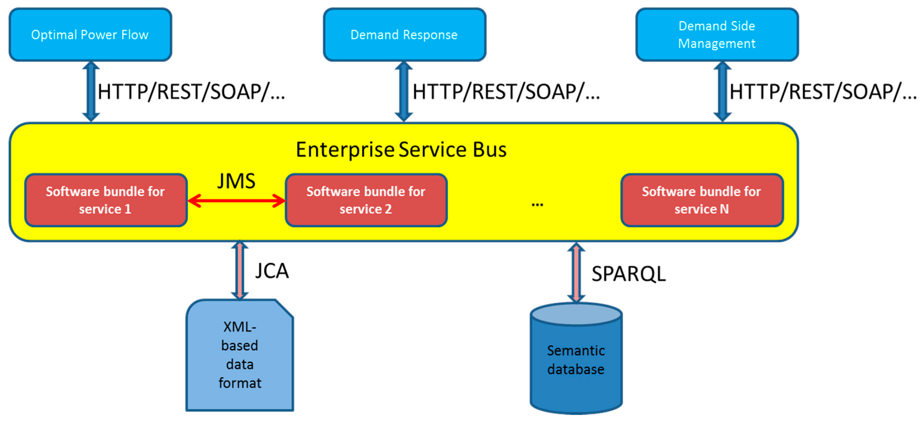
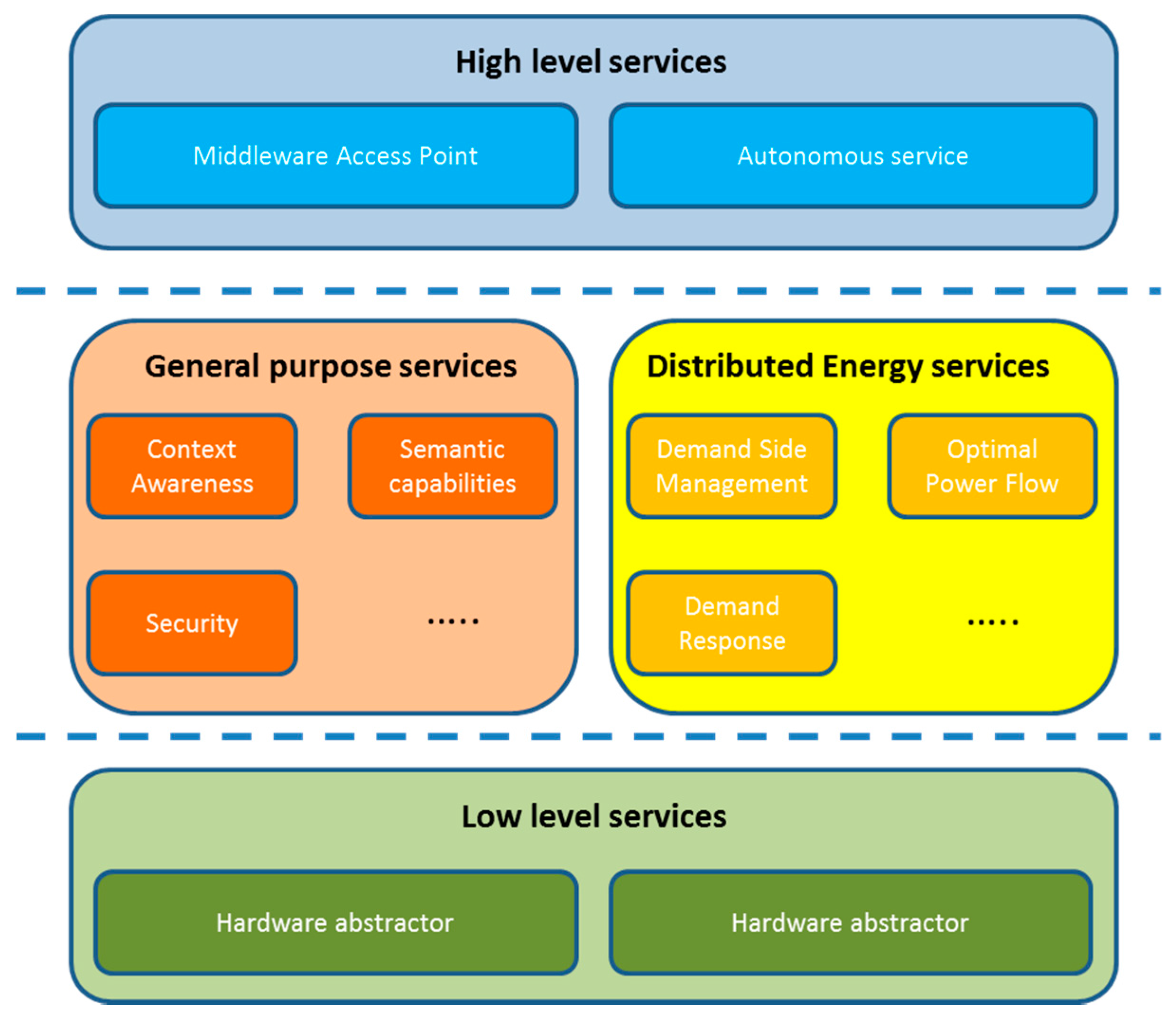
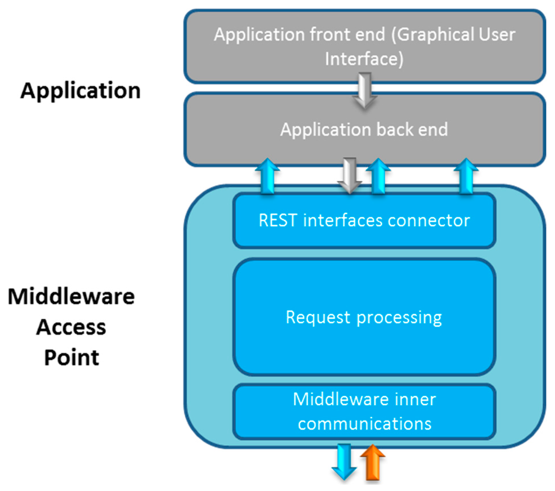

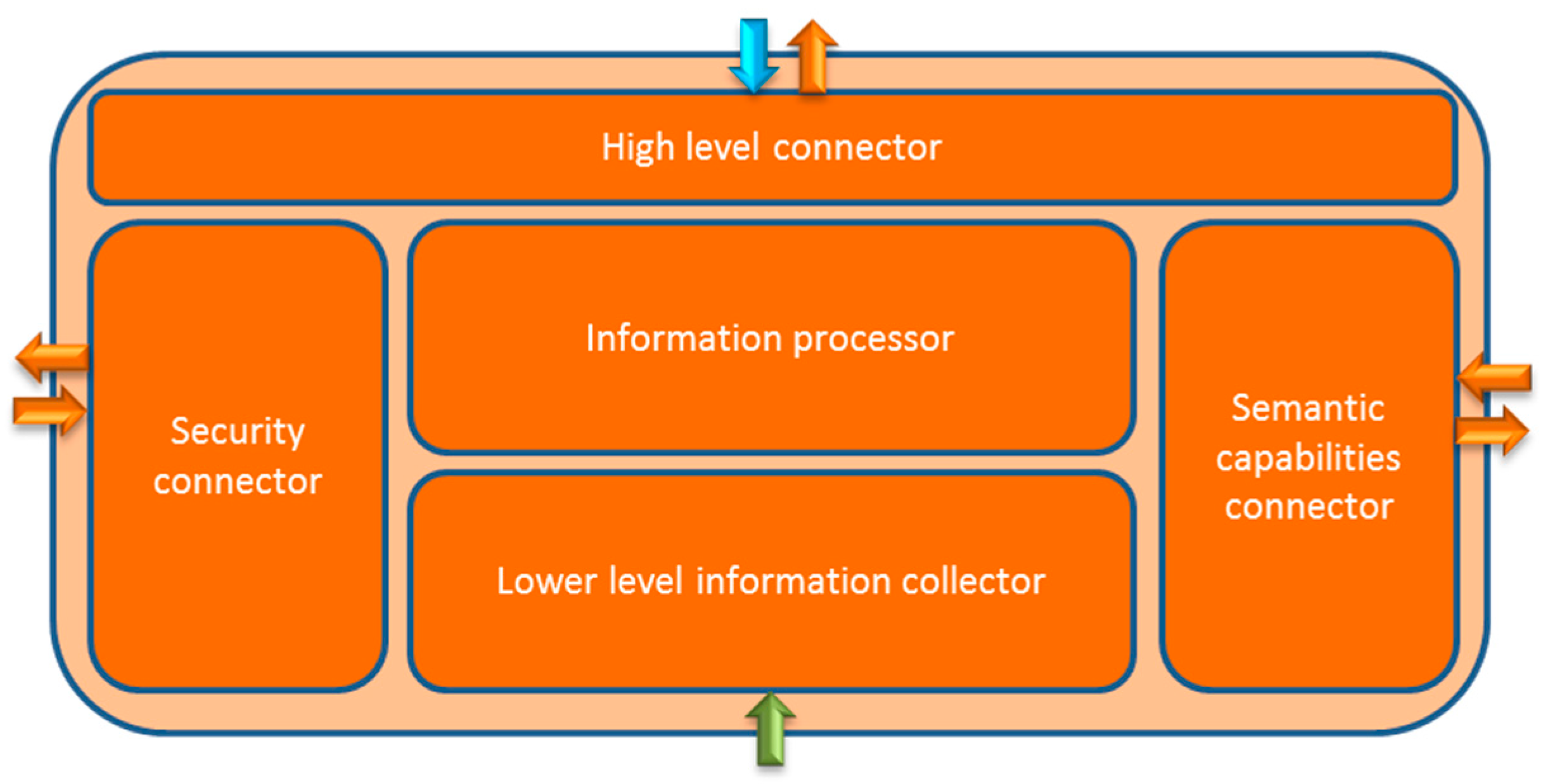
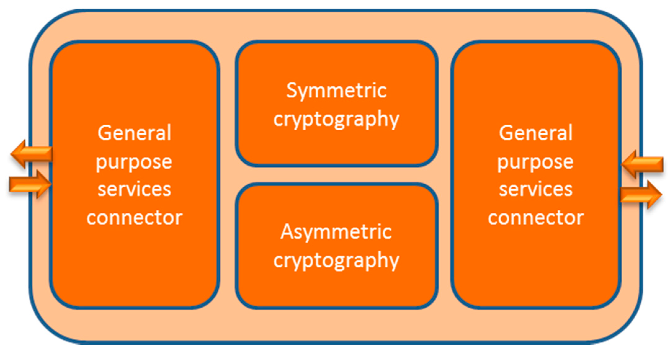
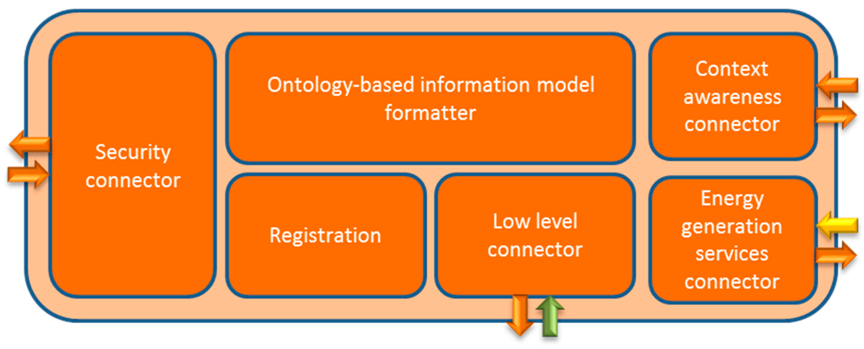
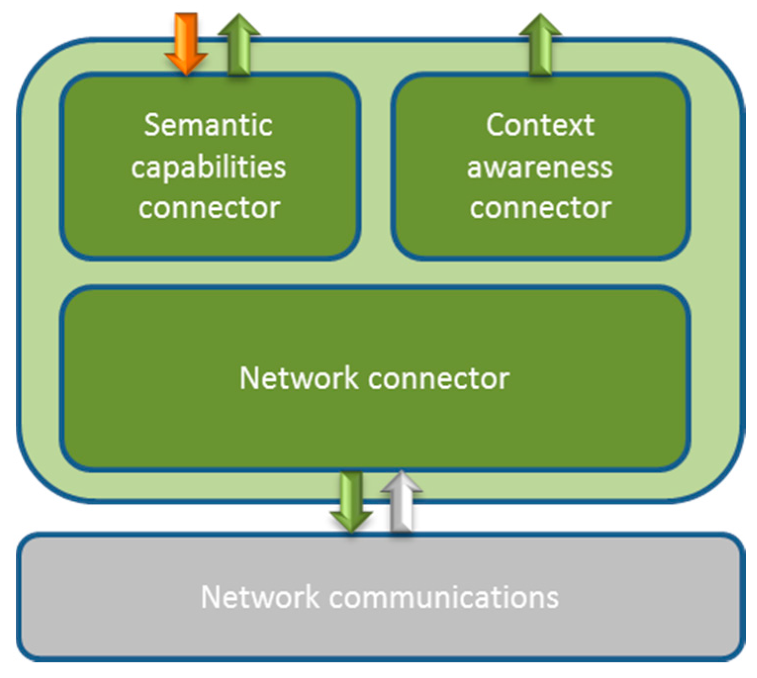

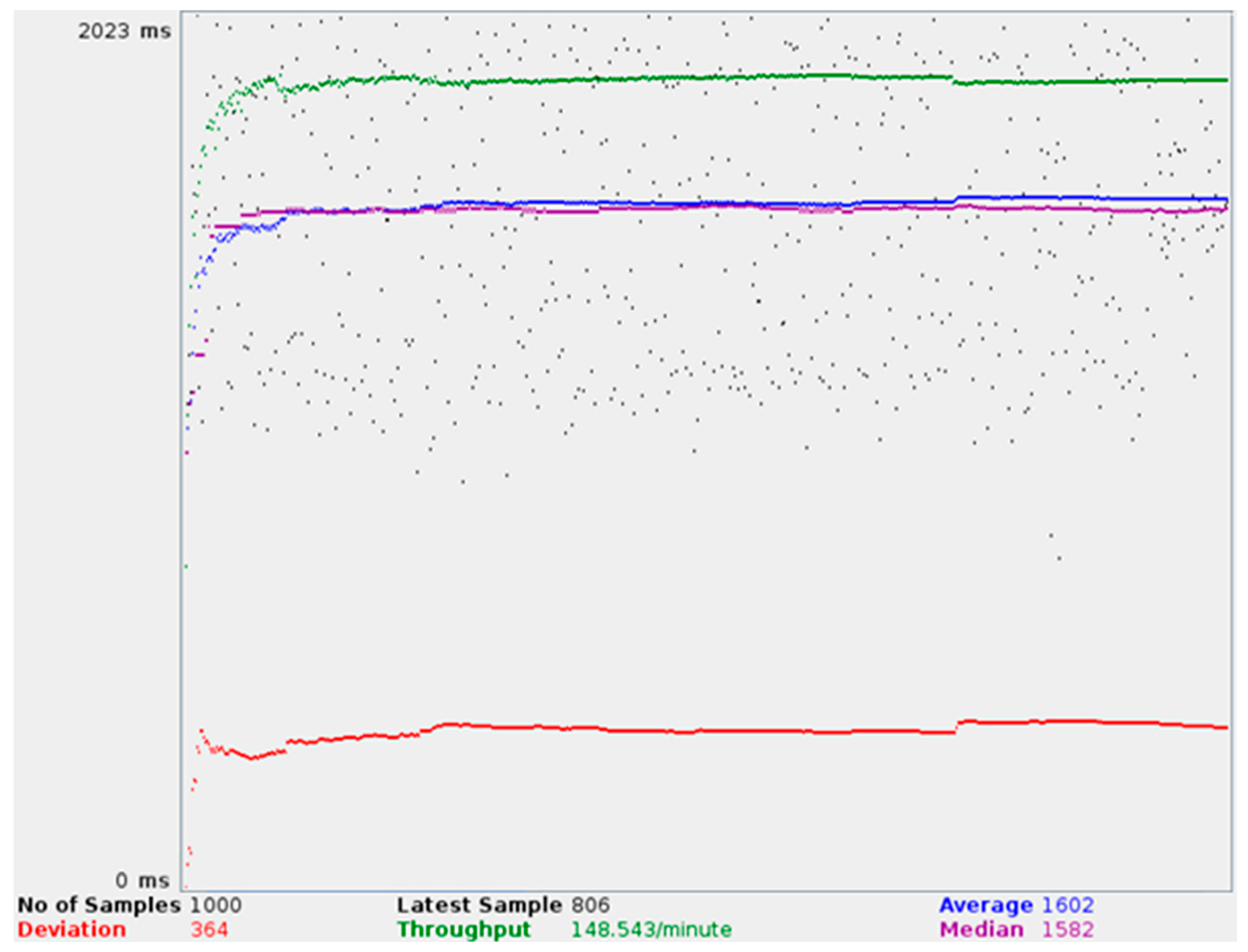

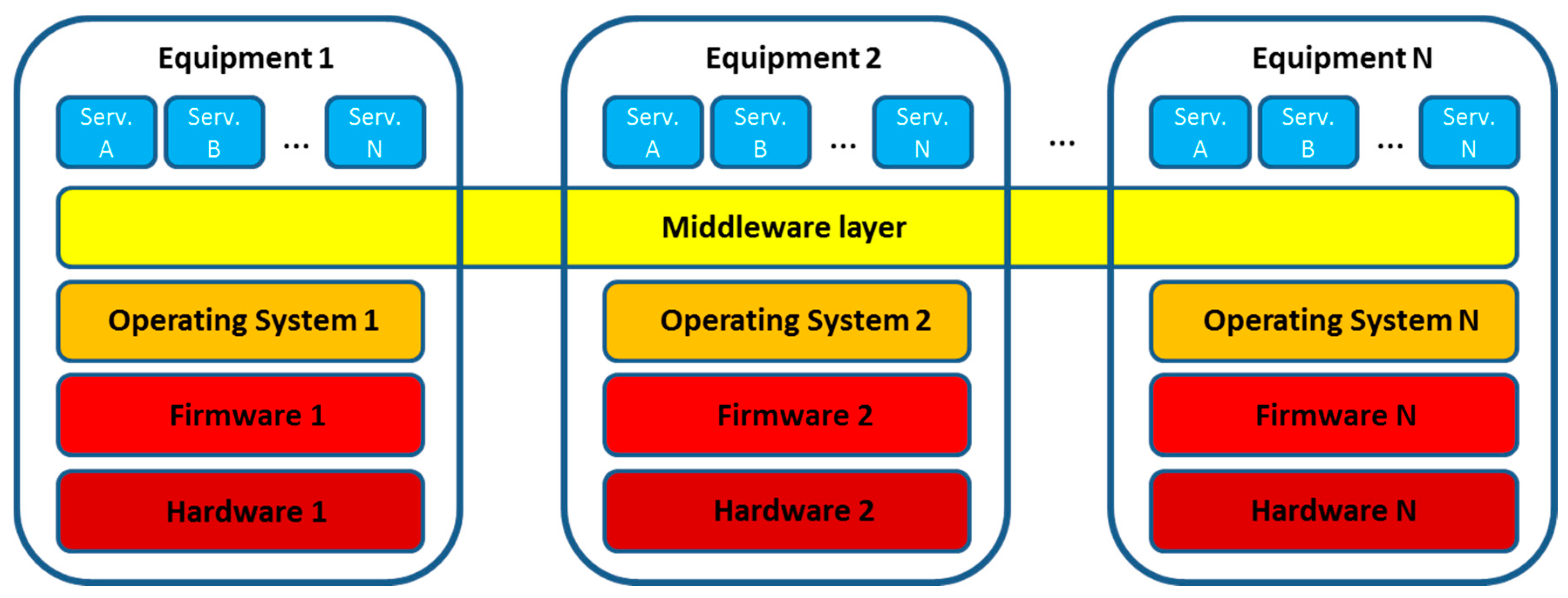
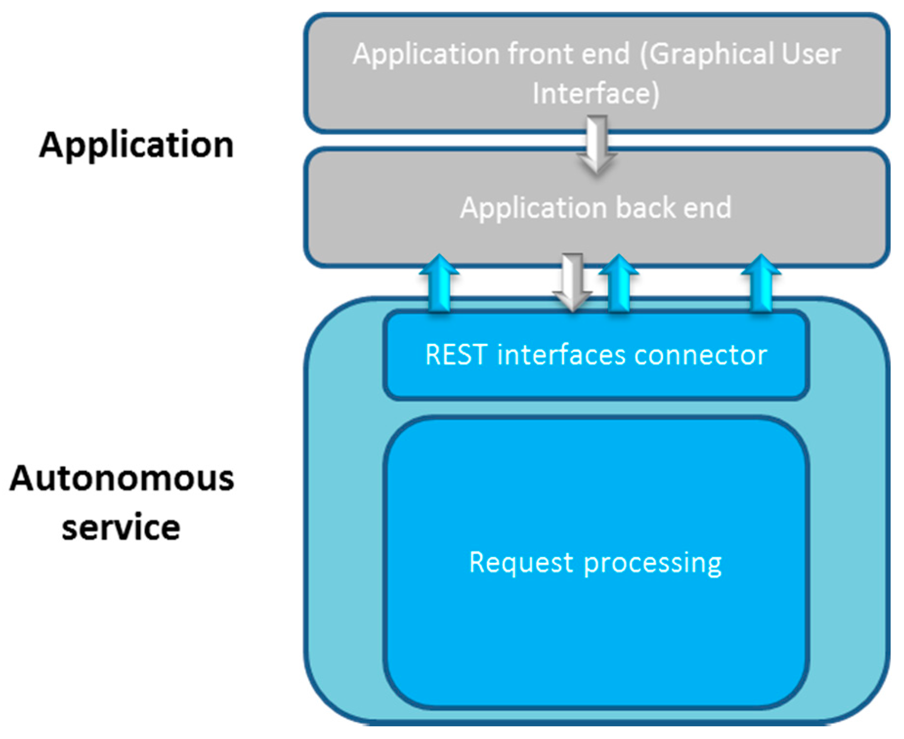
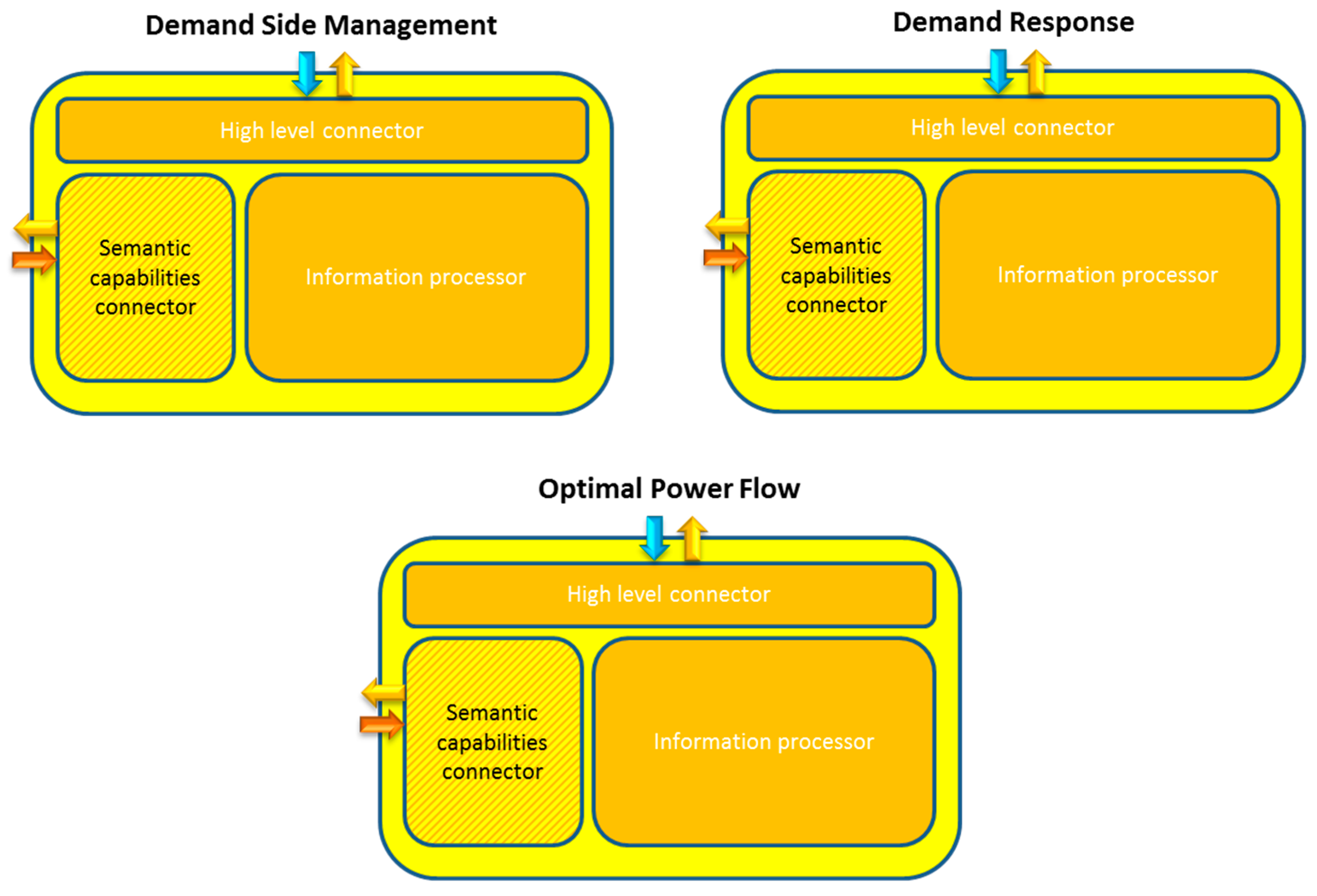
| Generic Challenges | Smart Grid Challenges |
|---|---|
| Devices registration | Registration of PMUs, RTUs, AMIs, etc. |
| Hardware abstraction | Abstraction of PMUs, RTUs, AMIs, etc. |
| Distributed service delivery | Delivery of demand response, demand side management, optimal power flow, etc. |
| System scalability | Usage of ontologies, semantic features. |
| Name | Service Type | Description | Input | Output |
|---|---|---|---|---|
| Autonomous service | High level | Service that is requested from an application that requires no other one in the whole system to deliver the required information | Request made from an application | Data expected to satisfy the former request. It is obtained from the very service that was requested to obtain it. |
| Middleware Access Point | High level | Service that is used to access more complex functionalities that lie either in the middleware architecture or somewhere else (but always at a lower level than high level services) | Request made from an application | Data expected to satisfy the former request. It is obtained from devices or services located in lower levels. |
| Context Awareness | General purpose | Service that is capable of providing information about the surroundings of the system | High level requests regarding system surrounding parameters | Information about context parameters (temperature, power flow values, etc.). Context awareness can also be triggered without previous user requests if an action has to be taken when taking into account parameter values. |
| Security | General purpose | Service that provides security functionalities (confidentiality, data integrity, authentication) | Data transferred through the middleware architecture | Securitized data; either encrypted information or authorized access to the middleware architecture |
| Semantic capabilities | General purpose | Service that enriches the received information by means of ontologies and semantic capabilities | Data received from middleware actions (device registration, device discovery requests, etc.) | Semantically enriched information that might be used to complete registration, information storage, etc. |
| Standardization | General purpose | Service used to adapt the different information formats received in the middleware architecture | Data formatted according to the proprietary solutions existing in the hardware devices | Data formatted according to the choice that has been done regarding middleware format |
| Registration | General purpose | Service used to include information of the available devices and services in a deployment | Device registration request | Either the request is send to the semantic capabilities module or an Acknowledgement is sent to the device that sent the request in the first place |
| Demand Side Management | Distributed energy | Plan to influence the user into adopting long term habits regarding energy consumption | Data regarding energy usage during a comparatively long period of time | Data regarding a plan for energy consumption optimisation in the long term |
| Demand Response | Distributed energy | Plan to influence user to adopt temporary and/or short term measurements for energy saving | Data regarding energy usage during a comparatively short period of time | Data regarding a plan for energy usage in the short term (peak shaving, etc.) |
| Optimal Power Flow | Distributed energy | Description of the best possible way to transmit electricity from one part of the smart grid to another | Data regarding energy consumption in a very short period of time (in a real-time fashion) | Data regarding a plan to optimise the usage of energy |
| Hardware abstractor | Low level | Service used to adapt low level communications (hardware, network layer protocols) | Data received from the network layer | Data sent to the middleware architecture |
| Requirement (Design) | Implementation (Action) |
|---|---|
| Semantic capabilities are required for machine learning and knowledge inference | Development of a semantic module |
| Available hardware components must be registered | Development of a registration module |
| Applications must be able to access the middleware architecture | Development of Application Access Points |
| Hardware components must be able to access the middleware architecture | Development of modules with low level interfaces |
| Data confidentiality, integrity, and authentication must be provided in the deployed system | Development of security capabilities |
| Step | Input | Output |
|---|---|---|
| Obtaining an open source Enterprise Service Bus | Machines with a functional operating system | Open source Enterprise Service Bus installed and running with the default components |
| Development of middleware protocol or message collection | Collection of data and/or information that is going to be sent through the middleware architecture and the overall system | Messaging system that is going to be used for the common information model employed in the architecture, either taken from an already existing standard or tailored from scratch |
| Development of software bundles | Open source Enterprise Service Bus installed and running with the default components | Software services developed according to the reference architecture provided |
| Interconnectivity of software bundles | Software services developed according to the reference architecture provided | Software bundles cooperating with each other in order to deliver functionalities and services |
| Messaging system that is going to be used for the common information model employed in the architecture | ||
| High level interfaces | Software bundles cooperating with each other in order to deliver functionalities and services | Application-related interfaces capable of sending messages throughout tall the middleware inner layers and components |
| Low level interfaces | Application-related interfaces capable of sending messages throughout tall the middleware inner layers and components | Network and hardware-related interfaces able to send and receive messages from outer devices |
| Securitization procedures | Testing of all the functionalities is done so that their actual performance is checked | The final version of the middleware solution added to the smart grid is tested. Any minor bug is fixed |
© 2017 by the authors. Licensee MDPI, Basel, Switzerland. This article is an open access article distributed under the terms and conditions of the Creative Commons Attribution (CC BY) license ( http://creativecommons.org/licenses/by/4.0/).
Share and Cite
Rodríguez-Molina, J.; Martínez, J.-F.; Castillejo, P.; Rubio, G. Development of Middleware Applied to Microgrids by Means of an Open Source Enterprise Service Bus. Energies 2017, 10, 172. https://doi.org/10.3390/en10020172
Rodríguez-Molina J, Martínez J-F, Castillejo P, Rubio G. Development of Middleware Applied to Microgrids by Means of an Open Source Enterprise Service Bus. Energies. 2017; 10(2):172. https://doi.org/10.3390/en10020172
Chicago/Turabian StyleRodríguez-Molina, Jesús, José-Fernán Martínez, Pedro Castillejo, and Gregorio Rubio. 2017. "Development of Middleware Applied to Microgrids by Means of an Open Source Enterprise Service Bus" Energies 10, no. 2: 172. https://doi.org/10.3390/en10020172