Article

Mode Shift Control for a Hybrid Heavy-Duty Vehicle with Power-Split Transmission

1
National Key Laboratory of Vehicle Transmission, Beijing Institute of Technology, Beijing 100081, China
2
Department of Mechanical Engineering, Texas A&M University, College Station, TX 77843, USA
*
Authors to whom correspondence should be addressed.
Energies 2017, 10(2), 177; https://doi.org/10.3390/en10020177
Submission received: 15 December 2016 / Revised: 24 January 2017 / Accepted: 24 January 2017 / Published: 4 February 2017

Abstract

:
Given that power-split transmission (PST) is considered to be a major powertrain technology for hybrid heavy-duty vehicles (HDVs), the development and application of PST in the HDVs make mode shift control an essential aspect of powertrain system design. This paper presents a shift schedule design and torque control strategy for a hybrid HDV with PST during mode shift, intended to reduce the output torque variation and improve the shift quality (SQ). Firstly, detailed dynamic models of the hybrid HDV are developed to analyze the mode shift characteristics. Then, a gear shift schedule calculation method including a dynamic shift schedule and an economic shift schedule is provided. Based on the dynamic models and the designed shift schedule, a mode shift performance simulator is built using MATLAB/Simulink, and simulations are carried out. Through analysis of the dynamic equations, it is seen that the inertia torques of the motor–generator lead to the occurrence of transition torque. To avoid the unwanted transition torque, we use a mode shift control strategy that coordinates the motor–generator torque to compensate for the transition torque. The simulation and experimental results demonstrate that the output torque variation during mode shift is effectively reduced by the proposed control strategy, thereby improving the SQ.

Graphical Abstract

1. Introduction

Generally, a power-split hybrid electric vehicle (HEV) distributes the driving power through one engine and two motor-generators (MGs) coupled with a power-split transmission (PST) [1,2,3]. When operating a power-split HEV, the planetary gear (PG) sets serve as a PST that transfers the engine power to the vehicle through the mechanical path and the electrical path, as shown in Figure 1. The mechanical path directly transmits the power from the PST to the wheels. The rest of the engine power is transferred by the electrical path and is then transformed into electricity through the generator; next, this power is either sent to the motor or stored in the battery. Because the engine is independent of the wheels, therefore, it enables the engine to operate in its best efficiency region and provide better fuel economy, which also means an electronically controlled continuously variable transmission (ECVT). Moreover, MGs can coordinate engine starting and stopping while the vehicle is running [4,5].
Furthermore, PST combines with a relatively small number of frictional elements, including clutch and brake, such that the transmission enables the vehicle at high efficiencies and meets the special requirements of the hybrid heavy-duty vehicle (HDV), such as wide speed range and large power of the MGs [6,7]. In this regard, the application of the hybrid HDV with PST is readily adaptable to the commercial market and the agricultural market, such as a bulldozer or a heavy truck for mining. Given the excellent characteristics of the power-split HEV, to explore and develop the analysis method, design theory, and control strategy of such a system, previous research studies on the power-split HEV have put forward different operating strategies in terms of fuel consumption by a neural network [8], rule-based supervisory control [9], optimal control [10], multi-input fuzzy logic controller [11], multivariable coordination controller [12], quadratic programming [13], and nonlinear model predictive control [14].
Shift schedule design, as a rule-based strategy to judge the suitable operating mode based on the driver’s demand and the vehicle speed, has a great impact on the vehicle’s economic and dynamic performance [15]. Shift schedule designs for conventional vehicles are well developed, including the detailed calculation method [16] and the graphical method of gear shifts [17]. However, few references propose systematic methods to design shift schedule for HEVs. Existing solutions found in the literature are based on heuristic techniques and engineering experiences, such as using the throttle opening and vehicle speed as reference parameters [18,19,20,21]. Due to the high coupling of the power sources in the power-split HEVs, the characteristics and efficiency of the MGs and battery will result in different results from those of conventional vehicles. In this regard, it is necessary to establish appropriate shift schedules for power-split HEVs on the basis of the conventional gear shift schedule, providing the theory to support power-split HEVs matching and optimization.
On the other hand, by changing the clutch/brake states, the power-split HEV can achieve different operating modes (input-split, output-split and compound-split, etc.). To make full use of the PST topology, mode shift, as a significant phase among these different operating modes, is necessary to maintain the vehicle stability and optimize the vehicle operation. However, an inappropriate mode shift, if improperly managed, might deteriorate the vehicle’s shift quality (SQ). This reduced SQ is caused by the occurrence of torque interruption, when the clutch (brake) is improperly engaged during mode shift. Previous researches on the transition state of power-split HEV have investigated optimal control design for a vehicle equipped with a dual-clutch transmission [22], model predictive control method applied to regulate the clutch torque [23], slipping-speed control approach of the clutch [24], robust controller based on the mu-synthesis [25], adaptive control proposed for the clutch-to-clutch shift [26], model referenced control [27], and dynamic coordinated control strategy [28,29]. To improve the SQ, a motor torque control is applied for a power-split HEV [30]. However, in this study, only the designer’s experience was considered to propose the motor torque control, and the theoretical analysis was neglected.
The objective of this paper is to establish a shift schedule graphical design method, which includes a dynamic shift schedule and an economic shift schedule, and propose a torque control strategy with theoretical analysis to reduce the transient torque interruption for a hybrid HDV with PST during mode shift. The structure of this paper is organized as follows: following the introduction, Section 2 concerns the modeling of the hybrid HDV with PST. Section 3 introduces the shift schedule design, including dynamic shift schedule and economic shift schedule. Section 4 analyzes the mode shift performance and provides a theoretical method to design an MG torque control strategy. Section 5 evaluates the performance of the proposed control strategy by simulation comparison and experimentally validates the effectiveness of the proposed control strategy by a bench test of the hybrid HDV. Section 6 presents the conclusions of the study.

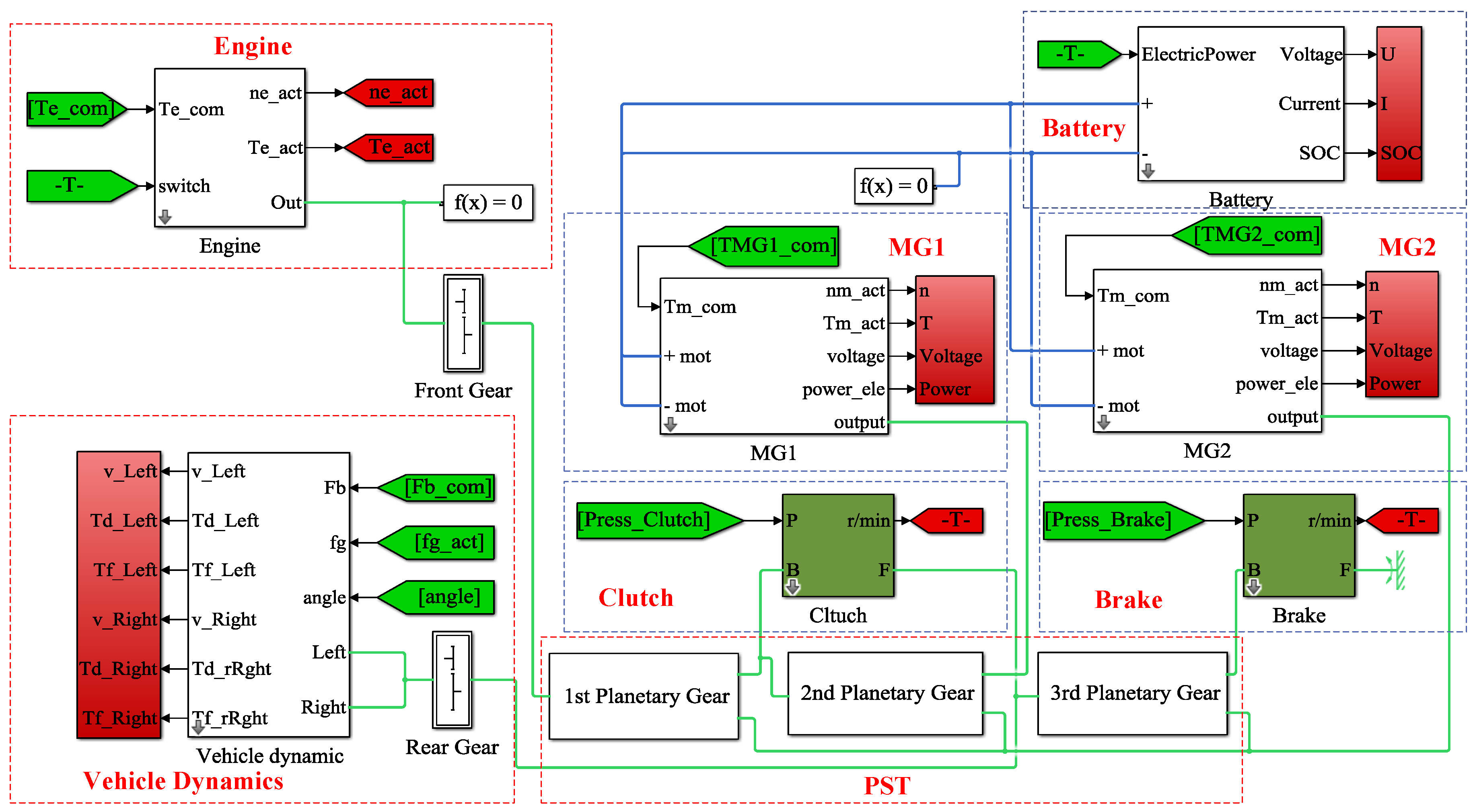
2. Modeling of Hybrid Heavy-Duty Vehicle

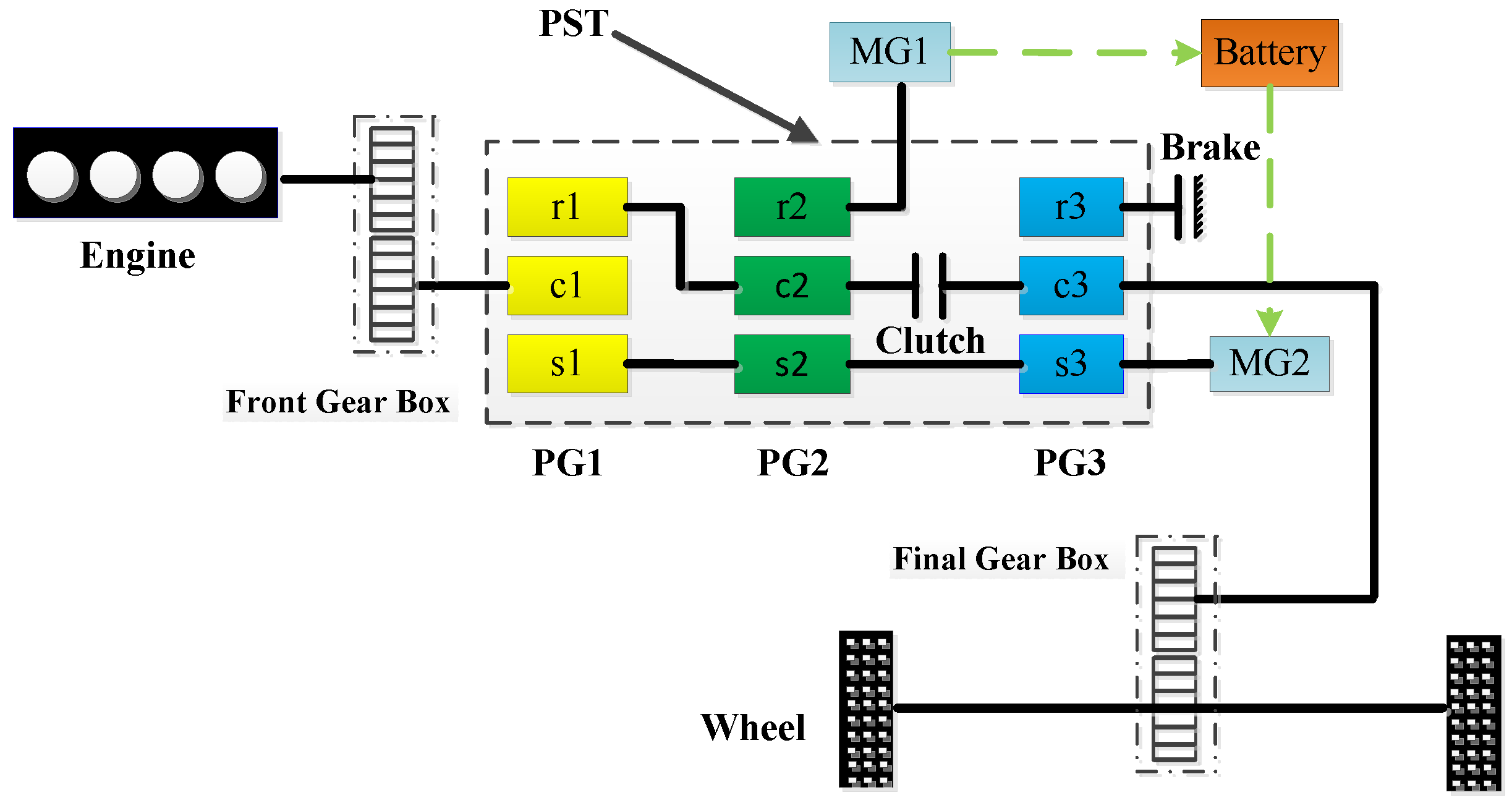
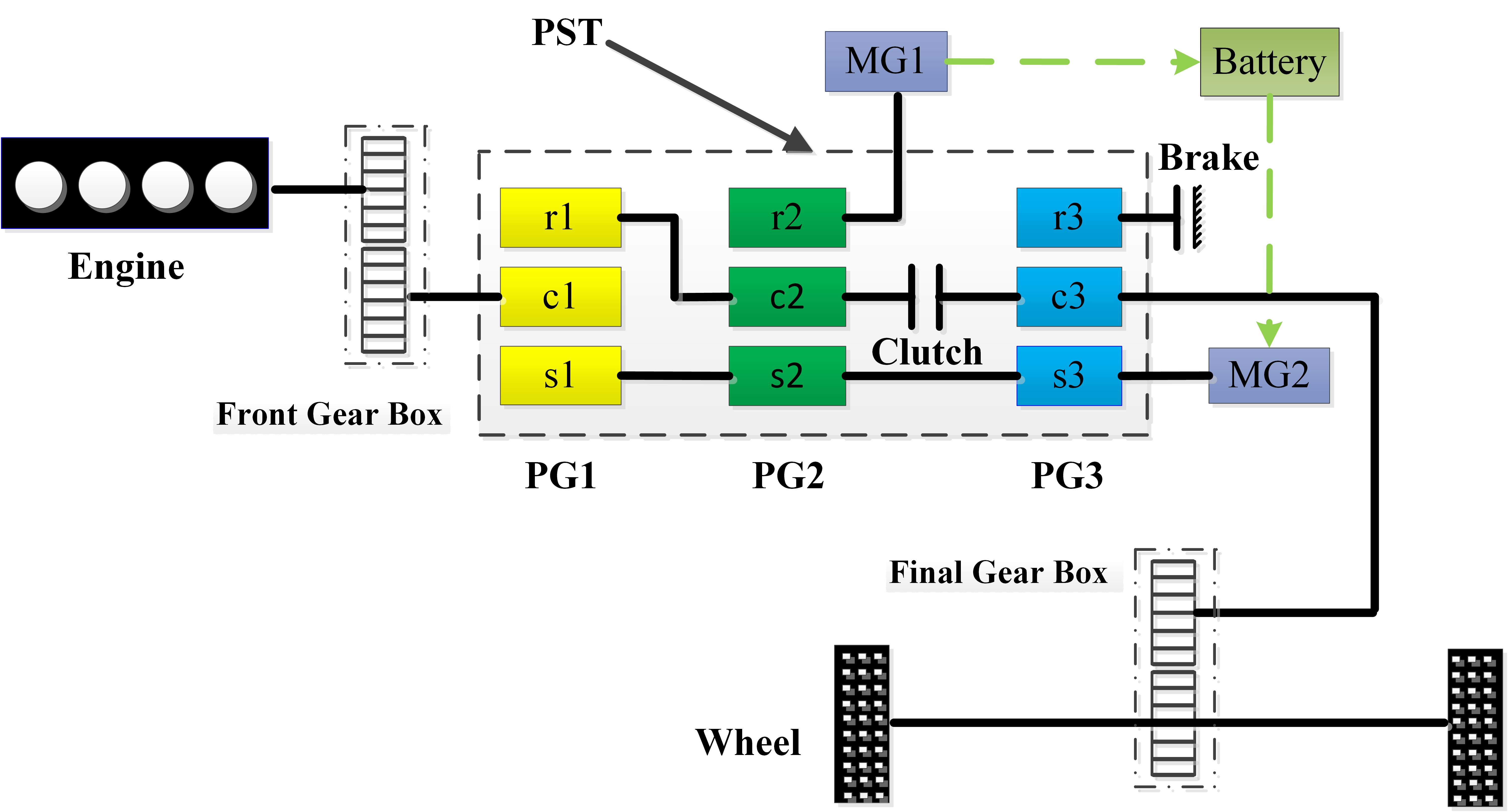
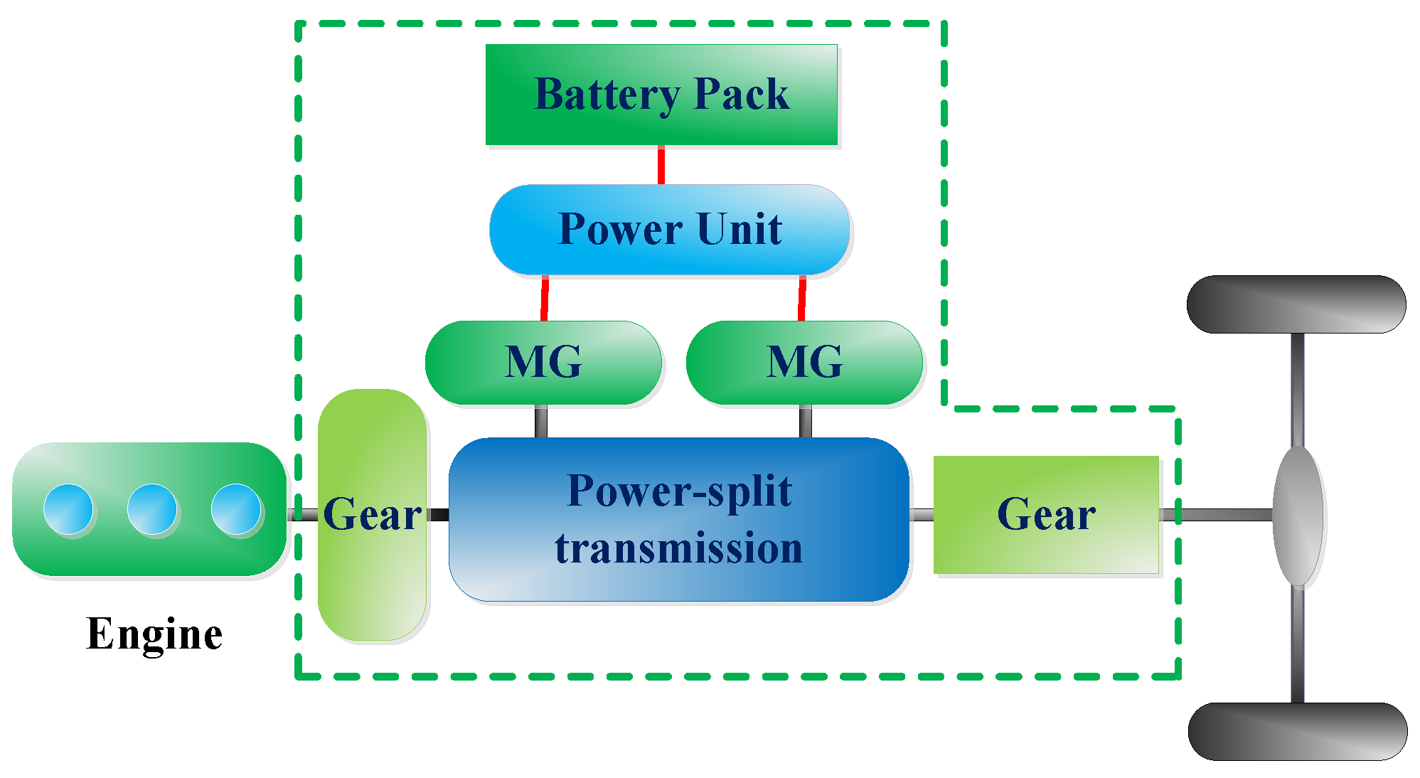
2.1. Introduction to the Hybrid Heavy-Duty Vehicle

Figure 2 depicts the overall layout of the hybrid HDV with PST, which mainly consists of three planetary gears (PGs), two MGs, one clutch, one brake and a battery pack. The three PGs are used by the hybrid HDV as a PST. The PG consists of a sun gear, a ring gear, and a carrier gear that carries a set of small gears called pinion gears; Figure 3 shows the PG and its level diagram analogy. The PST provides the interconnection between the engine and MGs. As shown in Figure 2, it can be seen that the engine is engaged to the carrier gear of PG1 and that MG1 is connected to the ring gear of PG2. The sun gear and the ring gear of PG1 are connected to the sun gear and the carrier of PG2, respectively. In addition, MG2 is connected to the sun gear of PG3 and the output shaft is connected to the carrier of PG3.
The HDV can provide two electrically variable transmission (EVT) modes by operating the MGs and the clutch (brake). The EVT modes consist of the input-split mode (EVT Mode 1) and the compound-split mode (EVT Mode 2), as presented in Table 1. When the clutch is disengaged (and the brake is engaged), the vehicle is operated in the EVT Mode 1. In this case, MG1 is used as a generator and MG2 behaves as a motor; that is, MG2 generates positive torque to propel the vehicle running, which can positively regulate the engine operation to the optimal operation line, and the electrical power generated by MG1 is transmitted to MG2 or stored in the battery. On the other hand, when the clutch is engaged (and the brake is disengaged), MG1 is used as a motor and MG2 behaves as a generator; this case defines the EVT Mode 2. This means that MG1 is applied to maintain the engine optimal operation points, and the electrical power from MG2 is supplied to MG1 and the battery. It is obvious that the mode shift from EVT 1 mode to EVT 2 mode is a critical and necessary process to transfer power sources among the engine, MGs, and battery pack.

2.2. Problem Formulation

In this paper, shift schedule, as a critical aspect of mode shift, decides whether the investigated hybrid HDV shifts on the best shift point and determines the exerting potential of the vehicle’s economic and dynamic performance. Since the hybrid HDV with PST is very different from conventional vehicles, it is therefore necessary to consider the following key factors when designing a shift schedule: (1) the working state of the MGs; (2) the driving efficiency; and (3) the state of charge (SOC) of the battery. In addition, mode shift is realized by engaging and disengaging the clutch (brake). In this scenario, the main challenges lie in the following issues. The first issue is the occurrence of an inappropriate mode shift due to unwanted output torque variation, which deteriorates the vehicle’s SQ. This reduced SQ is due to the improper engagement of the clutch (brake) during mode shift. Another issue is that sometimes it is necessary to control the MGs’ torque to reduce the output torque variation during mode shift. Briefly, it is necessary to propose a proper control strategy that involves coordinating engine, the MGs and the clutch (brake) to solve the above-described issues, and ultimately to improve SQ.

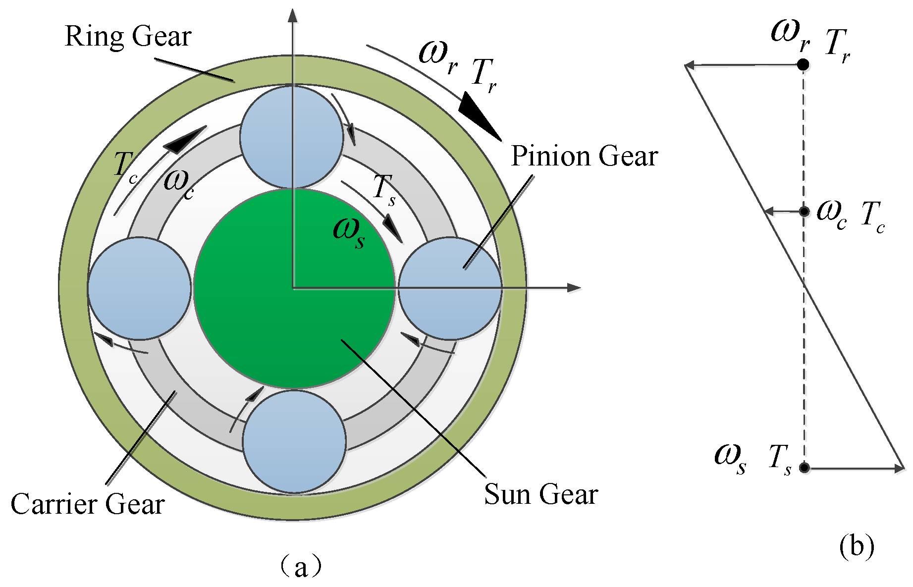
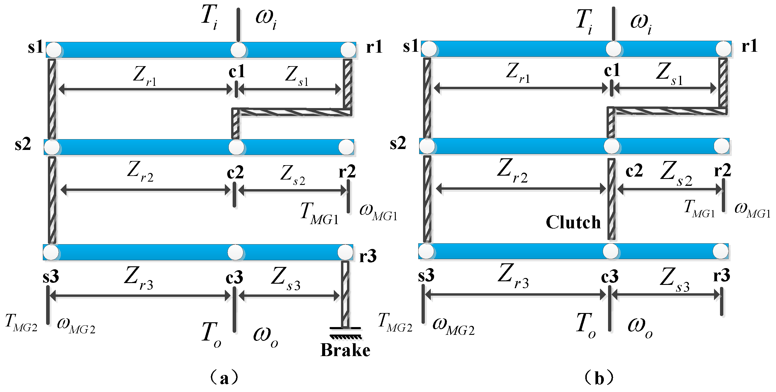
2.3. Speed Equations and Torque Equations

To analyze the hybrid HDV with PST, the state equations between the engine, MGs, and the driveshaft should be derived. As a result of the mechanical connections made through the gear teeth, the speed and the torque relationships between the sun gear, the ring gear, and the carrier gear can be expressed as follows [6]:
Z s ω s + Z r ω r = ( Z s + Z r ) ω c
T s : T r : T c = 1 : ( Z r / Z s ) : ( ( 1 + Z r / Z s ) )
where Z s and Z r are the teeth number of the sun gear and the ring gear, ω is the gear rotational speed, T is the gear torque, subscript r denotes ring gear, subscript s denotes sun gear, and subscript c denotes carrier gear.
The steady-state model of PGs can be derived from a lever diagram, as shown in Figure 4. Therefore, the speed and the torque relationships of EVT Mode 1 based on Figure 4a can be written as follows [7,14]:
ω M G 1 = ( 1 + K 1 ) ( 1 + K 2 ) K 1 K 2 ω i ( 1 + K 3 ) ( 1 + K 1 + K 2 ) K 1 K 2 ω o
ω M G 2   =   ( 1 + K 3 ) ω o
T i = ( 1 + K 1 ) ( 1 + K 2 ) K 1 K 2 T M G 1
T o = ( 1 + K 1 + K 2 ) ( 1 + K 3 ) ( 1 + K 1 ) ( 1 + K 2 ) T M G 1 + ( 1 + K 3 ) T M G 2
T i = T e i i ; ω i = ω e / i i
where subscript 1 denotes PG1, subscript 2 denotes PG2, subscript 3 denotes PG3; ω e , ω i , ω M G 1 , ω M G 2 and ω o are the engine speed, the input speed, the MG1 speed, the MG2 speed and the output speed, respectively; T e , T i , T M G 1 , T M G 2 and T o u t are the engine torque, the input torque, the MG1 torque, the MG2 torque and the output torque, respectively. Note that i i is the gear ratio of the front gearbox, K 1 = Z r 1 / Z s 1 , K 2 = Z r 2 / Z s 2 and K 3 = Z r 3 / Z s 3 .
Figure 4b is the lever diagram of the hybrid HDV with PST for EVT Mode 2. Similar to EVT Mode 1, the speed and the torque relationships of EVT Mode 2 are as follows:
ω M G 1 = 1 + K 2 K 1 ω i + 1 + K 1 + K 2 K 1 ω o
ω M G 2 = ( 1 + K 2 ) ω i K 2 ω o
T i = 1 + K 2 K 1 T M G 1 ( 1 + K 2 ) T M G 2
T o = 1 + K 1 + K 2 K 1 T M G 1 K 2 T M G 2 .

2.4. Dynamic Equations
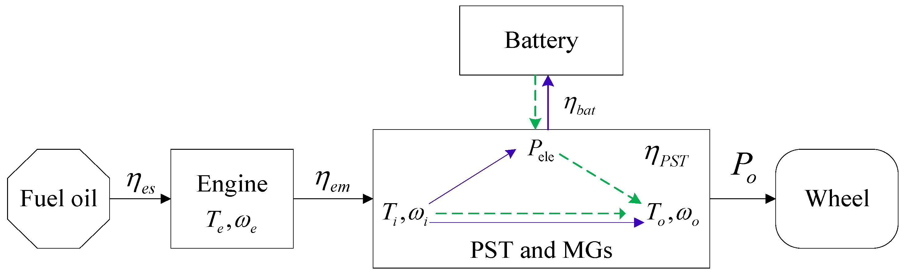
To simplify the dynamic model of the hybrid HDV with PST, it is assumed that the inertia of the pinion gears in the PGs is neglected and all the connecting shafts of the powertrain system are rigid. Therefore, the dynamic equations can be written as follows [6]:
( J i + J c 1 ) ω ˙ i = T i T c 1
( J M G 1 + J r 2 ) ω ˙ M G 1 = T M G 1 T r 2
( J M G 2 + J s 1 + J s 2 + J s 3 ) ω ˙ M G 2 = T M G 2 T s 1 T s 2 T s 3
( J o + J c 3 ) ω ˙ o = T o T f
( J r 1 + J c 2 ) ω ˙ c 2 = T r 1 + T c 2 ,
where J i , J M G 1 , J M G 2 , J o are the moment inertias of the input shaft, MG1, MG2 and the output shaft, respectively. J s i , J r i , J c i ( i = 1 , 2 , 3 ) are the moment inertias of the sun gear, the ring gear and the carrier gear of each PG, respectively. T s i , T r i , T c i ( i = 1 , 2 , 3 ) are the sun gear torque, the ring gear torque and the carrier gear torque of each PG, respectively.

2.5. Engine Model

The engine, as the main power source, plays an increasingly important role in the hybrid HDV [31]. Because the engine is a time-varying nonlinear system that is comparatively complex in structure and internal variables, an accurate model is difficult to build. However, the engine experimental model can be used with experimental data collected for the dynamic characteristics of the engine, therefore, the engine model is simplified as a first-order transfer function that can be expressed as [1]:
T e = 1 τ e s + 1 T e _ d e s i r e d
T e _ d e s i r e d = f ( ω e , α )
where α is the engine throttle opening, f is a function of the engine speed and throttle opening, used to describe the interconnection between engine characteristics and the desired engine torque T e _ d e s i r e d , and τ e is a time constant of the first-order transfer function.

2.6. Motor-Generator Model

When the power flows out from the MG to the battery, the MG operates as a motor; when the power flows in from the battery to the MG, the MG is used as a generator. In this paper, the MG is modeled by its efficiency characteristic, and the MG efficiency can be described as a function of the MG speed and the torque. The MG power can be expressed by the mechanical power, the electrical power, and the power loss as [14]:
P e l e c = P m e c h + P l o s s
where P m e c h , P e l e c , P l o s s are the mechanical power, the electrical power and the power loss, respectively. When P e l e c > P m e c h , the MG is used as a motor; when P e l e c < P m e c h , the MG operates as a generator. The MG torque can be determined as:
T M G = V b a t I b a t P l o s s ω M G
where V b a t , I b a t are the battery voltage and current, respectively.

2.7. Battery Model

The battery pack, as an additional power source, is an essential energy storage unit of the hybrid HDV, and the power to or from the battery pack is related to the power required by the MG and the other accessories [32,33]. In addition, the battery pack can be charged and discharged in real time, based on the vehicle’s driving conditions.
The battery pack model is an equivalent circuit with an internal resistance, and the battery pack’s internal resistance can be obtained from the experimental data, as shown in Figure 5. The equivalent circuit and SOC of the battery can be given by the following equations [7]:
V b a t = U o c R b a t I b a t
S O C b a t = S O C o η P b a t C b a t V b a t d t
where U o c is the open-circuit voltage of the battery, R b a t is the internal resistance of the battery, S O C o is the initial state-of-charge, η is the charge-discharge efficiency, P b a t is the battery power, and C b a t is the capacity of the battery.

2.8. Clutch/Brake Model

Clutch/brake is an essential operational component of the hybrid HDV during mode shift to connect the powertrain system, or transfer the driving power to maintain the vehicle running. Basically, the engagement process of the clutch consists of three phases, namely, open phase, slipping phase, and locked phase, according to [27]:
T c = { 0 ( open ) Z μ d 2 3 R o 3 R i 3 R o 2 R i 2 P A p sgn ( ω i n ω o u t ) ( slipping ) Z μ s 2 3 R o 3 R i 3 R o 2 R i 2 P A p ( locked )
where T c is the clutch frictional torque, Z is the number of clutch plate, R o is the outside radius of the clutch plate, R i is the inside radius of the clutch plate, P is the hydraulic pressure of the clutch, A p is the clutch piston area, μ d is the dynamic friction coefficient of the clutch, μ s is the static friction coefficient of the clutch, ω i n is the input-side speed of the clutch, and ω o u t is the output-side speed of the clutch. Note that the difference value between ω i n and ω o u t is referred to as the speed difference of the clutch Δ ω c l , and can be obtained as follows:
Δ ω c l = | K 2 ( 1 + K 3 ) ω M G 1 + ( K 3 K 1 ) ω M G 2 ( 1 + K 2 ) ( 1 + K 3 ) |

2.9. Vehicle Dynamics

The vehicle dynamics equation can be written as [14]:
M V ˙ = T o [ 1 2 ρ C d A V 2 + C r M gcos ( θ ) + M gsin ( θ ) ]
T f = 1 2 ρ C d A V 2 + C r M gcos ( θ ) + M gsin ( θ )
where M is the vehicle mass, V is the vehicle speed, T f is the road load torque, ρ is the air density, C d is the drag coefficient, A is the frontal area of the vehicle, C r is the rolling resistance coefficient, g is the gravity acceleration, and θ is the road grade. Table 2 presents the main parameters of the hybrid HDV with PST in this paper.

3. Shift Schedule Design of Hybrid Heavy-Duty Vehicle

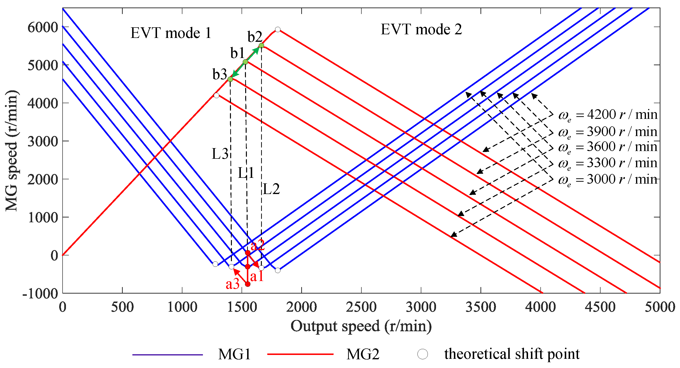
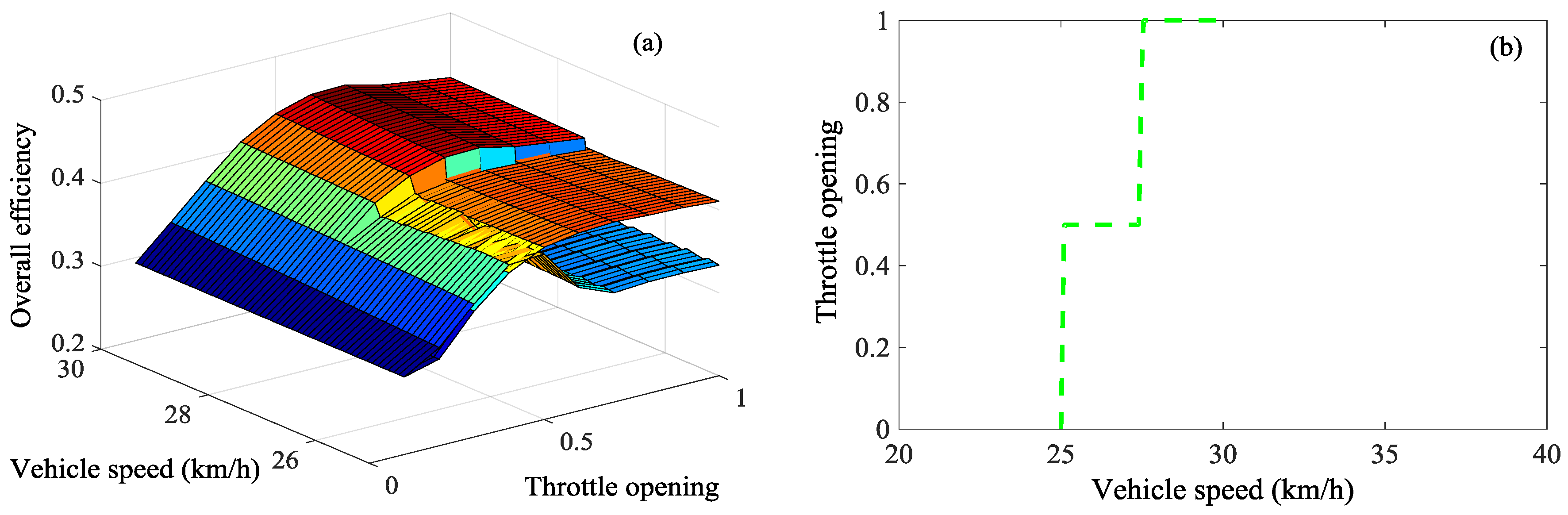
3.1. Shift Point Analysis

Using the speed–torque equations that were previously derived for the hybrid HDV by mode, the theoretical shift point can be analyzed. In the analysis, it is assumed that the value of the engine speed is constant, and the clutch/brake engagement is smooth and unbuffered during mode shift. Figure 6 shows the analysis of theoretical shift point for the hybrid HDV with respect to the different engine speeds. It is seen that when the vehicle enters EVT Mode 1, the MG1 speed is monotonically decreasing and continuous function (as a generator) and the MG2 speed is monotonically increasing and continuous function (as a motor); when the vehicle shifts to EVT Mode 2, the MG1 speed is monotonically increasing function (as a motor) and the MG2 speed is monotonically decreasing function (as a generator).
On the other hand, it is difficult to maintain the engine speed in real driving conditions; therefore, the variation of the engine speed can lead to a change of the theoretical shift point. For example, when the engine speed suddenly increases from 3600 r/min to 3900 r/min, the theoretical shift point moves from L1 to L2, the MG1 speed changes from a1 to a2 and then along the new speed curve, while the MG2 speed changes along the curve b1 to b2; when the engine speed suddenly decreases from 3600 r/min to 3300 r/min, the theoretical shift point moves from L1 to L3, the MG1 speed changes from a1 to a3 and then along the new speed curve, while the MG2 speed changes along the curve b1–b3.
Generally, there exists a certain deviation between the actual shift point and the theoretical shift point for the hybrid HDV. The existing deviation has a direct impact on the speed difference of the clutch/brake when engaging during mode shift. As mentioned in Section 2.2, the output torque variation due to the clutch/brake engagement during mode shift can decrease the SQ. That is, the deviation of the shift point also influences the vehicle’s driving comfort; therefore, it is necessary to design a proper shift schedule and choose the best shift point for the hybrid HDV during mode shift.

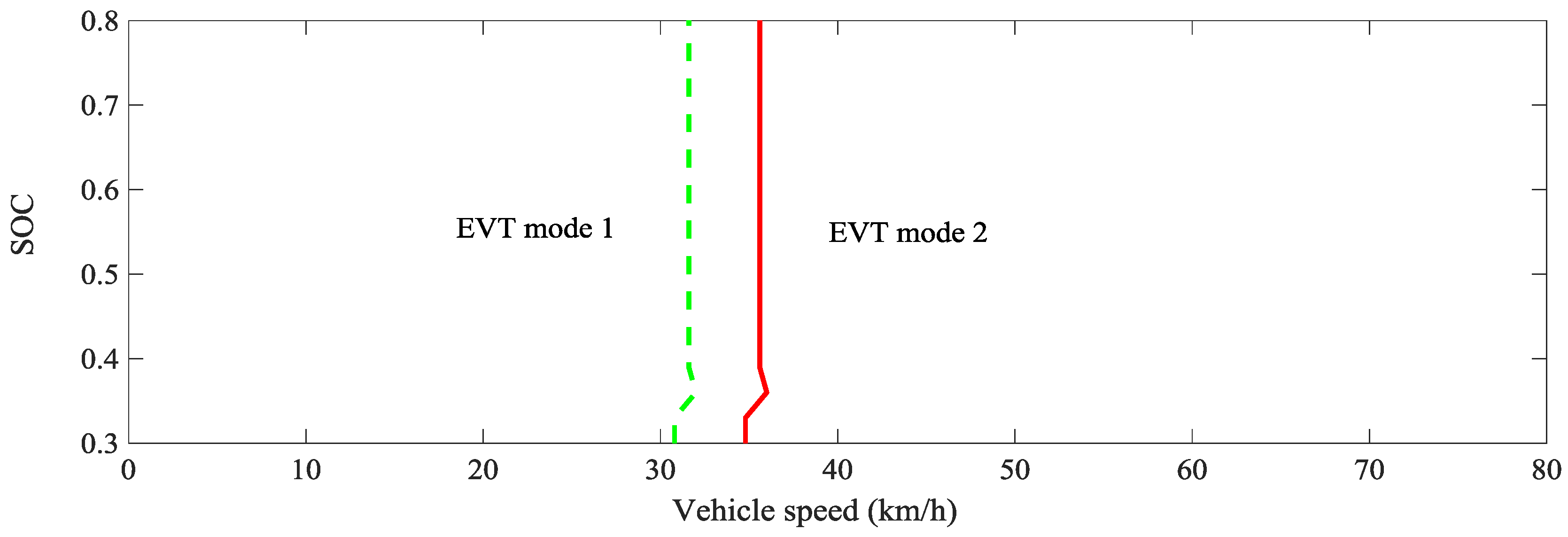
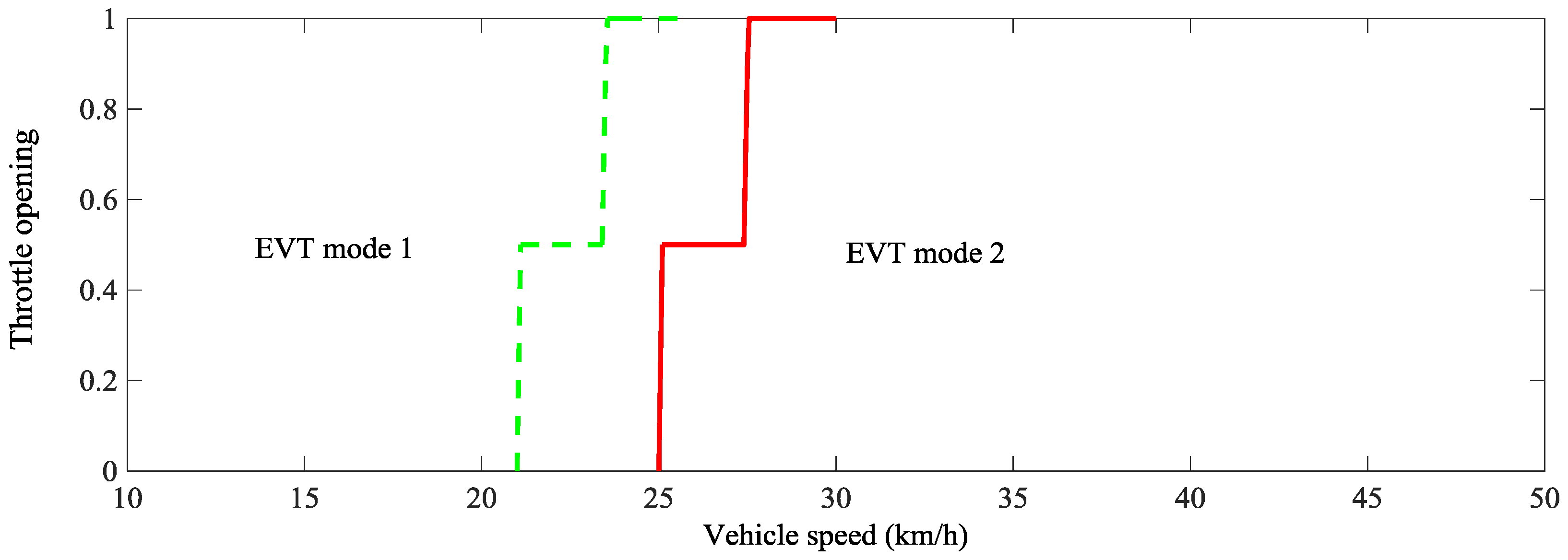
3.2. Shift Schedule Design of the Hybrid Heavy-Duty Vehicle

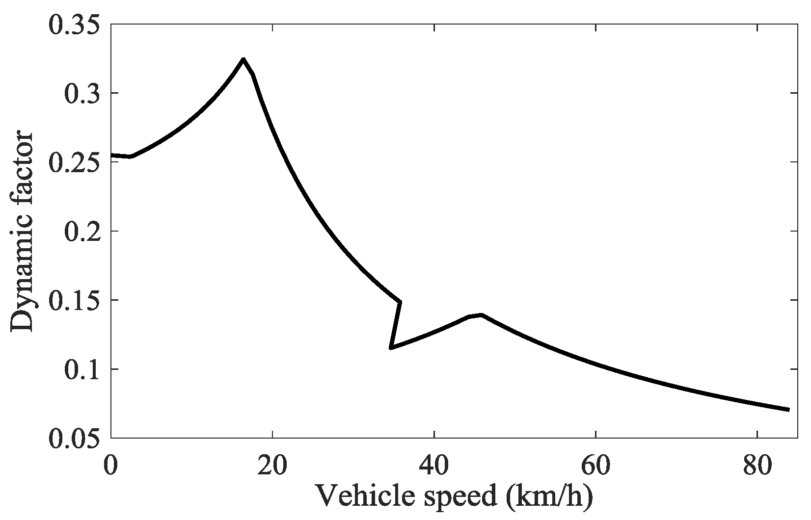
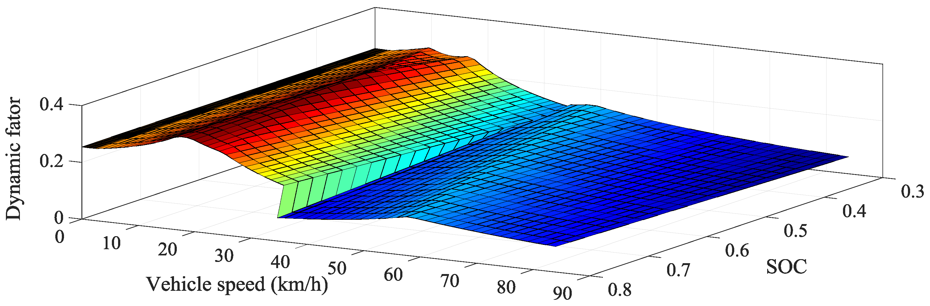
3.2.1. Dynamic Shift Schedule Design

The purpose of the dynamic shift schedule design is to obtain the optimal dynamic performance and acceleration of the hybrid HDV by fully using the vehicle’s traction characteristics. Generally, graphical method is widely used to design the dynamic shift schedule, which determines the optimal shift point and selects the intersection points of adjacent gear acceleration curves under the same throttle opening. Please note that the dynamic factor, as the index of the vehicle’s tractive and speed qualities, is given by the Equation:
D = F t F a i r M
where D is the dynamic factor, F t is the tractive force at the vehicle’s driving wheels, and F a i r is the air resistance to the vehicle’s movement. The dynamic factor, which is usually given as a percentage, characterizes the ability of the vehicle to develop maximum speed, to overcome rolling and grade resistances, and to accelerate. In this paper, the graphical method is applied to design a three-parameter dynamic shift schedule (throttle opening, vehicle speed, and SOC) of the hybrid HDV with PST.
Regardless of the battery power impact on the vehicle’s traction characteristics, the dynamic factor of the hybrid HDV under the full throttle opening ( α = 1 ) can be calculated by Equations (25)–(27), as shown in Figure 7.
To ensure the vehicle working with the MGs the maximum torque in the transient state, it is necessary to find the corresponding external MG’s characteristic curve based on the different output speeds. However, since the MG’s power is restricted by the power balance, whether the battery can provide the required power of the motor or store the generated power of the generator is another important factor to consider. Based on the power balance of the hybrid HDV, the following relationships can be obtained as:
P M G 1 = T M G 1 ω M G 1 9550 , P M G 2 = T M G 2 ω M G 2 9550
P M G 1 + P M G 2 + P b a t = 0
where P M G 1 , P M G 2 are the MG1 power and the MG2 power, respectively. In this paper, the rated power of the battery is 200 kW, and the SOC is set to 0.3–0.8. It is assumed that the battery power is proportionally linear with the SOC—that is, when the SOC is 0.3, the corresponding battery power is −200 kW; when the SOC is 0.55, the corresponding battery power is 0; when the SOC is 0.8, the corresponding battery power is 200 kW. Therefore, the dynamic factor of the hybrid HDV with SOC can be expressed as shown in Figure 8. It is seen that when the SOC lies between 0.3 and 0.355, the dynamic factor of EVT Mode 2 is higher than that of EVT Mode 1, while after the SOC is greater than 0.355, the dynamic factor of EVT Mode 1 is always higher than that of EVT Mode 2. Therefore, the dynamic shift schedule can be designed as: when the SOC is more than 0.355, the shift point chooses the maximum speed of EVT Mode 1; however, when the SOC is less than 0.355, the vehicle enters the EVT Mode 2 in advance, thus making the hybrid HDV optimal dynamic performance. On the other hand, when the throttle opening α lies between 0 and 1, the engine power and the battery power can vary in the same proportion, which results in the same proportion of decline for the dynamic factor. Therefore, the change of the throttle opening has no impact on the selecting of the shift point.
Excessive repetition of gear shifts, which is called as shift hunting, should be avoided for the shift schedule design. In this paper, a 4 km/h speed shift delay is set between the upshift line (EVT Mode 1 shift to EVT Mode 2) and the downshift line (EVT Mode 2 shifts to EVT Mode 1), which is an effective method to avoid the frequent mode shift phenomenon.
According to the above analysis, the dynamic shift schedule of the hybrid HDV can be described as in Figure 9.

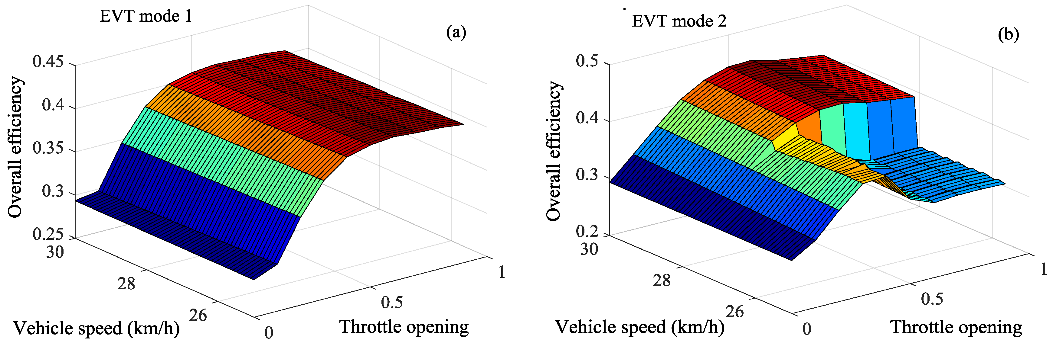
3.2.2. Economic Shift Schedule Design

The purpose of the economic shift schedule design is to achieve the optimal overall efficiency of the hybrid HDV. The transmission efficiency of PST, the efficiency of the MG’s operating region, and the power loss of the engine and the battery are critical factors that significantly influence the overall efficiency of the hybrid HDV [34]. Usually, when the working mode of the MG changes, the operating point of the engine can adjust to achieve better fuel economy. Therefore, proper powertrain system matching can make the vehicle achieve optimal overall efficiency. In this section, the graphical method is also used to design a two-parameter economic shift schedule (throttle opening and vehicle speed) of the hybrid HDV with PST.
Figure 10 shows the power flow for the hybrid HDV, where η e s is the conversion efficiency from the fuel oil to the engine, which is related to the operating point of the engine; η e m = P e f f _ e n g i n e / P e , P e f f _ e n g i n e is the effective power of the engine, which is used to drive the vehicle, and P e is the engine power; since the operating state of the PST and the MGs is relevant, η P S T is the transmission efficiency of the PST and the MGs, P e l e is the two MGs’ electrical power, η b a t is the battery discharging efficiency, P o is the output power from the output shaft. It is noted that when P e l e > 0 , it represents the consumed electrical power of the MGs, and thus the engine and the battery, as the vehicle’s power sources, transfer the power to the wheel based on the dashed line direction; when P e l e < 0 , the generated electrical power of the MGs stores in the battery, and thus the engine provides the only power source to drive the vehicle based on the solid line direction. The detailed description of the overall efficiency calculation for the hybrid HDV with PST can be found in the previous research work [7,34].
Therefore, the overall efficiency of the hybrid HDV can be expressed as:
η z = { P e η em + P e l e P e η es + P e l e η b a t η P S T     P e l e > 0 P o P e l e η b a t P e η es     P e l e < 0
where η z is the overall efficiency of the hybrid HDV. Given that SOC is 0.6, the overall efficiencies of different modes can be obtained with respect to the throttle opening and the vehicle speed, as shown in Figure 11.
The economic shift schedule can be obtained from the intersection line of curved surfaces between the EVT Mode 1 and the EVT Mode 2, as shown in Figure 12. It is seen that when the throttle open is less than 0.5, there is no intersection line of curved surfaces between the EVT Mode 1 and the EVT Mode 2, therefore the minimum speed 25 km/h is selected as the shift point; however, when the throttle open lies between 0.5 and 1, the only intersection line of the curved surfaces is selected as the shift schedule. Similarly, a 4 km/h shift delay is used to avoid frequent shift operation under certain driving conditions.
According to the above analysis, the economic shift schedule of the hybrid HDV can be described as in Figure 13.

4. Mode Shift Control Strategy for the Hybrid Heavy-Duty Vehicle

The section holds the viewpoint that the mode shift performance of the hybrid HDV from EVT Mode 1 to EVT Mode 2 are analyzed under the accelerated condition, and then a control strategy of MG torque compensation is proposed.

4.1. Shift Schedule Design of the Hybrid Heavy-Duty Vehicle

Figure 14 shows the mode shift characteristics simulation model of the hybrid HDV with PST based on MATLAB/Simulink, which represents the powertrain model obtained above. Figure 15 presents the dynamic responses of the hybrid HDV from EVT Mode 1 to EVT Mode 2. Refer to the above shift schedule design, the operational mode can be divided into four stages in sequence: EVT Mode 1 (Mode 1), clutch engaging stage (Mode 2), brake disengaging stage (Mode 4) and EVT Mode 2 (Mode 4) (Figure 15a). When the mode shift signal is input at Mode 2, the vehicle enters the mode shift phase. The pressure signal of the clutch increases and the pressure signal of the brake decrease during mode shift, as determined by the oil pressure of the clutch and brake (Figure 15b).
According to Equations (5) and (7), MG1, as the engine load, has a direct impact on the engine torque, while MG2 torque has no effect on the engine torque, MG2 enters an idle mode and the MG2 torque is approximate 0 (Figure 15c). It is seen that the MG1 speed maintains steady, whereas the MG2 speed rapidly increases during mode shift (Figure 15e,f). This behavior happens because the MG1 speed is calculated by the engine speed and the output speed, both of which hardly change during mode shift. On the other hand, the MG2 speed is calculated by the r3 speed and the output speed. Although the output speed hardly changes, the r3 speed rapidly increases. Furthermore, the decline of the vehicle speed and the output torque interruption occur during mode shift (Figure 15g,h), and this torque shock can result in poor SQ.
Based on Equations (12)–(16), the output torque during mode shift can be derived as follows:
T o = ( 1 + K 3 ) T M G 2 ( 1 + K 1 + K 2 ) ( 1 + K 3 ) K 1 K 2 T M G 1 + ( 1 + K 1 + K 2 ) ( 1 + K 3 ) K 1 K 2 J M G 1 ω ˙ M G 1 ( 1 + K 3 ) J M G 2 ω ˙ M G 2
A comparison of Equations (6) and (31) illustrates that the additional variations in the transition torque during mode shift are generated by the dynamic responses of the MG1 and MG2 inertias. Therefore, these behaviors lead to the interruption in the transition torque. However, Figure 15e shows that the MG1 speed maintains steady during mode shift, which can be assumed that ω ˙ M G 1 =   0 . Consequently, the inertia torque due to the MG2 speed variation ω ˙ M G 2 is the primary reason for the occurrence of the output torque interruption.

4.2. Mode Shift Control Strategy

The above-mentioned simulation results demonstrate that the occurrence of the torque interruption during mode shift is because of the negative impact of the inertia torques of MGs. In this paper, a control strategy to avoid the output torque interruption by regulating the MG2 torque is proposed, as shown in the following.
Figure 15c shows that the MG2 enters idle mode during mode shift and the MG2 torque is about zero. Under the condition of coordinating the engine and MG1, the MG2 torque can be used to compensate the output torque during mode shift. Based on the dynamic equations of the hybrid HDV, the compensation torque of the MG2 during mode shift can be derived, as described in Equation (32):
{ T M G 2 _ c o m p = c K 2 a c ( 1 + K 2 ) T e + c + ( 1 + K 1 ) a c K 1 T M G 1 + ( 1 + K 3 J o b c a d c 1 1 + K 3 ) T f 1 + K 3 J o b c a d c T o a = K 1 K 2 ( 1 + K 1 ) ( 1 + K 2 ) 2 J e 1 K 1 J M G 1 b = ( 1 + K 1 + K 2 ) ( 1 + K 1 ) ( 1 + K 2 ) 2 J e + J M G 2 + 1 ( 1 + K 3 ) 2 J o c = ( 1 + K 1 ) K 1 J M G 1 + K 1 K 2 2 ( 1 + K 1 ) ( 1 + K 2 ) 2 J e d = ( 1 + K 1 + K 2 ) K 2 ( 1 + K 1 ) ( 1 + K 2 ) 2 J e
where a, b, c, d are specific parameters to simplify the expression of the compensation torque of the MG2. Therefore, the inertia torque of the MG2 torque from EVT Mode 1 to EVT Mode 2 is achieved as the sum of the compensation torque of the MG2 in the transition state and the demanded MG2 torque in the steady state according to:
T M G 2 _ d m d = T M G 2 + T M G 2 _ c o m p

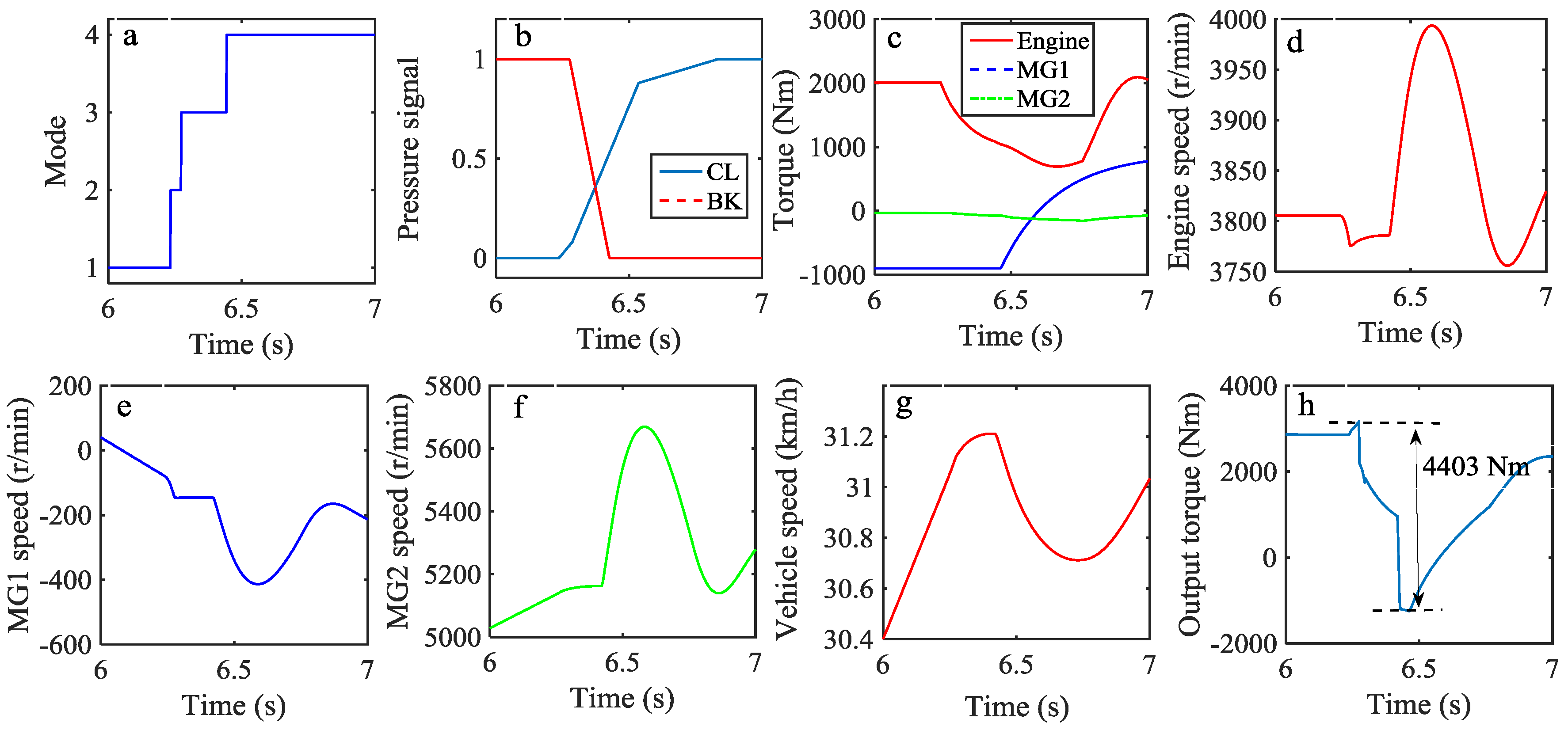
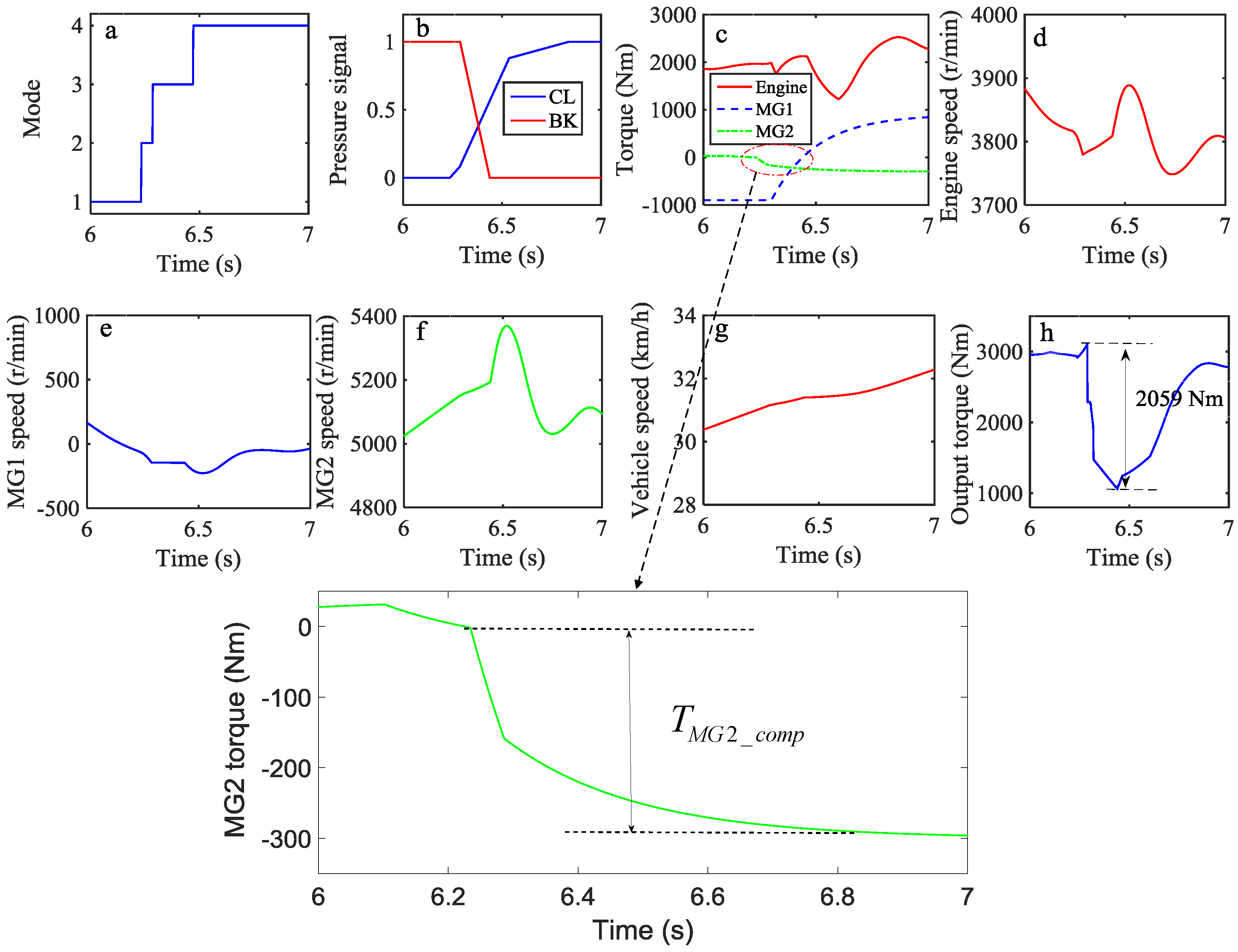
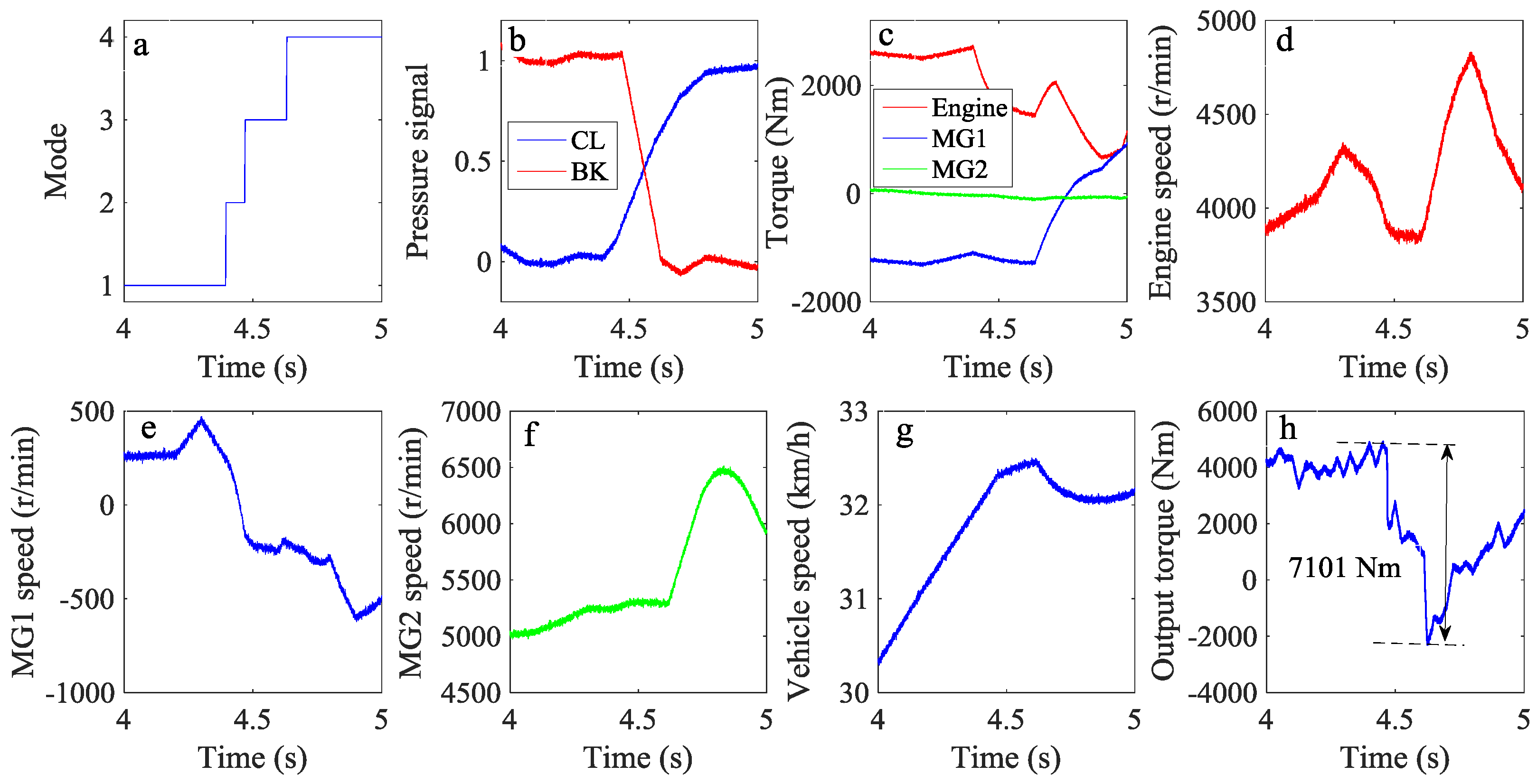
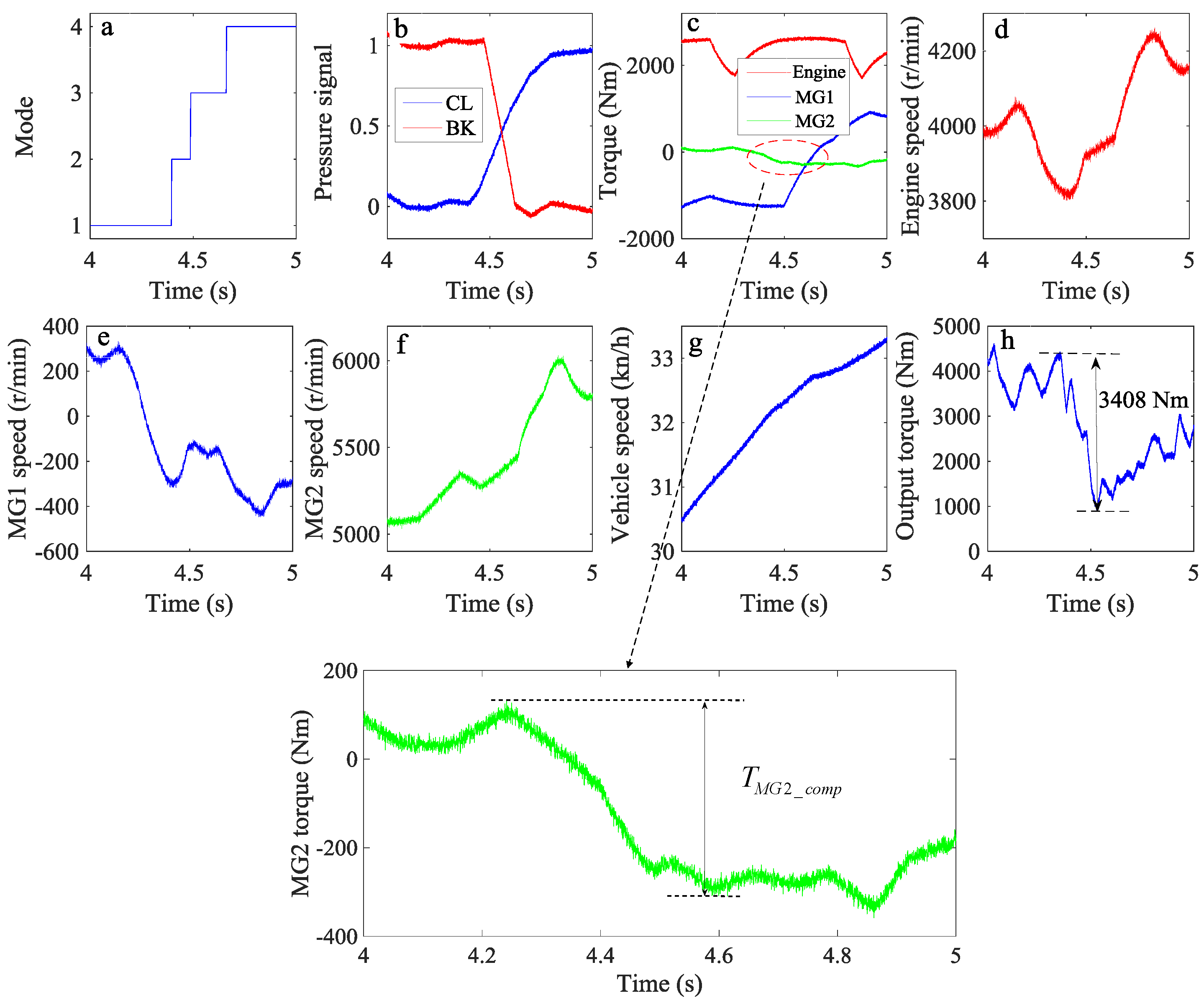
5. Results and Discussion

5.1. Simulation Results and Discussion

To examine the shift characteristics of the proposed control strategy during mode shift, simulation results of the hybrid HDV developed with the use of the proposed control strategy from EVT Mode 1 to EVT Mode 2 are presented, as shown in Figure 16. By comparison with Figure 15, it is found that, without control, the peak-to-peak output torque is 4403 Nm during mode shift and the torque interruption occurs with a large negative profile (Figure 15h); this torque variation can result in poor SQ. Furthermore, the vehicle speed shows a declining behavior (Figure 15g). On the other hand, when the control strategy is applied, the MG2 torque decreases during mode shift (Figure 16c), and the MG2 torque is determined by Equation (33). It is seen that the vehicle speed increases steadily (Figure 16g). More importantly, the output torque variation in the driveshaft is reduced to 2059 Nm, corresponding to a reduction of 53%, and no torque interruption occurs (Figure 16h), which effectively improves the SQ.

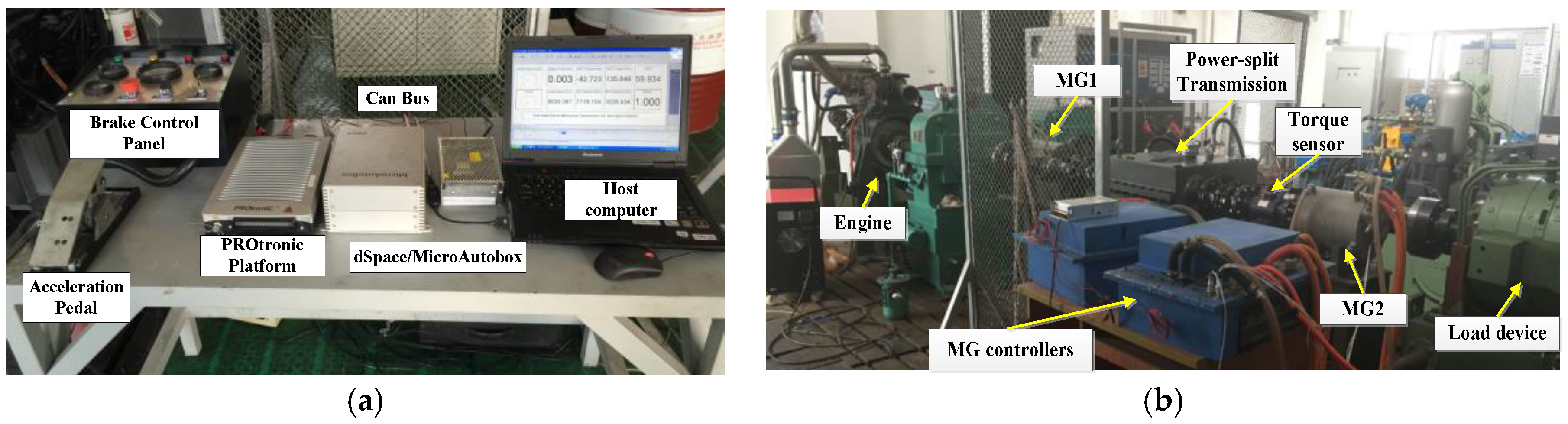
5.2. Experimental Results and Discussion

In this paper, a bench test of the hybrid HDV with PST is constructed and implemented to further validate the shift characteristics of the proposed control strategy. Figure 17a shows the hardware devices that involve using dSPACE (dSPACE/MicroAutoBox, dSPACE GmbH, Paderborn, NRW, German) and the PROtroniC (PROtroniC/USG, AFT Atlas Fahrzeugtechnik GmbH, Werdohl, NRW, German). The hardware devices are used as data acquisition devices that can transmit signals and experimental data between the controllers and the bench test. Figure 17b shows the bench test of the hybrid HDV with PST.
The mode shift test from EVT Mode 1 to EVT Mode 2 has been carried out on the bench tester. It is found that, without a control strategy, the time of shift phase is about 0.27 s (Figure 18a). The vehicle speed shows a declining behavior (Figure 18g), and the output torque variation is 7101 Nm with the occurrence of the torque interruption during mode shift (Figure 18h). When the proposed MG torque control is applied, MG2 torque decreases during mode shift (Figure 19c). The vehicle speed increases steadily (Figure 19g), the control strategy enables the output torque variation to reduce by 52% to 3408 Nm, no large negative torque is produced, and torque interruption has also been eliminated (Figure 19h).

6. Conclusions

To optimize the dynamic performance and economic performance of the vehicle, a shift schedule design for a hybrid HDV with PST has been provided in this paper using a graphical development method, including three-parameter dynamic shift schedule design (throttle opening, vehicle speed, and SOC) and two-parameter economic shift schedule design (throttle opening and vehicle speed). To evaluate the shift performance and the designed shift schedule, a mode shift characteristics simulation model is developed. Based on the dynamic equations of the hybrid HDV, it is seen that the output torque interruption occurs due to the inertia torques of MGs, which result in unwanted transient torque and deteriorate the vehicle’s SQ. To solve the problem of the inappropriate mode shift, a torque control strategy is proposed that considers the MG2 torque compensation to reduce the torque interruption in the output shaft. The magnitude of the compensation torque can be derived as a real-time feature through the dynamic equations from EVT Mode 1 to EVT Mode 2.
To examine the shift characteristics of the proposed control strategy, simulations are performed. In addition, a bench test of the hybrid HDV is implemented to further validate the proposed control strategy. The simulation and experimental results indicate that the peak-to-peak output torque in the output shaft can be effectively reduced and no torque interruption occurs by the proposed control strategy, thereby significantly improving the vehicle’s SQ.

Acknowledgments

The authors are grateful for the financial support from the National Natural Science Foundation of China (Grant Nos. 51205020, 51575043 and U1564210).

Author Contributions

Kun Huang validated the dynamic model, designed the shift schedule, implemented the proposed strategy, and wrote the paper; Changle Xiang and Yue Ma provided theoretical guidance; Weida Wang provided important help with the experimental setup; Reza Langari gave many insights during the final write-up.

Conflicts of Interest

The authors declare no conflict of interest.

References

  1. Syed, F.U.; Kuang, M.L.; Czubay, J.; Ying, H. Derivation and experimental validation of a power-split hybrid electric vehicle model. IEEE Trans. Veh. Technol. 2006, 55, 1731–1747. [Google Scholar] [CrossRef]
  2. Li, L.; Yan, B.; Song, J.; Zhang, Y.; Jiang, G. Two-step optimal energy management strategy for single-shaft series-parallel powertrain. Mechatronics 2016, 36, 147–158. [Google Scholar] [CrossRef]
  3. Mashadi, B.; Emadi, S.A. Dual-mode power-split transmission for hybrid electric vehicles. IEEE Trans. Veh. Technol. 2010, 59, 3223–3232. [Google Scholar] [CrossRef]
  4. Xiang, C.; Huang, K.; Ma, Y.; Liu, H.; Jia, S. Analysis of characteristics for mode switch of dual-mode electro-mechanical transmission (EMT). In Proceedings of the 2014 IEEE 80th Vehicular Technology Conference (VTC2014-Fall), Vancouver, BC, Canada, 14–17 September 2014.
  5. Zhuang, W.; Zhang, X.; Ding, Y.; Wang, L.; Hu, X. Comparison of multi-mode hybrid powertrains with multiple planetary gears. Appl. Energy 2016, 178, 624–632. [Google Scholar] [CrossRef]
  6. Xiang, C.; Huang, K.; Ma, Y.; Zhao, Y. Stability analysis for mode switch of multi-mode electro-mechanical transmission (EMT). In Proceedings of the IEEE Transportation Electrification Conference & Expo Asia-Pacific, Beijing, China, 31 August–3 September 2014.
  7. Wang, W.; Xiang, C.; Liu, H.; Jia, S. A model-predictive-control-based power management strategy for a power-split electromechanical transmission. Proc. Inst. Mech. Eng. Part D J. Automob. Eng. 2016, 230, 1987–2001. [Google Scholar] [CrossRef]
  8. Chen, Z.; Mi, C.C.; Xu, J.; Gong, X.; You, C. Energy management for a power-split plug-in hybrid electric vehicle based on dynamic programming and neural networks. IEEE Trans. Veh. Technol. 2014, 63, 1567–1580. [Google Scholar] [CrossRef]
  9. Ouyang, M.; Zhang, W.; Wang, E.; Yang, F.; Li, J.; Li, Z.; Ye, X. Performance analysis of a novel coaxial power-split hybrid powertrain using a CNG engine and supercapacitors. Appl. Energy 2015, 157, 595–606. [Google Scholar] [CrossRef]
  10. Zhuang, W.; Zhang, X.; Zhao, D.; Peng, H.; Wang, L. Optimal design of three-planetary-gear power-split hybrid powertrains. Int. J. Automot. Technol. 2016, 17, 299–309. [Google Scholar] [CrossRef]
  11. Montazeri-Gh, M.; Mahmoodi-k, M. Development a new power management strategy for power split hybrid electric vehicles. Transp. Res. D Transp. Environ. 2015, 37, 79–96. [Google Scholar] [CrossRef]
  12. Wang, Y.; Sun, Z. Dynamic analysis and multivariable transient control of the power-split hybrid powertrain. IEEE/ASME Trans. Mechatron. 2015, 20, 3085–3097. [Google Scholar] [CrossRef]
  13. Chen, Z.; Mi, C.C.; Xiong, R.; Xu, J.; You, C. Energy management of a power-split plug-in hybrid electric vehicle based on genetic algorithm and quadratic programming. J. Power Sources 2014, 248, 416–426. [Google Scholar] [CrossRef]
  14. Xiang, C.; Ding, F.; Wang, W.; He, W. Energy management of a dual-mode power-split hybrid electric vehicle based on velocity prediction and nonlinear model predictive control. Appl. Energy 2017, 189, 640–653. [Google Scholar] [CrossRef]
  15. Shen, W.; Yu, H.; Hu, Y.; Xi, J. Optimization of Shift Schedule for Hybrid Electric Vehicle with Automated Manual Transmission. Energies 2016, 9, 220. [Google Scholar] [CrossRef] [Green Version]
  16. Pettersson, M.; Nielsen, L. Gear shifting by engine control. IEEE Trans. Control. Syst. Technol. 2000, 8, 495–507. [Google Scholar] [CrossRef]
  17. Ying, H.; Xianlei, S.; Shili, X.; Fujun, Z.; Yunshan, G. Design of gear shifting rules on the basis of power performance and fuel economy and experimental study on them. Automob. Technol. 2004, 11, 007. [Google Scholar]
  18. Yang, C.; Song, J.; Li, L.; Li, S.; Cao, D. Economical launching and accelerating control strategy for a single-shaft parallel hybrid electric bus. Mech. Syst. Signal Process. 2016, 76, 649–664. [Google Scholar] [CrossRef]
  19. Yang, C.; Jiao, X.; Li, L.; Zhang, Y.; Zhang, L.; Song, J. Robust coordinated control for hybrid electric bus with single-shaft parallel hybrid powertrain. IET Control Theory Appl. 2015, 9, 270–282. [Google Scholar] [CrossRef]
  20. Pisu, P.; Rizzoni, G. A comparative study of supervisory control strategies for hybrid electric vehicles. IEEE Trans. Control Syst. Technol. 2007, 15, 506–518. [Google Scholar] [CrossRef]
  21. Ngo, V.; Hofman, T.; Steinbuch, M.; Serrarens, A. Predictive gear shift control for a parallel hybrid electric vehicle. In Proceedings of the 2011 IEEE Vehicle Power and Propulsion Conference, Chicago, IL, USA, 6–9 September 2011.
  22. Zhao, Z.G.; Chen, H.J.; Zhen, Z.X.; Yang, Y.Y. Optimal torque coordinating control of the launching with twin clutches simultaneously involved for dry dual-clutch transmission. Veh. Syst. Dyn. 2014, 52, 776–801. [Google Scholar] [CrossRef]
  23. Beck, R.; Richert, F.; Bollig, A.; Abel, D.; Saenger, S.; Neil, K.; Noreikat, K.E. Model predictive control of a parallel hybrid vehicle drivetrain. In Proceedings of the 44th IEEE Conference on Decision and Control, Seville, Spain, 12–15 December 2005; pp. 2670–2675.
  24. Kim, S.; Park, J.; Hong, J.; Lee, M.; Sim, H. Transient Control Strategy of Hybrid Electric Vehicle during Mode Change; SAE Technical Paper; SAE International: Warrendale, PA, USA, 2009. [Google Scholar]
  25. Zhang, H.; Zhang, Y.; Yin, C. Hardware-in-the-loop simulation of robust mode transition control for a series–Parallel hybrid electric vehicle. IEEE Trans. Veh. Technol. 2016, 65, 1059–1069. [Google Scholar] [CrossRef]
  26. Shi, G.; Dong, P.; Sun, H.Q.; Liu, Y.; Cheng, Y.J.; Xu, X.Y. Adaptive control of the shifting process in automatic transmissions. Int. J Automot. Technol. 2017, 18, 179–194. [Google Scholar] [CrossRef]
  27. Chen, L.; Xi, G.; Sun, J. Torque coordination control during mode transition for a series—Parallel hybrid electric vehicle. IEEE Trans. Veh. Technol. 2012, 61, 2936–2949. [Google Scholar] [CrossRef]
  28. Wang, C.; Zhao, Z.; Zhang, T.; Li, M. Mode transition coordinated control for a compound power-split hybrid car. Mech. Syst. Signal Process. 2017, 87, 192–205. [Google Scholar] [CrossRef]
  29. Zeng, X.; Yang, N.; Wang, J.; Song, D.; Zhang, N.; Shang, M.; Liu, J. Predictive-model-based dynamic coordination control strategy for power-split hybrid electric bus. Mech. Syst. Signal Process. 2015, 60, 785–798. [Google Scholar] [CrossRef]
  30. Choi, W.; Kang, J.; Hong, S.; Kim, H. Development of a control algorithm to reduce torque variation for the dual mode HEV during mode shift. In Proceedings of the 2011 IEEE Vehicle Power and Propulsion Conference, Chicago, IL, USA, 6–9 September 2011.
  31. Yan, F.; Wang, J.; Huang, K. Hybrid electric vehicle model predictive control torque-split strategy incorporating engine transient characteristics. IEEE Trans. Veh. Technol. 2012, 61, 2458–2467. [Google Scholar] [CrossRef]
  32. Xiang, C.; Wang, Y.; Hu, S.; Wang, W. A new topology and control strategy for a hybrid Battery-Ultracapacitor energy storage system. Energies 2014, 7, 2874–2896. [Google Scholar] [CrossRef]
  33. Zeng, X.; Wang, J. A parallel hybrid electric vehicle energy management strategy using stochastic model predictive control with road grade preview. IEEE Trans. Control Syst. Technol. 2015, 23, 2416–2423. [Google Scholar] [CrossRef]
  34. Han, L.J.; Xiang, C.; Yan, W.J.; Qi, Y.L.; Liu, R. Study on system efficiency and power flow optimization for dual-mode hybrid electric vehicle. In Proceedings of the FISITA 2012 World Automotive Congress, Beijing, China, 27 November 2012; pp. 401–415.
Figure 1. Configuration of power-split hybrid electric vehicle (HEV). MG: motor-generator.
Energies 10 00177 g001
Figure 2. Configuration of hybrid heavy-duty vehicle (HDV) with power-split transmission (PST).
Energies 10 00177 g002
Figure 3. Structure of planetary gear (PG): (a) PG; and (b) its level diagram analogy.
Energies 10 00177 g003
Figure 4. Lever diagram of the hybrid HDV with PST for each mode: (a) EVT Mode 1; and (b) EVT Mode 2.
Energies 10 00177 g004
Figure 5. Map of the battery pack’s characteristics.
Energies 10 00177 g005
Figure 6. Analysis of theoretical shift point.
Energies 10 00177 g006
Figure 7. Dynamic factor of the hybrid HDV without SOC.
Energies 10 00177 g007
Figure 8. Dynamic factor of the hybrid HDV with SOC.
Energies 10 00177 g008
Figure 9. Dynamic shift schedule of the hybrid HDV with PST.
Energies 10 00177 g009
Figure 10. Power flow for the hybrid HDV.
Energies 10 00177 g010
Figure 11. Overall efficiency for the hybrid HDV for each mode: (a) overall efficiency for EVT Mode 1; and (b) overall efficiency for EVT Mode 2.
Energies 10 00177 g011
Figure 12. Intersection line of curved surfaces between EVT Mode 1 and EVT Mode 2: (a) intersection line based on three-dimensional view; and (b) intersection line based on two-dimensional view.
Energies 10 00177 g012
Figure 13. Economic shift schedule of the hybrid HDV with PST.
Energies 10 00177 g013
Figure 14. Block diagram of the hybrid HDV in MATLAB/Simulink.
Energies 10 00177 g014
Figure 15. Mode shift characteristics of the hybrid HDV: (a) mode; (b) pressure signal; (c) torques of engine and MGs; (d) engine speed; (e) MG1 speed; (f) MG2 speed; (g) vehicle speed; and (h) output torque.
Energies 10 00177 g015
Figure 16. Mode shift characteristics of the hybrid HDV with MG2 torque control: (a) mode; (b) pressure signal; (c) torques of engine and MGs; (d) engine speed; (e) MG1 speed; (f) MG2 speed; (g) vehicle speed; and (h) output torque.
Energies 10 00177 g016
Figure 17. Bench test for the hybrid HDV with PST: (a) data acquisition devices; and (b) bench test configuration.
Energies 10 00177 g017
Figure 18. Experimental results of the hybrid HDV without control. (a) Mode; (b) Pressure signal; (c) Torques of Engine and MGs; (d) Engine speed; (e) MG1 speed; (f) MG2 speed; (g) Vehicle speed; and (h) Output torque.
Energies 10 00177 g018
Figure 19. Experimental results of the hybrid HDV with control: (a) Mode; (b) Pressure signal; (c) Torques of Engine and MGs; (d) Engine speed; (e) MG1 speed; (f) MG2 speed; (g) Vehicle speed; and (h) Output torque.
Energies 10 00177 g019
Table 1. Operation modes of the hybrid HDV with PST: CL: clutch; BK: brake.
ModeMG1MG2CLBK
EVT Mode 1GeneratorMotorDisengagedEngaged
EVT Mode 2MotorGeneratorEngagedDisengaged
Table 2. Main parameters of the hybrid HDV with PST.
ComponentsParameterValue
EngineMaximum speed4250 r/min
Maximum torque2754 Nm
Motor-generatorMaximum speed6050 r/min
Maximum torque1342 Nm
BatteryCapacity70 Ah
Bus voltage900 V
PGsK12.13
K22.13
K32.33
VehicleMass45,000 kg
Front gear ratio1.4
Final gear ratio4.1
Clutch brakeKinetic friction coefficient0.06
Static friction coefficient0.1
Pressure0–2.5 MPa

