Article

Efficiency Analysis of the Main Components of a Vertical Closed-Loop System in a Borehole Heat Exchanger

by
Cristina Sáez Blázquez
*,
Arturo Farfán Martín
,
Ignacio Martín Nieto
,
Pedro Carrasco García
,
Luis Santiago Sánchez Pérez
and
Diego González-Aguilera
Department of Cartographic and Land Engineering, University of Salamanca, Higher Polytechnic School of Avila, Hornos Caleros 50, 05003 Avila, Spain
*
Author to whom correspondence should be addressed.
Energies 2017, 10(2), 201; https://doi.org/10.3390/en10020201
Submission received: 22 November 2016 / Revised: 30 January 2017 / Accepted: 3 February 2017 / Published: 10 February 2017
(This article belongs to the Special Issue Low Enthalpy Geothermal Energy)

Abstract

:
In vertical closed-loop systems, it is common to use single or double U-tube heat exchangers separated by longitudinal spacers. In addition, the helical-shaped pipe is another configuration that requires lower drilling lengths but it is less used. The aim of the present research is to study the influence of these components on the total efficiency of a borehole heat exchanger (BHE). Thus, the differences between using single/double U-tubes (with or without spacers) and helical pipes are analysed in terms of efficiency. Through different laboratory tests, a small vertical closed-loop system was simulated in order to analyse all these possible configurations. The grouting materials and the temperatures of the ground were modified at the same time in these tests. Regarding the heat exchange process between the ground and the heat carrier fluid, it must be highlighted that the best results were obtained for the helical-shaped pipe configuration. Some of the improvements offered by this heat exchanger typology with respect to the vertical configuration is that a lower drilling depth is required even it requires a larger diameter. This leads to significant economic savings in the performing drilling process. Finally, it is also worth noting the importance of using spacers in vertical U-tubes and that no improvements have been found regarding the use of single or double configuration of U-tubes. Thanks to the laboratory results derived from this study it is possible to establish the optimum behaviour pattern for the entire vertical closed-loop systems.

1. Introduction

Renewable energies are getting more and more important to address the increasing demand of energy. With respect to the geothermal energy, the number of installations has increased over the past decade and continues growing [1]. A conventional closed-loop system of very low temperature is commonly used to heat/cool a certain space or to produce Domestic Hot Water (DHW) [2]. Focusing on the geothermal systems that use closed-loop heat exchangers [3] and in particular on those vertical borehole heat exchangers; they are usually constituted by vertical pipes, generally made of polyethylene PE 100 PN16. A heat carrier fluid (usually a mixture of water and glycol) flows inside these pipes behaving as thermal transmitter between the ground and the rest of components of the installation [4,5,6]. The length of these drillings typically varies from 60 to 300 m (when using vertical pipes), according to the energetic needs to cover in each certain case. For these vertical installations, the most common configurations in relation to the drilling diameter and the design of heat exchangers are presented in Table 1 [7].
Another less known design is the helical heat exchanger. This type of pipe with diameters of around 400 mm requires much smaller drilling lengths and they are equally made of high quality polyethylene. These helical pipes can be installed in boreholes of only 3–5 m although drilling lengths can vary and be higher depending on the installation in question [8,9,10].
In both types of configurations (vertical or helical), the space between the hole wall and the heat exchangers is filled by a thermal conductive material to ensure the thermal exchange between ground and fluid inside the pipe. This material, known as geothermal grout, must have a series of mechanical and thermal characteristics [11,12].
Particular attention is needed for the following factors:
  • Compactness, to guarantee the borehole stability and its easy injection to the hole.
  • Sealing ability, providing a hydraulic barrier that avoids the pollution of aquifers.
  • Low hydraulic conductivity.
  • High thermal conductivity for an efficient heat transfer between the pipe and the ground. As a rule, it is recommended that the grouting material has a higher thermal conductivity value than the thermal conductivity of the ground to guarantee an efficient working of the borehole heat exchanger. In any cases, both thermal conductivities should be the highest possible. Some relations between the ground and the grout should be implemented. When the thermal conductivity of the ground is <2 W/mK, the thermal conductivity of the grout should be ≥ than the thermal conductivity of the ground and when the thermal conductivity of the ground is ≥2 W/mK, the thermal conductivity of the grout should be ≥2 W/mK [13].
The main objective of this research is to study the efficiency of different designs depending on the heat exchangers and the grouting material used. Through the representation in laboratory of a series of configurations commonly used and other more innovative systems, it was possible to select the design that provides the most favourable results in the thermal exchange with the ground constituting at the same time the best solution to achieve the greatest possible effectiveness for this kind of installations. A good decision in the design of the geothermal heat exchangers and the grouting material could mean important economic savings since the total drilling length could be reduced [14].
Several studies have been found about the comparison of the different heat exchangers considered in this manuscript and the main decisive parameters in a borehole heat exchanger. Zarrella et al. [15] concluded that the thermal performance of the helical-shaped pipe was better than the double U-tube heat exchanger. When the helical heat exchanger was 33% shorter than the double U-tube, each heat exchanger provided the same thermal performance; it denotes that this non-conventional type of heat exchanger could be used to reduce installation costs. Han and Yu [16] emphasized the importance of optimizing the thermal conductivity and specific heat capacity of backfill materials. Congedo et al. [17] resolved that the most important parameter for the heat transfer performance of the system is the thermal conductivity of the ground around the heat exchanger. They also stablished that the optimal ground type is that with the highest thermal conductivity.
However, most of these studies only offer a theoretical simulation not based on the practical experience as this study does [18,19,20]. On top of that, this study combines different heat exchangers with different grouting materials and different ground temperatures which allow making a complete comparison and description of a borehole heat exchanger.

2. Materials and Methods

The experimental methodology consisted of the representation in laboratory of a vertical borehole heat exchanger with a drilling length of only one meter. From this installation, a set of configurations were tested for selecting the one that, contributes to increase the total efficiency of the geothermal system. The comparison among the different cases of study has been made based on the difference of temperatures of the heat carrier fluid in the entry and exit of the borehole. When this difference is high, the efficiency of the thermal exchange between the ground and fluid is also considerably high. The heat extraction from the ground by the heat carrier fluid is determined by the grouting material (responsible for the heat transmission) and the heat exchanger. Thus, the higher the difference of temperature between the hot and the cold tube of the heat exchanger, the greater the amount of heat collected by the circulating fluid. This fact constitutes an indicator of the heat exchanger and grouting material quality [21,22].
Components used to create the borehole heat exchanger and the configurations tested in the laboratory are presented in Section 2.1.

2.1. Components Used in the Laboratory Tests
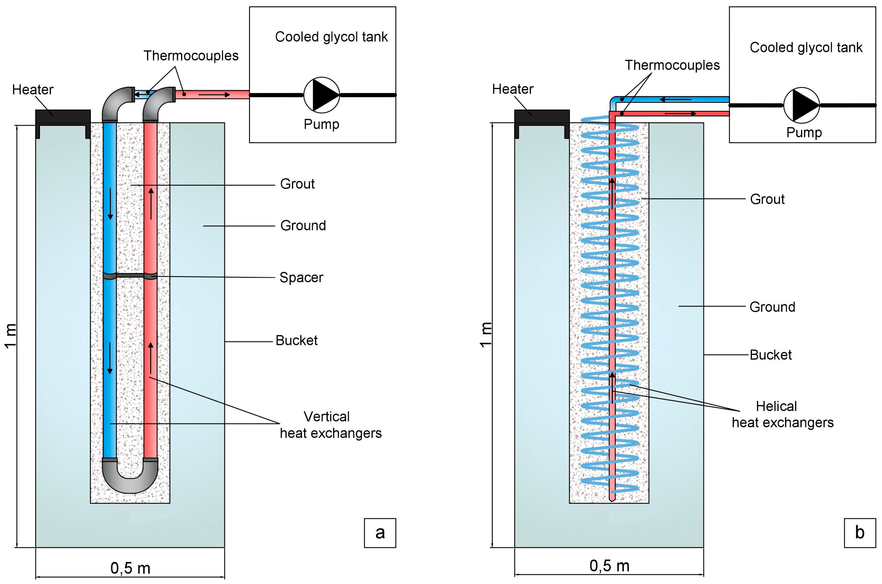
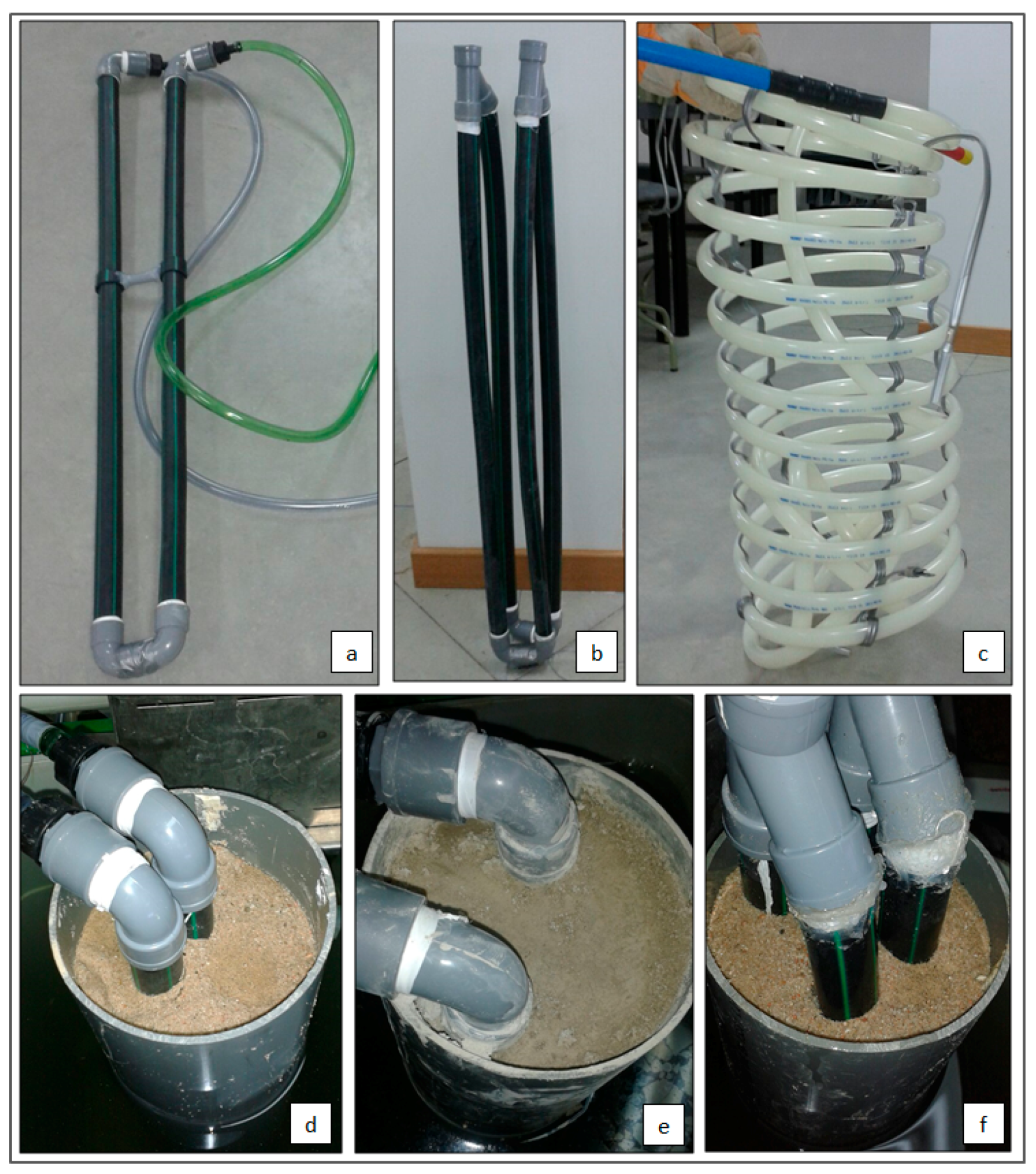
A vertical borehole heat exchanger was reproduced in the laboratory to use it as a basis for the analysis of the effectiveness of this kind of systems according to the heat exchangers, the grouting materials and the temperatures of the ground. The components of this prototype of installation were the following:
  • Heat exchangers
    Heat exchangers considered in the present research were the commonly used single or double U-tube heat exchangers and the helical-shaped pipe, both made of polyethylene and diameter of 32 mm.
  • Spacers
    In some tests, spacers were placed in single and double U-tube heat exchangers to avoid the contact between cold and hot pipes. These elements were of polyethylene.
  • Boost pump
    A boost pump, of 3 W of power, allowed the circulation of the heat carrier fluid through the heat exchangers. The constant volume of flow supplied by this pump was of 6.91 L/h.
  • Bucket
    The system includes a bucket containing water that simulates the ground at a certain temperature. This bucket has a diameter of 0.45 m and a length of 1 m and is made of polyethylene. The rest of components of the geothermal drilling: pipes, heat carrier fluid and grouting material are housed inside this bucket.
  • Resistant heater
    Water contained in the bucket simulating the surrounding ground (considering the ground temperature as constant during the heat extraction) was set at a temperature thanks to the use of a resistant heater that keeps the whole water at a constant temperature.
  • Heat carrier fluid
    The function of the heat carrier fluid is to absorb the heat from the ground by its circulation through the geothermal heat exchangers. The heat carrier fluid used in the present study was a mixture of water-propylene glycol to 30%. It was chosen for being one of the least toxic antifreeze. It does not present any risks for the environment and it can be handled without special security measures.
  • Grouting material
    Several materials are usually used as grout in borehole heat exchangers such as bentonite, sand, cement and detritus coming from the drilling. These materials allow the heat exchange between ground and pipes and must comply with a series of factors explained in Section 1 [23,24,25,26,27]. After testing a series of mixtures, the materials selected as grout were the sand in saturated conditions, in boreholes with presence of water and a mixture constituted by aluminium cement-sand, for the case of boreholes without water. Both mixtures have the suitable thermal and mechanical characteristics to be used as grouting material, with significant values of thermal conductivity, 2.83 W/mK in the case of saturated sand and 2.45 W/mK in the mixture of aluminium cement-sand. Table 2 shows the main characteristics of both materials selected as grouts in the present work.
  • Water
    Water contained in the bucket simulates the surrounding ground. The temperature of this fluid was controlled to study the heat exchange with the rest of components of the installation. Heating this water was possible thanks to a resistant heater which allows setting the temperature at a known value. Additionally, temperature of the water was controlled by an external thermometer to verify the correct working of the resistant heater.
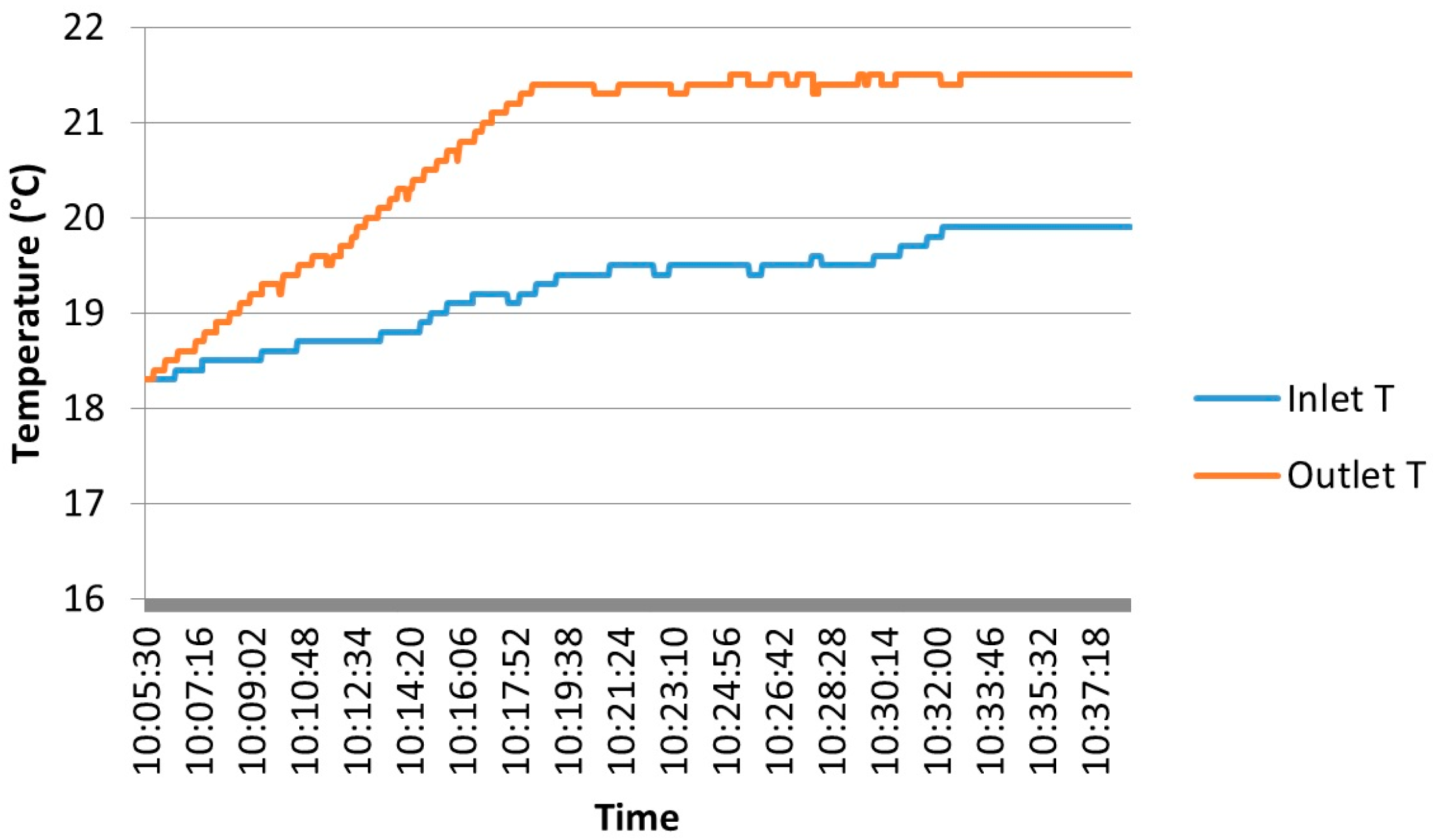
  • Thermocouples
    Inlet and outlet temperatures of the heat carrier fluid were controlled at the end of the heat exchangers by thermocouples connected to a measuring device. These values were essential in the research to compare the different configurations.
    Thermocouples (with an accuracy of ±0.1 °C) were constituted by chrome and aluminium alloys and were connected to a digital thermometer to measure simultaneal temperature in different horizons or areas. Before its use, these sounding lines were duly calibrated according to the International Law ASTM E220 (Test Method for Calibration of Thermocouples by Comparison Techniques) [28].
  • Heat carrier fluid cooling
    Once the heat carrier fluid (mixture of water-propylene glycol) has absorbed the heat from the ground through the drilling, it gets in a cooling tank where its temperature gradually drops back to start a new cycle of heat exchange with the ground.
Figure 1 shows the schema of the borehole heat exchanger represented in laboratory with the single U-tube heat exchanger (Figure 1a) and the helical-shaped pipe (Figure 1b).
The bucket contains water that simulates the ground close to the geothermal drilling. This fluid is set at a specific temperature by a heater placed in the upper area of the bucket that recirculates the whole fluid facilitating a constant temperature at any part of it. A series of thermometers placed in different areas of this bucket allowed to verify that the temperature of the water was in effect constant.
Heat exchangers (vertical or helical) were also inside this bucket and the space between these pipes and the ground (water) was filled by the grouting material.
Finally, a pump placed in the cooled tank of propylene-glycol circulates the heat carrier fluid inside the pipes allowing the absorption of heat on its way through the ground. Thermocouples were placed in the upper part of the pipes to control inlet and outlet temperatures.

2.2. Tested Configurations

Based on the above installation, different configurations were tested modifying three fundamental parameters: heat exchangers, grouting material and ground temperature (water).

2.2.1. Heat Exchangers

Pipes used were the single or double U-tube heat exchangers and the helical-shaped pipe. Different configurations were used in the laboratory tests:
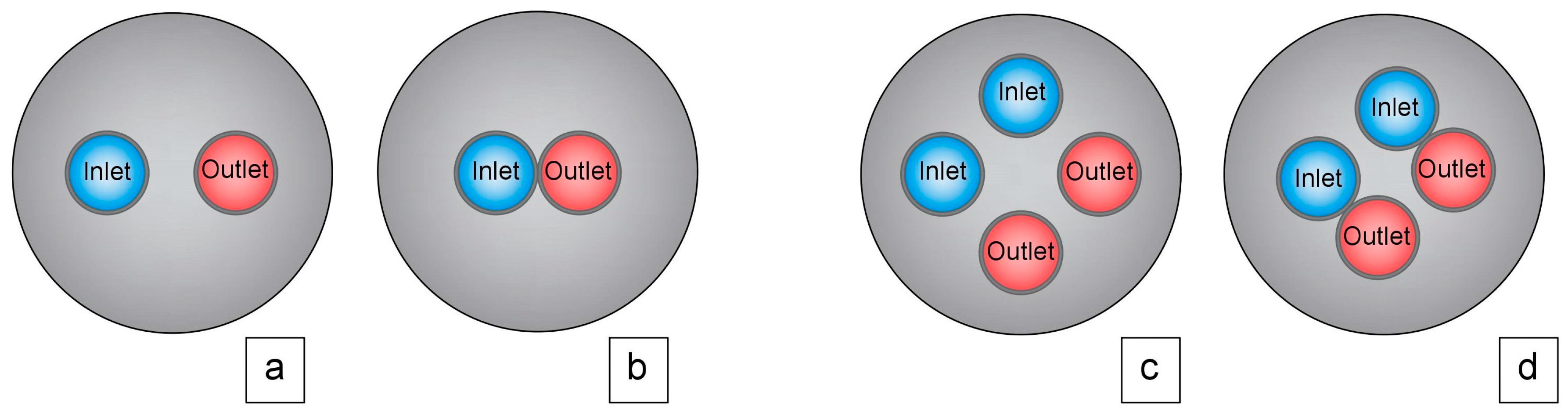
  • Single U-tube with spacers: single vertical pipe with spacer placed in the middle of both tubes to avoid any contact between cold and hot pipes.
  • Single U-tube without spacers: single vertical pipe without spacers and thus, both tubes (cold and hot) are in contact.
  • Double U-tube with spacers: double vertical pipes with spacers to avoid any contact between the four pipes (two cold and two hot).
  • Double U-tube without spacers: double vertical pipes without spacers, that is to say, cold and hot tubes are in contact.
  • Helical-shaped pipe: helical pipe with a central tube where the heat carrier fluid rises up once has taken the heat from the ground.
Figure 2 shows the influence of the use of spacers relative to the position of the single and double U-tubes heat exchangers.

2.2.2. Grouting Material

As previously cited in Section 2.1, two types of grouts were selected to carry out the present research. These grouts comply with a series of general characteristics making them suitable for this use. Additionally, they have a high thermal conductivity value, that is, they have an excellent capacity to conduce the heat. After preparing mixtures constituted by materials commonly used as grouts, some particular thermal and mechanical tests were carried out [29]. One of these tests, that stands out because of its importance is the measuring “in situ” of the thermal conductivity parameter [30,31]. This property was determined by the thermal properties analyser commercially known as KD2 Pro developed by Decagon Devices [32].
KD2 Pro equipment is constituted by a portable controller and a certain sensor (RK-1) that make possible the measuring of two thermal properties: the thermal resistivity and the thermal conductivity. Its operation is based on the infinite line heat source theory and calculates the thermal conductivity by monitoring the dissipation of heat from the needle probe. Heat is applied to the needle for a set heating time, th and temperature is measured in the monitoring needle during heating and for an additional time equal to th after heating. The temperature during heating is computed from Equation (1).
T = m 0 + m 2 t + m 3 l n t
where, m0 is the ambient temperature during heating; m2 is the rate of background temperature drift; m3 is the slope of a line relating temperature rise to logarithm of temperature.
Equation (2) represents the model during cooling.
T = m 1 + m 2 t + m 3 l n t t t h
The thermal conductivity is computed from Equation (3).
k = q 4 m 3
The RK-1 probe (3.9 mm in diameter and 6 cm in length), used in the present work, is capable of measuring the thermal conductivity between the range of 0.1 and 6 W/mK and ±10% of accuracy.
The use of this equipment in samples previously prepared (cylinder blocks of 5 cm of diameter and length superior to the sensor RK-1 length) led to select for the present work the following grouts:
  • Saturated sand: for those cases of boreholes where water is present, an appropriate solution is to use sand as geothermal grout. When this element is saturated of water (in this case from the borehole) has excellent thermal transmission capacities. It has a thermal conductivity value of 2.83 W/mK.
  • Mixture of aluminium cement-sand: this mixture consisting of sand and aluminium cement in proportion 2:1 is suitable for both boreholes with water and without it. Aluminium cement comprised of calcium sulpho-aluminate provides the mixture with a higher thermal conductivity value in comparison with the conventional cement. In addition, the mechanical properties of the mixture make it appropriate to be used as geothermal grout. It has a thermal conductivity value of 2.45 W/mK.

2.2.3. Temperatures

Temperatures of the water that simulates the ground were set in several values to cover a range of possibilities. It allows analysing the behaviour of the installation with different values of this parameter. Thus, temperature values were set in 30, 40 and 50 °C. Temperature of the ground is often under these values (although it depends on the borehole depth), especially in these installations of very low enthalpy geothermal energy. However, and given that it is a small installation with a length of only one meter, temperature increases between hot and cold sources are required to appreciate significant differences among the different assumptions considered.
Cold source was kept constant to the temperature of 6 °C. Due to the presence of this source, the heat carrier fluid coming from the drilling, transfers the heat taken from the ground. Once this fluid has transferred the heat to the cold source, it cools down to start a new cycle.
Table 3 shows each of the configurations tested in laboratory according to the parameters previously described. It should be noted that in the case of helical-shaped pipe, the original design of this pipe was used. In this design there is not contact among the different sections of the pipes, therefore, spacers were not used.
Figure 3 shows several images illustrating the testing process in laboratory. Figure 3a–c represent the three types of heat exchangers used in the present research and the rest of Figure 3d–f show different views of the installation reproduced in laboratory.

3. Results and Discussion

During the test of each of the configurations presented in Table 3, temperatures of the heat carrier fluid were continuously controlled by thermocouples placed at the top of the pipes (in both cold and hot tubes). Once these temperatures were stable (time for stabilization was also measured), they were registered. In this way, the increments of temperatures reached by this fluid (when temperatures were stable) constitute an indication of efficiency of the system tested in each particular case. This fact allows for stablishing a comparison among the set of systems represented in laboratory.
Table 3 includes the tests carried out in laboratory and the results of the thermocouples measurements for each of the configurations analysed and the increment reached in each of them. Times for stabilization of inlet and outlet temperatures were also measured and are equally presented in Table 3. Thermocouples were previously calibrated before use and each of the tests were repeated three times to avoid any kind of measurement error. Temperature increments presented in Table 3 are the average of the three tests made for each assumption with identical conditions.
Data recorded by the thermocouples allows showing in Figure 4 a plot of temperatures before stabilization for test T3 (see Table 3). The trend of temperatures for the rest of tests was very similar, so only this test will be shown as an example.

3.1. Comparison of Results

A series of considerations about the parameters studied can be derived from the analysis of Table 4.

3.1.1. Ground Temperatures

In all tests, when the temperature of the ground increases, the increment of temperature reached by the heat carrier fluid also grows, as expected given the higher difference between the cold and hot source (ground). As a result, the highest increments were obtained for the ground temperature of 50 °C.

3.1.2. Heat Exchangers

Three types of heat exchangers (single U-tube, double U-tube and helical-shaped pipe) were used. In the cases of vertical pipes, spacers were used in some of the tests.

U-Tube Heat Exchangers

Single and double U-tube heat exchangers (with and without spacers), were used in some of the laboratory tests.
In the first place, the influence of using spacers in U-tube heat exchangers is analysed. As shown in Table 4, the highest temperature increments (in the case of U-tube heat exchangers) correspond to those tests in which spacers were used. In either case, single or double U-tube heat exchangers, the use of spacers allows to increase the temperature increment by an average of 0.3 °C (a fairly high value considering the limited length of the installation). When both tubes (cold and hot) are in contact, the thermal exchange is affected, and hence, the efficiency of the geothermal installation is also affected.
Another important issue to tackle in this research is the difference between using single or double U-tube heat exchangers. Reanalysing Table 4, it is possible to observe that, for the same conditions of grout and ground temperature, the increments of temperature (in the heat carrier fluid) obtained with the use of single U-tube heat exchangers were, in all instances, identical or very similar to the ones reached with double U-tube heat exchangers. This information allows concluding that the use of double U-tube heat exchangers does not produce any improvement in terms of efficiency compared to the use of single U-tube heat exchangers.

Helical-Shaped Pipes

The other type of heat exchanger analysed in the present research is the helical-shaped pipe. All tests made with this pipe showed that the heat exchange between the ground and the heat carrier fluid is more efficient regarding single and double U-tube heat exchangers and considering the same drilling length. Thus, the increments of temperature presented in Table 3, are in all cases higher (more than double in some cases) than the ones reached with vertical pipes (either single or double U-tubes).

3.1.3. Grouting Material

The last variable to analyse is the material used as grout filling the space between ground and heat exchangers. All configurations represented in laboratory were tested with two types of grouts. With the first of them, saturated sand, the increments of temperature registered were higher than the ones obtained with the mixture of aluminium cement-sand and keeping the same conditions. It was highly expected because, as mentioned above, the thermal conductivity of the saturated sand is higher than the cement-based grout thermal conductivity. In all cases, differences of around 0.2 °C were registered between both grouts. A significant value for the high similarity between thermal conductivities (2.83 W/mK saturated sand and 2.45 W/mK the mixture of aluminium cement-sand).

3.1.4. Time for Stabilization

Times for stabilization of inlet and outlet temperatures were measured to complete the comparison among the different systems.
In the first place, the highest times presented in Table 4 correspond in each system to the highest difference of temperature between hot and cold source (for the ground temperature of 50 °C).
With respect to the grouting material, saturated sand always involves lower times than the grout of aluminium cement-sand. This happens because heat is transmitted in an easier and faster way throughout saturated sand given its higher thermal conductivity.
Finally, the most important comparison of this parameter is related to the heat exchanger used. The lowest times for stabilization belong to single U-tube heat exchangers. The shorter length of this system facilitates the stabilization of temperatures between cold and hot sources. On the contrary, the helical-shape pipes present the highest times for stabilization given the total length of these pipes.
Although this parameter is not decisive when selecting the most suitable heat exchanger, it is convenient to consider the different behaviour of each system with respect to the stabilization time.
The most relevant results agree with the conclusions of other similar researches cited in Section 1. The efficiency of a vertical closed-loop system is highly conditioned by the thermal conductivity of ground and grouting material.
In addition, helical heat exchanger constitutes the best option to reach the highest thermal exchange in the installation. In these previous works, these systems are supposed to be the most economical solution. This aspect will be address in Section 3.3.

3.2. Proposed Systems

Following the above considerations, the most appropriate configurations to be used in vertical close-loop systems are listed below:
  • Helical-shaped pipe using saturated sand or mixture of aluminium cement-sand as grout based on the conditions of the borehole. The presence of water in the borehole limits the use of saturated sand as geothermal grout; however, it will be selected wherever possible.
  • Single U-tube heat exchanger with spacers to avoid the contact between inlet and outlet pipes. The suggested grouts are also the saturated sand (when conditions allow) and the mixture of aluminium cement-sand.
Although the drilling length tested for each of these configurations was identical, the design of these two heat exchangers is not the same. Therefore, it is appropriate to make a more detail comparison between both pipes regarding the system tested in the laboratory. Table 4 includes the comparison between both heat exchangers concerning a series of parameters.
The most remarkable parameters of Table 4 are the total length of pipes and the drilling diameter.
While the length of the drilling of the laboratory tests was the same for both heat exchangers, the total length of these pipes differs substantially between them. The helical-shaped pipe, given its helical design, requires a longer pipe (more than double) than the one used by the single U-tube heat exchanger. It causes an increase in the total cost of the borehole heat exchanger for the helical-shaped pipes. However, and as was verified before, the system efficiency (on equal terms) is higher for these helical heat exchangers. Thus, to achieve the same efficiency, single U-tube heat exchangers require a longer drilling length.
Single U-tube heat exchanger would need the total pipe length of the helical-shaped pipe (8.06 m) to reach the same increments of temperature obtained by this heat exchanger in the laboratory tests. Considering the design of the single U-tube heat exchanger constituted by an inlet and an outlet pipe, the drilling length required would be of at least 4.12 m.
The other parameter that differentiates these heat exchangers is the drilling diameter they require. To achieve the same efficiency, the diameter needed to install the helical-shaped pipe would be of at least 0.35 m in contrast to the diameter of 0.11 m that would be enough in the case of single U-tube heat exchanger.
Thus, under equal conditions in the borehole heat exchanger, single U-tube heat exchangers require more drilling length but fewer diameters than helical-shaped pipes need (double or even more than vertical heat exchangers).

3.3. Practical Example

As an example, the drilling length required to cover some specific energy needs was calculated by the software “Earth Energy Designer” (EED). This software, developed by “Blocon Software” [26], allows determining the most important parameters of a vertical closed-loop system: the number of holes and the drilling depth. Given that the software only refers to U-tube heat exchangers, simulation was carried out considering the use of a single U-tube heat exchanger with spacers. Based on this calculation, the drilling length that the use of a helical-shaped pipe would involve (for the same assumption) was estimated according to laboratory results. The economic difference between both configurations was also calculated.
The process of calculation of EED is based on a series of initial data (provided by the user) of the ground where the installation is going to be placed and the heat exchanger and heat carrier fluid selected.
Table 5 shows the input data of the supposed vertical geothermal system.
Using the parameters presented in Table 5, software EED calculated the drilling length required to cover the energy demand in question. Over the calculation, this software offers several options regarding the drilling length and number of holes. The first of them is always the most suitable option (with the lowest length and number of holes).
Additionally, Table 6 provides an estimation of the cost corresponding to the process of drilling by the rotary-percussive technique given that the system is considered to be placed in a granitic ground. Based on the information supplied by a Spanish Company specialized in drillings “Sondeos Seymar”, the cost per meter of drilling for a borehole of 0.11 m of diameter placed in a granitic ground is about 50 €/m. Table 6 shows output data from the calculation of the borehole heat exchanger by EED.
From values presented in Table 6 (corresponding to a single U-tube heat exchanger), it was possible to estimate the parameters for a helical-shaped pipe considering the same thermal efficiency and identical input data. Using the relation deduced in this research (4.12 m of drilling with single U-tube heat exchanger per each meter of drilling with the helical-shaped pipe), output data were calculated for the helical heat exchanger. These output data are included in Table 7. In this case, the drilling unit cost for this pipe is considered as higher given the higher drilling diameter (0.35 m) these exchangers need. This cost, provided by “Sondeos Seymar” for a granitic ground is of around 90 €/m of drilling.

4. Conclusions

The present work analyses and tests the most common configurations used in vertical closed-loop systems of very low enthalpy. The behaviour of these installations is studied based on the heat exchangers, grouting material and temperatures of the ground.
It is important to mention that this work made some simplifications:
  • The subsoil temperature was kept constant underground;
  • The long-term depletion of underground was not considered.
As a result of the laboratory tests described throughout this work, some conclusions are deduced:
  • Helical-shaped pipes are the best solution to provide the highest efficiency in the thermal exchange between ground and heat carrier fluid. For the same drilling length, these heat exchangers improve the performance of the borehole heat exchanger regarding single/double U-tube heat exchangers (with or without spacers).
  • Helical-shaped pipes allow reducing the total drilling length required to cover some particular energy needs. Under the same thermal efficiency conditions, vertical heat exchangers require a drilling length four times greater than that required by the helical pipes. The use of these helical heat exchangers involves important economic savings in spite of the higher drilling diameter they need.
  • Double U-tube heat exchangers do not provide significant improvements in the process of thermal exchange in relation to single U-tube heat exchangers. Laboratory tests results reveal that the use of single U-tube heat exchangers supply the same efficiency than the double ones. The use of these double vertical pipes would only be an interesting solution if one of the U-tubes failed or became blocked so the other U-tube could go on working.
  • The use of spacers in vertical U-tube heat exchangers offer better results than in those cases where inlet and outlet pipes are in contact. Laboratory tests have shown improvements of around 30% when using tubes with these separating elements.
  • As expected, the higher thermal conductivity of the grouting material, the greater efficiency of the process of heat gaining by the heat carrier fluid. This fact was verified by testing two grouts with different thermal conductivity values. Thus, the most thermally conductive grout (saturated sand) provided the best result of thermal exchange.
In future researches, a calibration of the results presented in this manuscript will be carried out through a thermal resistance capacity model “TRCM” with the aim of making a comparison with the theoretical value. Finally, studying the behaviour of the systems considered by modifying the flow inserted to the pipes would be interesting to enrich the present study.

Acknowledgments

Authors would like to thank the Department of Cartographic and Land Engineering of the Higher Polytechnic School of Avila, University of Salamanca, for allowing us to use their facilities and their collaboration during the experimental phase of this research. Authors also want to thank the Ministry of Education, Culture and Sport for providing a FPU Grant (Training of University Teachers Grant) to the corresponding author of this paper what has made possible the realization of the present work.

Author Contributions

All authors conceived, designed and performed the experimental campaign. Cristina Sáez Blázquez, Arturo Farfán Martín and Ignacio Martín Nieto implemented the methodology and analyzed the results. Pedro Carrrasco García, Luis Santiago Sánchez Pérez and Diego González-Aguilera provided technical and theoretical support. Cristina Sáez Blázquez wrote the manuscript and all authors read and approved the final version.

Conflicts of Interest

The authors declare no conflicts of interest.

References

  1. Antics, M.; Bertani, R.; Sanner, B. Summary of EGC 2016 country update reports on geothermal energy in Europe. In Proceedings of the European Geothermal Congress, Strasbourg, France, 19–23 September 2016.
  2. Stober, I.; Bucher, K. Geothermal Energy: From Theoretical Models to Exploration and Development; Springer: Berlin/Heidelberg, Germany, 2013. [Google Scholar]
  3. Florides, G.; Kalogirou, S. Ground heat exchangers—A review of systems, models and applications. Renew. Energy 2007, 32, 2461–2478. [Google Scholar] [CrossRef]
  4. Florides, G.A.; Christodoulides, P.; Pouloupatis, P. Single and double U-tube ground heat exchangers in multiple-layer substrates. Appl. Energy 2013, 102, 364–373. [Google Scholar] [CrossRef]
  5. Jalaluddin, J.; Miyara, A. Thermal performance investigation of several types of vertical ground heat exchangers with different operation mode. Appl. Therm. Eng. 2012, 33–34, 167–174. [Google Scholar] [CrossRef]
  6. Yang, H.; Cui, P.; Fang, Z. Vertical-borehole ground coupled heat pumps: A review of models and systems. Appl. Energy 2010, 87, 16–27. [Google Scholar] [CrossRef]
  7. Focaccia, S.; Tinti, F. An innovative Borehole Heat Exchanger configuration with improved heat transfer. Geothermics 2013, 48, 93–100. [Google Scholar] [CrossRef]
  8. Zarrella, A.; Emmi, G.; De Carli, M. Analysis of operating modes of a ground source heat pump with short helical heat exchangers. Energy Convers. Manag. 2015, 97, 351–361. [Google Scholar] [CrossRef]
  9. Park, H.; Lee, S.-R.; Yoon, S.; Shin, H.; Lee, D.-S. Case study of heat transfer behavior of helical ground heat exchanger. Energy Build. 2012, 53, 137–144. [Google Scholar] [CrossRef]
  10. Yanga, W.; Lua, P.; Chena, Y. Laboratory investigations of the thermal performance of an energy pile with spiral coil ground heat exchanger. Energy Build. 2016, 128, 491–502. [Google Scholar] [CrossRef]
  11. Sáez Blázquez, C.; Farfán Martín, A.; Carrasco García, P.; Sánchez Pérez, L.S.; del Caso, S.J. Analysis of the process of design of a geothermal installation. Renew. Energy 2016, 89, 188–199. [Google Scholar] [CrossRef]
  12. Sáez Blázquez, C.; Farfán Martín, A.; Martín Nieto, I.; Carrasco García, P.; Sánchez Pérez, L.S.; González Aguilera, D. Thermal conductivity map of the Avila region (Spain) based on thermal conductivity measurements of different rock and soil samples. Geothermics 2017, 65, 60–71. [Google Scholar] [CrossRef]
  13. UNE-EN 100715-1. Diseño, Jecución y Seguimiento de una Instalación Geotérmica Somera, Parte 1: Sistemas de Circuito Cerrado Vertical; Asociación Española de Normalización y Certificación (AENOR): Madrid, Spain, 2014. (In Spanish)
  14. Park, S.; Sung, C.; Jung, K.; Sohn, B.; Chauchois, A.; Choi, H. Constructability and heat exchange efficiency of large diameter castin-place energy piles with various configurations of heat Exchange pipe. Appl. Therm. Eng. 2015, 90, 1061–1071. [Google Scholar] [CrossRef]
  15. Zarrella, A.; Capozza, A.; De Carli, M. Analysis of short helical and double U-tube borehole heat exchangers: A simulation-based comparison. Appl. Energy 2013, 112, 358–370. [Google Scholar] [CrossRef]
  16. Han, C.; Yu, X. Sensitivity analysis of a vertical geothermal heat pump system. Appl. Energy 2016, 170, 148–160. [Google Scholar] [CrossRef]
  17. Congedo, P.M.; Colangelo, G.; Starace, G. CFD simulations of horizontal ground heat exchangers: A comparison among different configurations. Appl. Therm. Eng. 2012, 33–34, 24–32. [Google Scholar] [CrossRef]
  18. Soldoa, V.; Borović, S.; Lepoša, L.; Boban, L. Comparison of different methods for ground thermal properties determination in a clastic sedimentary environment. Geothermics 2016, 61, 1–11. [Google Scholar] [CrossRef]
  19. Lee, J.-U.; Kim, T.; Leigh, S.-B. Applications of building-integrated coil-type ground-coupled heatexchangers—Comparison of performances of vertical and horizontalinstallations. Energy Build. 2015, 93, 99–109. [Google Scholar] [CrossRef]
  20. Zarrella, A.; Capozza, A.; De Carli, M. Performance analysis of short helical borehole heat exchangers via integrated modelling of a borefield and a heat pump: A case study. Appl. Therm. Eng. 2013, 61, 36–47. [Google Scholar] [CrossRef]
  21. Yoon, S.; Lee, S.-R.; Go, G.-H. Evaluation of thermal efficiency in different types of horizontal ground heat exchangers. Energy Build. 2015, 105, 100–105. [Google Scholar] [CrossRef]
  22. Sledz, D.; Sakaki, T.; Nakagawa, M. Efficiency of vertical U-Tube under varied soil moisture content conditions: Laboratory experiments. In GRC Transactions; Geothermal Resources Council: Davis, CA, USA, 2010; Volume 34. [Google Scholar]
  23. Lee, C.; Lee, K.; Choi, H.; Choi, H.P. Characteristics of thermally-enhanced bentonite grouts for geothermal heat exchanger in South Korea. Sci. China Technol. Sci. 2010, 53, 123–128. [Google Scholar] [CrossRef]
  24. Wang, H.; Lu, J.; Qi, C. Thermal conductivity of sand-bentonite mixtures as a backfill material of geothermal boreholes. In GRC Transactions; Geothermal Resources Council: Davis, CA, USA, 2011; Volume 35. [Google Scholar]
  25. Desmedt, J.; Van Bael, J.; Hoes, H.; Robeyn, N. Experimental performance of borehole heat exchangers and grouting materials for ground source heat pumps. Int. J. Energy Res. 2012, 36, 1238–1246. [Google Scholar] [CrossRef]
  26. Borinaga-Treviño, R.; Pascual-Muñoz, P.; Castro-Fresno, D.; del Coz-Díaz, J.J. Study of different grouting materials used in vertical geothermal closed-loop heat exchangers. Appl. Therm. Eng. 2013, 50, 159–167. [Google Scholar] [CrossRef]
  27. Xu, Y.; Chung, D.D.L. Effect of sand addition on the specific heat and thermal conductivity of cement. Cem. Concr. Res. 2000, 30, 59–61. [Google Scholar] [CrossRef]
  28. ASTM E220, Test Method for Calibration of Thermocouples by Comparison Techniques; ASTM International: West Conshohocken, PA, USA, 2013.
  29. Sáez Blázquez, C.; Farfán Martín, A.; Martín Nieto, I.; Carrasco García, P.; Sánchez Pérez, L.S.; González Aguilera, D. Analysis and study of different grouting materials in vertical geothermal closed-loop systems. Renew. Energy. (under review).
  30. Allan, M.L.; Philippacopoulos, A.J. Performance characteristics and modelling of cementitious grouts for geothermal heat pumps. In Proceedings of the World Geothermal Congress, Beppu-Morioka, Japan, 28 May–10 June 2000.
  31. Allan, M.L. Thermal Conductivity of Cementitious Grouts for Geothermal Heat Pumps; Progress Report FY 1997; Department of Applied Science, Brookhaven National Laboratory: New York, NY, USA, 1997. [Google Scholar]
  32. Decagon Devices. KD2 Pro Thermal Properties Analyzer Operator’s Manual; Decagon Devices, Inc.: Pullman, WA, USA, 2016. [Google Scholar]
Figure 1. Schema of the vertical borehole heat exchanger reproduced in laboratory. (a) Vertical heat exchangers; (b) helical heat exchangers.
Energies 10 00201 g001
Figure 2. Position of single and double U-tube heat exchangers when using or not spacers. (a) Single U-tubes with spacers; (b) Single U-tubes without spacers; (c) Double U-tubes with spacers; (d) Double U-tubes without spacers.
Energies 10 00201 g002
Figure 3. Images of the different configurations tested in laboratory. (a) Single U-tube heat exchanger with spacer; (b) Double U-tube heat exchanger without spacers; (c) Helical-shaped pipe; (d) Single U-tube heat exchanger without spacers and grout of saturated sand; (e) Single U-tube heat exchanger with spacers and grout of the mixture aluminium cement-sand; (f) Double U-tube heat exchanger with spacers and grout of saturated sand.
Energies 10 00201 g003
Figure 4. Plot of temperatures before stabilization for test T3.
Energies 10 00201 g004
Table 1. Usual configurations used in vertical closed-loop systems, ✓ = Pipes with spacers, ✗ = Pipes without spacers.
Borehole Diameter (mm)Type of TubeTube Diameter (mm)Spacers
127Single U32 or 40✓/✗
127Double U32
152Double U32
200Double U40
Table 2. Main characteristic of the materials chosen to be used as grout.
ParameterSaturated SandAluminium Cement-Sand
CompositionSilica fine-grain sand completely saturated by waterSulpho-aluminate cements ALI CEM (25%), silica fine-grain sand (50%) and water (25%)
Thermal Conductivity (W/mK)2.832.45
Density (Kg/m3·10−3)2.442.10
Hydraulic ConductivityVery low
(When sand is totally saturated, the hydraulic conductivity is very low making this material suitable for it use as grout)
Very low
Compression strength (MPa)->15 MPa (minimum value recommended for cement mixtures)
RetractionsIt does not experiment retractions of volumeIt does not experiment retractions of volume
Table 3. Different tests experimented in laboratory and temperature and time results.
TestHeat ExchangerSpacerGroutGround T (°C)Inlet T (°C)Outlet T (°C)Increment (°C)Time for Stabilization (s)
T1Single U-TubeSaturated Sand3018.018.90.91320
T24019.720.71.21860
T35019.921.51.61980
T4Single U-Tube-Saturated Sand3018.018.60.61119
T54019.820.70.91589
T65020.021.21.21960
T7Single U-TubeA. Cement Sand3018.819.50.72160
T84019.120.00.92560
T95020.321.71.42721
T10Single U-Tube-A. Cement Sand3018.619.10.52058
T114019.320.00.72422
T125020.421.51.12712
T13Double U-tubeSaturated Sand3018.519.40.91436
T144018.920.11.21887
T155019.721.21.52025
T16Double U-tube -Saturated Sand 3018.218.80.61421
T174019.120.11.01798
T185020.121.31.21996
T19Double U-tube A. Cement Sand3018.319.00.72153
T204018.919.80.92421
T215019.821.11.32816
T22Double U-tube-A. Cement Sand3018.519.10.62120
T234019.119.80.72315
T245020.621.71.12798
T25Helical-shaped pipe Saturated Sand 3025.227.01.82940
T264026.027.91.93254
T275026.228.42.23621
T28Helical-shaped pipe A. Cement Sand3025.426.91.53456
T294026.227.91.73987
T305026.628.72.14258
Table 4. Comparison helical-shaped pipe and single U-tube heat exchanger.
ParameterHelical-Shaped PipeSingle U-Tube
Drilling length (m)1.001.00
Total pipe length (m)6.916.91
Flow rate (L/h)1.92 × 10−61.92 × 10−6
Drilling diameter (m)0.350.11
T between cold and hot pipes (°C)1.8 *0.9 *
Time to stabilize (s)13203456
* Values corresponding to the ground temperature of 30 °C and the grout of saturated sand.
Table 5. Input data used in the calculation with the software “Earth Energy Designer”.
Ground (Granitic Origin)
Thermal conductivity W/(m·K)2.5
Volumetric heat capacity MJ/(m3·K)2.16
Average annual temperature of the surface °C8
Heat flow W/m20.06
Heat Carrier Fluid
Thermal conductivity W/(m·K)0.47
Mass heat capacity J/(Kg·K)3930
Density Kg/m31033
Viscosity Kg/(m·s)0.0079
Freezing point °C−10
Flow rate per hole L/s2
Grouting Material
Thermal conductivity W/(m·K)2.83
Heat Exchanger
ConfigurationVertical Simple-U
Pipe diameter (m)0.032
Basic Demand
Annual demand of SHW MWh5
Heat annual demand MWh16.2
Cooling annual demand MWh0
Seasonal operation coefficient (ACS)3
Seasonal COP (heating)3
Seasonal COP (cooling)3
Table 6. Calculation of the geothermal drilling by the software “Earth Energy Designer” using single U-tube heat exchangers. Value provided by the Spanish company “Sondeos Seymar”.
Single U-Tube Heat Exchangers
Number of holes1
Drilling depth (m)110
Total drilling length (m)110
Cost per meter of drilling (€/m)50
Total drilling cost (€)5.500
Table 7. Calculation of the geothermal drilling using helical-shaped pipes. Value provided by the Spanish company “Sondeos Seymar”.
Helical-Shaped Pipes
Number of holes1
Drilling depth (m)27
Total drilling length (m)27
Cost per meter of drilling (€/m)90
Total drilling cost (€)2.430

