Article

Hybrid System Modeling and Full Cycle Operation Analysis of a Two-Stroke Free-Piston Linear Generator

1
Ningbo Institute of Materials Technology & Engineering, Chinese Academy of Sciences, Zhejiang Key Laboratory of Robotics and Intelligent Manufacturing Equipment Technology, Ningbo 315201, China
2
University of Chinese Academy of Sciences, Beijing 100049, China
*
Author to whom correspondence should be addressed.
Energies 2017, 10(2), 213; https://doi.org/10.3390/en10020213
Submission received: 16 December 2016 / Revised: 27 January 2017 / Accepted: 29 January 2017 / Published: 14 February 2017
(This article belongs to the Collection Electric and Hybrid Vehicles Collection)

Abstract

:
Free-piston linear generators (FPLGs) have attractive application prospects for hybrid electric vehicles (HEVs) owing to their high-efficiency, low-emissions and multi-fuel flexibility. In order to achieve long-term stable operation, the hybrid system design and full-cycle operation strategy are essential factors that should be considered. A 25 kW FPLG consisting of an internal combustion engine (ICE), a linear electric machine (LEM) and a gas spring (GS) is designed. To improve the power density and generating efficiency, the LEM is assembled with two modular flat-type double-sided PM LEM units, which sandwich a common moving-magnet plate supported by a middle keel beam and bilateral slide guide rails to enhance the stiffness of the moving plate. For the convenience of operation processes analysis, the coupling hybrid system is modeled mathematically and a full cycle simulation model is established. Top-level systemic control strategies including the starting, stable operating, fault recovering and stopping strategies are analyzed and discussed. The analysis results validate that the system can run stably and robustly with the proposed full cycle operation strategy. The effective electric output power can reach 26.36 kW with an overall system efficiency of 36.32%.

1. Introduction

Free-piston linear generators (FPLGs) are believed to be promising alternative hybrid power systems for hybrid electric vehicles (HEVs) due to their potential advantages of high-efficiency, low emissions and various fuel flexibility [1,2,3]. Because of the elimination of the crankshaft and flywheel mechanism, the compression ratio of FPLG is adjustable. The FPLG can thereby accommodate multiple fuels without modifying the mechanical configuration of the combustion engine [4,5].
The configurations of the FPLG prototypes can be generally classified into single-cylinder, dual-piston and the opposed-piston types [4], which have been widely studied by many groups worldwide [6,7,8,9,10,11,12,13]. The development status of these prototypes indicates that the single-cylinder FPLG has advantages of a simple structure and easy system control, and thereby is intensively studied [14,15].
Several institutions such as the German Aerospace Centre (DLR), Toyota Central R&D Labs., Inc., and the Nanjing University of Science and Technology (NUST), have designed and developed single-cylinder FPLG prototypes. Rinderknecht et al. [14,15,16] at German Aerospace Centre applied a gas spring (GS) functioning as a rebounding device. It could produce an electric power output of roughly 10 kW at 21 Hz. The output power could be further improved up to 25 kW by increasing the motion frequency up to 50 Hz. Kosaka et al. [12,17] at Toyota Central R&D Labs. Inc. also developed a two-stroke GS rebounded single-cylinder prototype. The piston was specially designed to be a W-shaped structure to prevent the magnet from demagnetizing as a result of heating. It was reported the FPLG could realize continuous operation lasting about four hours, which could provide 10.4 kW power output with the overall efficiency of 36.2%. Xu and Chang [10] in Nanjing University of Science and Technology developed a four-stroke prototype with mechanical spring rebounding. The linear electric machine (LEM) was designed to be a moving-coil DC voice coil motor (VCM). The average power was 2.2 kW with the generation efficiency of 32%.
The common challenge of the previous prototypes is long-term stable operation. The factors that result in unstable operation are complex. Inappropriate system design, invalid control strategies, or even combustion variation can all increase the risks of unstable operation. Therefore, before developing a FPLG prototype, study and evaluation of the system operation processes through a simulation model is a convenient and efficient approach to verify the feasibility of the design and control of the FPLG.
Numerous studies have been conducted on the modeling and operation analysis of the FPLG system. Mikalsen and Roskilly [5] used empirical coefficients to describe the mass fraction burned in-cylinder and thereby developed a single-zone combustion model. Some combustion variables such as the ignition delay, scavenging and heat transfer were considered in this model. The friction force was assumed to be constant over the full stroke. This model was able to predict real trends of the FPLG system for varying operating conditions [5]. Mao et al. [18] investigated the effects of effective stroke length, valve overlapping distance, operating frequency and charging pressure on the scavenging performance used simplified time-based Matlab and multi-dimensional computational fluid dynamics (CFD) models. Kim et al. [9] analyzed the relationship between the combustion phase and the piston dynamics. The combustion parameters and engine performances such as the combustion duration, the spark timing, the indicated mean effective pressure and the mass fraction burned were analyzed using a numerical Matlab/Simulink model. Some detailed factors such as the heat transfer, the enthalpy of the intake and exhaust air, the gas leakage and the friction loss were not considered into their model [9]. Jia et al. [19] developed a numerical model of a spark ignited free-piston engine generator. This model was more comprehensive and integrated. Both the heat transfer and air leakage were taken into consideration. A detailed friction sub-model was also developed, which consisted of the LEM friction force and the friction force between the piston rings and cylinder wall [19].
The studies mentioned above mostly focused on the single-cycle operation analysis with a numerical model. However, if we want to analyze the full-cycle operation processes, such as the starting process, stable operation process, fault recovering process and stopping process, the use of only a thermodynamic model is not sufficient for the purpose. It is essential to combine the thermodynamic model and the control of each component together according to the piston motion profiles. Also, the monitoring and feedback of piston motion states must be added to the system modeling, and the systemic top-level operation strategy that determines the control sequences of each component should be included in the hybrid system model as well.
Many researchers have carried out abundant studies on the control strategies of FPLG systems in order to achieve stable operation. Jia and Roskilly et al. [20,21,22,23] proposed a predictive piston motion control method based on the displacement and velocity prediction of the piston. Němeček et al. [24] evaluated the control of the linear motor-generator and the combustion engine operates only in one mode at the constant speed. Sun et al. [25,26] proposed a precise piston trajectory control to regulate the piston motion of a hydraulic free-piston engine by tracking the pre-defined trajectories with an active motion controller which utilizes robust repetitive control method. Besides, feedforward controllers were investigated to further improve the tracking performance [25,26].
The abovementioned control strategies were mainly focused on controlling the internal combustion engine (ICE) or the LEM to guarantee stable piston motion. However, the top-level systemic full-cycle operation strategies that determine when to execute intake, ignition, exhausting, motoring or generating operations were not involved and introduced in detail.
This paper mainly studies the systemic top-level full cycle operation strategies to investigate the approaches of realizing stable operation of a FPLG. A two-stroke single-cylinder FPLG system with an ICE, a flat-type LEM, and a rebounded GS was designed. A comprehensive and complete FPLG system model is built by referring to previous sophisticated modeling approaches for FPLG systems. A hybrid simulation system, which can not only be utilized to study the single-cycle thermodynamic characteristics, but can also be used to analyze full-cycle operation processes, is established in Matlab/Simulink. The full cycle operation strategies, such as the starting, stable operating, fault recovering and stopping strategies, are simulated and analyzed. The piston motion characteristics and system performances, such as the piston stroke, velocity and acceleration, in-cylinder pressure, three phase voltage, current, output electric power and system overall efficiency are evaluated.

2. Coupling Thermodynamic Modeling

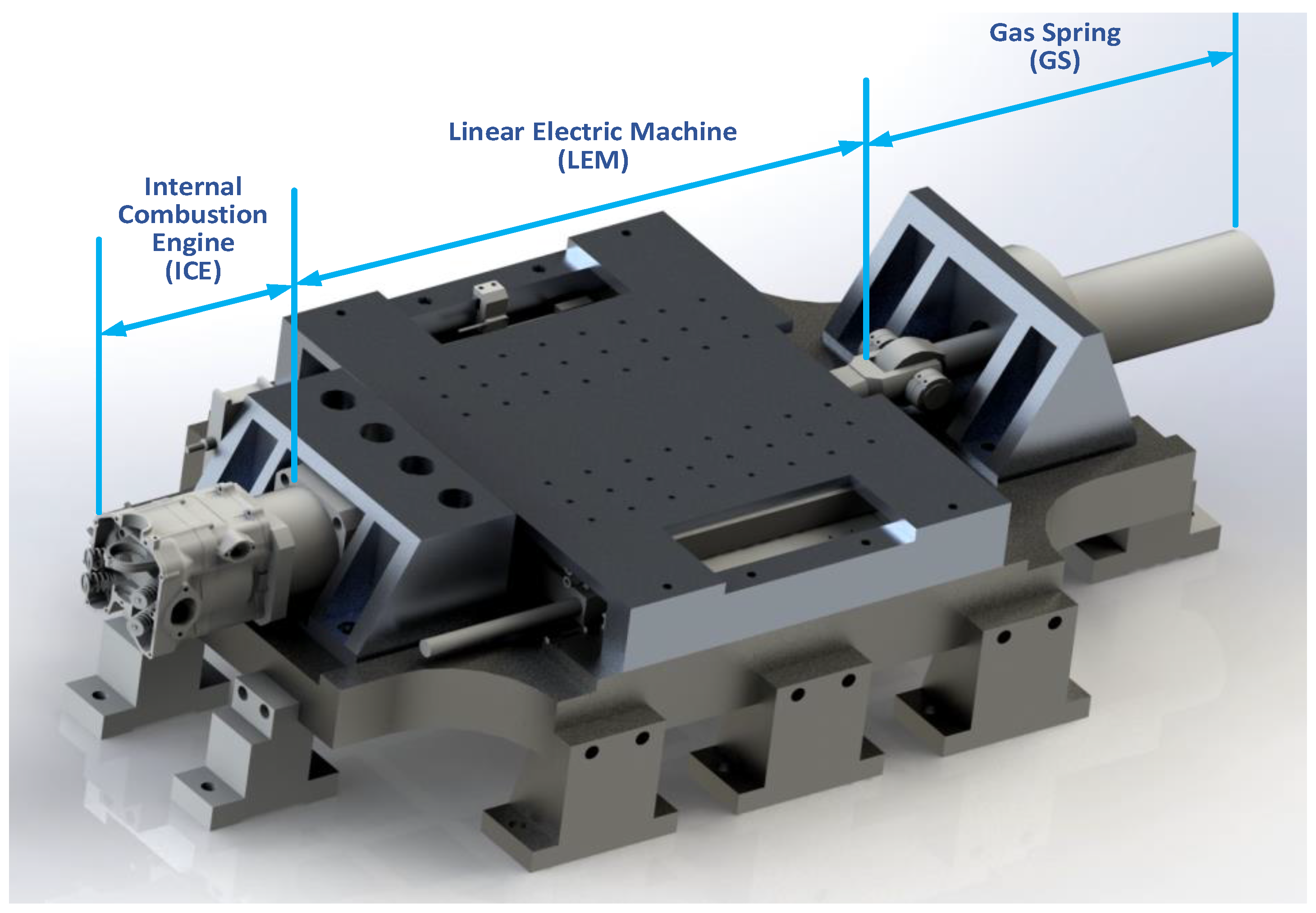
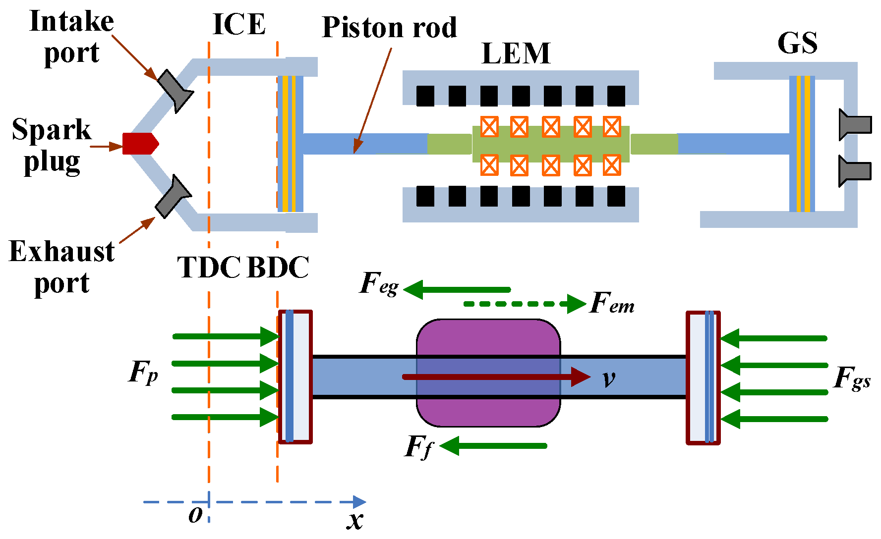
Figure 1 shows the structure of the FPLG studied in this work. It is composed of a GS, a LEM and an ICE. The GS acts as a rebound device. The LEM mover is driven reciprocally to generate electrical power through the coupled consequence of the periodical combustion expansion in ICE cylinder and GS rebounding. The major design specifications are listed in Table 1.
The force distribution of the system can be briefly illustrated in Figure 2, in which the zero reference is set at the starting position of the top dead center (TDC) and the positive direction is from TDC to the bottom dead center (BDC).
At the beginning of the starting process, the piston is located at the TDC position. The LEM functions as a motor and drives the piston towards BDC. The GS is therefore compressed. When the piston reaches the BDC, its velocity decreases to zero. Afterwards, the GS begins expanding and pushes the piston back to TDC. When the piston arrives at the igniting position xign, the ICE is ignited and then the starting phase is completed. The LEM is switched into a stable generating state. The stable generating cycles can be divided into two sub-processes, one is the expansion-generating process from TDC to BDC, and the other is the compression-generating process from BDC to TDC.
When the LEM is operated in motoring mode, the piston dynamics satisfies the equation:
M x ¨ = F e m + F p F g s F f
When the LEM works under stable generating mode, the dynamic equation can be described as:
M x ¨ = F p F g s F f F e g
where Ff is the friction force, and it can be assumed to be proportional to the velocity as follows:
F f = B v v
where Bv is the friction coefficient.

2.1. Linear Electric Machine (LEM) Modeling

2.1.1. LEM Model under Motoring Mode

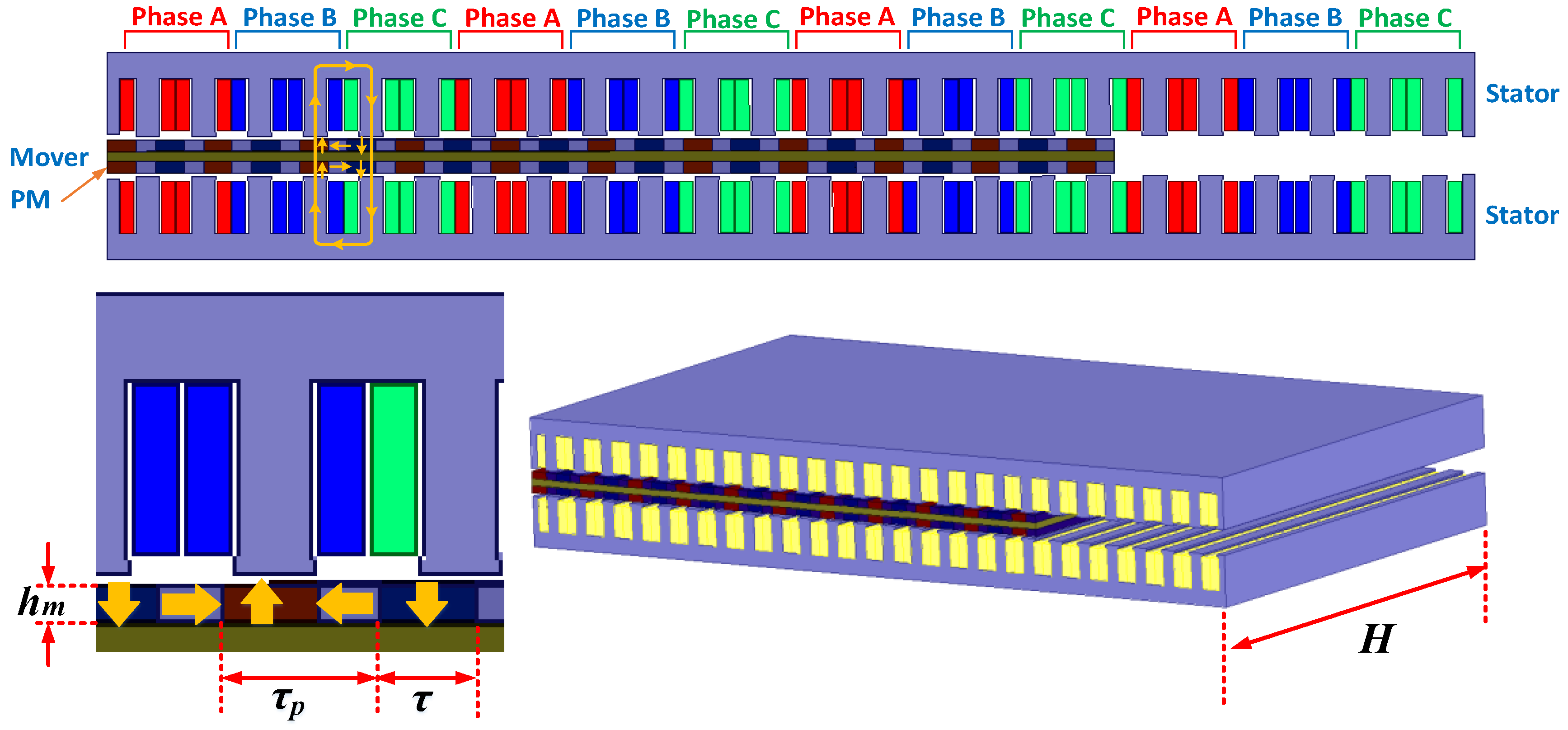
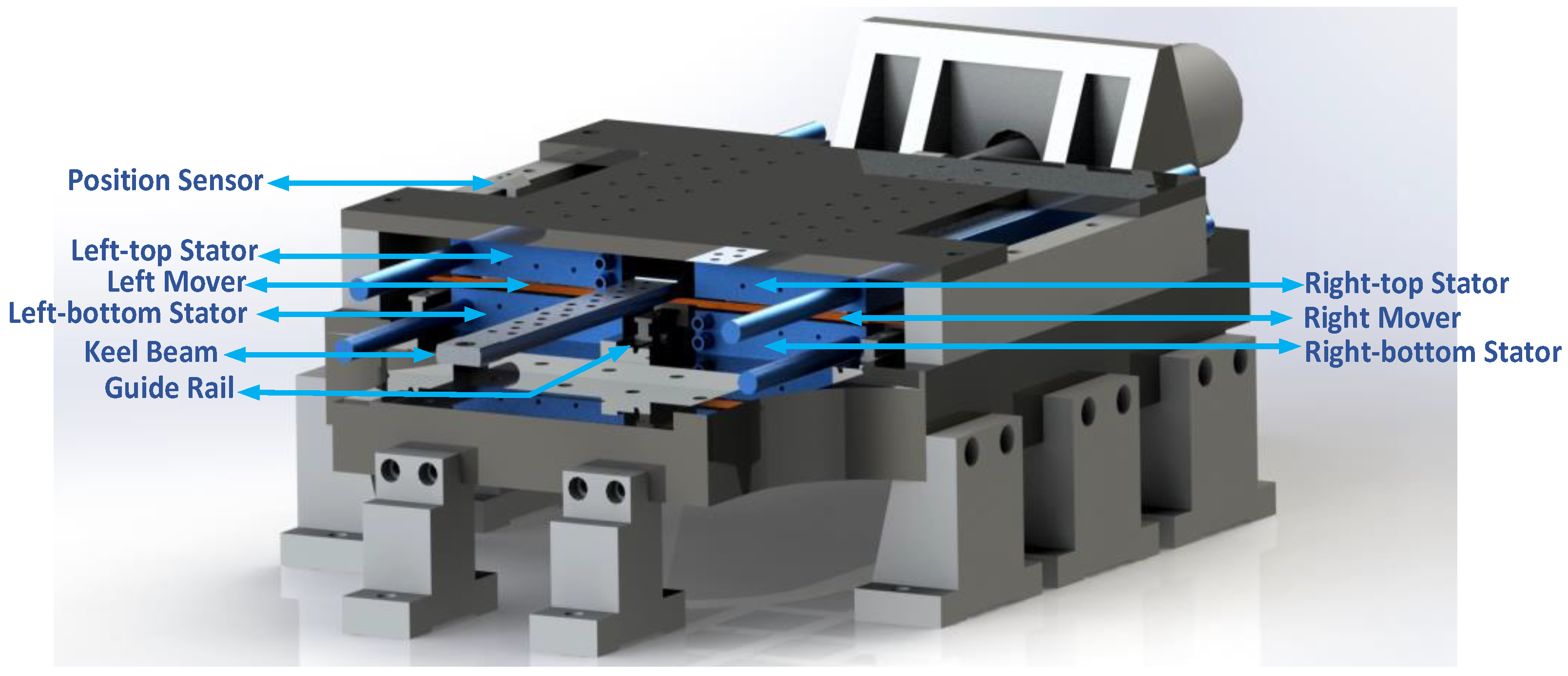
The 3D configuration of the LEM is shown in Figure 3. Two flat-type LEM units are combined together to form a single machine with the permanent magnet mover sandwiched between two stators. This design increases the output electric power and the power density. As shown in Figure 4, permanent magnets with Halbach arrays are mounted on both surfaces of the mover. Each of the upper and lower stators carries a set of three-phase copper windings to be fed with sinusoidal currents. Concentrated windings are implemented to reduce the power loss. Each LEM unit is a 3-phase 21-pole/18-slot flat double-sided moving-magnet permanent magnet synchronous linear machine (PMSLM). A keel beam is assembled between the left and right movers to enhance the stiffness of the entire moving part. The keel beam is supported by a slide guide rail. Two guide rails are also assembled symmetrically on both sides of the mover plate. The mass of the LEM mover is less than 8.5 kg, and it can be further reduced by utilizing the special materials like the carbon fiber. The force constant is 150 N/A. The line-to-line back electromotive force (EMF) coefficient is 87 V/ms−1.
The designed LEM in this work is a surface-mounted PMSLM without salients. The Fem can be accurately controlled by adjusting the coil current. Through d-q transformation [27,28], Fem can be described as:
F e m = 3 π 2 τ p [ ψ f + ( L d L q ) i d ] i q
where τp is the pole-pitch, ψf is the flux produced by the permanent magnet, Ld, Lq, id and iq are the inductances and current of d-axis and q-axis respectively.
The d-axis and q-axis inductances of a surface-mounted PMSLM without saliency approximately equal to the synchronous inductance, i.e., Ld = Lq, the motoring force can be simplified as:
F e m = 3 π 2 τ ψ f i q

2.1.2. LEM Model under Generating Mode

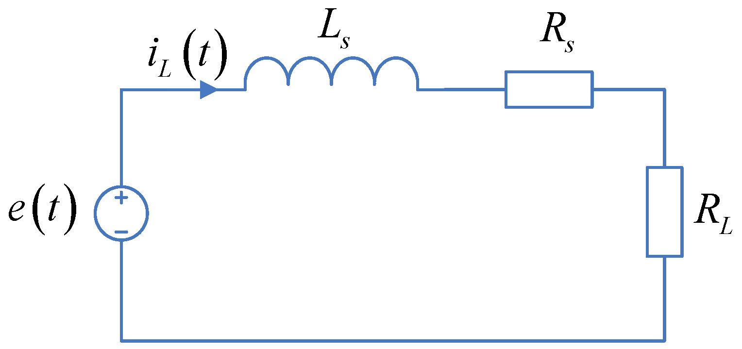
Assuming that the load is resistive, the LEM model can be described by the phase equivalent circuit model shown in Figure 5 [11,18,29].
According to the phase equivalent circuit model, the induced voltage and current can be derived as:
e ( t ) = ( R s + R L ) i L ( t ) + L s d i L ( t ) d t
i L ( t ) = e ( t ) R S + R L ( 1 exp 1 R s + R L t )
where Rs is the phase winding resistance, RL is the load resistance, Ls is the winding inductance.
The back EMF induced in the coil of one phase can be described as:
e ( t ) = H N H c h m μ 0 2 τ p sin ( π x τ p ) d x d t
where H is the length of the coil that cuts magnetic lines, N is the number of winding turns per phase, Hc is the magnetic field strength, hm is the thickness of the PM, μ0 is the vacuum permeability, x is the piston displacement.
The total electromagnetic force can be expressed as [18]:
F e g = 6 H 2 N 2 B m 2 1 R S + R L ( 1 exp R s + R L L s t ) d x d t
where Bm is the maximum air gap flux density which can be calculated through the following equation:
B m = μ 0 g e 4 π H c h m sin ( π τ 2 τ p )
where ge is the effective air gap length, τ is the width of PM.

2.2. Thermodynamics Modeling of Internal Combustion Engine (ICE)

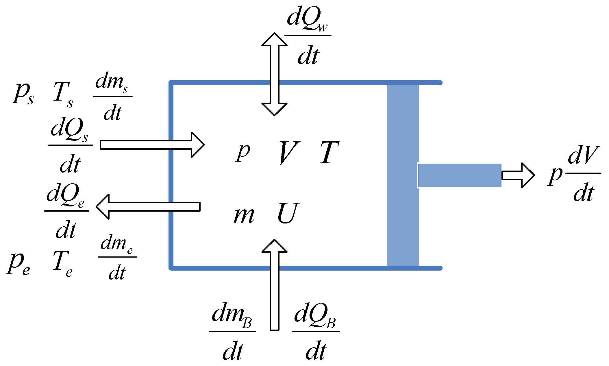
A zero-dimensional single zone model is utilized to build the thermodynamic model [30,31]. Taking the scavenging, compression, combustion, expansion and exhaust processes into account, the in-cylinder states are described in Figure 6, in which the in-cylinder pressure, temperature, refrigerant mass distribution and energy distribution are included.

2.2.1. Description of In-Cylinder Pressure and Temperature

The modeling purpose is to describe the time-dependent pressure and temperature in the cylinder. According to the mass conservation law, energy conservation law and the ideal gas law, the in-cylinder states can be described in the form of the change-rate of the mass and the energy:
d m d t = d m s d t + d m e d t + d m B d t
d U d t = d Q B d t d Q w d t + d H s d t d H e d t p d V d t
p V = m R g T
where m is the total in-cylinder mass of the working medium, ms is the injected mass, me is the exhausted mass, mB is the combusted mass, U is the total in-cylinder energy of the working medium, QB is the heat released in the combustion process, QW is the total amount of heat transfer, Hs is the injected energy, He is the exhausted energy, p is the in-cylinder pressure, V is the working volume of the ICE chamber, Rg is the gas constant, T is the in-cylinder temperature.
It yields from (13) that:
p d V d t + V d p d t = m R g d T d t
The total in-cylinder energy change-rate can be calculated as:
d U d t = m C v d T d t
where Cv is the constant volume specific heat.
The energy change-rate through the intake and exhaust ports can be described in the form of the specific enthalpy as:
d H e d t = h e d m e d t , d H s d t = h s d m s d t
where he and hs are the specific enthalpy of the exhausted and the injected mass.
The change-rate of the in-cylinder temperature and pressure can be derived as:
d T d t = 1 m C v [ d Q B d t d Q w d t + h s d m s d t h e d m e d t p d V d t ]
d p d t = 1 V [ ( γ 1 ) ( d Q B d t d Q w d t + h s d m s d t h e d m e d t ) γ p d V d t ]
where γ is the polytrophic exponent, and:
γ = 1 + R g s C v g
The change-rate of the heat released in combustion is described to be:
d Q B d t = H u g f η c d χ B d t
χ B = 1 exp [ 6.908 ( t t 0 t d ) b 0 + 1 ]
where Hu is the calorific value of fuel, gf is the injected fuel mass per cycle, ηc is the combustion efficiency, χB is the mass fraction burned in the combustion process, t0 is the beginning ignition time and td is the combustion duration, t is the time variable, and b0 is the combustion quality factor.
The total amount of heat transfer mainly consists of three parts including the heat transfer through the cylinder bottom, the top of the piston and the side wall of the cylinder. Therefore, the change-rate of the total heat transfer can be expressed as:
d Q w d t = i = 1 3 d Q w i d t = i = 1 3 h A t i ( T T w g ) = h A t ( T T w g )
where h is the heat transfer coefficient that can be described as follows [18]:
h = 130 V 0.06 ( p 10 5 ) 0.8 T 0.4 ( v 0 + 1.4 ) 0.8
where v0 is the mean velocity of the piston. The cylinder instantaneous volume is determined by:
V = π ( D 2 ) 2 ( S c + S x )
The heat transfer surfaces can be expressed as follows:
A t = A t 1 + A t 2 + A t 3
A t 1 = π D ( S c + S x )
A t 2 A t 3 = π ( D 2 ) 2
where At is the total heat transfer area of the ICE chamber, At1 is the instantaneous side-wall area, At2 and At3 are the equivalent areas of the piston top and cylinder bottom.

2.2.2. Description of Compression and Expansion Processes

Because there is no combustion heat released, no intake and exhaust processes during the compression and expansion processes, the mass change-rate of the working medium in cylinder is considered zero as follows:
d m s d t = 0 , d m e d t = 0 , d m B d t = 0 , d m d t = 0
Therefore, from (17) and (18), the variation of the time-dependent pressure and temperature in the cylinder during the compression process can be described as:
d T d t = 1 m C v [ h A t ( T T w ) p d V d t ]
d p d t = 1 V [ ( γ 1 ) h A t ( T T w ) γ p d V d t ]
where Tw is the temperature of the cylinder wall.

2.2.3. Description of the Combustion Process

During the combustion process, the total mass change of working medium in cylinder is only caused by the combustion. Therefore, the change-rate of the in-cylinder mass can be simplified as below:
d m s d t = 0 , d m e d t = 0 , d m d t = d m B d t
The change-rate of the in-cylinder temperature and pressure can be described as:
d T d t = 1 m C v [ H u g f η c d χ B d t h A t ( T T w ) p d V d t ]
d p d t = 1 V [ ( γ 1 ) ( H u g f η c d x B d t h A t ( T T w ) ) γ p d V d t ]

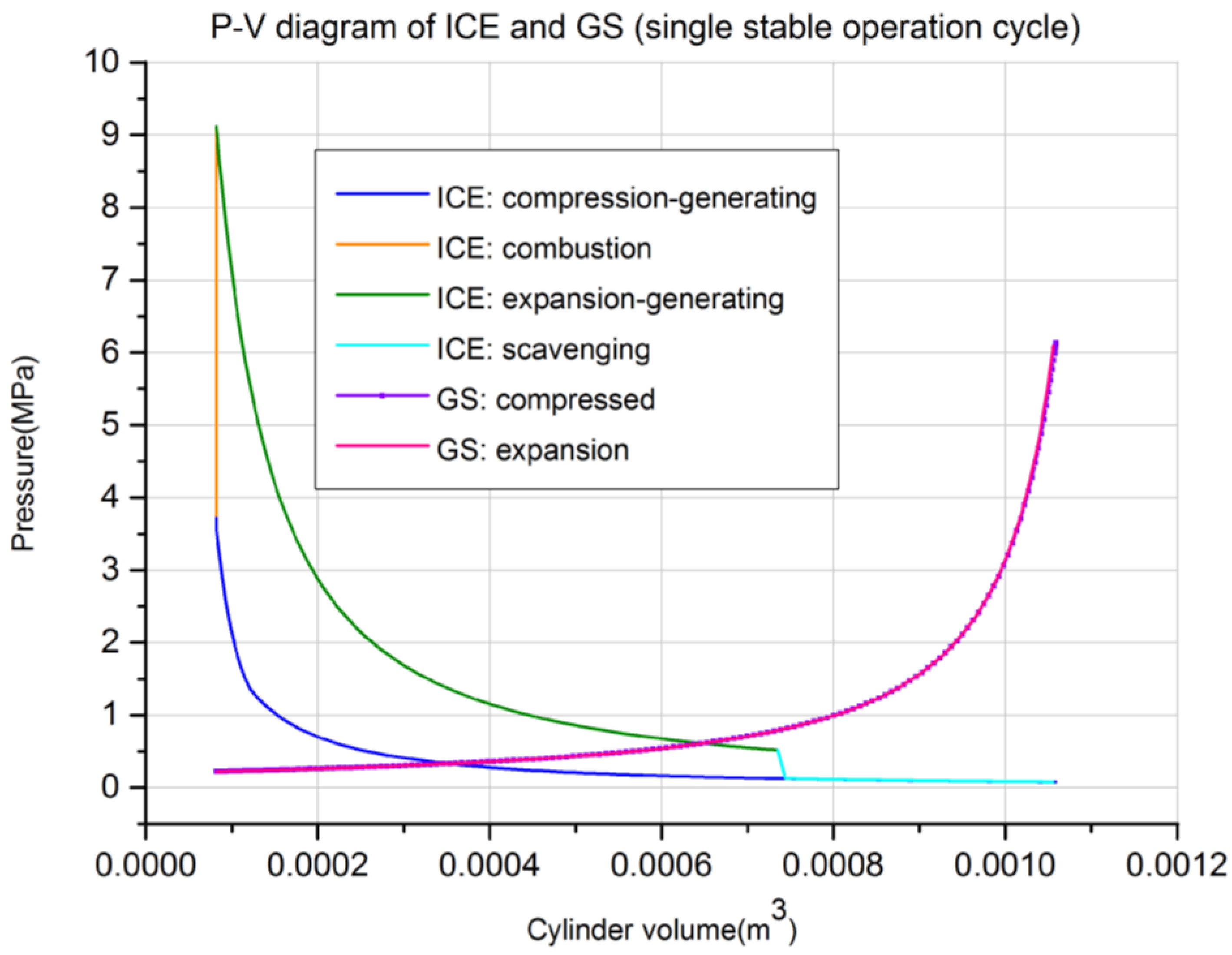
2.3. Gas Spring (GS) Modeling

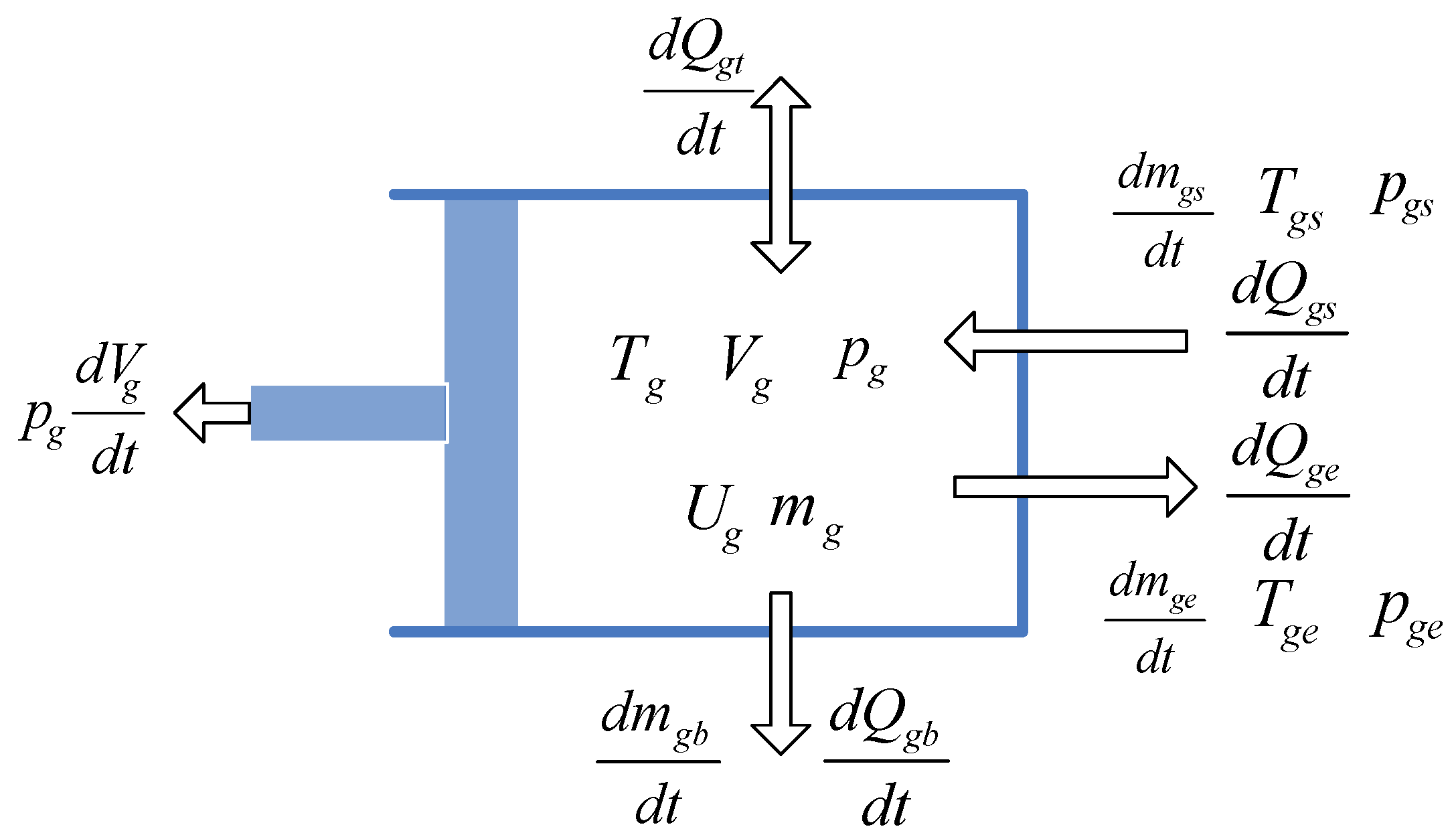
Figure 7 shows the GS model, which illustrates the states in GS chamber. The GS modeling process is similar to that of the ICE except that there is no combustion process in the GS chamber [32].
The change-rate of the temperature and pressure in the GS chamber can be expressed as:
d T g d t = 1 m g C v g [ h g s d m g s d t h g e d m g e d t h g A t g ( T g T w g ) p d V g d t ]
d p g d t = 1 V g [ ( γ 1 ) ( h g s d m g s d t h g e d m g e d t h g A t g ( T g T w g ) ) γ p d V g d t ]
where Tg is the temperature of the GS chamber, mg is the total mass of the working medium in the GS, Cvg is the constant volume specific heat of the working medium in GS, mgs is the injected mass in the GS, mge is the exhausted and leakage mass of the GS, hgs and hge are the specific enthalpy of the injected mass and exhausted mass, hg is the heat transfer coefficient, Atg is the total area of heat transfer of the GS chamber, and Twg is the temperature of the GS cylinder wall.
The instantaneous volume of the GS chamber and the change-rate of the volume are described by:
V g = π ( D g 2 ) 2 ( S c g + x )
and the instantaneous heat transfer surface of the GS chamber can be expressed as:
A t g = A t g 1 + A t g 2 + A t g 3
A t g 1 = π D g ( S c g + x )
A t g 2 A t g 3 = π ( D g 2 ) 2
where Atg is the total heat transfer area of the GS chamber, Atg1 is the instantaneous side-wall area, Atg2 is the equivalent area of the piston top and Atg3 is the area of the cylinder bottom.

3. Full Cycle Operation Strategies and Coupling Simulation System

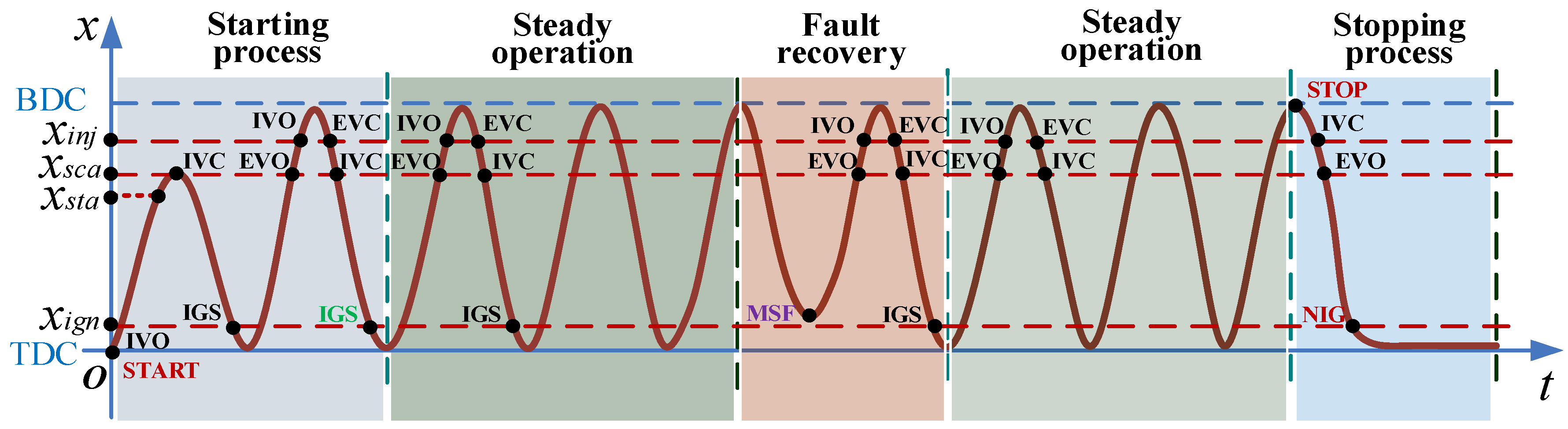
3.1. Full Cycle Operation Processes

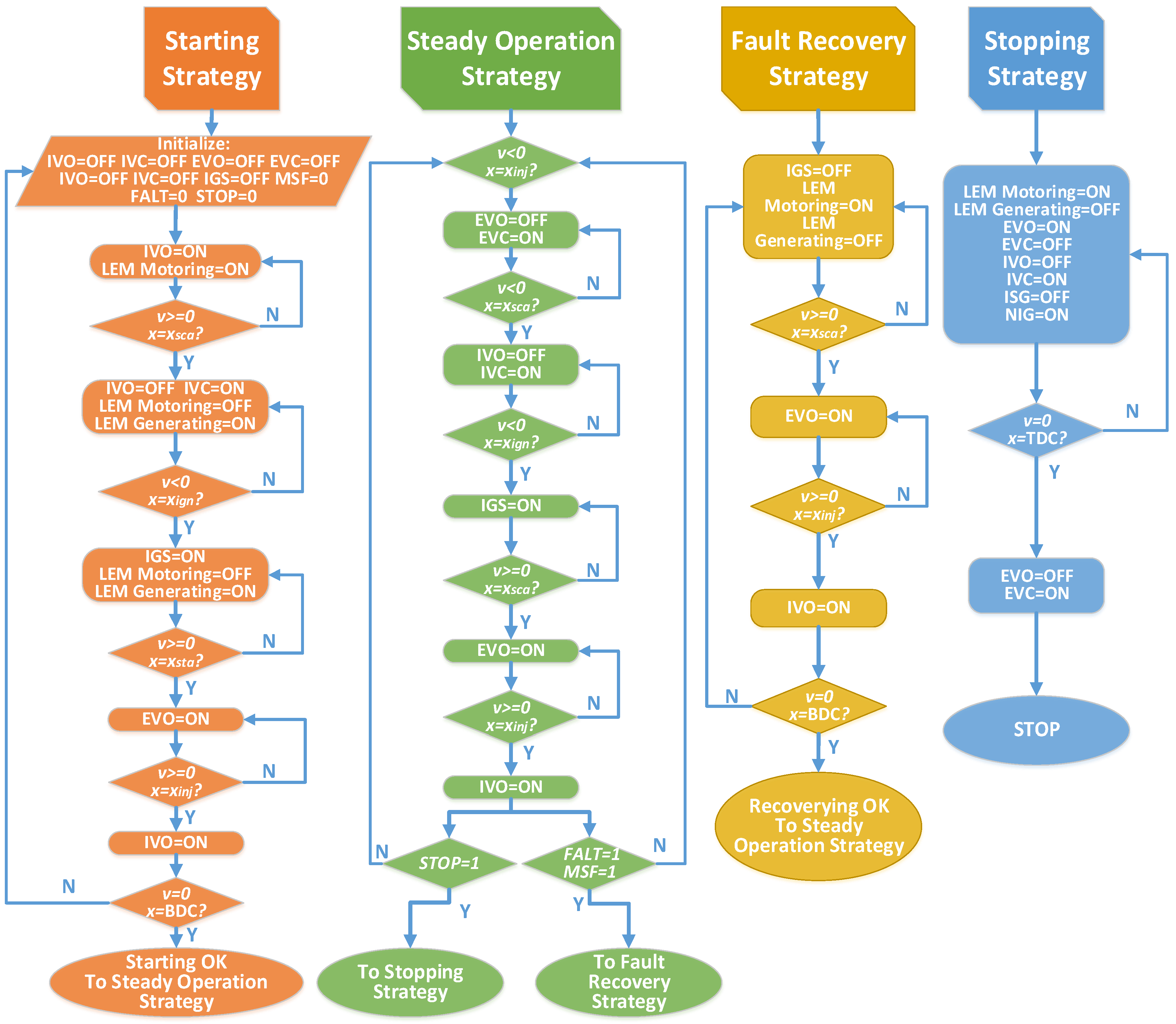
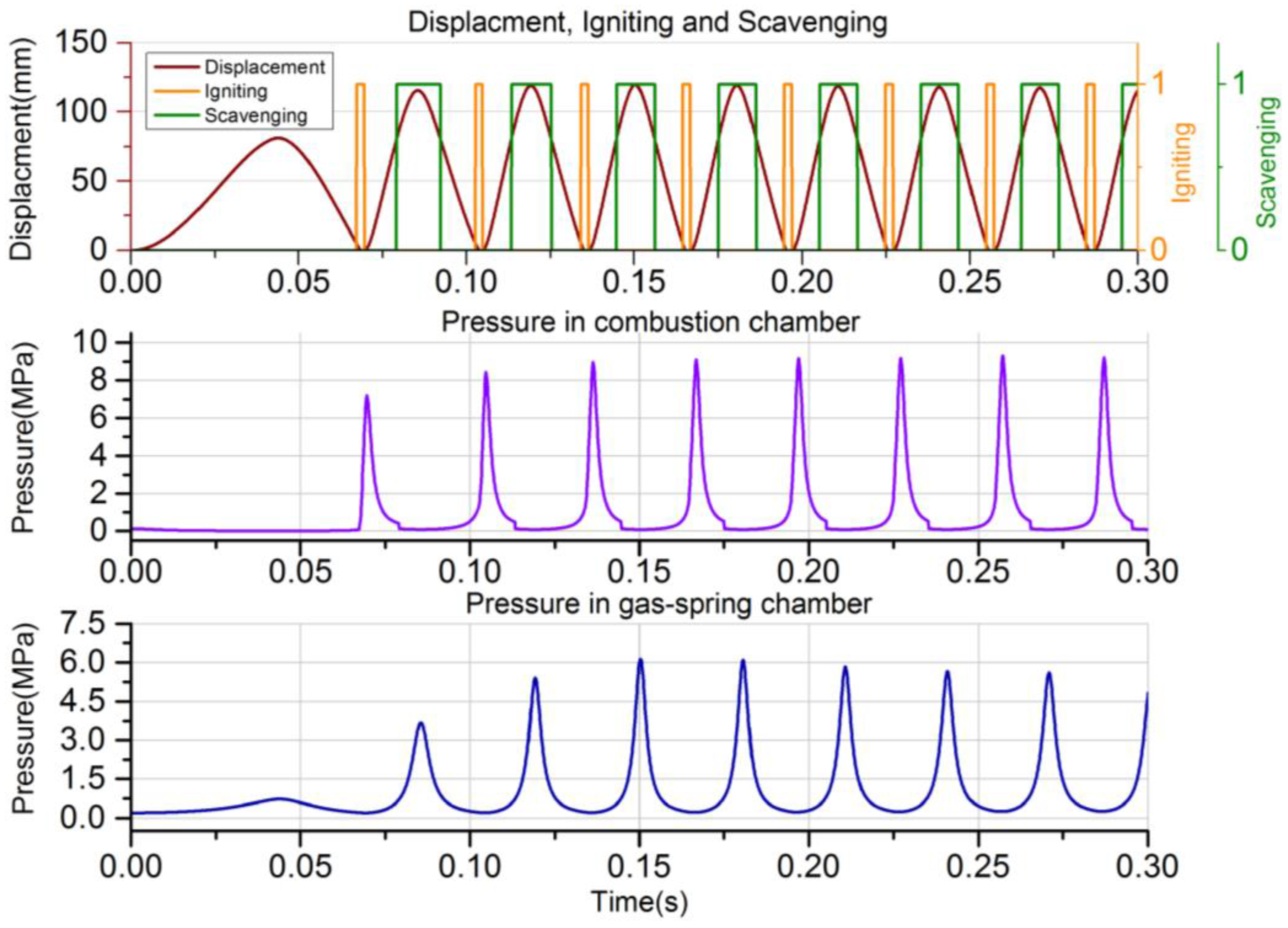
Figure 8 depicts several possible operational states of the FPLG system, including starting process, steady operation, fault recovering and stopping process. Accordingly, the basic operational strategies for various operational states are shown in Figure 9. Particularly, the exhaust valve open (EVO) and the intake valve close (IVC) timing are defined at the same scavenging position xsca during expansion and compression processes. The intake valve open (IVO) and the exhaust valve close (EVC) timing are defined at the same position xinj during the expansion and compression processes.
(1) Starting strategy
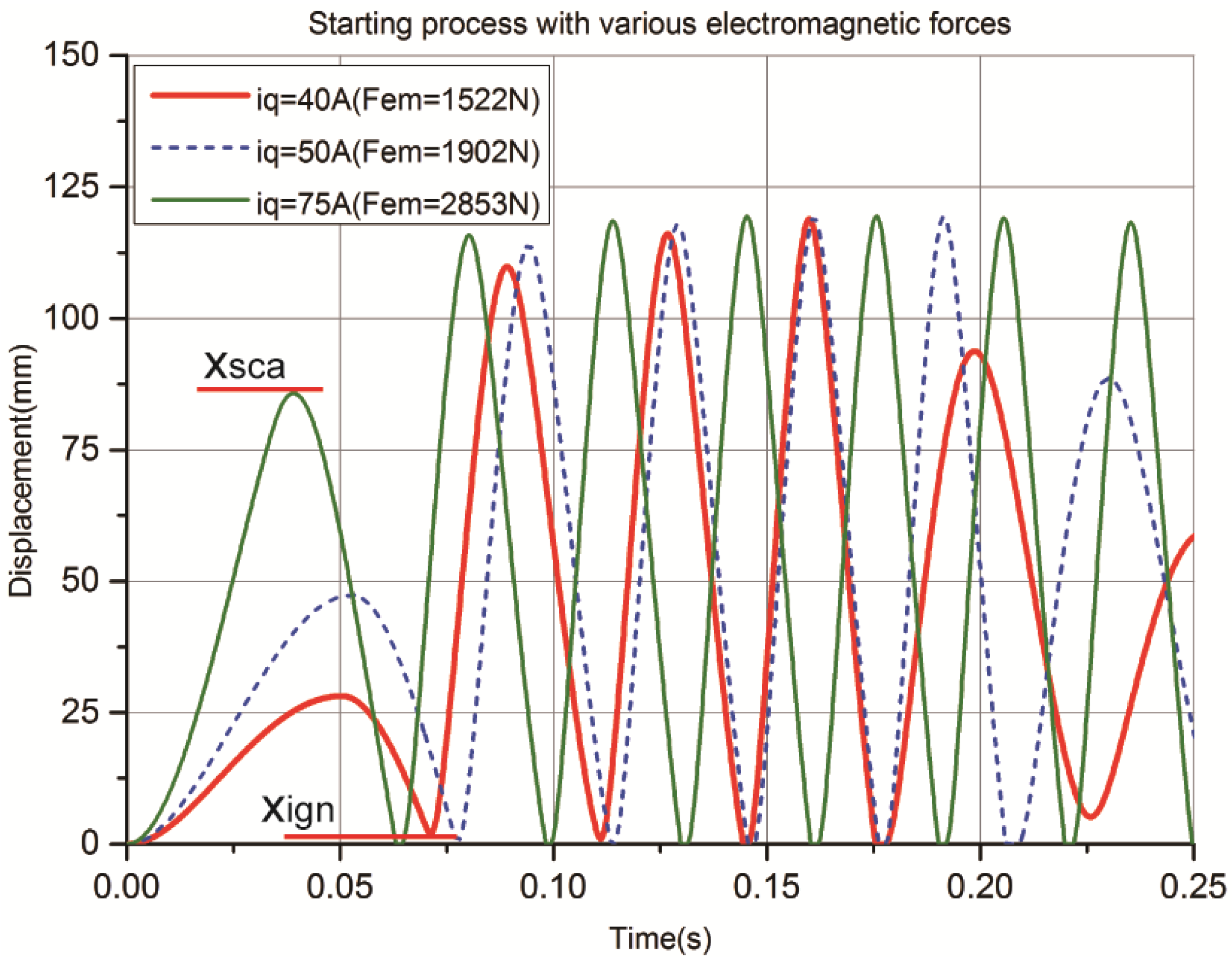
The LEM is operated in motoring mode when starting the FPLG from stationary status. Assuming that there is no burned gas in the cylinder and both the intake and exhaust valves are closed at the ending of the previous stopping process. As the premixed combustion mode is adopted, the intake valve is opened and the premixed flammable gas is sprayed into the ICE cylinder at the beginning of the starting process. The piston is driven from TDC to BDC by the electric motoring force, meanwhile the GS is compressed.
When the piston arrives the critical starting position xsta, the intake valve is closed and the LEM is switched to generating mode. The piston accelerates towards TDC mainly by the GS rebounding force. When it reaches the igniting position xign, the first ignition starts. After that, the piston is driven by the combustion expansion force and moves towards BDC. When it gets to the scavenging position xsca, the exhaust valve is opened.
When the piston moves forward to the injecting position xinj, the intake valve is opened. If the piston can reach the position of BDC, which means that it satisfies the necessary condition of next ignition. When it continues moving to the position xinj from BDC to TDC, the exhaust valve is closed.
When it again moves to the xsca position, the intake valve is closed. If the piston can continue reaching the xign position and if the ICE can be ignited successfully, it means that the system is started successfully and it turns into steady operation. Otherwise, it needs to be started again by repeating the operations described above.
(2) Steady operation strategy
Under steady operation, the valves control is simple and the valves timing is relatively fixed. During the expansion-generating stroke from TDC to BDC, if the piston moves to xsca, the exhaust valve is opened. If the piston arrives at xinj, the intake valve is opened. While during the compression-generating stroke from BDC to TDC, when it reaches the xinj position again, the intake valve is closed. Once the piston moves to xsca again, the intake valve is closed. If the piston reaches xign, the igniting signal is on and the ICE is ignited. After that, it turns into the next stable operation cycle with the same valves control mentioned above.
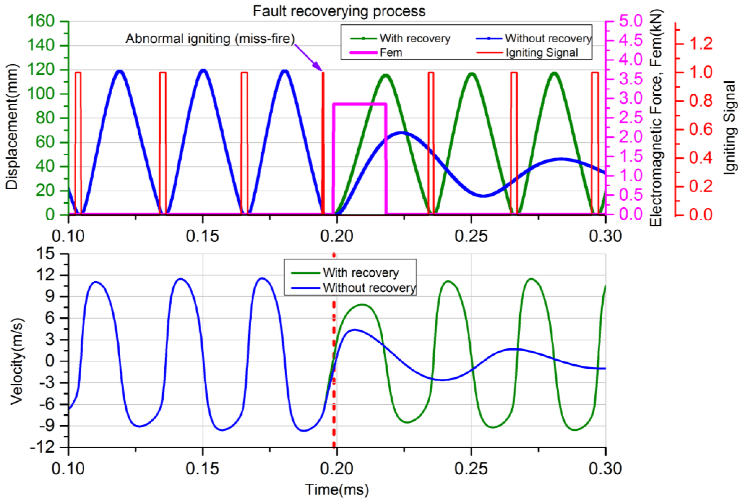
(3) Fault recovery strategy
When unstable operation occurs, e.g., when a missfire happens, the system must be recovered as soon as possible to avoid the influence of next stable operation cycle. As shown in Figure 8, if the piston fails reaching the xign position, miss-fire will be caused. Therefore, the piston will have no enough expansion kinetic energy to reach xsca, let alone the xinj position and the BDC position. In this case, the LEM must be switched to motoring mode as an auxiliary kinetic energy provider to guarantee the piston capable of reaching the xsca position and the scavenging process being carried out successfully. Once the piston can reach xsca position, the LEM is changed to generating mode again. If the piston can reach the BDC position, it means that the recovery process is successful and the system can maintain steady operation.
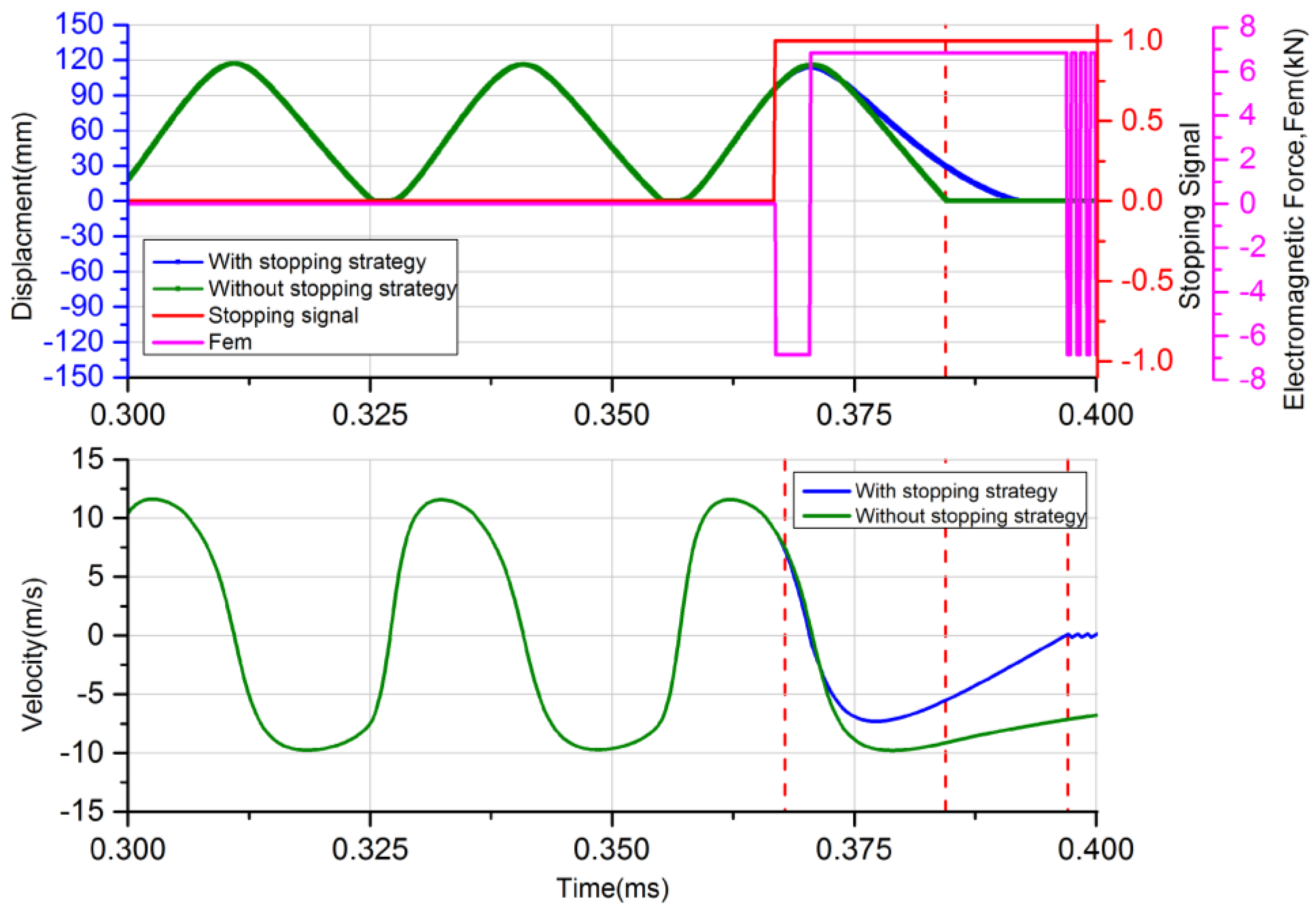
(4) Stopping strategy
During the stopping process, the LEM must be operated as a motor to avoid the piston top hitting the cylinder header. As shown in Figure 8, if the controller receives a stopping signal during the compression-generating stroke from BDC to TDC, the intake valve is closed once the piston arrives at the xinj position.
When the piston moves to xsca, the exhaust valve is opened. If it gets to xign, the igniting signal is no longer enabled. The piston is driven to TDC with the velocity settling to zero and the system can be stopped safely and reliably.

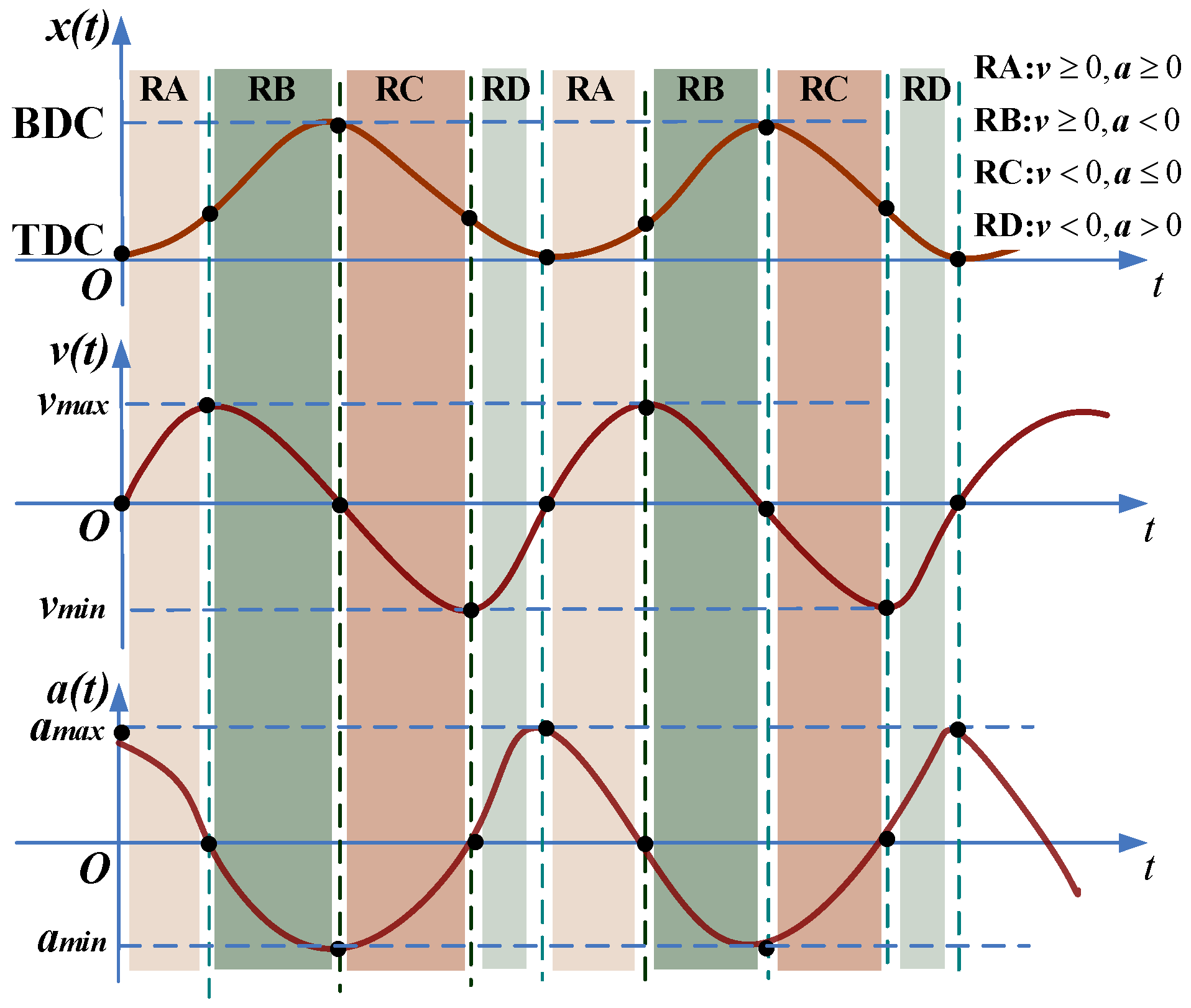
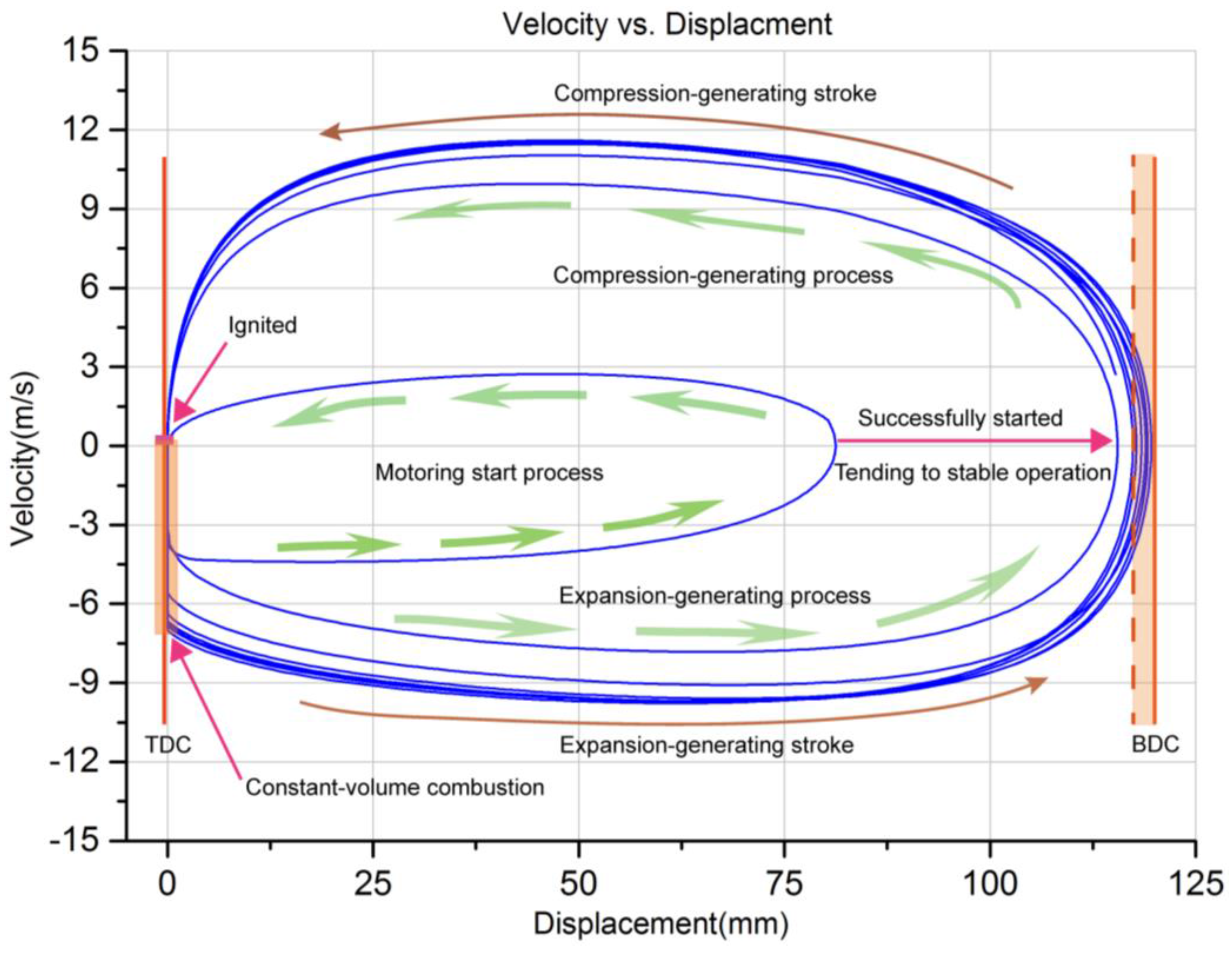
3.2. Motion States Monitoring

As introduced above, monitoring of the piston motion states is essential to realize stable operation. On the one hand, the TDC position must be controlled precisely to ensure a sufficient compression ratio for successful ignition and efficient combustion. This can also avoid excessive in-cylinder pressure and prevent mechanical contact between the piston top and cylinder header. The BDC position also should be controlled to ensure efficient scavenging operation. On the other hand, the operation of the intake and exhaust valves are highly dependent on the pre-judgement of the piston motion states such as the displacement, velocity and acceleration. Moreover, the piston motion states have significant effects on the system performances like the power and efficiency [13,25].
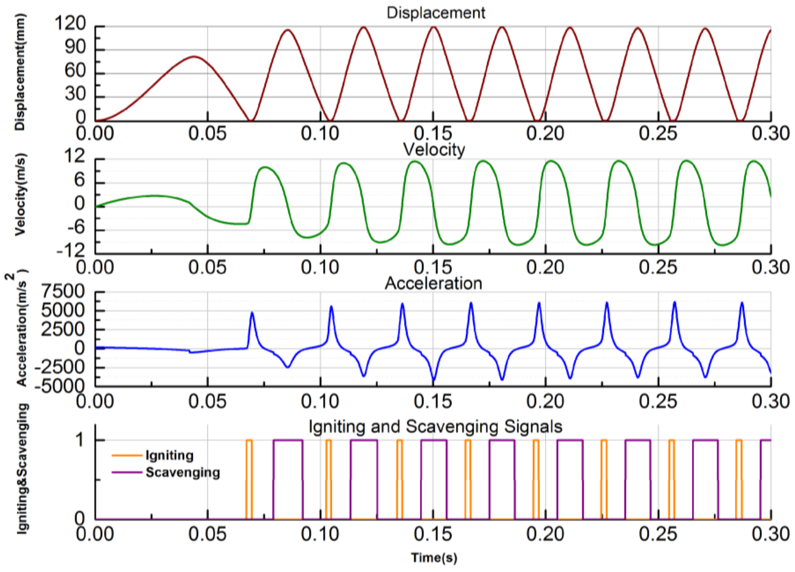
According to the feedbacks of the position sensor, the piston motion states during the stable operation can be divided into four phases as shown in Figure 10. The characteristics of each process can be summarized as follows.
RA: x (TDC→BDC), v ≥ 0 and a ≥ 0, early expansion-generating process. At the beginning of each stable cycle, after ignition, the acceleration is the maximum, and the piston accelerates from TDC to BDC. When the pressure in ICE cylinder equals to that in the GS chamber, the acceleration becomes zero and the velocity reaches the maximum value.
RB: x (TDC→BDC), v ≥ 0 and a < 0, later expansion-generating process. The piston slows down gradually under the GS rebounding force. When the piston arrives at BDC, the velocity drops to zero and the acceleration is the negative maximum value.
RC: x (BDC→TDC), v < 0 and a ≤ 0, early compression-generating process. The piston rebounds and accelerates from BDC to TDC by the GS. When the pressure in ICE and GS is equal again, the piston acceleration is zero and the velocity reaches its negative maximum value.
RD: x (BDCTDC), v < 0 and a > 0, later compression-generating. The piston begins slowing down towards TDC till the next ignition occurs.
These four phases are the key pre-judgement criteria of the piston motion states, with which the valves, ICE and the piston motion control can be implemented successfully.

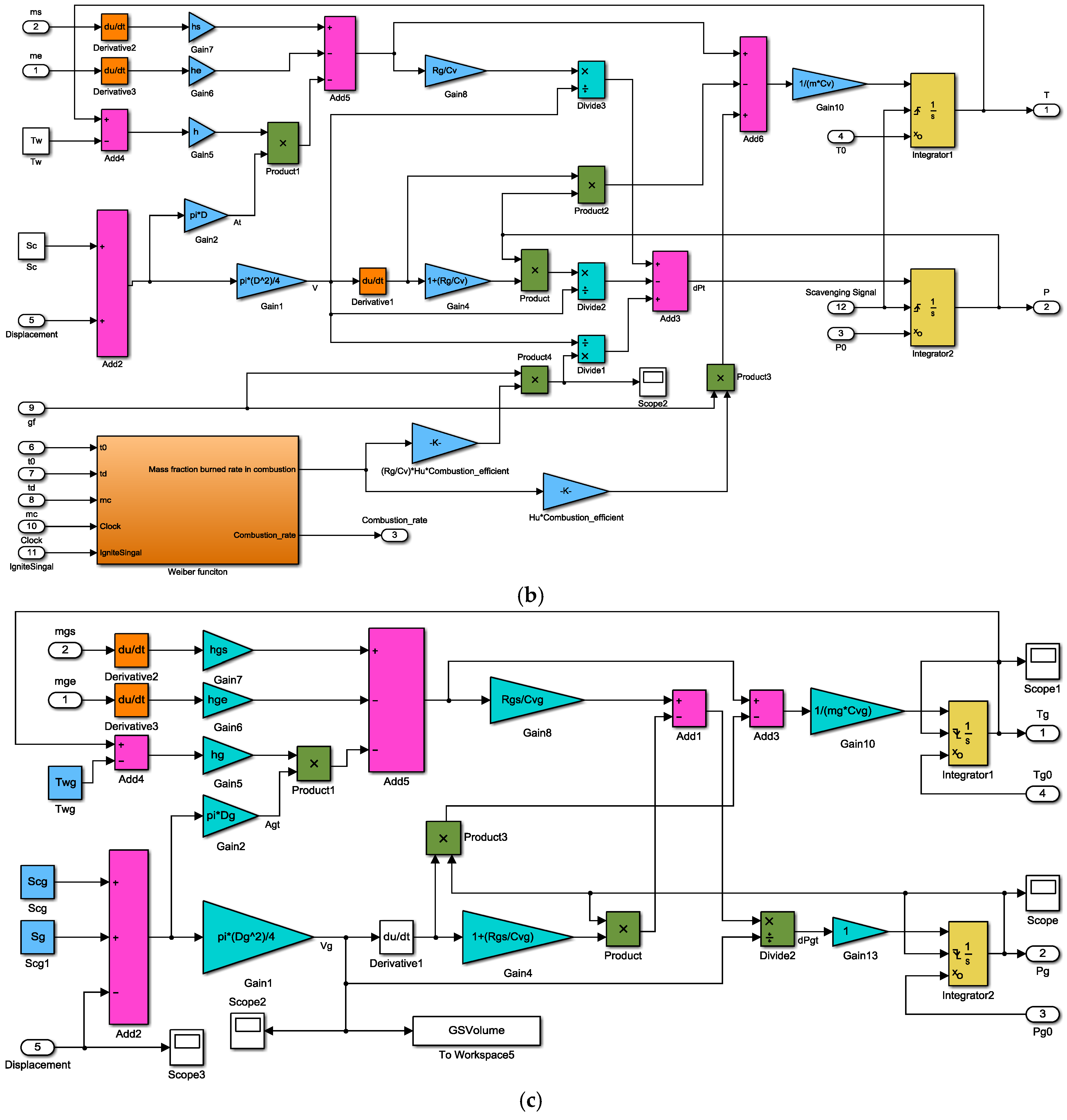
3.3. Coupling Simulation Model

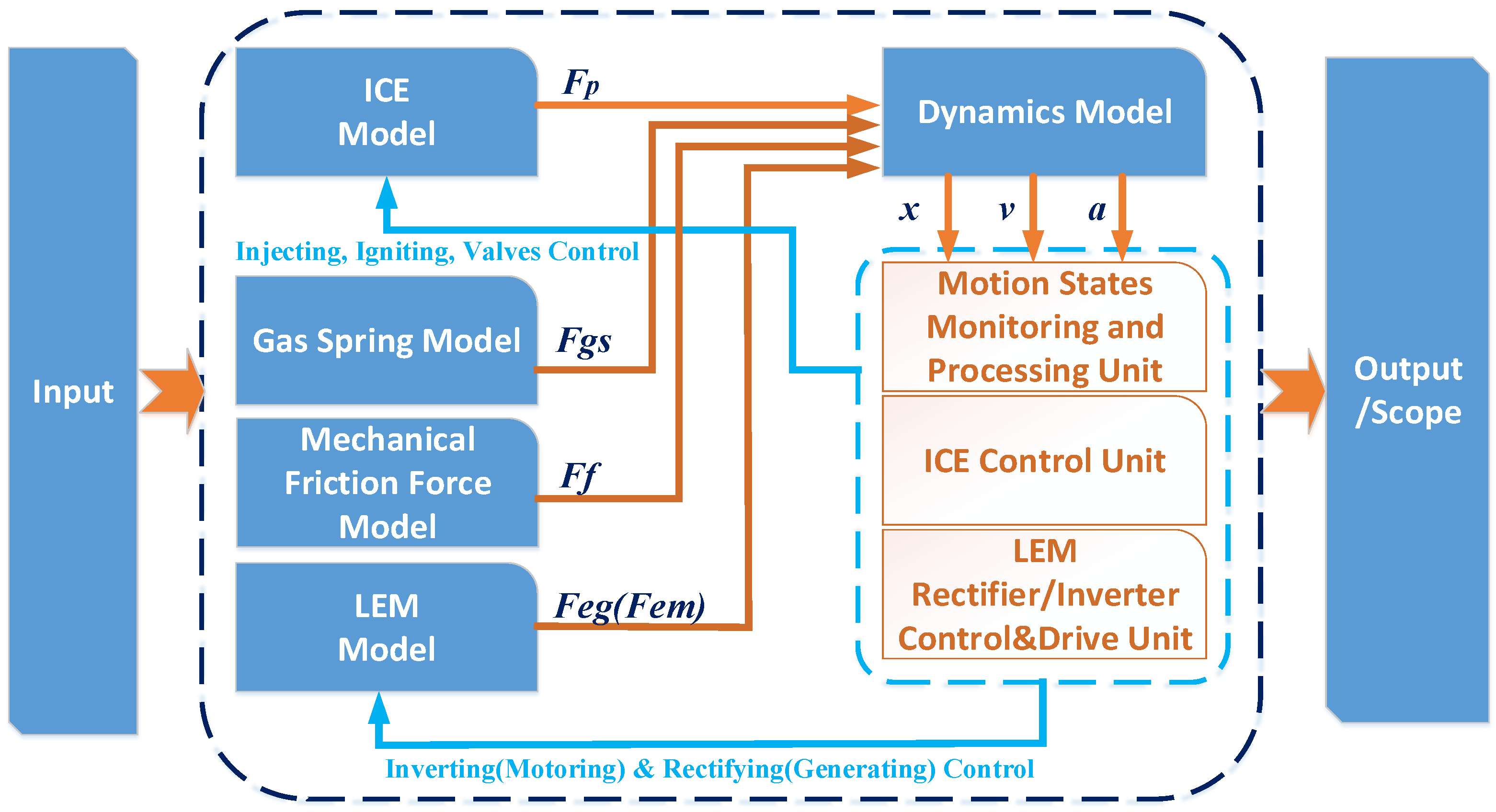
The Matlab/Simulink simulation model is established based on the mathematical models. 
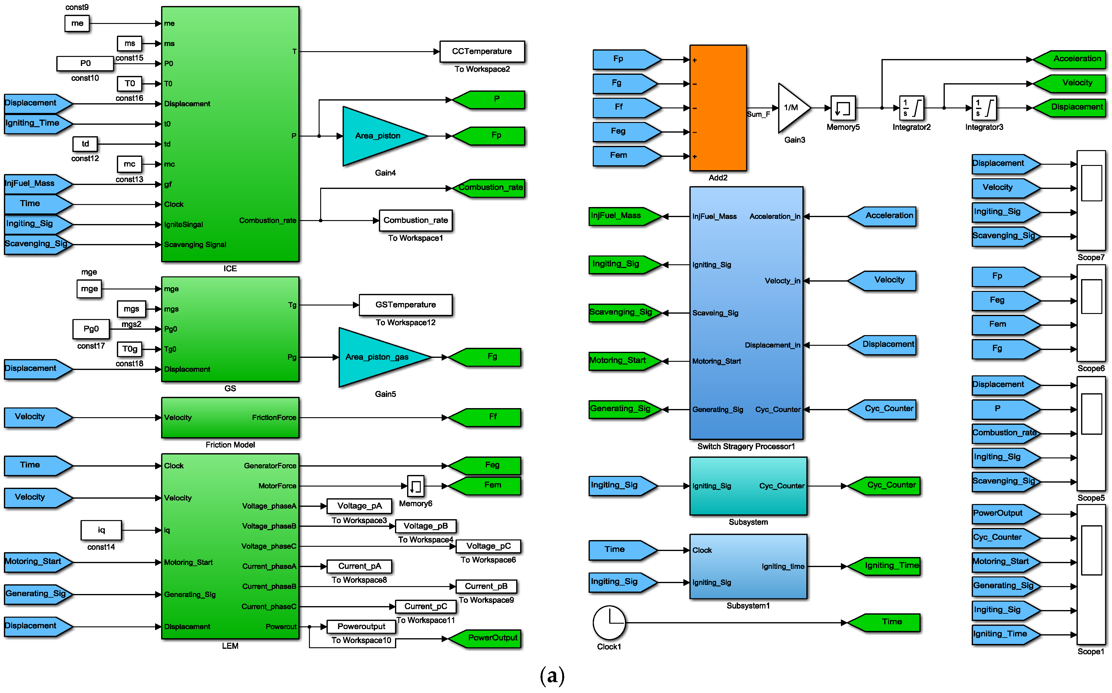
Figure 11 shows the diagram of the simulation model, in which the sub-models of the ICE, GS and LEM, the mechanical friction model, the dynamics model, the motion states monitoring unit and the control strategy processing unit are included. Figure 12a shows the entire simulation model. Figure 12b,c illustrates the sub-models of the ICE and GS. The LEM simulation model is developed with S-function block. Table 2 lists the major simulation conditions. The key structural parameters of the ICE and GS are identical. The critical starting position xsta, the scavenging position xsca and the injecting position xinj are defined at the same point x = 85 mm.

4. Dynamic Characteristics and Performance Analysis under Various Control Strategies

4.1. Starting Process Analysis with the Starting Strategy

There are three major factors that determine whether the system can be started successfully or not. The first is whether the ignition operation can be carried out, i.e., whether the piston can reach the ignition position xign. The second is whether the in-cylinder states such as the temperature and pressure at the moment of ignition are sufficient for abundant combustion to release enough heat and push the piston to the BDC position. The third is whether the motion frequency is near the system natural frequency. The motion frequency must be beyond the range of the system natural frequency.
Figure 13 shows the starting process with various constant motoring currents using the starting strategy introduced above. It states that when the motoring force is FEm = 2853 N, the piston can be driven to the critical starting position xsta (xsta = xsca), where the intake valve can be closed successfully and the energy stored in the GS is sufficient to rebound the piston back to the TDC position, so that the first ignition can be conducted successfully and the fuel can be burnt sufficiently to propel the piston to the BDC position. Then the following EVC, IVC and IGS operations can be carried out successfully. The starting process lasts about 62.5 ms (about two cycles) and afterwards the system smoothly turns to steady operation.
While under 1902 N or 1522 N motoring force, the piston cannot reach the critical starting position. Though the energy stored in the GS can rebound the piston to the xign position, the in-cylinder states at the igniting moment are not sufficient for abundant combustion. Therefore, after the first ignition, the piston cannot reach the defined BDC position, so that the rebounding stroke decreases. This situation results in the reduction of the duration of the compression process and an increase in the motion frequency. Accordingly, the ignition frequency will be enhanced. Even though the piston can reach the BDC and TDC positions again, the gap between the actual motion frequency and the system natural frequency is gradually enlarged. Ultimately, with the accumulation of cycle-to-cycle variations, the piston displacement increases gradually in each expansion stroke. Under this circumstance, unstable operation easily happens after several cycles.

4.2. Dynamics Characteristics of the Stable Operation

After the starting process, the system operates in a stable state with the steady operation strategy. Figure 14, Figure 15 and Figure 16 show the simulated dynamic responses of the FPLG system from the starting process to the stable operation.
Figure 14 shows the piston displacement, velocity, acceleration, and the ignition and scavenging signals. Because the equivalent stiffness profile of the ICE and GS are different, during the expansion-generating stroke and compression-generating stroke, the motion profile is not symmetrical. The maximum displacement xmax = 119.6 mm, and the equivalent compression ratio ε = 12.96. The maximum velocity of the expansion-generating stroke vemax = 12 m/s, while in the compression-generating stoke, it is about 10 m/s, or vcmax = 10 m/s. When the piston arrives at the predefined ignition position xign = 5 mm, the ignition signal is enabled. When it moves up to the predefined scavenging position xsca = 85 mm, the scavenging signal is enabled. After the moment of ignition, the acceleration increases dramatically, and can even reach about 6250 m/s2. The average cycle duration Tav = 29.4 ms, thus, the simulated motion frequency fm is about 34.01 Hz.
Figure 15 shows the force curves. At the TDC position, the force generated by the ICE in-cylinder pressure reaches its maximum value which is about 77.69 kN. At the BDC position, the force produced by the GS pressure achieves its peak value of 50.15 kN. At the stable generating cycles, the electromagnetic force is opposite with the velocity as a resistant force, and the maximum value Fegmax = 4507 N. The maximum friction force is about 140 N, which is much smaller than the force generated by the in-cylinder pressure.
Figure 16 shows the pressure profiles. At steady operation, when the piston is around the TDC position and after the ignition moment, the maximum in-cylinder pressure pmax = 9.5071 MPa. At the BDC position, the maximum GS pressure pgmax = 6.1372 MPa.
The velocity versus displacement is illustrated in Figure 17. It shows that after two cycles, the system successfully enters stable operation. The maximum displacement value of the piston increases gradually and operation eventually becomes stable. Owing to the elimination of the crankshaft, the free-piston motion is completely determined by the resultant force applied on the piston-rod as shown in Figure 2. Because of the slight difference of the injected fuel mass and the igniting time, the combustion variation in each cycle is thus inevitable and the elastic potential energy stored in the GS is not always consistent.
Figure 18 shows the P-V diagram of the ICE and GS during a single operation cycle. It obviously shows that the GS pressure profile is nearly the same during both the expansion-generating and compression-generating strokes, while the ICE pressure changes dramatically due to the in-cylinder combustion. The combustion is a constant-volume process, i.e., the combustion process can be considered to be completed instantaneous so that the pressure increases dramatically. The initial pressure of GS is 0.2 MPa, and the peak pressure is 6.1372 MPa. The initial pressure of ICE depends on the pressure at the ending of the scavenging process, which is close to the outside atmospheric pressure.
Figure 19 shows the three-phase voltage, current and electric power output performances of the FPLG system. The peak phase voltage Umax is about 462 V, and the phase current is no larger than 75 A. During the starting process, the LEM works as a starting motor and drives the piston to the ignition position, which lasts for about 42 ms. After the first ignition, the LEM functions as a generator and produces electric energy. Because the velocity of the expansion-generating process is larger than that of the compression-generating process, the output electric power during the expansion-generating stroke is larger than that during the compression-generating stroke. The simulated maximum electric output power PEmax = 52.57 kW, and the mean power PE = 26.36 kW. The simulated overall efficiency ηeff = 36.32%, which is higher than the design objective.

4.3. Fault Recovering Process

Figure 20 shows the simulated fault recovery process for the common unstable operation caused by misfiring. When an unstable operation happens, the piston keeps moving to the BDC pushed by a constant electromagnetic force about 2850 N generated by the LEM. The unstable operation can be soon recovered during one cycle duration of less than 20 ms, and has almost no influence on the next stable cycle.

4.4. Stopping Process

Figure 21 shows the comparison results of the stopping process with and without the stopping strategy. In the situation without stopping strategy, when the stopping signal is enabled, the LEM still operates in generating mode, but both the igniting and injecting signals are disabled. The piston slows down with the combined actions of the generating resistant force and mechanical friction. It shows that the piston arrives the TDC position with nonzero velocity, which will make the piston top hit the cylinder header.
On the other hand, with the stopping strategy, once the stopping signal is enabled, the LEM functions as a braking motor which provides braking force to slow down the piston. The piston stops at the TDC position with zero velocity within less than 30 ms (Tstp < 30 ms). It validates that the system can be stopped faster and more reliably with the stopping strategy.
As a summary, the major performance specifications are listed in Table 3.

5. Conclusions

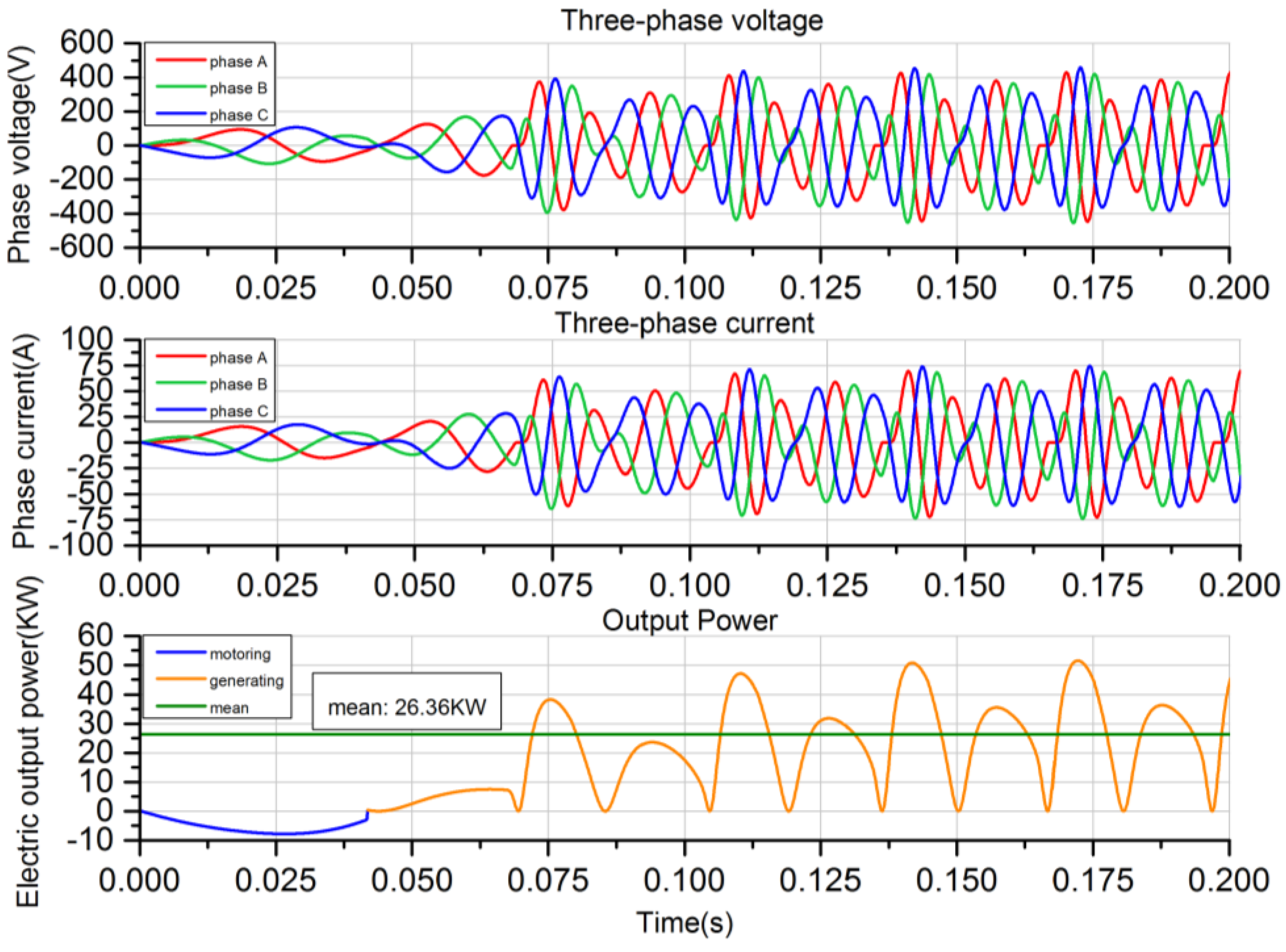
With the developed full cycle simulation model, the top-level systemic control strategies including the starting, stable operating, fault recovery and stopping strategies are conveniently analyzed and discussed. In addition, the FPLG system behaviors under various operation situations are evaluated. The analysis indicates that the proposed full cycle operation strategies are plausible, and the simulation performances like the generating electric power and overall system efficiency meet the expectations. Besides, the feasibility of the top-level strategies are validated. The system can be successfully started during a single motion cycle in less than 100 ms, when the piston is driven to 85 mm away from the TDC position with a constant 2853 N motoring force. With the proposed steady operation strategy, the system can run stably and robustly. The effective electric output power can reach 26.36 kW, with an overall system efficiency of 36.32%, when the motion frequency is 33.74 Hz and the equivalent compression ratio is 12.9. Importantly, once an unstable operation like a misfire occurs, with the proposed fault recovery strategy, the system can smoothly transit to the next stable cycle immediately, which only takes less than 20 ms. With the proposed stopping strategy, the system can be stopped more fast and reliably taking less than 30 ms, which is beneficial for avoiding mechanical contact with the cylinder header. Our future work will be focused on the prototype development and verification of the control strategies through experimental tests, and also on the optimization of the performance.

Acknowledgments

This work is supported by the International S&T Cooperation Projects of China (Grant No. 2014DFA71010); National Science and Technology Support Project (2014BAF10B00); Natural Science Foundation of Ningbo (No. 2015A610144). We would like to thank the sponsors.

Author Contributions

Peng Sun completed most of the theoretical derivations, system modeling and simulation analysis, and finished this manuscript; Chi Zhang provided the ideas of the design methods and inspiration of the analysis approach, and also contributed significantly to enhance the manuscript; Jinhua Chen completed part of the design analysis of the electrical machine; Fei Zhao provided the configuration design instructions of the FPLG; Youyong Liao was responsible for part of the system design and simulation analysis; Guilin Yang also provided the ideas of the system operation strategies, and also contributed significantly to the enhancement of the manuscript; Chinyin Chen designed the structure of the system and also contributed significantly to the enhancement of the manuscript.

Conflicts of Interest

The authors declare no conflict of interest.

Nomenclature

Fegelectromagnetic force (N)
Fegmaxmaximum electromagnetic force (N)
Femelectromagnetic motive force (N)
FEmminimum effective motoring force (N)
Fffriction force (N)
FpIn-cylinder pressure force applied to piston (N)
Fgsgas spring pressure force applied to piston (N)
Bvfriction coefficient (N/ms−1)
fmpiston motion frequency (Hz)
Mmass of piston-rod (kg)
Dcylinder bore of combustion chamber (m)
Sstroke length (m)
Sccombustion clearance space (m)
Vceffective combustion clearance the ICE (m)
Vsdischarge capacity of the ICE (m3)
Vcombustion chamber instantaneous volume (m3)
Aeffective cross-sectional area of ICE piston (m2)
Dgcylinder bore of gas spring (m)
Sgpiston stroke length of gas spring (m)
Scgclearance space of gas spring (m)
Vginstantaneous working volume of gas spring (m3)
Ageffective cross-sectional area of GS piston (m2)
QBcombustion released energy (J)
Qwtotal heat transfer (J)
pg0initial pressure of GS (MPa)
p0initial pressure of ICE (MPa)
ppressure in combustion chamber (MPa)
pgpressure in gas spring chamber (MPa)
pmaxpeak pressure in combustion chamber (MPa)
pgmaxpeak pressure in gas spring chamber (MPa)
χBmass fraction burned in the combustion process
gfinjected fuel mass per cycle (mg/cycle)
Hucalorific value of fuel (J/g)
γpolytrophic exponent
ηccombustion efficiency
ηeffeffective overall system efficiency
Tstastarting phase duration (s)
Tstpstopping phase duration (s)
εequivalent compression ratio
PEeffective overall output electric power (kW)
PEmaxpeak effective overall output electric power (kW)
Umaxpeak phase voltage (V)
vemaxmaximum piston velocity during the expansion stroke (m/s)
vcmaxmaximum piston velocity during the expansion stroke (m/s)
xignignition position
xstacritical starting position
xinjinjection position
xscascavenging position
IVOintake valve open
IVCintake valve close
EVOexhaust valve open
EVCexhaust valve close
IGSignition start
MSFmiss-fire situation

References

  1. Hanipah, M.R.; Mikalsen, R.; Roskilly, A. Recent commercial free-piston engine developments for automotive applications. Appl. Therm. Eng. 2014, 27, 2339–2352. [Google Scholar] [CrossRef]
  2. Kock, F.; Haag, J.; Friedrich, H.E. The Free Piston Linear Generator-Development of an Innovative, Compact, Highly Efficient Range-Extender Module; SAE Technical Paper 2013-01-1727; Society of Automotive Engineers (SAE): Detroit, MI, USA, 2013. [Google Scholar]
  3. Cawthorne, W.R.; Famouri, P.; Chen, J.; Clark, N.N.; McDaniel, T.I.; Atkinson, R.J.; Nandkumar, S.; Atkinson, C.M.; Petreanu, S. Development of a linear alternator-engine for hybrid electric vehicle applications. IEEE Trans. Veh. Technol. 1999, 48, 1797–1802. [Google Scholar] [CrossRef]
  4. Mikalsen, R.; Roskilly, A.P. A review of free-piston engine history and applications. Appl. Therm. Eng. 2007, 27, 2339–2352. [Google Scholar] [CrossRef]
  5. Mikalsen, R.; Roskilly, A. The design and simulation of a two-stroke free-piston compression ignition engine for electrical power generation. Appl. Therm. Eng. 2008, 28, 589–600. [Google Scholar] [CrossRef]
  6. Jia, B.; Smallbone, A.; Zuo, Z.; Feng, H.; Roskilly, A.P. Design and simulation of a two- or four-stroke free-piston engine generator for range extender applications. Energy Convers. Manag. 2016, 111, 289–298. [Google Scholar] [CrossRef]
  7. Zhang, S.; Zhao, C.; Zhao, Z.; Ma, F. Combustion characteristics analysis of hydraulic free piston diesel engine. Appl. Energy 2015, 160, 761–768. [Google Scholar] [CrossRef]
  8. Feng, H.; Guo, C.; Yuan, C.; Guo, Y.; Zuo, Z.; Roskilly, A.P.; Jia, B. Research on combustion process of a free piston diesel linear generator. Appl. Energy 2016, 161, 395–403. [Google Scholar] [CrossRef]
  9. Kim, J.; Bae, C.; Kim, G. Simulation on the effect of the combustion parameters on the piston dynamics and engine performance using the Wiebe function in a free piston engine. Appl. Energy 2013, 107, 446–455. [Google Scholar] [CrossRef]
  10. Xu, Z.; Chang, S. Prototype testing and analysis of a novel internal combustion linear generator integrated power system. Appl. Energy 2010, 87, 1342–1348. [Google Scholar] [CrossRef]
  11. Xiao, J.; Li, Q.; Huang, Z. Motion characteristic of a free piston linear engine. Appl. Energy 2010, 87, 1288–1294. [Google Scholar] [CrossRef]
  12. Kosaka, H.; Akita, T.; Moriya, K.; Goto, S.; Hotta, Y.; Umeno, T.; Nakakita, K. Development of Free Piston Engine Linear Generator System Part 1-Investigation of Fundamental Characteristics; SAE Technical Paper 2014-01-1203; SAE: Detroit, MI, USA, 2014. [Google Scholar]
  13. Zhang, C.; Li, K.; Sun, Z. Modeling of piston trajectory-based HCCI combustion enabled by a free piston engine. Appl. Energy 2015, 139, 313–326. [Google Scholar] [CrossRef]
  14. Schneider, S.; Rinderknecht, F.; Friedrich, H.E. Design of future concepts and variants of The Free Piston Linear Generator. In Proceedings of the 2014 Ninth International Conference on Ecological Vehicles and Renewable Energies (EVER), Monte-Carlo, Monaco, 25–27 March 2014.
  15. Heron, A.; Rinderknecht, F. Comparison of range extender technologies for battery electric vehicles. In Proceedings of the 2013 8th International Conference and Exhibition on Ecological Vehicles and Renewable Energies (EVER), Monte-Carlo, Monaco, 27–30 March 2013.
  16. Rinderknecht, F. A highly efficient energy converter for a hybrid vehicle concept—Focused on the linear generator of the next generation. In Proceedings of the 2013 8th International Conference and Exhibition on Ecological Vehicles and Renewable Energies (EVER), Monte-Carlo, Monaco, 27–30 March 2013.
  17. Goto, S.; Moriya, K.; Kosaka, H.; Akita, T.; Hotta, Y.; Umeno, T.; Nakakita, K. Development of Free Piston Engine Linear Generator System Part 2-Investigation of Control System for Generator; SAE Technical Paper 2014-01-1193; SAE: Detroit, MI, USA, 2014. [Google Scholar]
  18. Mao, J.; Zuo, Z.; Li, W.; Feng, H. Multi-dimensional scavenging analysis of a free-piston linear alternator based on numerical simulation. Appl. Energy 2011, 88, 1140–1152. [Google Scholar] [CrossRef]
  19. Jia, B.; Zuo, Z.; Tian, G.; Feng, H.; Roskilly, A.P. Development and validation of a free-piston engine generator numerical model. Energy Convers. Manag. 2015, 91, 333–341. [Google Scholar] [CrossRef]
  20. Jia, B.; Zuo, Z.; Feng, H.; Tian, G.; Smallbone, A.; Roskilly, A.P. Effect of closed-loop controlled resonance based mechanism to start free piston engine generator: Simulation and test results. Appl. Energy 2016, 164, 532–539. [Google Scholar] [CrossRef]
  21. Mikalsen, R.; Roskilly, A.P. The control of a free-piston engine generator. Part 2: Engine dynamics and piston motion control. Appl. Energy 2010, 87, 1281–1287. [Google Scholar] [CrossRef]
  22. Mikalsen, R.; Roskilly, A.P. The control of a free-piston engine generator. Part 1: Fundamental analyses. Appl. Energy 2010, 87, 1273–1280. [Google Scholar] [CrossRef]
  23. Mikalsen, R.; Jones, E.; Roskilly, A.P. Predictive piston motion control in a free-piston internal combustion engine. Appl. Energy 2010, 87, 1722–1728. [Google Scholar] [CrossRef]
  24. Němeček, P.; Vysoký, O. Control of two-stroke free-piston generator. In Proceedings of the 6th Asian Control Conference, Bali, Indonesia, 18–21 July 2006.
  25. Li, K.; Zhang, C.; Sun, Z. Precise piston trajectory control for a free piston engine. Control Eng. Pract. 2015, 34, 30–38. [Google Scholar] [CrossRef]
  26. Li, K.; Sadighi, A.; Sun, Z. Motion control of a hydraulic free-piston engine. In Proceedings of the American Control Conference (ACC), Montreal, QC, Canada, 27–29 June 2012; pp. 2878–2883.
  27. Li, T.; Yang, Q.; Peng, B. Research on Permanent Magnet Linear Synchronous Motor Control System Simulation. AASRI Procedia 2012, 3, 262–269. [Google Scholar] [CrossRef]
  28. Sanada, M.; Morimoto, S.; Takeda, Y. Interior permanent magnet linear synchronous motor for high-performance drives. IEEE Trans. Ind. Appl. 1997, 33, 966–972. [Google Scholar] [CrossRef]
  29. Li, Q.; Xiao, J.; Huang, Z. Simulation of a two-stroke free-piston engine for electrical power generation. Energy Fuels 2008, 22, 3443–3449. [Google Scholar] [CrossRef]
  30. Shoukry, E.F. Numerical Simulation for Parametric Study of a Two-Stroke Compression Ignition Direct Injection Linear Engine. Master’s Thesis, West Virginia University, Morgantown, WV, USA, 2003. [Google Scholar]
  31. Li, K.; Santiago, W.; Sun, Z. Modeling of a two-stroke free-piston engine with hcci combustion. In Proceedings of the ASME 2010 Dynamic Systems and Control Conference, Cambridge, MA, USA, 12–15 September 2010; pp. 117–124.
  32. Kock, F.R.F. A High Efficient Energy Converter for a Hybrid Vehicle Concept-Gas Spring Focused. In Proceedings of Symposium on Ecological Vehicles and Renewable Energies (EVER), Monte-Carlo, Monaco, 22–25 March 2012.
Figure 1. The 3D structure illustration of free-piston linear generator (FPLG).
Energies 10 00213 g001
Figure 2. Brief structure illustration and force distribution analysis.
Energies 10 00213 g002
Figure 3. The 3D structure illustration of the linear electric machine.
Energies 10 00213 g003
Figure 4. Axial cross-section 2D diagram and flux lines of the permanent magnet synchronous linear machine (PMSLM).
Energies 10 00213 g004
Figure 5. Phase Equivalent circuit model of linear electric machine (LEM).
Energies 10 00213 g005
Figure 6. Combustion chamber model.
Energies 10 00213 g006
Figure 7. Gas spring (GS) model.
Energies 10 00213 g007
Figure 8. Various operation states of the FPLG.
Energies 10 00213 g008
Figure 9. Crucial control strategies under various operational states.
Energies 10 00213 g009
Figure 10. Basic motion profile of FPLG.
Energies 10 00213 g010
Figure 11. Simulation model diagram.
Energies 10 00213 g011
Figure 12. Simulation model diagram of free-piston linear generator (FPLG) system. (a) The whole simulation model; (b) The simulation combustion model of internal combustion engine (ICE); and (c) The simulation model of gas spring (GS).
Energies 10 00213 g012aEnergies 10 00213 g012b
Figure 13. Starting process with various starting currents.
Energies 10 00213 g013
Figure 14. Simulated dynamic responses (displacement, velocity, acceleration, ignition and scavenging signals).
Energies 10 00213 g014
Figure 15. Forces profile.
Energies 10 00213 g015
Figure 16. Pressure profile of ICE and GS.
Energies 10 00213 g016
Figure 17. Velocity versus displacement.
Energies 10 00213 g017
Figure 18. P-V diagrams of ICE and GS.
Energies 10 00213 g018
Figure 19. Three-phase voltage, current and electric power output.
Energies 10 00213 g019
Figure 20. Fault recovery process.
Energies 10 00213 g020
Figure 21. Stopping process.
Energies 10 00213 g021
Table 1. Crucial design specifications.
NominalNominal Value
Effective electric power output25 kW
Generating efficiency of the LEM94%
System overall efficiency35.5%
Motion frequency15–35 Hz
Table 2. Major simulation conditions.
SymbolsValuesSymbolsValuesSymbolsValuesSymbolsValues
M12 kggf46.5 mgp00.125 MPaHc960 A/mm
FEM2853 NBv12 N/ms−1pg00.2175 MPaH300 mm
D102 mmS120 mmSc10 mmN80
Dg102 mmSg120 mmScg10 mmge33 mm
xsta85 mmxsca85 mmxinj85 mmRs0.16 Ω
xign5 mmb02td4 msLq0.69 mH
γ1.32Hu44,000 J/gLs0.67 mHRL6 Ω
hm12 mmτp50 mmτ30 mmLd0.69 mH
ψf0.37 Wb------
Table 3. Major performance specifications.
NominalValuesNominalValuesNominalValues
Tsta62.5 msTstp<30 msPE26.36 kW
Fegmax4507 Nxmax119.6 mmPEmax52.57 kW
fm34.01 Hzε12.9Umax462 V
vemax12 m/svcmax10 m/sηeff36.32%
pmax9.5071 MPapgmax6.1372 MPa--

