Article

Stochastic Optimal Control of Parallel Hybrid Electric Vehicles

1
Shenzhen Institutes of Advanced Technology, Chinese Academy of Sciences, Shenzhen 518055, China
2
Shenzhen College of Advanced Technology, University of Chinese Academy of Sciences, Shenzhen 518055, China
3
School of Mechatronic Engineering and Automation, Shanghai University, Shanghai 200072, China
4
Jining Institutes of Advanced Technology, Chinese Academy of Sciences, Jining 272000, China
*
Author to whom correspondence should be addressed.
Energies 2017, 10(2), 214; https://doi.org/10.3390/en10020214
Submission received: 8 September 2016 / Revised: 4 February 2017 / Accepted: 7 February 2017 / Published: 13 February 2017

Abstract

:
Energy management strategies (EMSs) in hybrid electric vehicles (HEVs) are highly related to the fuel economy and emission performances. However, EMS constitutes a challenging problem due to the complex structure of a HEV and the unknown or partially known driving cycles. To meet this problem, this paper adopts a stochastic dynamic programming (SDP) method for the EMS of a specially designed vehicle, a pre-transmission single-shaft torque-coupling parallel HEV. In this parallel HEV, the auto clutch output is connected to the transmission input through an electric motor, which benefits an efficient motor assist operation. In this EMS, demanded torque of driver is modeled as a one-state Markov process to represent the uncertainty of future driving situations. The obtained EMS has been evaluated with ADVISOR2002 over two standard government drive cycles and a self-defined one, and compared with a dynamic programming (DP) one and a rule-based one. Simulation results have shown the real-time performance of the proposed approach, and potential vehicle performance improvement relative to the rule-based one.

1. Introduction

Hybrid electric vehicles (HEVs) have been considered as an inevitable choice of vehicle industry from the traditional type to the pure electric vehicle for energy shortage and air pollution. In all hybridization techniques, energy management strategy (EMS) that defines the contribution of the two power sources: an internal combustion engine (ICE) and an electric battery in fulfilling a given power demand play an important part in fuel consumption improvement of an HEV.
Extensive literature has dealt with the EMS design [1,2]. In the automotive industry, the rule-based control strategies, from thermostat strategy, power follower control strategy, and engine optimal working point strategy to fuzzy rule based techniques (e.g., conventional fuzzy strategy, adaptive fuzzy logic strategy and fuzzy Q-Learning strategy), were developed on the basis of experimental trials and engineering experiences for their effectiveness in real time control [3,4,5,6,7,8,9,10]. However, the nature of results limited to specific vehicle design and not coping with multiple objects limits the application of these rule-based control strategies in HEVs.
In academic circles, the optimal control strategy is more popular [11]. In fact, this kind of methods usually finds the minimum fuel consumption by minimizing a cost function over a fixed driving situation. Some machine learning techniques, such as game theory, neural network, particle swarm optimization, genetic algorithm, and reinforcement learning, are used in the optimization [10,12,13,14,15]. Meanwhile, both dynamic programming (DP) and Pontryagin’s Minimum Principle (PMP) are famous optimal control theories in EMS design [16,17]. Dynamic programming (DP), a basis of comparison for evaluating the quality of other control strategies, is used to analyze the control actions and extract implementable rules in vehicle controls (e.g., switching of the drive train operating modes and the power split control), and then to design and improve other algorithms, such as rule-based algorithm [12,16,18,19,20]. Although the computation time improved significantly with the help of the high performance multi-core processor and some computational techniques [21], the major disadvantage of the DP approach, compared with other methods, is the heavy computational cost and requiring all the driving cycle information. In recent years, equivalent consumption minimization strategy (ECMS), based on the assumptions that the consumed electric energy could be converted to the equivalent fuel consumption, ensures that the equivalent fuel consumption is minimized at each moment [22,23]. However, the equivalent factor could not be concluded fast over complex driving conditions and the method still fails to be directly implemented in real-world scenarios for acquiring knowledge of future routines. The model predictive control method, characterized with optimization in receding horizon, feedback nature, and forecasting model, has been applied to EMS for not requiring detail drive schedule information in advance [24,25,26,27,28,29,30,31].
Meanwhile, since Lin et al. firstly introduced the stochastic dynamic programming (SDP) in the infinite-horizon form to the EMS of a parallel HEV in 2004 [32], present literature highlights SDP in all kinds of HEVs (e.g., ICE HEVs, fuel cell HEVs, Plug-in HEVs, and hybrid electric bus) with different drivetrains for most calculation can be carried out offline and in potential real application, especially with the development of high performance computing equipment [33,34]. SDP EMS researches based on more perfect vehicle model have been concluded with simulation, hardware, and on-road testing [34,35,36]. In the optimization, cost functions mainly focus on fuel economy, including electricity consumption, emissions, drivability (e.g., gear changes, braking, and engine start-stop), component degradation (e.g., state of charge, SOC, to an expected final or nominal value, fuel cell degradation for reduction of transient loading), and electrical powertrain stress (e.g., square of battery charge) [33,35,37,38]. The method also highly relies on the discount factor, however, which is still an open research problem [39]. The SDP aims to use the DP method to solve a statistical model of future driving conditions (e.g., slope degree, speed limits, traffic flow information, and vehicle load) for a vehicle, which is usually presented by Markov chains. The Markov chains could be modeled as one-state and multi-step-state according to both standard drive schedule and historical real-world driving data (e.g., based on fixed routine with road-segment discrete mode) [35,36,40]. As a special case, shortest path SDP (SP-SDP) has been proposed, which usually does not have a discount factor and considers each cycle ending with an absorbing terminal state (e.g., vehicle stop) [35,38,41,42].
The main focus in this study is to develop a near optimal EMS with real-time application potential for a pre-transmission single-shaft torque-coupling parallel HEV that will improve the fuel economy and reduce emissions without the prior knowledge of future traffic situations and without deteriorating the vehicle performances. For the parallel HEV discussed in this paper, when clutch is engaged, engine speed is equal to the motor speed; whereas, engine speed is zero when clutch is set free. We then define the EMS with torque-split between the engine and motor. Therefore, a strategy that is based on splitting the demanded propelling torque is investigated. Unlike other methods that treat the demanded torque from driver as a priori information, it is modeled as a one-state Markov process to represent the uncertainty of congestion degree, road type, and so on. The Markov chains are modeled on an American Urban Dynamometer Driving Schedule, a Japanese 1015 drive cycle, and a self-defined one. A stochastic dynamic programming approach is then applied to the EMS problem to alleviate the cycle-sensitivity of the optimal control law.
The remainder of this paper is organized as follows. The parallel HEV model and related EMS problem formulation is described in Section 2. In Section 3, we mainly focus on the stochastic modeling of the driver torque demand, the SDP control strategy, and its specific implementation steps. To test different performances of this EMS, a simulation platform based on ADVISOR2002 was built. Simulation results and comparison with a rule based strategy and a DP based strategy over three different driving cycles are presented in Section 4. Finally, the conclusions are given in Section 5.

2. Problem Formulation

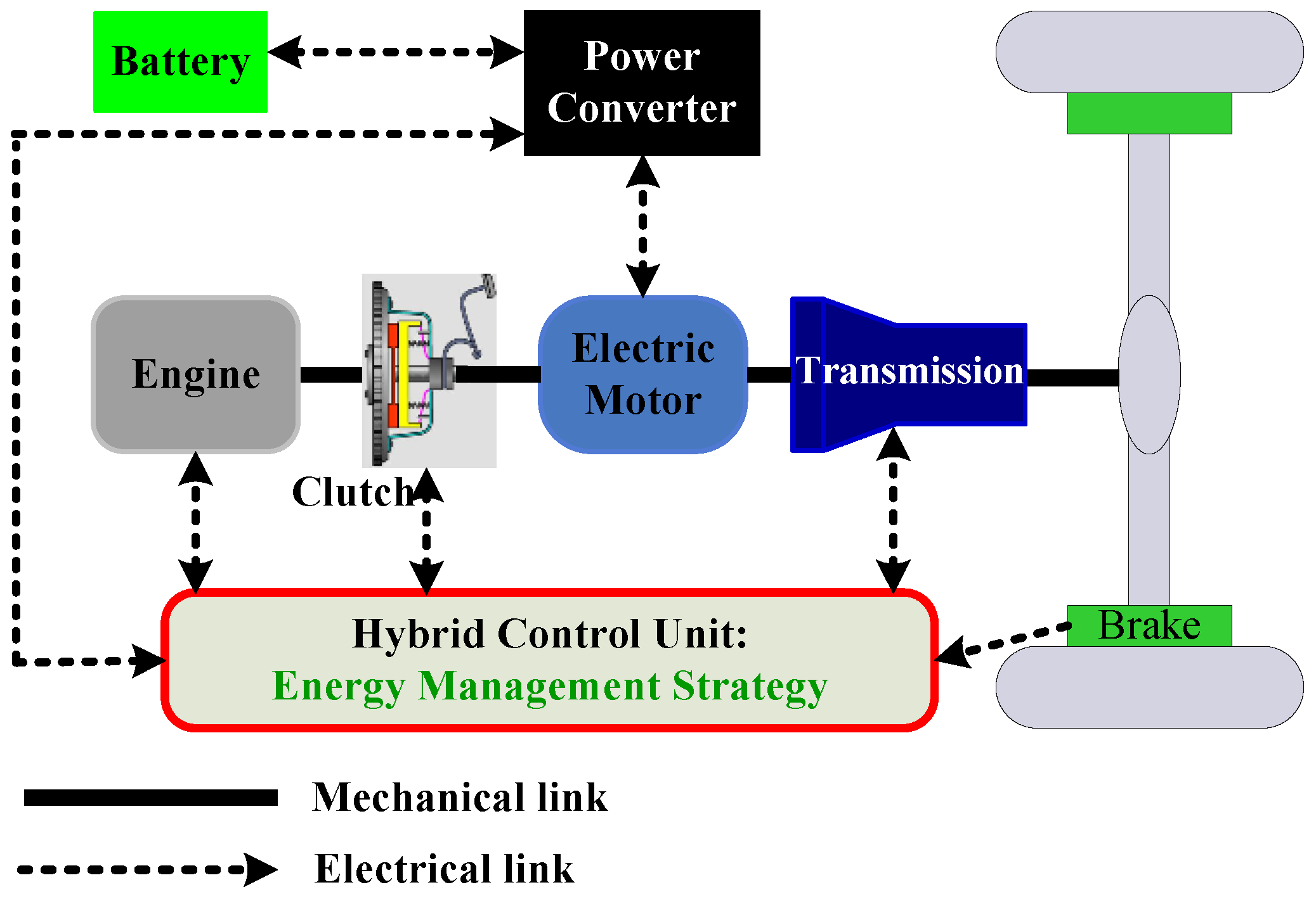
2.1. Parallel HEV System Configuration

In this paper, we studied a pre-transmission single-shaft torque-coupling parallel HEV as shown in Figure 1. The engine, the electric motor, the Nickel Metal Hydride (Ni-MH) battery pack, the automatic clutch, and the automated transmission constitute the parallel hybrid electric powertrain. The auto-clutch output is connected to the transmission input through an electric motor. The distinguished advantage of this architecture is an efficient motor assist operation. When the automatic clutch is disengaged, the engine will be off and isolated from the transmission. The motor will then drive the vehicle to obtain pure electrical propulsion. When the automatic clutch is engaged, the engine and the motor rotate at the same speed. Furthermore, during deceleration or on a down slope driving, the motor will work as a generator and the regenerative braking power, coming from the vehicle kinetic or potential energy, will be charged to the battery pack at the same time. The main vehicle information is shown in Table 1.

2.2. System Equations

The drive train components of the parallel HEV are all modeled according to the quasi-static principle. In other words, when the vehicle response frequency is obviously higher than that of the vehicle energy flow, this response will be ignored.
Vehicle Dynamics: The torque required by the driver in wheels Tw is determined by the following equation:
T w ( k ) = { η R ( g ( k ) ) ( T e ( k ) + T m ( k ) ) , T w ( k ) 0 R ( g ( k ) ) ( T e ( k ) + T m ( k ) ) η , T w ( k ) < 0
where η is the total transmission efficiency from the transmission to the driving wheels; R(g(k)) stands for the total transmission ratio when gear is g(k); Te and Tm represent the engine torque and motor torque respectively.
The angular speed of driving wheels ωw can be obtained from Kinematic equation as follows:
ω w ( k ) = v ( k ) / r w ( v ( k ) ) = ω m ( k ) / R ( g ( k ) )
where v(k) is the vehicle speed; rw(v(k)) is the dynamic radius of the wheel; ωm is the angular speed of the motor.
From the operating equation of this parallel HEV, the follow equation can be concluded.
ω w ( k + 1 ) = ω w ( k ) + T d e m ( k ) B w ω w ( k ) r w ( F r + F a ) M r r w 2
where Bw is the viscosity coefficient; Fr is the rolling resistance; Fa is the aerodynamic resistance; Mr = m + mr is the effective mass of the vehicle; m is the equipment mass; mr is the effective translation mass of the rotating components of the vehicle.
Engine: In this paper, we adopt the quasi-static principle and ignore the engine dynamic responses. In another word, we do not consider the engine temperature-varation effects and assume the engine has been fully warmed up. The fuel consumption rate and all emissions are assumed to be static functions of engine speed and engine torque, which can be obtained through looking up the engine map.
Transmission: The gearshift sequence of the automatic transmission is modeled as a discrete-time dynamic system.
g ( k + 1 ) = { 5 ,     g ( k ) + s h i f t ( k ) > 5 1 ,     g ( k ) + s h i f t ( k ) < 1 g ( k ) + s h i f t ( k ) , 1 g ( k ) + s h i f t ( k ) 5
where, g(k) is the current gear position number; shift(k) stands for the gear shift command. The value of shift(k) is constrained to 1, 0, and −1, respectively representing the gearshift command: downshift, sustain, and up-shift.
Motor: According to experimental data, motor efficiency is modeled as a function of the motor torque and the motor speed.
Battery: We ignore thermal-temperature effect and transient influence (due to internal capacitance) on the battery. The battery is modeled as a voltage source with an open circuit voltage Voc and an inner resistance Rint both relying on the battery state of charge SOC(k).
S O C ( k + 1 ) = S O C ( k ) V o c V o c 2 4 ( R i n t + R t ) T m ( k ) ω m ( k ) η m sgn ( T m ( k ) ) 2 ( R i n t + R t ) Q max
where Qmax is the maximum charge capacity of the battery; Rt is the terminal resistance of the battery; ηm is the motor efficiency.
As a result, we can conclude that the state vector of the parallel HEV includes four state variables: desired torque from the driver Tdem(k) = Te + Tm, angular speed of the driving wheels ωw, gear-position g(k), and battery state of charge SOC(k); the control vector of the parallel HEV system is comprised of the engine torque Te(k) and gear shift command shift(k).

2.3. Optimal Control Problem Formulation

The parallel HEV we studied in this paper is modeled as a discrete-time dynamic system. The evolution of the system state is described by the following equation:
x ( k + 1 ) = f ( x ( k ) , u ( k ) )
where u(k) is the control vector at time step k; x(k) is the state vector at time step k. From the analysis in part 2.2, we conclude the following equation:
{ x ( k ) = ( T d e m ( k ) , ω w ( k ) , g ( k ) , S O C ( k ) ) T u ( k ) = ( T e ( k ) , s h i f t ( k ) ) T
The parallel HEV operates according to the laws of Formulas (1)–(5).
To ensure the engine and battery safety, and the smooth operation of the motor, the following constraints are imposed in the optimization of the system:
{ ω e _ min ω e ( k ) ω e _ max S O C min S O C ( k ) S O C max T e _ min ( ω e ( k ) ) T e ( k ) T e _ max ( ω e ( k ) ) T m _ min ( ω m ( k ) , S O C ( k ) ) T m ( k ) T m _ max ( ω m ( k ) , S O C ( k ) )
We defined the EMS as a policy π according to which each state x will be mapped to a related action a. The state of parallel HEV will change from x to x' under action a. The goal of EMS is to find the control input u(k) to minimize the fuel consumption while satisfying the constraints in Equation (8). We adopt a value function J, which is defined as the expected cost-accumulation from state x to state x' in the future, to evaluate the policy π. In another word, the optimal EMS is the optimal policy π*, which has the minimum value function J*. Because the operating equations and the cost function of the parallel HEV system are both time-invariant and we do not have a final time of a driving cycle, the EMS problem is formulated as a dynamic optimization problem in an infinite horizon shown in Equation (9). The benefits of the infinite horizon problem are that the generated control policy is time-invariant and thus could be easily implemented.
J * = min lim N E { k = 0 N 1 γ k L ( x ( k ) , u ( k ) ) }
where N is the sampling number in a driving cycle; γ is the discount factor, which ensures the minimum value function convergence; L(x(k),u(k)) represents the cost function defined specifically as follows:
L ( x ( k ) , u ( k ) ) = L f u e l ( k ) + α L e m s ( k ) + λ L S O C ( k ) + υ L g s ( k )
where Lfuel, Lems, Lsoc, and Lgs are respectively the cost of the fuel consumption, emission, battery’s state of charge, and gear shift; α, λ and υ stand for the weight factor of the emission, battery SOC, and the gear shift in the cost function respectively. They represent the importance of related item in L(x(k),u(k)).
Lsoc is defined as Equation (11) to keep charge sustenance and to minimize the probability of battery depletion.
L S O C = ( S O C ( k ) S O C r e f ) 2
where, SOCref is the desired battery state of charge at the end of the driving cycle.
The gear-shifting schedule is crucial to the vehicle fuel economy. Meanwhile, frequent gear-shifting will influence the comfort and drivability. As a result, Lgs is defined as follows:
L g s = | s h i f t ( k ) |

3. Problem Implementation

We firstly use DP to get a max performance benchmark, even though it will not work in practice. Then we develop the SDP approach to solve the EMS problem.

3.1. Dynamic Programming (DP) Method

The DP technique is based on the optimality principle and guarantees the global optimal. Bellman contributed a lot to the application of the priciple [43]. The details of this principle is as follows [44]:
Let π * = { u 0 * , u 1 * , , u N 1 * } be an optimal policy for the basic problem, and then we assume that when using π * , a given state x i occurs at time step i with positive probability. Consider the subproblem whereby we are at x i at time step i and wish to minimize the “cost-to-go” from time step i to time step N, E { g N ( x N ) + k = i N 1 g k ( x k , u k ( x k ) , w k ) } . Then the truncated policy { u i * , u i + 1 * , , u N 1 * } is optimal for this subproblem.
Then in the EMS problem, for the driving cycle is known in advance, the DP approach is the deterministic DP method. The overall optimization problem can be decomposed into a sequence of simpler minimization sub-problems as follows.
Time step N − 1:
J N 1 * ( x ( N 1 ) ) = min u ( N 1 ) L ( x ( N 1 ) , u ( N 1 ) )
Time step k , k [ 0 k < N 1 ) :
J k ( x ( k ) ) = min u ( k ) [ L ( x ( k ) , u ( k ) ) + J k + 1 ( x ( k + 1 ) ) ]
where J k ( x ( k ) ) is the optimal value function at time step k under state x(k). The backward method can be used to solve Equations (13) and (14). The optimal control vector at time step k will be as follows:
u * ( k ) = arg min u ( k ) J k ( x ( k ) )
The optimal control law will be:
π * = { u * ( 1 ) , u * ( 2 ) , , u * ( N 1 ) }
The main disadvantage of the DP approach, compared with other methods, is still the heavy computation burden, which limits the DP method application in EMS.

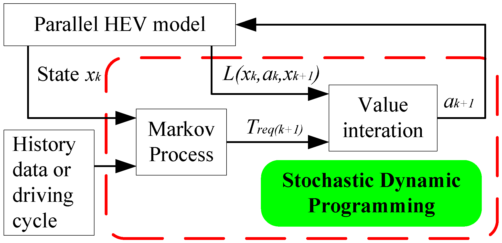
3.2. EMS Based on Stochastic Dynamic Programming (SDP) Approach

3.2.1. SDP Method Description

SDP is widely used in the optimization problems of uncertain planning. The essence of the SDP problem is to reach the termination state with minimum expected cost, where the termination occurs with probability 1. The DP method is a special case of SDP, where the transition probability is equal to 1 for each state-control pair [44]. According to this, generally speaking, the SDP approach significantly reduces the computation burden compared with the DP method.
We define SDP problem as M = (X, A, T, L), where X, A, T, and L stand for finite state space, finite action space, probability transition matrix, and cost function respectively. At each step, the system is in one state of X = {x1, x2,, xN}. In each state xkX, k = 1, 2, …, N − 1, there is a finite set of actions A = {a1, a2, …, aM} that the system performs. The parallel HEV system operates according to P(xk, ak, xk+1), the transitioning probability from state xk to state xk+1 under action ak, k = 1, 2, …, M, performed. T is composed of all the P(xk, ak, xk+1). The performance evaluation is given by the cost function L(xk, ak, xk+1) which is the cost that the vehicle has to pay for state transition from xk to xk+1 under action ak. A policy π is defined as a sequence of state-to-action maps specifying which action is chosen from the current state to the next state visited at each transition time.
A value function U(xk) is defined as the sum of future costs for state xk under a policy π. The optimal value function U*(xk) is defined as the average of all the minimum costs function of each state. The optimal value function U*(xk) is then obtained by solving the following equation after k0 time steps:
U * ( x k 0 ) = min π E { k = k 0 γ k k 0 L ( x k , π ( x k ) , x k + 1 ) }
where γ ∈ (0, 1) is the discount factor, which assures the infinite sum of rewards convergence. The closer γ is chosen to 1, the more long-term the system performance expectations are taken into account.
The Bellman Formula shows the relationship between the value function of each state and that of its neighbors:
U * ( x k ) = min a k x k + 1 P ( x k , a k , x k + 1 ) ( L ( x k , a k , x k + 1 ) + γ U * ( x k + 1 ) )
The agent selects optimal action sequences according to the following equation.
π * ( x k ) = arg min a k x k + 1 P ( x k , a k , x k + 1 ) ( L ( x k , a k , x k + 1 ) + U * ( x k + 1 ) )

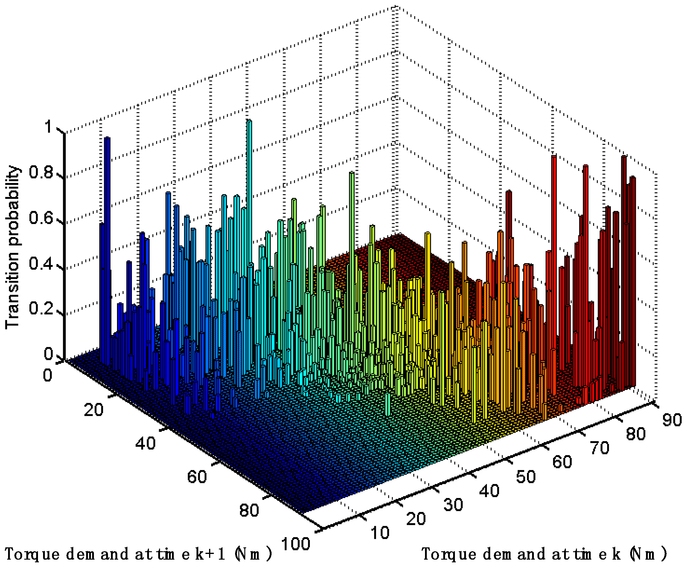
3.2.2. Stochastic Modeling of the Driver Torque Demand

Markov processes are applicable in fields characterized by uncertain state transitions and a necessity for making sequential decisions [28]. Markov processes satisfy the Markov property, which means that state transitions are independent from actions and states encountered before the current decision step.
The required torque from driver is another expressing of the demanded power. When operating a vehicle, a driver generates the acceleration and braking signals based on personal desire and interference from driving conditions (e.g., congestion and stops) which leads to the uncertain characteristics of driver demanding torque. In another word, Tdem at the next time step is only related with that of the current time step. We can conclude Tdem meets Markov property. Therefore, it is modeled as a Markov process in this paper.
Meanwhile, Tdem at each time step could be calculated according to the inverse kinematics model of the parallel HEV with the help of the history data of driver operations or government driving cycle. After that, Tdem is discretized to a finite set with NT values, T d e m { T d e m 1 , T d e m 2 , , T d e m N T } . We can then adopt the Maximum Likelihood Estimation (MLE) to calculate the probability transition matrix T = ( T i j ) m × n , where m and n represent the number of rows and columns of the matrix respectively; Tij stands for the one step transition probability on the condition of T d e m = T d e m i at time step k and T d e m = T d e m j at time step k+1.
T i , j = Pr { T d e m j | T d e m = T d e m i } i , j = 1 , 2 , , N T
where j = 1 N T T i , j = 1 .
As an example, the transition probability of an American standard driving cycle, Urban Dynamometer Driving Schedule (UDDS), is shown in Figure 2.

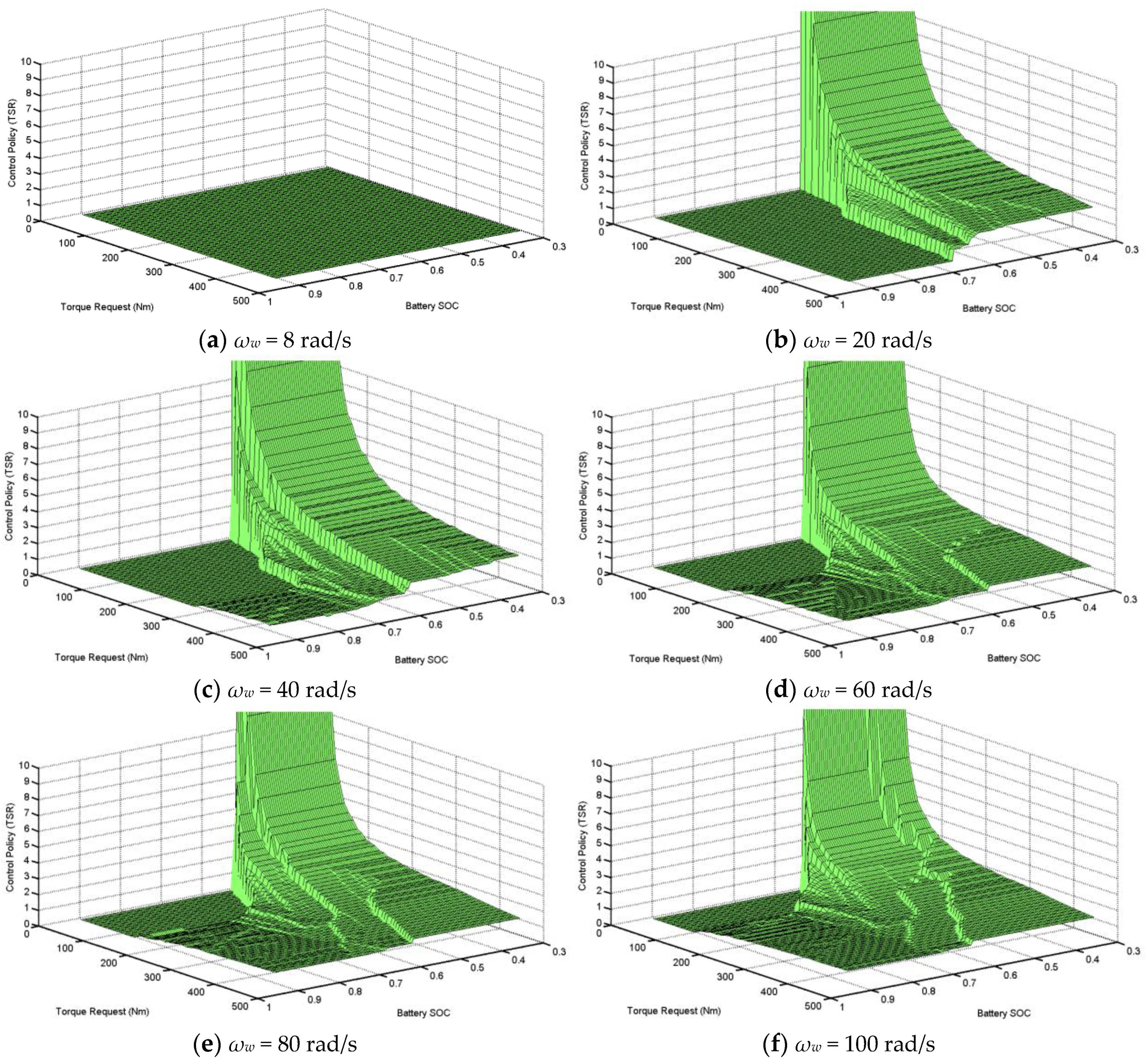
3.2.3. Implementation of the EMS Based on the SDP Approach

When implementing the SDP EMS, we firstly discretized the vehicle continuous state variables (e.g., angular speed of driving wheels ωw, state of charge of the battery pack SOC and the output torque of engine Te) to one finite grid respectively. The summary of the parallel HEV modeling parameters is shown in Table 2. Secondly, according to previous driving records, the Maximum Likelihood Estimation (MLE) method was adopted to acquire the probability transition matrix of required torque from the driver. Thirdly, the policy iteration method was utilized to calculate the optimal cost function. The maximum iteration number in this paper is about 70 times. The policy iteration alternatively performs a policy evaluation step and a policy improvement step until the optimal cost function converges. The policy evaluation calculates the value function when time step k (k =1, 2, …, N), U k = U π k , given policy πk. In the policy improvement step, according to the value function calculated at time step k, a greedy algorithm was performed to get a new policy πk+1. The overall schematic diagram of the SDP approach is shown in Figure 3.
Although the SDP approach has less time steps than the DP approach, SDP has more computation to do the probabilities for each state and policy iteration step, whereas DP is a single iteration. In this research, we adopted the following approaches to accelerate the optimization search of the SDP approach. Firstly, the cost matrix of one step state-action pairs stored in memory in the form of (x(k), a(k), x(k + 1), Lfuel, Lems, Lsoc, Lgs) for computing quickly. Secondly, we used vector operations in MATLAB7.14 to efficiently select parameters for cost function. The computation time was significantly reduced by similar engineering knowledge, e.g., the SDP toolbox in MATALAB. Thirdly, the SDP strategy took the form of a table that maps current state of parallel HEV to an optimal action. This table could be synthesized to a function to realize in the embedded system.
In the SDP algorithm, a balance between the discretization dimension and the computational complexity exists all the time. A coarse discretization will result states and actions not smooth and poor algorithm performance; more discretization points will lead to a large state-action pair number, which results in a long computing time. We firstly used a coarse discretization to compute the corresponding cost function matrix. A linear interpolation was then adopted to produce a better cost function matrix.

4. Performance Evaluation

Simulation experiments were done with ADVISOR2002 (NREL’s Advanced Vehicles Simulator) on a Pentium IV computer with Intel Core 2 Duo 3.0 GHZ CPU and 2G memory to evaluate performance of the SDP approach with a time consumption of 180 senconds. ADVISOR is a set of models, data, and script text files for use with MATLAB and Simulink. The modeling parameters of the parallel HEV are shown in Table 2. We defined a torque-split-ratio TSR = Te/Tdem to quantify the positive power flows in the powertrain and to analyze the EMS performance. Four operation modes were also defined when the required torque is in the positive manner: pure electric traction mode (TSR = 0), hybrid traction mode (0 < TSR < 1), pure engine traction mode (TSR = 1) and battery charging mode (TSR > 1).

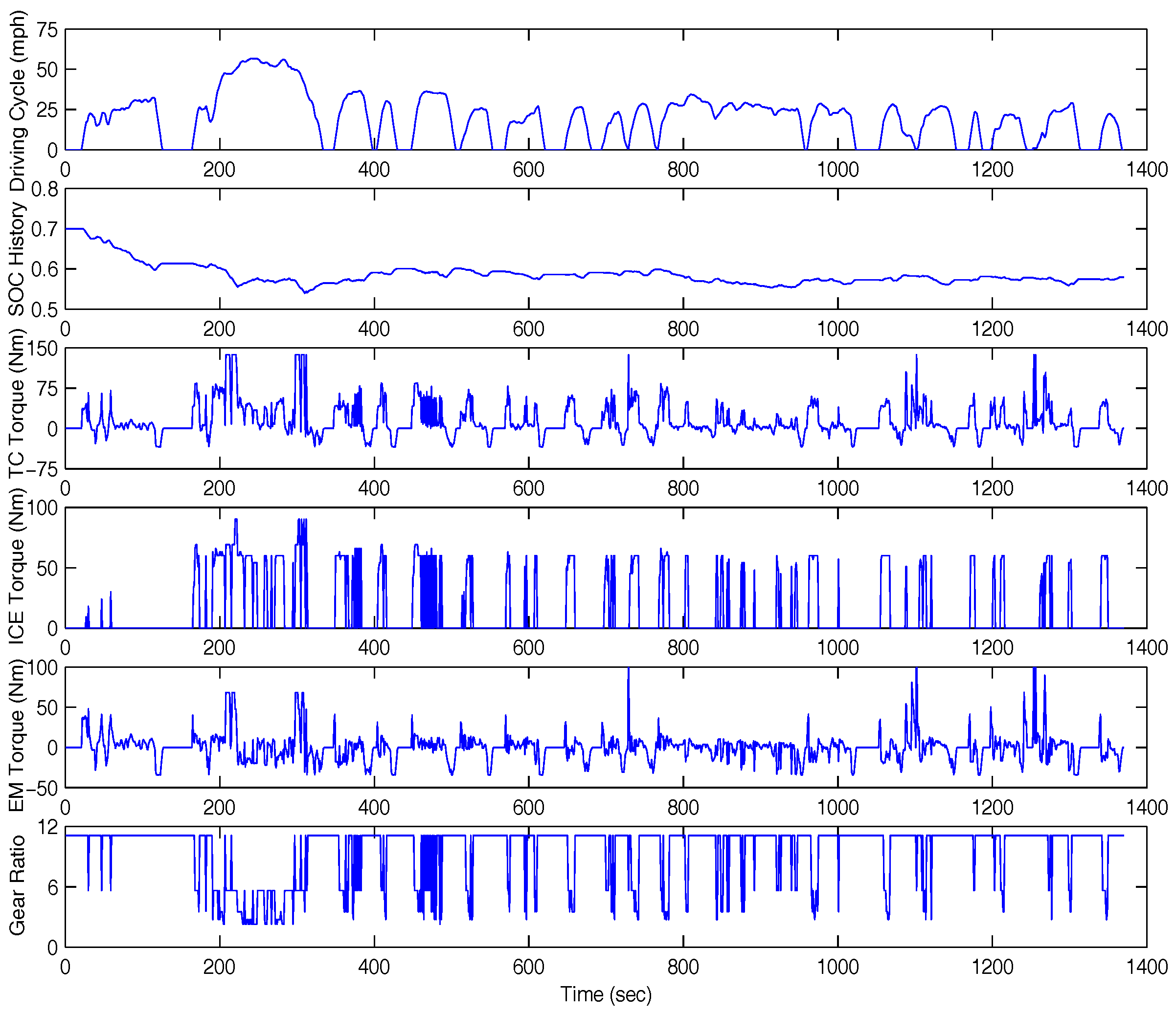
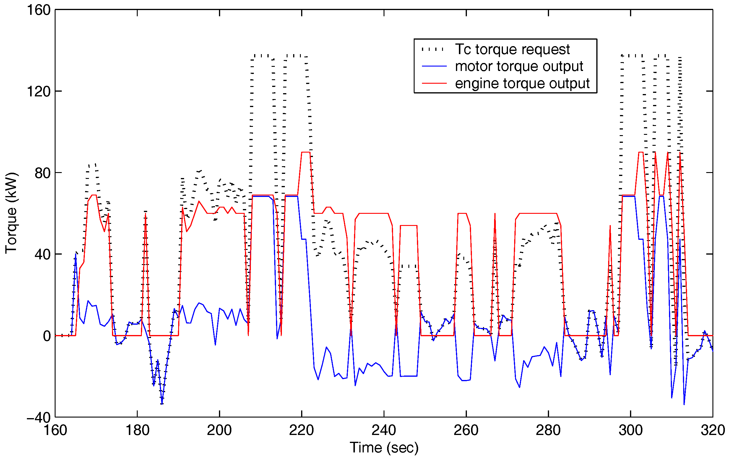
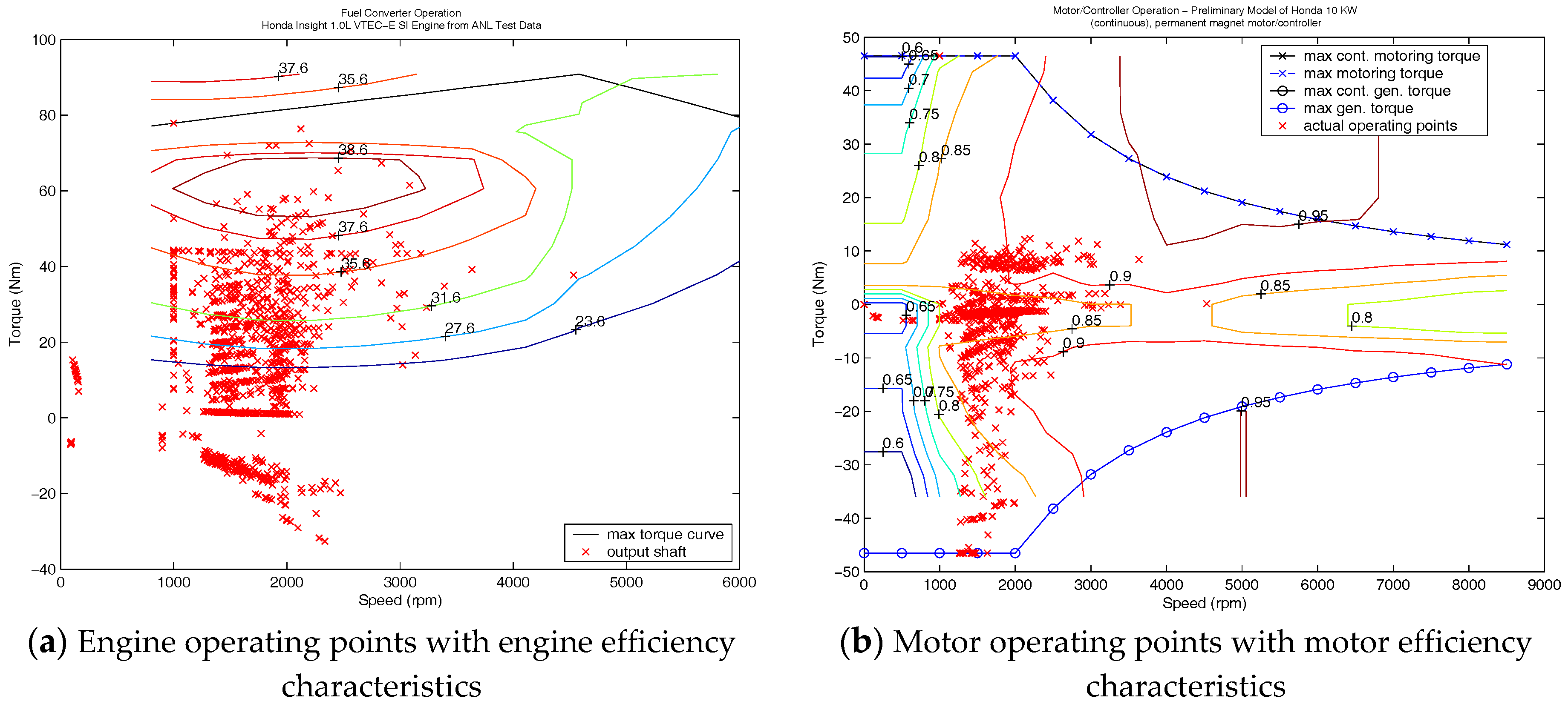
4.1. Simulation Results under the Urban Dynamometer Driving Schedule (UDDS)

We firstly did simulations under the standard driving cycle UDDS (Urban Dynamometer Driving Schedule) to test the SDP EMS performances.
The TSR maps of SDP EMS at driving wheel angular speed of 8 rad/s, 20 rad/s, 40 rad/s, 60 rad/s, 80 rad/s, and 100 rad/s, are shown in Figure 4a–f respectively. From Figure 4, we can see that when SOC > 0.7 and Tdem < 180 N·m, a relative small torque required, TSR = 0 and the vehicle is in a low speed. Thus, the drive train is in the electric-alone traction mode; when SOC > 0.7 and Tdem ≥ 180 N·m, 0 < TSR < 1 and the vehicle is in the hybrid traction mode; when 0.5 ≤ SOC ≤ 0.7, the SOC has reached its bottom line and the drive train is in engine-alone traction mode; when SOC < 0.5, the constraint on SOC is not met, TSR > 1 and the engine will charge the battery no matter what vechile speed (from 20 rad/s to 100 rad/s). We can also see that from Figure 4b–f), when the same Tdem, no matter vehicle speed variation, TSR will increase with the SOC decreasing. In another word, given a specific Tdem, power though the engine and fuel consumption will increase with the decreasing of SOC to meet the battery constraints. When Tdem < 0, EMS could be handled with a simple way: the motor will be in regenerative braking mode and recover as much regeneration energy as possible within constraints imposed by the motor and the battery. The mechanical brake device will supply whatever is left over.
The SDP EMS simulation results with time going on are shown in Figure 5. We can see from Figure 5 that SDP EMS tends to keep SOC within the range of 50%–65%, which guarantees efficient battery operation and prevents battery depletion. We can also see the range of SOC leaves enough capacity to handle an extended period of the battery discharge and enough capacity to absorb a long period of charging. That means the battery is maintained near a balance point to ensure charge-sustaining. The simulation results show the reliability and viability of SDP EMS.
Figure 6 shows the torque distribution trajectories from 160–300 s, which further explains the benefits of SDP EMS in improving fuel economy. It could be seen that the engine provides the cruising torque demand while the battery pack through motor helps meet the peak torque demand. The output torque profile of an engine, between 40 N∙m and 60 N∙m, has a large constant region but little peaking, which satisfies the quasi-static model of the engine.
Figure 7a,b respectively depict the torque-speed operating points of engine and motor using the rule-based EMS under UDDS. Figure 8a,b report those using the SDP EMS. Figure 7 and Figure 8 show that the engine operating points of SDP distribute in the higher efficiency region than that of the rule-based method. Hence, fuel consumption of SDP will be lower than that of the rule-based method. The SDP approach helps improving fuel economy and alleviating the emissions. We could see from Figure 8a that most of the engine operating points are in 35.6%–38%, and the engine torque is in the domain of 40 N∙m and 60 N∙m. When higher torque is needed, the engine of SDP will give a good performance. In the rule-based EMS, the motor operating points are mainly concentrated in low efficiency region; in the SDP strategy, the motor operating points are located more in high efficiency operation region, which shows that the SDP method enjoys higher motor performance than the rule-based EMS.

4.2. Comparisons of Simulation Results under Different Driving Cycles

To test the robustness of the SDP controller, two driving cycles—1015 and a new one—were also engaged in simulations. The new driving cycle, defined by ourselves, consisted of some repetitions of three urban schedules of different natures (e.g., UDDS + 1015 + WVUCITY). The 1015 driving cycle used here is the one in ADVISOR2002, depicting the Japanese 1015 mode driving cycle, which represents an urban cycle with road of zero or near zero grades [45]. Meanwhile, in the new driving cycle simulation, the transition probability matrix was built for each driving cycle individually.
Moreover, a rule-based approach, the Parallel Electric Assist Control Strategy (PEACS), and DP approach simulations were also conducted and compared with the SDP simulation to evaluate the SDP performance though four aspects: fuel economy, engine efficiency, motor efficiency, and generating efficiency. The PEACS is a heuristic strategy defined in the ADVISOR document with five different operating modes. When vehicle speed below the minimum speed is set in advance, the motor propels the vehicle alone. When the demand torque is bigger than the maximum output torque of the engine, the motor provides an auxiliary torque. In the regenerative braking mode, the braking torque drives the motor for battery charging. Given the rotate speed and demand torque, an engine with low efficiency will be off and the motor will drive the vehicle alone. With a low SOC, the engine will drive the motor for battery charging. The cost function expressions and parameter-selection in PEACS and the DP approach are the same with the SDP strategy discussed above.
Simulation results from UDDS, 1015 and the composite driving cycle are reported in Table 3, Table 4 and Table 5. We could conclude that the SDP strategy achieves obviously better results in both fuel consumption and components efficiency (e.g., engine efficiency, motoring efficiency, and generating efficiency) compared with the rule-based control strategy, PEACS. Simulation results of SDP and the global optimum results using DP show little difference within a few percent.

5. Conclusions

EMS design of HEVs is a challenging problem due to its complex structure and uncertain driving conditions. A stochastic dynamic program (SDP) is adopted to solve the EMS problem of a pre-transmission single-shaft torque-coupling parallel HEV. The special configuration enjoys an effective motor assist operation. In SDP, the required torque from the driver is modeled as a one-state Markov process to represent the uncertainty of future driving situations. ADVISOR2002 simulation results under three different driving cycles: UDDS, 1015, and a self-defining one (UDDS + 1015 + WVUCITY), indicate that this special SDP EMS achieves little performance than DP method. The engine efficiency and motor efficiency are greatly improved compared with a traditional rule-based strategy, PEACS. Therefore, we can conclude that the SDP approach has the potential for an off-line real-time on board control application to use the host computer-lower machine structure. The host computer is responsible for the establishment of the transfer probability matrix and the problem solution. Moreover, the slave computer, or the embedded system, is responsible for data collection and regular updating of the energy management strategy.
The SDP in this paper is a near-optimal control strategy only considering the fuel economy, gear-shift, and SOC sustaining. Our future work will focus on the aspects that could be tradeoff with the fuel economy—e.g., PM emissions, engine noise characteristics, other battery safety indicators and so forth.

Acknowledgments

This work is supported by National Natural Science Foundation of China (grant number 61273139) and by National Natural Science Foundation of China (grant number 61603377).

Author Contributions

Feiyan Qin designed the SDP control strategy and wrote the whole manuscript. Weimin Li proposed the SDP control strategy and checked the whole manuscript. Guoqing Xu, Yue Hu, and Kun Xu checked the manuscript.

Conflicts of Interest

The authors declare no conflict of interest.

References

  1. Andreas, A.M. Supervisory power management control algorithms for hybrid electric vehicles: A survey. IEEE Trans. Intell. Transp. Syst. 2014, 15, 1869–1885. [Google Scholar]
  2. Zhang, P.; Yan, F.W.; Du, C.Q. A comprehensive analysis of energy management strategies for hybrid electric vehicles based on bibliometrics. Renew. Sustain. Energy Rev. 2015, 48, 88–104. [Google Scholar] [CrossRef]
  3. Jalil, N.; Kheir, A.N.; Salman, M. A rule-based energy management strategy for a series hybrid vehicle. In Proceedings of the 1997 American Control Conference, Albuqueque, NM, USA, 4–6 June 1997; IEEE: New York, NY, USA, 1997; pp. 689–693. [Google Scholar]
  4. Fernandes Trovão, J.P.; Gameiro Pereirinha, P.J. Control scheme for hybridized electric vehicles with an online power follower management strategy. IET Electr. Syst. Transp. 2015, 5, 12–23. [Google Scholar] [CrossRef]
  5. Park, J.; Oh, J.; Park, Y.; Lee, K. Optimal power distribution strategy for series-parallel hybrid electric vehicles. In Proceedings of the 1st International Forum on Strategic Technology, Ulsan, Korea, 18–20 October 2006; IEEE: New York, NY, USA, 2007; pp. 37–42. [Google Scholar]
  6. Zhou, W.H.; Li, M.; Yin, H.; Ma, C.B. An adaptive fuzzy logic based energy management strategy for electric vehicles. In Proceedings of the IEEE 23rd International Symposium on Industrial Electronics, Istanbul, Turkey, 1–4 June 2014; IEEE: New York, NY, USA, 2016; pp. 1778–1783. [Google Scholar]
  7. Schouten, N.J.; Salman, M.A.; Kheir, N.A. Fuzzy Logic Control for Parallel Hybrid Vehicles. IEEE Trans. Control Syst. Technol. 2002, 10, 460–468. [Google Scholar] [CrossRef]
  8. Hu, Y.; Li, W.M.; Hui Xu, H.; Xu, G.Q. An online learning control strategy for hybrid electric vehicle based on fuzzy Q-learning. Energies 2015, 8, 11167–11186. [Google Scholar] [CrossRef]
  9. Won, J.S.; Langari, R. Intelligent energy management agent for a parallel hybrid vehicle-Part II: Torque distribution, charge sustenance strategies, and performance results. IEEE Trans. Veh. Technol. 2005, 54, 935–953. [Google Scholar] [CrossRef]
  10. Odeim, F.; Roes, J.; Wülbeck, L.; Heinzel, A. Power management optimization of fuel cell/battery hybrid vehicles with experimental validation. J. Power Sources 2014, 252, 333–343. [Google Scholar] [CrossRef]
  11. Hung, Y.H.; Tung, Y.M.; Chang, C.H. Optimal control of integrated energy management/mode switch timing in a three-power-source hybrid powertrain. Appl. Energy 2016, 173, 184–196. [Google Scholar] [CrossRef]
  12. Cui, N.X.; Lian, F.X.; Wu, J.; Wang, X.X. Optimization of HEV energy management strategy based on driving cycle modeling. In Proceedings of the 34th Chinese Control Conference, Hangzhou, China, 28–30 July 2015; IEEE: New York, NY, USA, 2015; pp. 7983–7987. [Google Scholar]
  13. Zou, Y.; Liu, T.; Liu, D.X.; Sun, F.C. Reinforcement learning-based real-time energy management for a hybrid tracked vehicle. Appl. Energy 2016, 171, 372–382. [Google Scholar] [CrossRef]
  14. Qi, Y.L.; Wang, W.D.; Xiang, C.L. Neural network and efficiency-based control for dual-mode hybrid electric vehicles. In Proceedings of the 34th Chinese Control Conference, Hangzhou, China, 28–30 July 2015; IEEE: New York, NY, USA, 2015; pp. 8103–8108. [Google Scholar]
  15. Khayyam, H.; Bab-Hadiashar, A. Adaptive intelligent energy management system of plug-in hybrid electric vehicle. Energy 2014, 69, 319–335. [Google Scholar] [CrossRef]
  16. Kim, N.; Cha, S.; Peng, H. Optimal control of hybrid electric vehicles based on Pontryagin’s Minimum Principle. IEEE Trans. Control Syst. Technol. 2011, 19, 1279–1287. [Google Scholar]
  17. Ansarey, M.; Panahi, M.S.; Ziarati, H.; Mahjoob, M. Optimal energy management in a dual-storage fuel-cell hybrid vehicle using multi-dimensional dynamic programming. J. Power Sources 2014, 250, 359–371. [Google Scholar] [CrossRef]
  18. Peng, J.K.; He, H.W.; Xiong, R. Rule based energy management strategy for a series–parallel plug-in hybrid electric bus optimized by dynamic programming. Appl. Energy 2016, 185, 1633–1643. [Google Scholar] [CrossRef]
  19. Lin, C.C.; Peng, H.; Grizzle, J.W.; Kang, J.M. Power management strategy for a parallel hybrid electric truck. IEEE Trans. Control Syst. Technol. 2003, 11, 839–849. [Google Scholar]
  20. Opila, D.F.; Wang, X.Y.; McGee, R.; Gillespie, R.B.; Cook, J.A.; Grizzle, J.W. An energy management controller to optimally trade off fuel economy and drivability for hybrid vehicles. IEEE Trans. Control Syst. Technol. 2012, 20, 1490–1505. [Google Scholar] [CrossRef]
  21. Finesso, R.; Spessa, E.; Venditti, M. Cost-optimized design of a dual-mode diesel parallel hybrid electric vehicle for several driving missions and market scenarios. Appl. Energy 2016, 177, 366–383. [Google Scholar] [CrossRef]
  22. Stockar, S.; Marano, V.; Canova, M.; Rizzoni, G.; Guzzella, L. Energy-optimal control of plug-in hybrid electric vehicles for real-world driving cycles. IEEE Trans. Veh. Technol. 2011, 60, 2949–2962. [Google Scholar] [CrossRef]
  23. Zheng, C.H.; Xu, G.Q.; Xu, K.; Pan, Z.M.; Liang, Q. An energy management approach of hybrid vehicles using traffic preview information for energy saving. Energy Convers. Manag. 2015, 105, 462–470. [Google Scholar] [CrossRef]
  24. Sun, C.; Hu, X.S.; Moura, S.J.; Sun, F.C. Velocity predictors for predictive energy management in hybrid electric vehicles. IEEE Trans. Control Syst. Technol. 2015, 23, 1197–1204. [Google Scholar]
  25. Meyer, R.T.; DeCarlo, R.A.; Jali, N.M.; Ariyur, K.B. Behavioral modeling and optimal control of a vehicle mechanical drive system. In Proceedings of the 2015 American Control Conference, Chicago, IL, USA, 1–3 July 2015; IEEE: New York, NY, USA, 2015; pp. 2266–2271. [Google Scholar]
  26. Li, L.; You, S.X.; Yang, C.; Yan, B.J.; Song, J.; Chen, Z. Driving-behavior-aware stochastic model predictive control for plug-in hybrid electric buses. Appl. Energy 2016, 162, 868–879. [Google Scholar] [CrossRef]
  27. Zeng, X.R.; Wang, J.M. A parallel hybrid electric vehicle energy management strategy using stochastic model predictive control with road grade preview. IEEE Trans. Control Syst. Technol. 2015, 23, 2416–2423. [Google Scholar] [CrossRef]
  28. Negenborn, R.R.; Schutter, B.D.; Wiering, M.A.; Hellendoorn, H. Learning-based model predictive control for Markov decision processes. In Proceedings of the 16th Triennial World Congress, Prague, Czech Republic, 4–8 July 2005; IFAC: New York, NY, USA, 2005; pp. 354–359. [Google Scholar]
  29. Schori, M.; Boehme, T.J.; Jeinsch, T.; Schultalbers, M. A robust predictive energy management for plug-in hybrid vehicles based on hybrid optimal control theory. In Proceedings of the 2015 American Control Conference, Chicago, IL, USA, 1–3 July 2015; IEEE: New York, NY, USA, 2015; pp. 2278–2284. [Google Scholar]
  30. Sun, C.; Sun, F.C.; Hu, X.S.; Hedrick, J.K.; Moura, S. Integrating traffic velocity data into predictive energy management of plug-in hybrid electric vehicles. In Proceedings of the 2015 American Control Conference, Chicago, IL, USA, 1–3 July 2015; IEEE: New York, NY, USA, 2015; pp. 2267–2272. [Google Scholar]
  31. Zeng, X.R.; Wang, J.M. Stochastic optimal control for hybrid electric vehicles running on fixed routes. In Proceedings of the 2015 American Control Conference, Chicago, IL, USA, 1–3 July 2015; IEEE: New York, NY, USA, 2015; pp. 3273–3278. [Google Scholar]
  32. Lin, C.C.; Peng, H.; Grizzle, J.W. A stochastic control strategy for hybrid electric vehicles. In Proceedings of the 2004 American Control Conference, Boston, MA, USA, 30 June–2 July 2004; IEEE: New York, NY, USA, 2005; pp. 4710–4715. [Google Scholar]
  33. Fletcher, T.; Thring, R.; Watkinson, M. An energy management strategy to concurrently optimize fuel consumption & PEM fuel cell lifetime in a hybrid vehicle. Int. J. Hydrog. Energy 2016, 41, 21503–21515. [Google Scholar]
  34. Li, L.; Yan, B.; Yang, C.; Zhang, Y.; Chen, Z.; Jiang, G. Application-oriented stochastic energy management for plug-in hybrid electric bus with AMT. IEEE Trans. Control Syst. Technol. 2016, 65, 4459–4470. [Google Scholar] [CrossRef]
  35. Vagg, C.; Akehurst, S.; Brace, C.J.; Ash, L. Stochastic dynamic programming in the real-world control of hybrid electric vehicles. IEEE Trans. Control Syst. Technol. 2016, 24, 853–866. [Google Scholar] [CrossRef]
  36. Du, Y.; Zhao, Y.; Wang, Q.; Zhang, Y.; Xia, H. Trip-oriented stochastic optimal energy management strategy for plug-in hybrid electric bus. Energy 2016, 115, 1259–1271. [Google Scholar] [CrossRef]
  37. Li, L.; Yan, B.; Song, J.; Zhang, Y.; Jiang, G.; Li, L. Two-step optimal energy management strategy for single-shaft series-parallel powertrain. Mechatronics 2016, 36, 147–158. [Google Scholar] [CrossRef]
  38. Opila, D.F.; Wang, X.; McGee, R.; Gillespie, R.B.; Cook, J.A.; Grizzle, J.W. Real-world robustness for hybrid vehicle optimal energy management strategies incorporating drivability metrics. J. Dyn. Syst. Meas. Control 2014, 136, 061011. [Google Scholar] [CrossRef]
  39. Moura, S.J.; Fathy, H.K.; Callaway, D.S.; Stein, J.L. A stochastic optimal control approach for power management in plug-in hybrid electric vehicles. IEEE Trans. Control Syst. Technol. 2011, 19, 545–555. [Google Scholar] [CrossRef]
  40. Zeng, X.; Wang, J. A two-level stochastic approach to optimize the energy management strategy for fixed-route hybrid electric vehicles. Mechatronics 2016, 38, 93–102. [Google Scholar] [CrossRef]
  41. Tate, E.D.; Grizzle, J.W.; Peng, H. Shortest path stochastic control for hybrid electric vehicles. Int. J. Robust Nonlinear Control 2008, 18, 1409–1429. [Google Scholar] [CrossRef]
  42. Tate, E.D.; Grizzle, J.W.; Peng, H. SP-SDP for fuel consumption and tailpipe emissions minimization in an EVT hybrid. IEEE Trans. Control Syst. Technol. 2010, 18, 673–687. [Google Scholar] [CrossRef]
  43. Bellman, R.E.; Dreyfus, S.E. Applied Dynamic Programming; Princeton University Press: Princeton, NJ, USA, 1962. [Google Scholar]
  44. Dimitri, P.B. Dynamic Programming and Optimal Control Volume I, 3rd ed.; Athena Scientific: Belmont, MA, USA, 1995; pp. 18–19, 404–410. [Google Scholar]
  45. National Renewable Energy Lab. Evaluation of Range Estimates for Toyota FCHV-Adv under Open Road Driving Conditions. Available online: http://www.nrel.gov/hydrogen/pdfs/toyota_fchv-adv_range_verification.pdf (accessed on 8 February 2017).
Figure 1. Configuration of the parallel HEV drive train.
Energies 10 00214 g001
Figure 2. Transition probability of Tdem for standard driving cycle UDDS.
Energies 10 00214 g002
Figure 3. Overall schematic diagram of the SDP approach.
Energies 10 00214 g003
Figure 4. The TSR maps for SDP EMS under UDDS at different driving wheel angular speed, ωw.
Energies 10 00214 g004
Figure 5. SDP EMS simulation results under UDDS.
Energies 10 00214 g005
Figure 6. Torque split trajectory using SDP EMS under UDDS.
Energies 10 00214 g006
Figure 7. Torque-speed operating points of engine and motor using the PEACS EMS.
Energies 10 00214 g007
Figure 8. Torque-speed operating points of engine and motor using the SDP EMS.
Energies 10 00214 g008
Table 1. Important parameters of the parallel HEV.
ItemParameterValue
Spark ignition (SI) engineDisplacement (L)1.0
Maximum power (kW at 5700 r/min)50
Maximum torque (N∙m at 5600 r/min)89.5
Permanent magnet motorMaximum power (kW)10
Maximum torque (N∙m)46.5
Peak efficiency (%)0.96
Advanced Ni-MH batteryCapacity (Ah)6
Nominal cell voltage (V)1.2
Total cells120
Automated transmissionSpeed5
Gear ratio2.2791/2.7606/3.5310/5.6175/11.1066
VehicleCurb weight (kg)1000
Table 2. Summary of the modeling parameters for parallel HEV.
ParameterValue
Sampling time (s)1
Discretization-resolution of SOC0.005
Discretization-resolution of ωw2
Discretization-resolution of g(k)1
Discretization-resolution of Tdem10
Discretization-resolution of Te (N∙m)1
Discretization-resolution of shift(k)1
Weight factor in the cost function α0
Weight factor in the cost function λ1000
Weight factor in the cost function υ0.5
SOC00.7
SOCref0.7
Maximum interation number70
Table 3. Simulation results for CYC_UDDS.
EMSPEACSDPSDP
Fuel economy (mpg)53.971.768.3
Engine efficiency (%)24.637.435.7
Motoring efficiency (%)87.294.791.1
Generating efficiency (%)79.995.893.4
Table 4. Simulation results for CYC_1015.
EMSPEACSDPSDP
Fuel economy (mpg)52.260.758.2
Engine efficiency (%)23.438.236.1
Motoring efficiency (%)81.390.387.0
Generating efficiency (%)83.891.790.5
Table 5. Simulation results for 1015 + UDDS + WVUCITY.
EMSPEACSDPSDP
Fuel economy (mpg)56.366.562.1
Engine efficiency (%)24.838.136.3
Motoring efficiency (%)84.289.786.1
Generating efficiency (%)79.696.191.8

