Article

Computational Study of the Noise Radiation in a Centrifugal Pump When Flow Rate Changes

1
School of Energy and Power Engineering, Shandong University, Jinan 250061, China
2
School of Mechanical and Mining Engineering, University of Queensland, Brisbane 4067, Australia
3
Thermal Management Research Group, Efficient Energy Transfer (ηET) Department, Bell Labs Ireland, Nokia, Dublin D15 Y6NT, Ireland
4
School of Mechanical, Aerospace and Civil Engineering, University of Manchester, Manchester M60 1QD, UK
*
Author to whom correspondence should be addressed.
Energies 2017, 10(2), 221; https://doi.org/10.3390/en10020221
Submission received: 1 December 2016 / Revised: 7 February 2017 / Accepted: 8 February 2017 / Published: 14 February 2017
(This article belongs to the Special Issue Engineering Fluid Dynamics)

Abstract

:
Noise radiation is of importance for the performance of centrifugal pumps. Aiming at exploring noise radiation patterns of a typical centrifugal pump at different flow rates, a three-dimensional unsteady hydro/aero acoustic model with large eddy simulation (LES) closure is developed. Specifically, the Ffowcs Williams-Hawkings model (FW-H) is employed to predict noise generation by the impeller and volute. The simulated flow fields reveal that the interactions of the blades with the volute induce root mean square (RMS) pressure and further lead to noise radiation. Moreover, it is found that the profiles of total sound pressure level (TSPL) regarding the directivity field for the impeller-generated noise demonstrate a typical dipole characteristic behavior, whereas strictly the volute-generated noise exhibits an apparently asymmetric behavior. Additionally, the design operation (Here, 1 Q represents the design operation) generates the lowest TSPL vis-a-vis the off-design operations for all the flow rates studied. In general, as the flow rates decrease from 1 Q to 0.25 Q, TSPL initially increases significantly before 0.75 Q and then levels off afterwards. A similar trend appears for cases having the larger flow rates (1–1.25 Q). The TSPL deviates with the radiation directivity and the maximum is about 50%. It is also found that TSPL by the volute and the blades can reach ~87 dB and ~70 dB at most, respectively. The study may offer a priori guidance for the experimental set up and the actual design layout.

1. Introduction

Centrifugal pumps as turbomachinery components have been extensively used to transport fluids by converting the rotational kinetic energy consumed to the hydrodynamic energy of the flow [1]. In general, the centrifugal pump routinely operates under various conditions imposed via different operational requirements; hence, a wide frequency range regarding the noise radiation typically occurs and needs to be managed. It has been realized that the noise generation within a centrifugal pump can significantly degrade the pump performance, shift the working point away from the optimal design, reduce the pump efficiency, and further consume extra external energy [2]. In addition, it may give rise to some issues such as safety and reliability. Therefore, it is extremely important to have a better understanding of the hydro/aero acoustics behavior of centrifugal pumps to incorporate in comprehensive pump designs.
In the past, considerable research has been carried out both experimentally and numerically in terms of noise generation in centrifugal pumps. It is generally assumed that the noise sources in the pump mainly comprise of mechanical, (structure borne) noise and flow-induced noise [3]. Choi et al. [4] reported that the noise generation is caused by the large scale flow field instability in a pump impeller. Recently, computational fluid dynamics (CFD) were widely used to elucidate and predict the hydro/aero acoustic generation [5,6]. Chu et al. [7,8] numerically studied a centrifugal pump and reported that the vibration and radiation of noise is mainly determined by the unsteady flow characteristics in centrifugal pumps, which made a great contribution to settle flow-induced noise by CFD methods. More recently, Langthjem et al. [9,10] employed Lighthill's acoustic analogy to predict the radiation of noise for a centrifugal pump based on the 2D flow field. Kato et al. [11,12] reported pressure fluctuation levels on the volute wall using large eddy simulation (LES) in a finite element formulation. Huang [13] also performed numerical simulations on a centrifugal pump via LES and the Ffowcs Williams-Hawkings (FW-H) acoustic model to study the influence of different blade shapes on the efficiency of noise radiation in a centrifugal pump.
Notwithstanding, all the above previous studies concerned radiation of noise in centrifugal pumps, most authors regarded the centrifugal pump as an all-encompassing composite source of sound. However, in this paper, attention is first focused specifically on noise generation by the impeller and/or the volute to map out individual/separate contributions and interactions via each source. In addition, it is rather practical and common for pumps to work with varying flow rates, thus, further emphasis has been put on elucidating the changing rules of radiation noise from both impeller and volute with varying flow rates. To that end a numerical model incorporating LES in conjunction with the FW-H approach in a finite volume environment (FLUENT) is developed. Detailed comparisons with experimental/analytical results on a 2D/3D case are performed to validate the model. The instantaneous flow fields on the blade and volute surfaces are discussed in detail to highlight the nature of the field profiles for the total sound pressure level (TSPL, defined using Eqation (8)) obtained to quantitatively reveal the noise distribution induced by different sound sources at varying flow rates.

2. Materials and Methods

2.1. Flow Field Solver

The turbulent flow field within a centrifugal pump is very complex and, in particular, it is challenging to adequately capture the pressure fluctuations accompanying the flow required in the acoustic analysis. To carry out hydro/aero acoustics predictions for a centrifugal pump, three-dimensional transient Navier-Stokes equations are solved for an incompressible fluid using FLUENT [14]. Large eddy simulation is employed to close the governing equations. In the study, a widely accepted sub-grid scale, SGS, model is used to compute the SGS Reynolds stress field via:
τ i j = 1 3 δ i j τ k k 2 ν S G S S i j ¯ ,
where:
v S G S = ( C S Δ ) 2 | S ¯ | , | S ¯ | = 2 S i j ¯ S i j ¯ , S i j ¯ = 1 2 ( u i ¯ x j + u j ¯ x i ) ,
where Cs is the Smagorinsky constant, and Δ is the size of the grid filter.
The governing equations with the LES formulation are discretized using a second-order scheme for the spatial terms and a second-order implicit scheme for the temporal terms. The pressure implicit with splitting of operator (PISO) algorithm is used to solve the pressure-velocity coupling equation [15].

2.2. The Acoustic Submodel

To further capture the noise radiation in a centrifugal pump induced by the inner flow field encompassing the impellers and/or volute, the FW-H acoustic model is employed, in line with the built in assumptions that the flow speed is low, noise is primarily produced by the unsteady pressure field and the chosen noise sources sit in an open region when calculating the level of radiation noise which means the interaction between solid and fluid is neglected. For this model, it is inherently required that all the receivers are located far away from the primary sources of sound. Based on the transient flow simulation discussed above, the FW-H model can be expressed as [16]:
1 a 0 2 2 p t 2 2 p = t { [ ρ 0 ν n + ρ ( u n ν n ) ] δ ( f ) } x i { [ p i j n j + ρ u i ( u n ν n ) ] δ ( f ) } + 2 x i x j { T i j H ( f ) } ,
where p' is the far-field acoustic pressure, a0 is the speed of sound, ρ 0 is the reference density of the fluid, f is the surface, ui and vi are the flow velocity component and the surface velocity component in the xi direction respectively, un and vn is the flow velocity component and the surface velocity normal to the surface f respectively, nj is the unit normal vector, δ(f) is Dirac delta function and H(f) is Heaviside function. Here Tij is the Lighthill stress tensor given by:
T i j = ρ u i u j + p i j a 0 2 ( ρ ρ 0 ) δ i j ,
where pij is the stress tensor expressed as:
p i j = p δ i j μ [ u i x j + u j x i 2 3 u k x k δ i j ] ,
Physically, the three RHS terms appearing in Equation (3) correspond to monopole, dipole, and quadrupole acoustic sources respectively. In this study, the quadrupole noise source is ignored [17] in view of the flow having low speed compared with the local acoustic velocity. In addition, for a well-designed centrifugal pump, the monopole noise source is relatively weak and also neglected. Thus, the dipole noise induced by the wall surface encompassing the transient flow RMS pressure is the primary concern in this paper.
Furthermore, according to the GB/T29529-2013 standard [18], the volute and/or impeller wall surfaces chosen as monitoring stations are employed to study the impeller and/or volute noise radiation. As shown in Figure 1, the monitoring surface is circular, having a radius of 1000 mm; 24 receivers denoted by P1P24 are evenly arranged along the surface and, in particular, P1 is placed strictly towards the volute tongue. A Fourier transformation involving the acoustic signals obtained at these receivers is applied to extract the relevant acoustic spectra. The sound pressure level (SPL) is calculated by:
S P L = 20   log 10 P e P r e f , dB ,
where Pref is the reference sound pressure (=2 × 10⁻⁵ Pa in air), and Pe is the effective value of acoustic pressure defined as:
P e = 1 T 0 T p 2 d t ,
To reveal the intensity of noise radiation, it is necessary to derive a temporal intensity profile involving a superposition of acoustic pressures at each Fourier frequency. In this regard, the TSPL is introduced and expressed as:
T S P L = 10 lg i = 1 n 10 S P L i / 10 ,

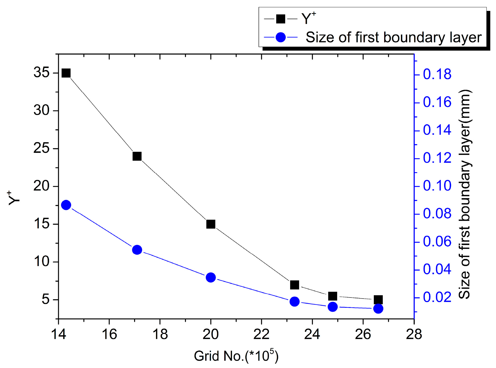
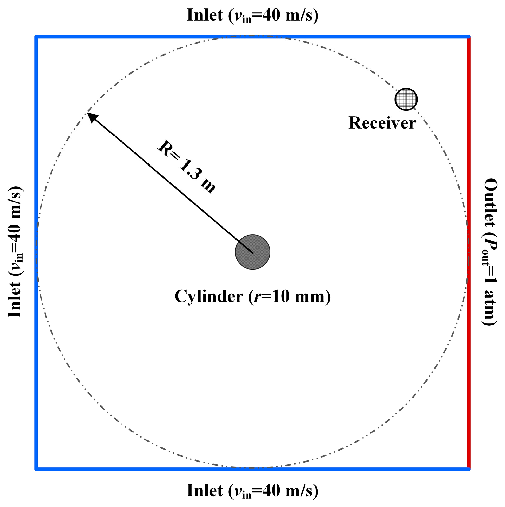
2.3. Numerical Issue Concerning the Set-Up

In this study, a single-stage single-suction centrifugal pump (media, water) having a medium specific speed of 112 is selected. Table 1 lists all the geometric and performance parameters. The 3D computational domain for the simulations comprises of the inlet pipe, impeller, and the volute, as shown in Figure 2. It should be noted that the practical disk friction losses and leakage losses are neglected, but an account is taken of the potential backflow at the inlet and outlet. A hybrid mesh system is generated using GAMBIT (2.4.6, Fluent, Inc., New York, NY, USA) [19], as shown in Figure 3. Considering the complexity of the geometrical layout and the volute tongue, an unstructured grid is used for these domains and an appropriate mesh refinement is further applied, whereas, a structured mesh is used for the remaining regions. Here, particular attention is paid to the near wall regions and the unstructured mesh is automatically refined to have appropriate y+ values (y+ ≈ 1) and thus to ensure the requirement of wall-resolved LES for the unsteady calculation [20]. It is observed that different levels of mesh refinement may lead to different average y+ values, and when the grid number reaches almost 2.5 million (2.5 M) cells, the average y+ values decrease to around 1, as shown in Figure 4. With the increase of mesh refinement, the average y+ values gradually reduce. With a combining consideration of both the mesh accuracy and the limited computing resources, the grid of 2.5 M cells is chosen for the calculation. What is more, it is not difficult to find that the average y+ values are correctly consistent with the sizes of the first boundary layer. Therefore, different grid systems shown are tested for the required grid-dependency based on the convergence pattern for the pump hydraulic head to the designed value (~28 m), as shown in Table 2. To improve the prediction accuracy while reducing the attendant computational costs, Grid-C is chosen in the study.
For the boundary conditions, a uniform axial velocity profile is imposed at the inlet while ‘outlet’ boundary conditions are adopted at the outlet. All the walls are treated as non-slip boundaries. The pre-converged steady flow field obtained via the k-ε is adopted as the initial condition for the subsequent transient wall-resolved LES simulations with a Subgrid-Scale Model of Smagorinsky-Lilly. The time step is specified by:
Δ t = 60 n K ,
where K is the step number in a rotational period of the impeller (=360 in the study), and n is the rotational speed. With the designed values given in Table 1, Δt is 1.1494 × 10⁻⁴ s in the study.

3. Results and Discussion

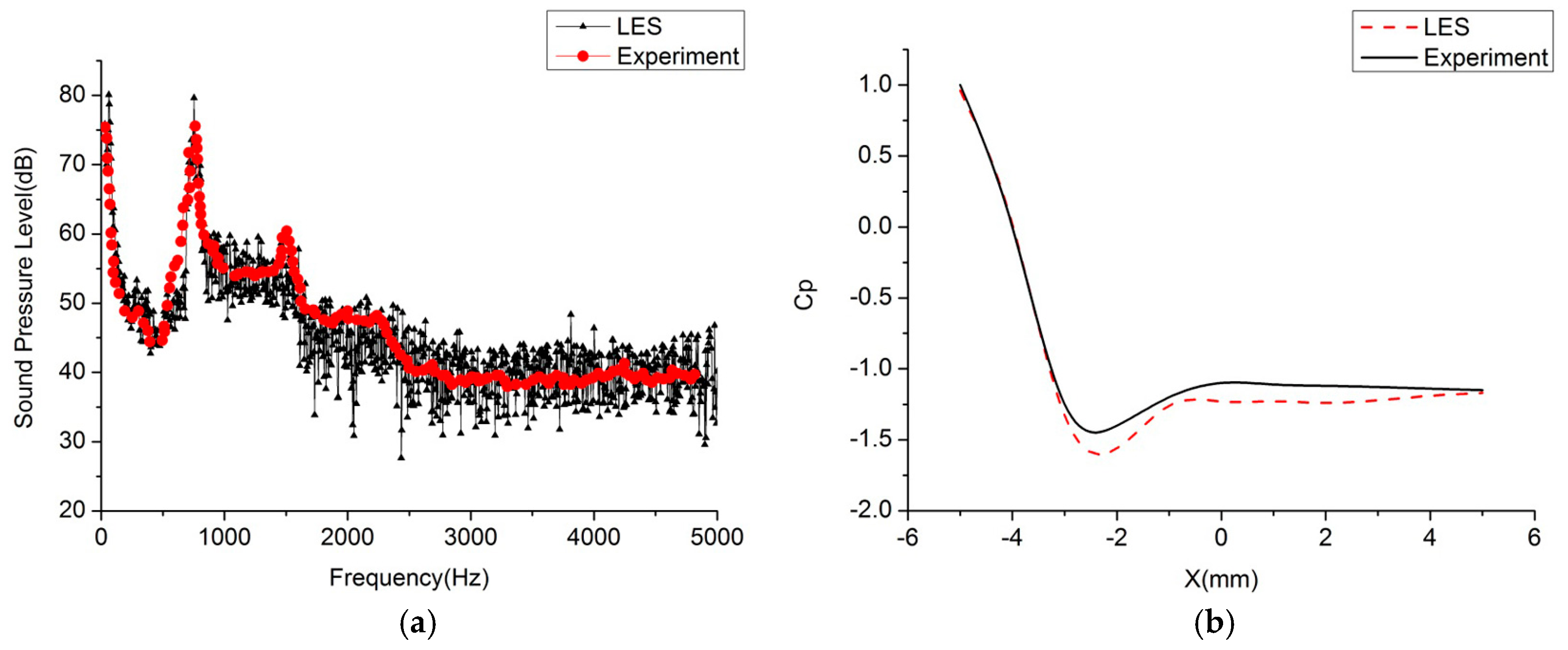
3.1. Numerical Validaton

To verify the FW-H model used, a 2D cylinder case was first studied and its computational domain and the boundary conditions are shown in Figure 5. It should be pointed out that the receiver is placed at a distance of 1.3 m from the center of the cylinder to accord with the experimental set-up [21]. A constant velocity of 40 m/s is specified at all the inlets, whereas an ambient pressure of 1 atm is used at the outlet. A structured mesh system of about 90,000 cells is used and the finest cell has a minimum edge length of 0.005 mm. Figure 6a shows the predicted and measured sound pressure spectra. As can be seen, the prediction matches rather well with the measurements at the receiver. Furthermore, the two peak frequencies at 800 Hz and 1500 Hz are adequately captured. Figure 6b displays the pressure coefficients around the cylinder surface. The simulation displays the overall trend regarding the pressure coefficient obtained in the experiment with a maximum discrepancy less than 10%.
Additionally, the numerical method adopted should also be verified. In terms of the 3D case shown in Figure 2, the hydraulic head predicted by the numerical model is compared with the nominal design head for the centrifugal pump. The simulation yields a head of 28.63 m. This prediction agrees well with the designed valued (28 m) and the relative error of the calculation is less than 2.3%. The discrepancy is essentially due to the fact that the disk friction losses and leakage losses appearing in practice are neglected in the simulations. The sound spectra for the receiver 1 in terms of the design flow rate are also shown in Figure 7. The predicted rotational frequency (APF) and blade pass frequency (BPF) are 24.1 Hz and 142.3 Hz respectively, very close to the design values of 24.2 Hz and 145 Hz marked in dashed lines. Clearly, the numerical model presented in the paper is able to yield reasonably accurate predictions on the flow field as well as the noise.

3.2. Flow Field

Throttle governing is a common control mode routinely employed in the operational envelope of the centrifugal pump system. By such means installation of the throttle employing valves or baffles and adjusting the opening of the throttle can change the local loss and achieve the desired goal of throttle governing. In this study, 13 flow rate conditions are studied to analyze the noise radiation, including 20 m3/h, 30 m3/h, 40 m3/h, 50 m3/h, 60 m3/h, 70 m3/h, 78 m3/h, 80 m3/h (which is the design flow rate), 82 m3/h, 90 m3/h, and 100 m3/h, respectively.
To elucidate the noise generation by the flow field, an index employing a value of RMS pressure field is introduced to provide information for the pressure variations with time step on the wall of the impeller and volute, Prms defined by:
P r m s = 1 N i = 0 N 1 [ P ( t ) P ¯ ] 2 ,
where P(t) represents the time-dependent static pressure, P ¯ is the time-averaged static pressure in a circulation period (N = 360 in this study).
Figure 8 describes the distribution of RMS values on the surfaces of impeller and volute. When the flow rate is 0.75 Q, the RMS pressure field primarily resides on the side of inlet, displaying values much stronger vis-a-vis the opposite side, as is shown in Figure 8a. It can be inferred from such considerations that while the flow rate is less than the design value, the velocity field distribution on the impeller is substantially non-uniform, providing for extremely unsteady flow near the inlet side vis-a-vis the outlet. Thus, the primary reason for the impeller noise is the unsteady flow field at 0.75 Q. When the flow rate reaches 1 Q, the average RMS is a minimum and the flow field is also smoothly distributed, especially near the inlet side, yielding the impeller noise under the design flow rate condition to be substantially lower than other flow rate conditions. Additionally, the RMS pressure field displays extreme values near both the inlet and the outlet regions under the 1.25 Q flow rate condition to yield a maximum noise field generated.
It can also be inferred from a study of the RMS pressure field occurring in the volute at different flow rates that the resulting acoustic behavior is rather similar to that of the impeller (seen in Figure 8b). The overall distribution of RMS at the wall of the volute under the three flow rate conditions is that the RMS values in the diffuser are unmistakably the highest and, near the volute tongue, the fluctuation field is rather “stiff”, particularly when the fluid is just transported past the tongue to flow into the volute, implying that the volute tongue is the primary source of the RMS pressure and even the noise. Although the RMS at 1 Q is smaller than those at other flow rates, the distribution resembles that under 0.75 Q and 1.25 Q flow rate conditions.

3.3. Noise Analysis

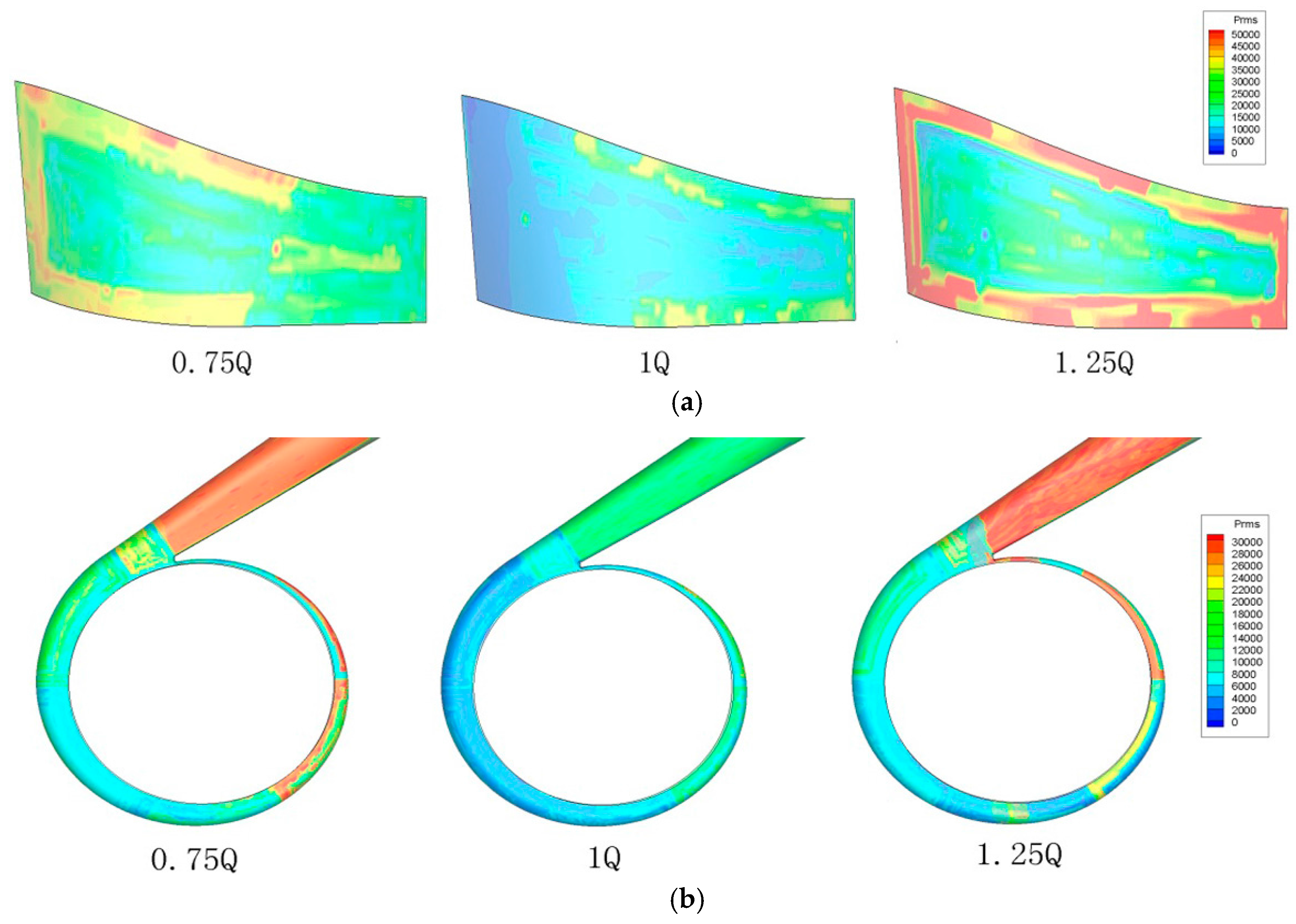
3.3.1. The Impeller Radiation Noise

The noise generated by the blades is originally studied by defining only the surfaces of the blades as the sources of sound. The distribution of impeller radiation noise for different flow rates calculated using the FW-H model is shown in Figure 9. The profiles of TSPL of directivity field shown in Figure 9a apparently demonstrate the dipole characteristic behavior. It is also found that two TSPL valleys appear at θ = 75° and 270°, but the weak asymmetric distribution occurs along these two points. Figure 9b reveals that the design operation (1 Q) generates the smallest TSPL than off-design operations. As the flow rates decrease from 1 Q to 0.25 Q, the TSPL initially increases significantly before 0.75 Q and then level off afterwards. A similar trend occurs for the cases for the larger flow rates (1–1.25 Q), but the TSPL increases very quickly. For example, the 1.25 Q case produces much more noise in comparison with 0.75 Q, even though they have the same off-design deviation. In general, the noise level deviates about 50% in different directions as demonstrated by the deviation bar in Figure 9b. Nevertheless, the TSPL is eventually saturated at ~70 dB with the increase/decrease of the flow rate.

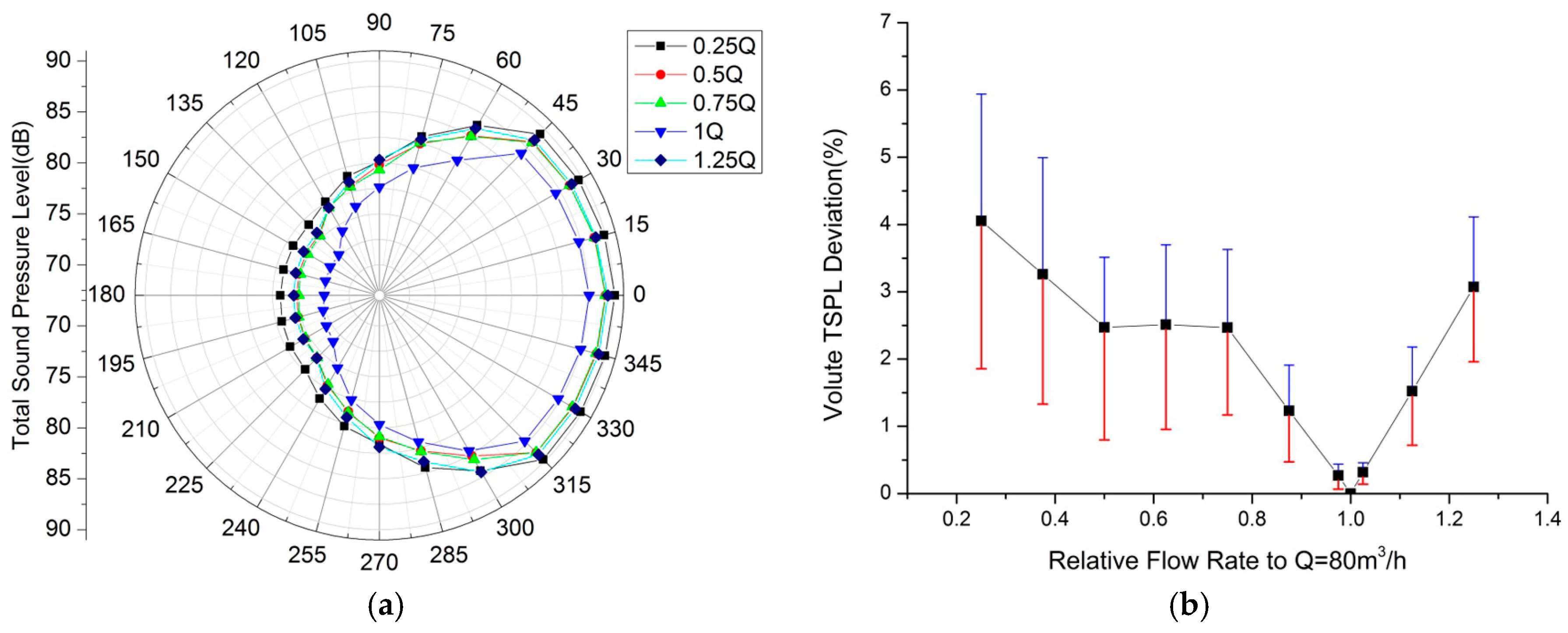
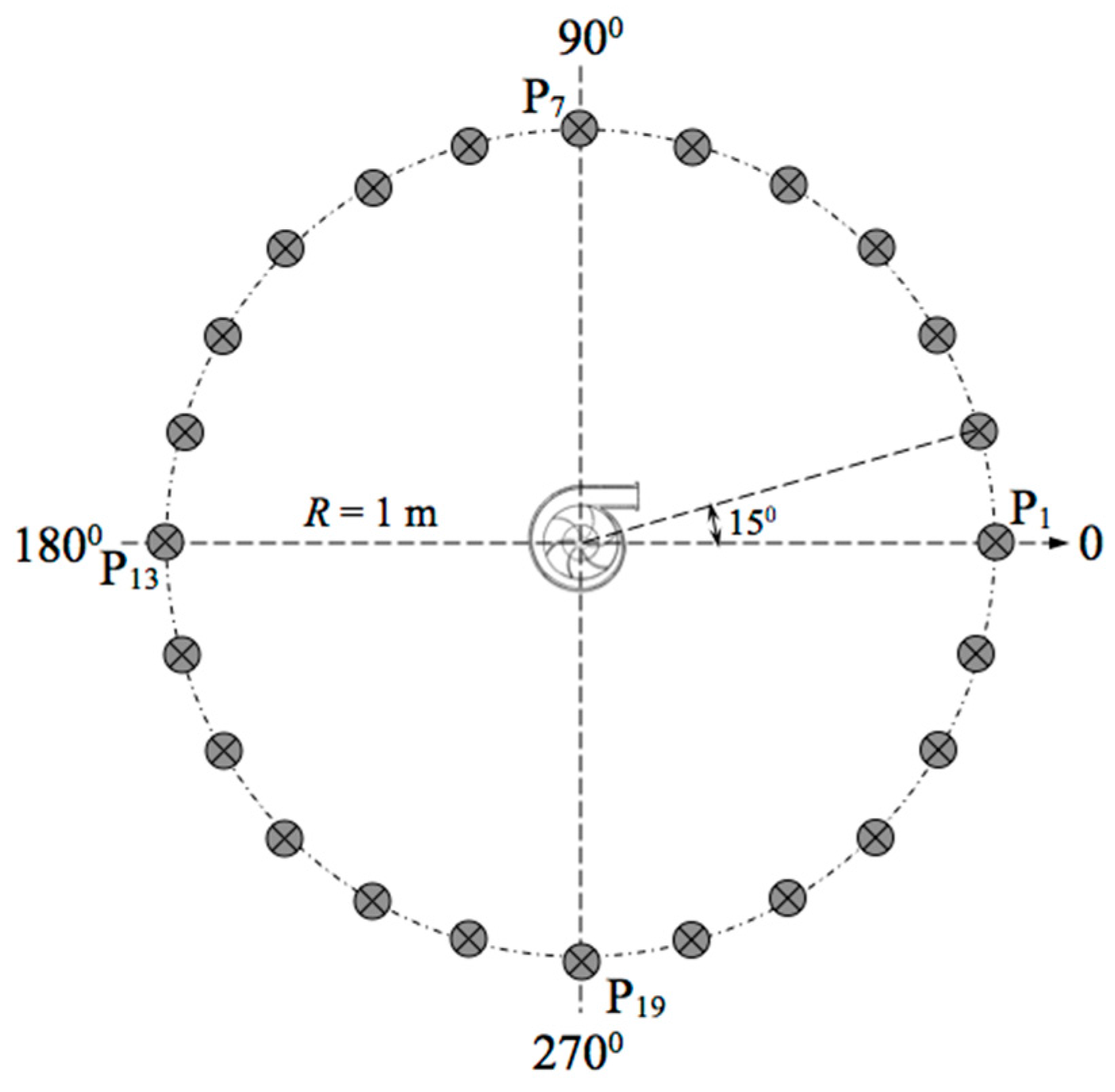
3.3.2. The Volute Radiation Noise

Similarly, the noise generated by the volute is further studied by defining the volute surface as the source of sound. Figure 10a shows the TSPL pattern for the volute radiation noise. Interestingly, the radiation field displays very different behavior in comparison with the blade noise discussed above. The TSPL profiles exhibit an apparent asymmetric behavior and TSPL on the right hand side is much larger than the one on the left. This may be explained by the fact that the volute tongue is the key noise source and the non-uniform distance between the receivers and the tongue leads to the asymmetric distribution. Figure 10b reveals a similar trend shown in Figure 9b. It is interesting to find that the mean TSPL levels off in the range of 0.5–0.75 Q. With the increase/decrease of the flow rate vis-a-vis the design value, the TSPL deviation increases and the maximum is about 50%. It should be noted that the TSPL can reach ~87 dB, which informs us that the noise contribution by the volute is substantial.

4. Conclusions

In terms of a single-stage singe-suction centrifugal pump, a 3D numerical model with the LES closure is developed for elucidation and reliable prediction of the pertinent hydro/aero acoustic behavior. In particular, the FW-H model was employed to predict the noise generation by the blades as well as the volute. Comparisons of numerical predictions with the measured/analytical results reveal that the model can yield good results on the noise and the flow field. The simulations further show that the interaction of the blades with the volute induces high RMS pressure and further leads to additional noise radiation. Moreover, the sources of noise generated by the blade surfaces and the volute surface at different flow rates were studied. It is found that the profiles of TSPL of directivity field for the impeller-generated noise demonstrate a typical dipole characteristic behavior, whereas the ones for the volute-generated noise exhibit an apparent asymmetric behavior. In addition, within the flow rate range studied, the design operation (1 Q) generates the smallest TSPL than off-design operations. As the flow rates decrease from 1 Q to 0.25 Q, TSPL initially increases significantly before 0.75 Q and then levels off afterwards. A similar trend occurs for the cases in the larger flow rates (1–1.25 Q). The TSPL deviates with the radiation directivity and the maximum is about 50%. It is also found that TSPL by the volute and the blades can reach ~87 dB and ~70 dB at most, respectively.

Acknowledgments

Shenghui Lei would appreciate the financial support by the Industrial Development Agency (IDA) Ireland.

Author Contributions

Ming Gao conceived the initial idea of this research and guided the work; Peixin Dong carried out the simulations and collected and analyzed the data; Shenghui Lei analyzed the data and guided the simulations; Ali Turan contributed valuable scientific discussion; all the authors commented and wrote the paper.

Conflicts of Interest

The authors declare no conflict of interest. The founding sponsors had no role in the design of the study; in the collection, analyses, or interpretation of data; in the writing of the manuscript, and in the decision to publish the results.

Nomenclature

CsSmagorinsky constant
ΔSize of the grid filter
p’Far-field acoustic pressure
a0Speed of sound
ρ 0 Reference density of fluid
δ(f)Dirac delta function
H(f)Heaviside function
PrefReference sound pressure
KStep number in a rotational period
nRotational speed
P(t)Transient static pressure
P ¯ Time-averaged static pressure

References

  1. Johann, F.G. Centrifugal Pumps; Springer: Berlin/Heidelberg, Germany; New York, NY, USA, 2008. [Google Scholar]
  2. Brennen, C.E. A review of the dynamics of cavitating pumps. J. Fluids Eng. 2012, 135. [Google Scholar] [CrossRef]
  3. Wang, J.; Feng, T.; Liu, K.; Zhou, Q.J. Experimental research on the relationship between the flow-induced noise and the hyaraulic parameters in centrifugal pump. Fluid Mach. 2007, 6, 1–13. [Google Scholar]
  4. Choi, J.S.; Mclaughlin, D.K.; Thompson, D.E. Experiments on the unsteady flow field and noise generation in a centrifugal pump impeller. J. Sound Vib. 2003, 263, 493–514. [Google Scholar] [CrossRef]
  5. Parrondo, J.; Pérez, J.; Barrio, R.; González, J. A simple acoustic model to characterize the internal low frequency sound field in centrifugal pumps. Appl. Acoust. 2011, 72, 59–64. [Google Scholar] [CrossRef]
  6. Liu, H.L.; Dai, H.W.; Ding, J. Numerical and experimental studies of hydraulic noise induced by surface dipole sources in a centrifugal pump. J. Hydrodyn. Ser. B 2016, 28, 43–51. [Google Scholar] [CrossRef]
  7. Chu, S.; Dong, R.; Katz, J. Relationship between unsteady flow, pressure fluctuations, and noise in a centrifugal pump—Part A: Use of PDV data to compute the pressure field. J. Fluids Eng. 1995, 117, 24–29. [Google Scholar] [CrossRef]
  8. Chu, S.; Dong, R.; Katz, J. Relationship between unsteady flow, pressure fluctuations, and noise in a centrifugal pump—Part B: Effects of blade-tongue interactions. J. Fluids Eng. 1995, 117, 30–35. [Google Scholar] [CrossRef]
  9. Langthjem, M.A.; Olhoff, N. A numerical study of flow-induced noise in a two-dimensional centrifugal pump. Part I. Hydrodynamics. J. Fluids Struct. 2004, 19, 349–368. [Google Scholar] [CrossRef]
  10. Langthjem, M.A.; Olhoff, N. A numerical study of flow-induced noise in a two-dimensional centrifugal pump. Part II. Hydroacoustics. J. Fluids Struct. 2004, 19, 369–386. [Google Scholar] [CrossRef]
  11. Kato, C.; Yamade, Y.; Wang, H.; Guo, Y.; Miyazawa, M.; Takaishi, T.; Takano, Y. Numerical prediction of sound generated from flows with a low Mach number. Comput. Fluids 2007, 36, 53–68. [Google Scholar] [CrossRef]
  12. Kato, C.; Kaiho, M.; Manabe, A. An overset finite-element large-eddy simulation method with applications to turbomachinery and aeroacoustics. Trans. Am. Soc. Mech. Eng. J. Appl. Mech. 2003, 70, 32–43. [Google Scholar] [CrossRef]
  13. Huang, J. Comparison of noise characteristics in centrifugal pumps with different types of impellers. Acta Acust. 2010, 35, 113–118. [Google Scholar]
  14. Li, K.; Yu, J.; Shi, F.; Huang, A.X. Dimension splitting method for the three dimensional rotating Navier-Stokes equations. Acta Math. Appl. Sin. Engl. Ser. 2012, 28, 417–442. [Google Scholar] [CrossRef]
  15. Seif, M.S.; Asnaghi, A.; Jahanbakhsh, E. Implementation of PISO algorithm for simulating unsteady cavitating flows. Ocean Eng. 2010, 37, 1321–1336. [Google Scholar] [CrossRef]
  16. Williams, J.F.; Hawkings, D.L. Sound generated by turbulence and surfaces in arbitrary motion. Philos. Trans. R. Soc. A Math. Phys. Eng. Sci. 2010, 264, 321–342. [Google Scholar] [CrossRef]
  17. Ghasemian, M.; Nejat, A. Aerodynamic noise prediction of a horizontal axis wind turbine using improved delayed detached eddy simulation and acoustic analogy. Energy Convers. Manag. 2015, 99, 210–220. [Google Scholar] [CrossRef]
  18. Tao, J.; Lu, X.; Wang, L.; Wang, L.; Li, J. Methods of Measuring and Evaluating Noise of Pumps; Chinese Quality Supervision Bureau: Beijing, China, 2013; pp. 4–6. [Google Scholar]
  19. Fluent Inc. Gambit 2.4 User’s Guide; Fluent Inc.: New York, NY, USA, 2007; pp. 1–17. [Google Scholar]
  20. Choi, H.; Moin, P. Grid-point requirements for large eddy simulation: Chapman’s estimates revisited. Phys. Fluids 2012, 24. [Google Scholar] [CrossRef]
  21. Tsai, C.H.; Fu, L.M.; Tai, C.H.; Huang, Y.L.; Leong, J.C. Computational aero-acoustic analysis of a passenger car with a rear spoiler. Appl. Math. Model. 2009, 33, 3661–3673. [Google Scholar] [CrossRef]
Figure 1. Arrangement of receivers outside the centrifugal pump.
Energies 10 00221 g001
Figure 2. Computational geometry of the centrifugal pump for each part.
Energies 10 00221 g002
Figure 3. Grid System of the centrifugal pump. (a) Overall view; and (b) magnified view of the volute tongue.
Energies 10 00221 g003
Figure 4. Y+ values and corresponding sizes of first boundary layer.
Energies 10 00221 g004
Figure 5. The validation case of a 2D cylinder (not to scale).
Energies 10 00221 g005
Figure 6. Comparison of numerical predictions with experimental measurements. (a) Sound pressure spectra; and (b) pressure coefficient (Cp).
Energies 10 00221 g006
Figure 7. The sound spectra of receiver 1.
Energies 10 00221 g007
Figure 8. Distribution of root mean square (RMS) value on both impeller and volute under three separate flow rates, including 0.75 Q, 1 Q and 1.25 Q. (a) Distribution of RMS value on impeller; and (b) distribution of RMS value on volute.
Energies 10 00221 g008
Figure 9. Impeller radiation noise. (a) Total sound pressure level (TSPL) of directivity field from the impellers; and (b) the relationship of TSPL deviation vs. the flow rate.
Energies 10 00221 g009
Figure 10. Volute radiation noise. (a) Total sound pressure level of directivity field from the volute; and (b) the relationship of TSPL deviation vs. the flow rate.
Energies 10 00221 g010
Table 1. Geometric and performance parameters used for a simulated centrifugal pump (water).
ParameterValueUnit
Impeller outlet diameter D2270mm
Impeller outlet width D30mm
Design flow rate Q80m3/h
Design head H28m
Design rotational speed n1450r/min
Blade number Z61
Axis pass frequency fa (APF)24.2Hz
Blade pass frequency fb (BPF)145Hz
Table 2. Grid independent Analysis.
Grid SystemGrid NumberHead (m)
Grid-A2,012,65828.82
Grid-B2,324,56728.70
Grid-C2,496,54328.63
Grid-D2,676,32828.62

