1. Introduction
Fluctuations of the distributed voltages and reactive power are one of the most common problems in the operation of large scale wind farms, as the internal voltages inside wind farms can be affected by the network parameters and wind speed under normal operations. The increasingly severe impacts of the voltage faults at the terminals of generators can lead to off-grid events of the wind generation system. Therefore, the stabilization of distributed voltages along feeder lines and the safety operation of wind farms in the weak AC grid have become major concerns on the autonomous energy internet.
Conventionally, centralized reactive power compensators are widely used at the point of common coupling (PCC) of the wind farms, such as a static var compensator (SVC), static synchronous compensator (STATCOM), etc. [
1,
2]. With the increasing amount of doubly-fed induction generator (DFIG) and permanent-magnet synchronous generator (PMSG) wind turbines installed in the wind farms, significantly more research has focused on the voltage regulations of the generator terminals and the local compensation of the distributed reactive power [
3,
4]. The hierarchical voltage control methods, based on the reactive power regulations of the variable-speed constant-frequency (VSCF) wind turbines, have been discussed in [
5,
6,
7]. The coordinated control of centralized compensators and distributed wind generators were studied in [
8,
9]. Moreover, the multi-objective optimization models, including wind generators, STATCOM, and on load tap changing (OLTC) devices, were proposed in [
10]. Most of the proposed reactive power compensation methods are based on the absolute voltage error or the fixed power factor, which are similar to the compensation strategy of the conventional generators. It is noted that all of the voltage control methods that are discussed in this paper are applied under normal operations of the wind farm, to maintain the stability of the internal voltages on the terminals of key equipment and feeder lines. This is different to low voltage ride-through (LVRT) methods, which are only applied under fault operations.
However, in contrast to the conventional power plant, the large scale wind farm is composed of various wind generators, whose rated output power is much smaller than the synchronous generators which are connected to the grid. Also, the reactive power capacity of the generation unit inside the wind farm is far less than the reactive power deficit when the grid voltage fault occurs. Thus, the reserved reactive power capacity of each unit cannot always maintain its terminal voltage at a constant value. Moreover, the power flow analysis of the wind farm mainly uses the algebraic accumulation of the reactive power, which is provided from compensation units as the equivalent compensated reactive power at the PCC [
11,
12]. However, the changes of the voltage phase angle along the feeder lines cannot be neglected, as the voltage distributions inside the wind farm are mainly caused by the inductance of the network. Also, as the wind farm always covers a wide area with scattered wind generators, the distribution features of the network are no longer negligible. Compared with the voltage regulation time of the power system, which is generally within tens of milliseconds, the consumed time for the conventional voltage control under master-slave mode would be greatly increased to the level of milliseconds. Therefore, it would further exacerbate the stability of the system’s voltage, and even lead to power oscillations inside the wind farm. Therefore, the power flow analysis and voltage regulations inside the wind farm remain stringent issues [
13].
In order to improve the dynamic performance of the internal voltage regulation inside the wind farm, as well as realize the local reactive power compensations without remote communication, the approach in this paper proposes compensating the reactive power based on the observations of local relative voltage errors. Firstly, the transfer functions of the reactive power and distributed voltages were analyzed, considering the changes in the voltage phase angle and fully network parameters. Then, observations of the local relative voltage errors are proposed, on the basis of the known constructions and parameters. Based on this method, the transfer characteristic of the voltages could enable every compensation node to track the voltage amplitude of the previous node all the way up to the PCC, without the need for centralized reactive power commands. Moreover, the optimal configuration for each compensator is discussed in relation to the limited reactive power capacity of the wind farm. Additionally, the proposed method could improve the voltage regulation time and system stability, without requiring communication between each compensator.
The rest of the paper is organized as follows. The distributed voltage transfer functions are outlined in
Section 2. The coordinated voltage control, based on the local reactive power compensation, is provided in
Section 3. The stability analysis of such a voltage control method is discussed in
Section 4, and the simulation results for the wind power in North Hebei, China, are elaborated in
Section 5, with conclusions drawn in
Section 6.
2. Distributed Voltage Transfer Functions
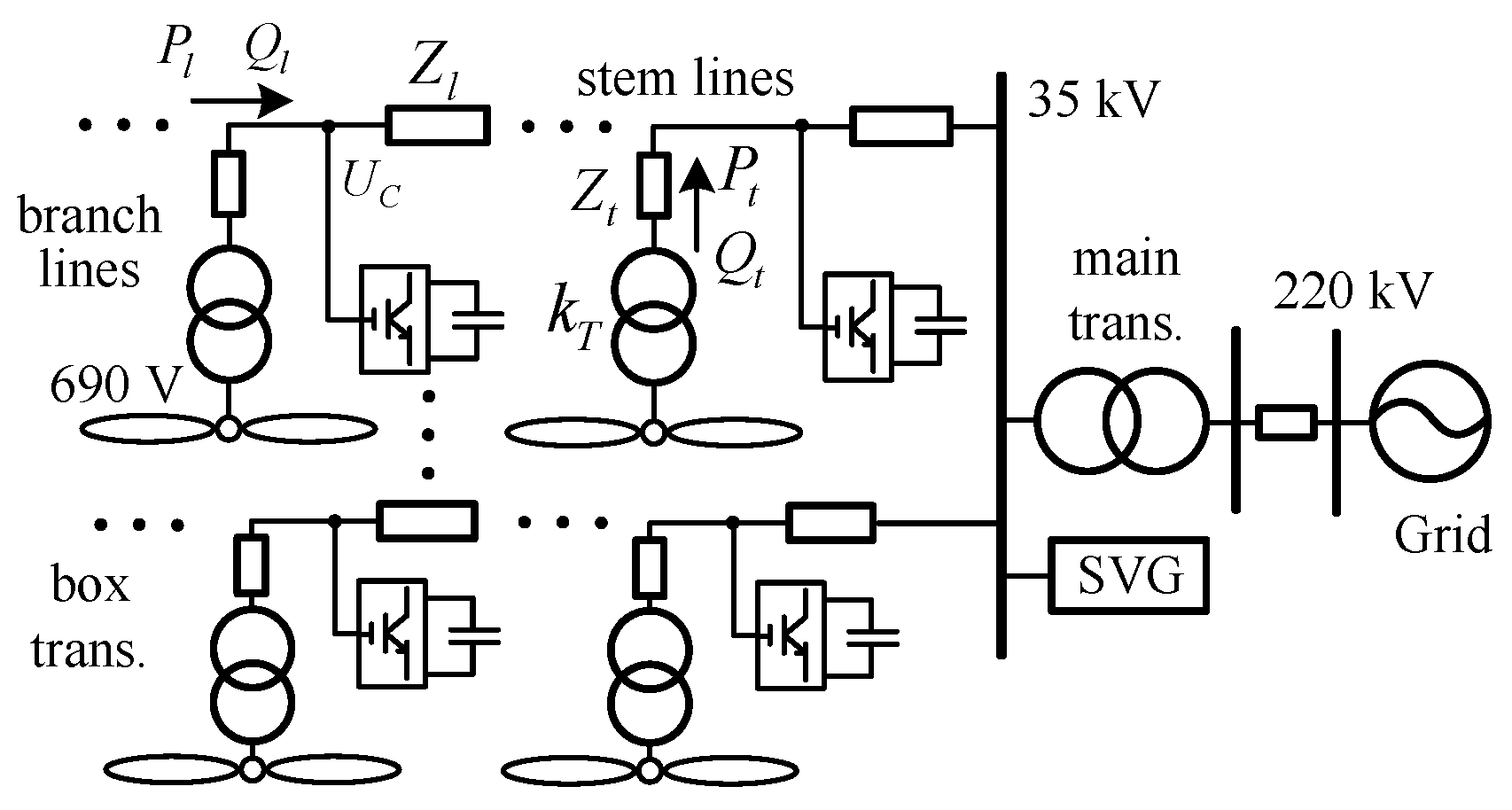
The basic construction types of wind farms include radial structure, unilateral ring structure, bilateral ring structure, and composite ring structure. As a radial pattern has the advantages of a simple construction, convenient operation, and low cost, it has been widely used in wind farms across China, as shown in
Figure 1.
As can be seen for the typical radial structure shown in
Figure 1, the terminal voltage of the wind generator is usually set at 690 V, and is boosted to the 35 kV branch lines through its box transformer. The scattered generation units converge to the stem lines, and inject the active and reactive power to the 220 kV grid through the main transformer at the PCC. A static var generator (SVG) or a SVC is always connected to the PCC, to regulate its voltage at the required base voltage value. Moreover, as the distributed voltages may fluctuate along the feeder lines, and in order to confine the terminal voltage of the generator within a safety operation margin, the reactive power compensators could be installed at the key confluence nodes.
2.1. Mathematical Model
Considering the feeder lines are generally less than 100 km, the capacitance effect of the transmission line can be neglected. The parameters of the branches and stems can be expressed as
. Additionally, when the excitation impedance is comparatively larger than the leakage impedance, the parameters of the transformer can be expressed as
. The nominal voltage is set as the nominal voltage of the PCC. A typical voltage transfer function between adjacent nodes is expressed in Equation (1). Assuming that the impedance between the adjacent nodes A and B is
, the injected power from A to B is
.
where
and
are the magnitudes and phase angles of the nodes A and B, respectively. The voltage drop in phase with
is the direct voltage, and the voltage drop with a 90 degree lag is the quadrature voltage. It is clear that the phase angles of the voltages vary along the feeder lines, and instead of applying the conventional model by algebraically accumulating the distributed reactive power at the PCC, the distributed voltages can be obtained by the iterations from the generation units to the branches and stems, up until the PCC. According to Equation (1), the ratio between the direct voltage and quadrature voltage is defined by the short-circuit ratio and impedance ratio. When
and the power flow from A to B are both 1 p.u., the voltage error of
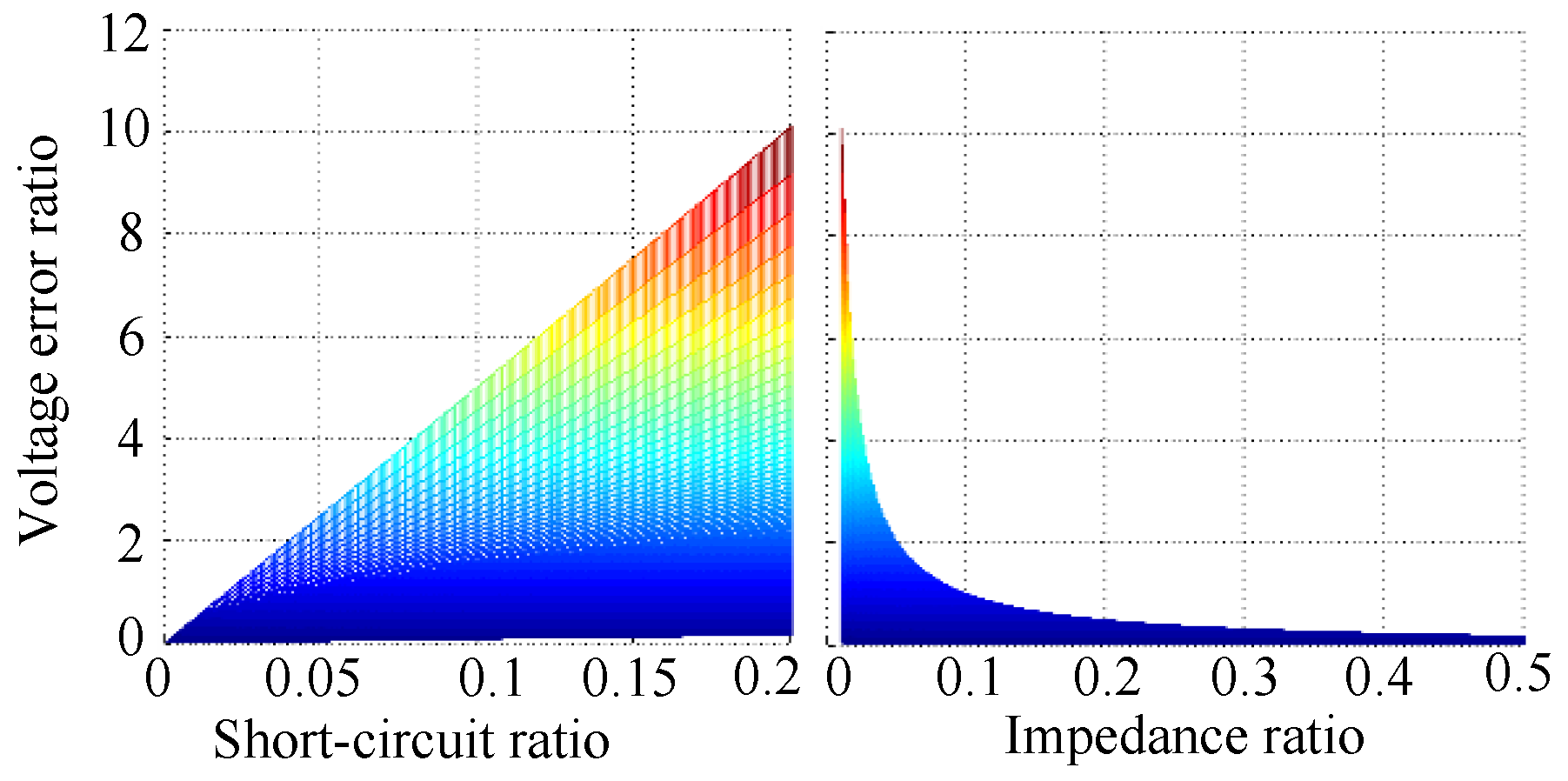
is calculated by neglecting the direct voltage and quadrature voltage, respectively. Moreover, the ratios of these two errors are shown in
Figure 2, with the short-circuit ratio varying from 0% to 20%, and the impedance ratio varying from 0.1% to 50%.
If the ratio is between 0.1 and 10, it means that the voltage drops of both the direct and quadrate axis are of the same scale, and none of them can be neglected. If the ratio is larger than 10, the quadrate voltage is negligible, while if it less than 0.1, the direct voltage is negligible. Considering the variation ranges of the real parameters, the short-circuit ratio is about 0.5% to 1%, and the impedance ratio is around 0.1 to 0.4 for the feeder lines in the wind farms. When considering the transformers, the short-circuit ratio is about 4% to 8%, and the impedance ratio is around 0.02 to 0.05 [
14,
15]. The principle of reactive power compensation comprises the use of the voltage item
, which is generated from the reactive power through the inductance, to compensate the item
, generated by the variation of active power. The feature of the low impedance ratio enables the small reactive power to compensate for a larger voltage drop, caused by the variations of active power. It can be concluded from
Figure 2 that the item of reactive power in the quadrate voltage can be neglected under most circumstances. In sum, the simplified transfer functions between adjacent nodes in the wind farm can be expressed as:
The feasibility and accuracy of the proposed methodology are based on the parameters of cable lines, and the detected voltage and current. Firstly, the accuracy of the voltage and current data is confined by the sampling precisions, which are usually within 1% for the common sensors. Then, for the cable lines and transformers, the parameters are basically constant with the same line type, physic material, and operation frequency. Furthermore, for the transformers, the data of the short circuit ratio, no-load current, and load loss, are also tested and provided by the manufacturers. After the construction of the wind farm, the length and positions of all of the cables and transformers are fixed. Thus, the parameters are reachable under normal operations.
2.2. Objectives and Constrains of the Voltage Control
The control objectives consist of the voltage of PCC and the terminal voltages of wind generators. The PCC voltage can be affected by a change of wind power, grid voltage disturbances, and as the reference voltage of the wind farm, the stability of the PCC voltage is of great importance. Meanwhile, as the generators need to send the wind power to the grid through a series of transformers and feeder lines, the variations of wind power could change the voltage distribution feature along the transmission paths, thus inducing fluctuations of the generator’s terminal voltage. The stability of the terminal voltage ensures that the generation unit does not off-grid. The constraint function of the voltages can be written as:
where
is the voltage of the PCC or terminals of the generators,
is the reference voltage, and
is the error limit. These objectives can be achieved by the compensators installed at the PCC or key node along the feeder lines. To ensure the reliable operation of the compensators, the margin indices of the reactive power
and voltage
are taken into consideration, as:
where
and
are the present value and reference of the reactive power, respectively, and
and
are the reactive power limits of the compensators.
is the weight coefficient of the reactive power. Moreover, the voltage function has a similar definition for each corresponding symbol. It can be seen that the limits of the reactive compensator can determine whether the voltage requirements can be maintained. Considering the capacity of the grid is usually much larger than the wind farm, the voltage fluctuations caused by the grid cannot always be fully compensated by the wind farm, when the deficit exceeds the limits of all the reactive power compensators. Under such circumstances, the voltage loops are operated at the saturation mode, which leads to an uncontrollable state and exacerbates the voltage stability of a series of nodes inside the wind farm. Therefore, a relative voltage control, based on the local reactive power regulation, is proposed.
4. Stability Analysis of the Voltages inside the Wind Farm
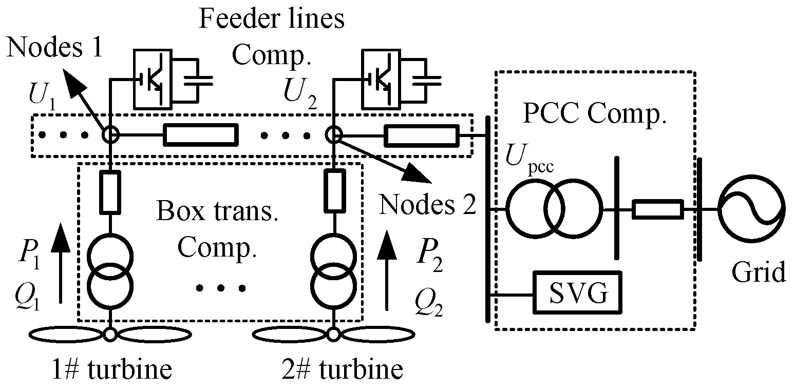
The proposed relative voltage control can theoretically coordinate all the voltages of the wind farm through local reactive power control. However, such distributed control, which involves multiple compensation nodes, would not easily reveal the stability and dynamic performance. Thus, the stability analysis is further studied in this section. As the regulations are achieved by the PI controllers embedded in the distribution compensators, the stability of these control loops can affect the stability of the wind farm. Stability analysis is based and applied on the system consisting of two generators, as shown in
Figure 3. Assuming the voltage of the PCC is constant, the output active power of the 1# wind generator
is set as the disturbance, and the voltage of the 2# wind generator
is set as the observation. Considering that the voltage transfer function has the quadric expressions of the disturbance variables, the stability analysis is initially studied based on linearized equations, and then its performance is analyzed by using the local linearization. The voltage relationship and reactive power equations are expressed as:
where the variables are in accordance with
Figure 3, and
,
and
,
are the PI parameters of the installed compensators in Node 1 and Node 2, respectively. Then, the transfer function from
to
can be obtained by iterating Equation (9).
The dominant poles of the transfer function are
,
. As the parameters of the impedance and PI controllers are all positive, the poles are located in the negative half of the plane, which shows the global stability of the system. Moreover, when applying the whole nonlinear function as Equation (2), the
can be expressed in the second-order form, with a voltage of PCC that is equal to the nominal value:
Then, the equation is expanded and locally linearized at the operation point
, as follows:
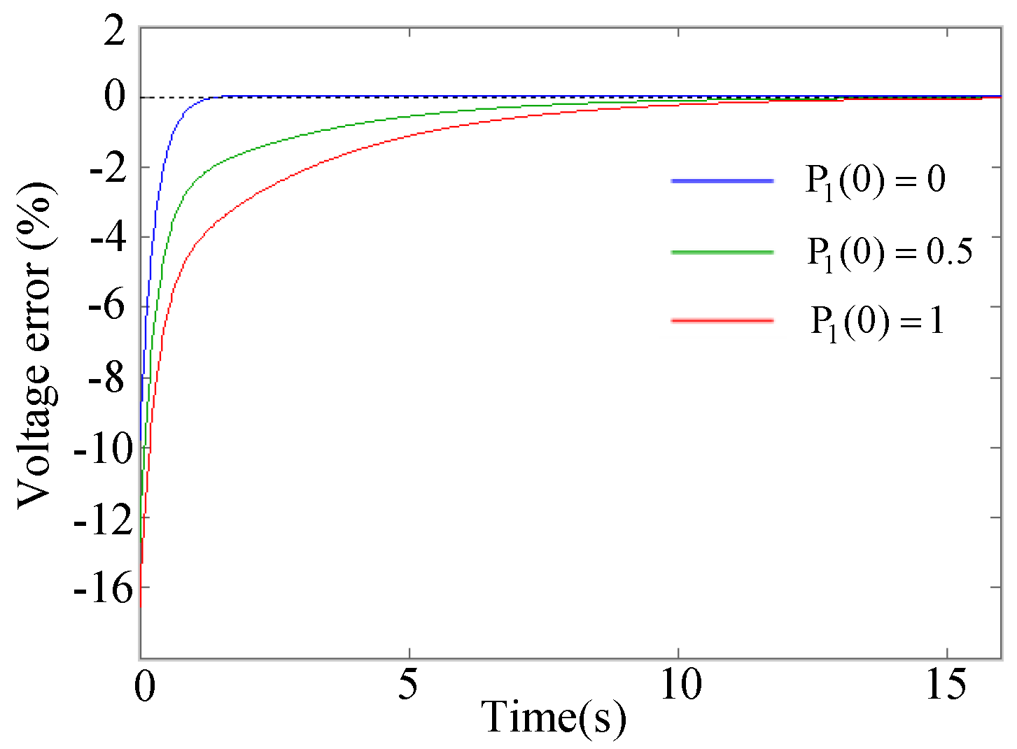
Compared with the linearized transfer function, the dominating poles of the local linearized function are still located in the left half of the plane. Then, the perturbation observations under different initial operation points of
, are shown in
Figure 4.
From the figures above, it is clear that the step responses of are convergent when is set as 0, 0.5, and 1, respectively. Thus, the voltages inside the wind farm, which obey the nonlinear transfer function, can still have a fairly big stability margin under the proposed relative voltage control. However, the stability of each node voltage under the conventional voltage control based on the absolute value, is constrained by the upper centralized controller which needs to sample, calculate, and transfer a huge amount of data from the distributed wind generation unit and various nodes on the feeder lines. Under the large disturbance from grid-side or turbine-side, the transmission speed of the instructions for the voltage and reactive power usually takes tens of milliseconds, while the voltage control speed for the grid is usually at the level of milliseconds, and the oscillations of voltage and reactive power frequently occur. The proposed relative voltage control equips the reactive power compensations with fast and stable features, which are highly valued in practical application.
5. Simulation Results
The parameters and constructions of the simulation model are obtained from a specific wind farm in North Hebei, China, as is shown in
Figure 1. The whole installed capacity of the wind farm is 49.5 MVA, which includes 33 wind generation units. The parameters of the feeder lines, main transformer, and box transformers, are elaborated in the
appendix. The traditional wind farm has a radial structure consisting of three feeder lines, A, B, and C, which lie parallel at the PCC. Each of these feeder lines has 12, 12, and nine wind turbines connected in series, respectively. As the voltages of the PCC determine the base value of all the voltages inside the wind farm, and the terminal voltages of generators assure the safety operation and grid-connected mode of generation units, the priority of these voltages should also be taken into consideration. To elaborate the effects of the proposed voltage control methods, they can be further divided into four categories, represented as S1 to S4, while considering the voltage priorities. These control strategies are all compared with the conventional absolute voltage value control, which is represented by Conventional in the figures.
- (1)
Relative voltage control is applied at the PCC (S1).
- (2)
Relative voltage control is applied at the PCC and the terminals of the generators (S2).
- (3)
Relative voltage control is applied at the PCC, the terminals of the generators, and the key nodes along the feeder lines (S3).
- (4)
Relative voltage control is applied at the locations as category 3 under a limited reactive power capacity (S4).
5.1. Relative Voltage Control at PCC of the Wind Speed
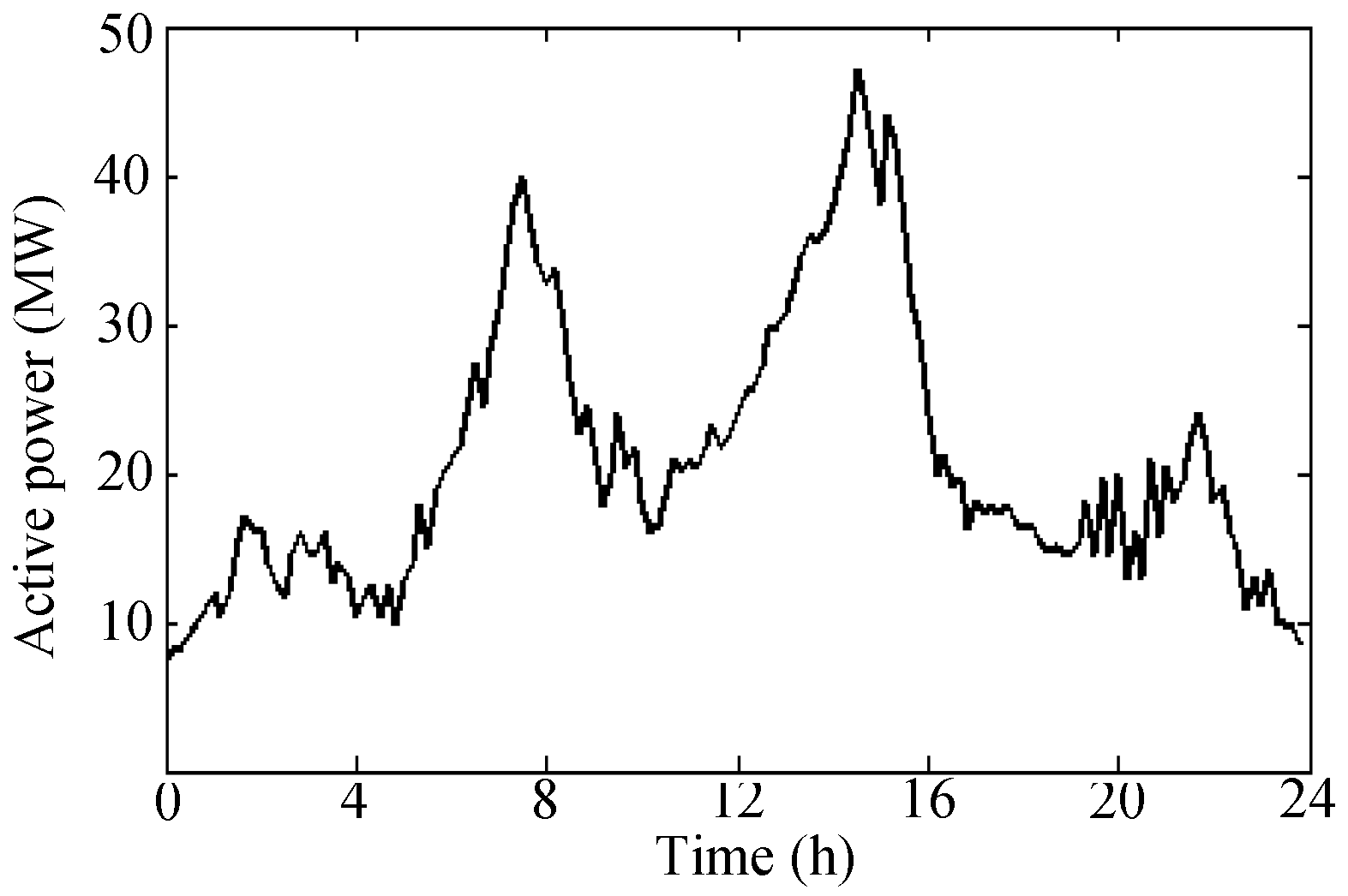
A typical daily active wind power curve of the wind farm in North Hebei is set as the active output power at the PCC, which is shown in
Figure 5. In order to reflect the difference between the absolute voltage value control and relative voltage control, the grid voltage is fixed at 0.98.
The absolute value of the PCC voltage is used in the conventional reactive compensation strategy. The PCC voltage reference value in this method is usually given according to the system schedule set to the 1 per-unit (p.u.) in the simulation.
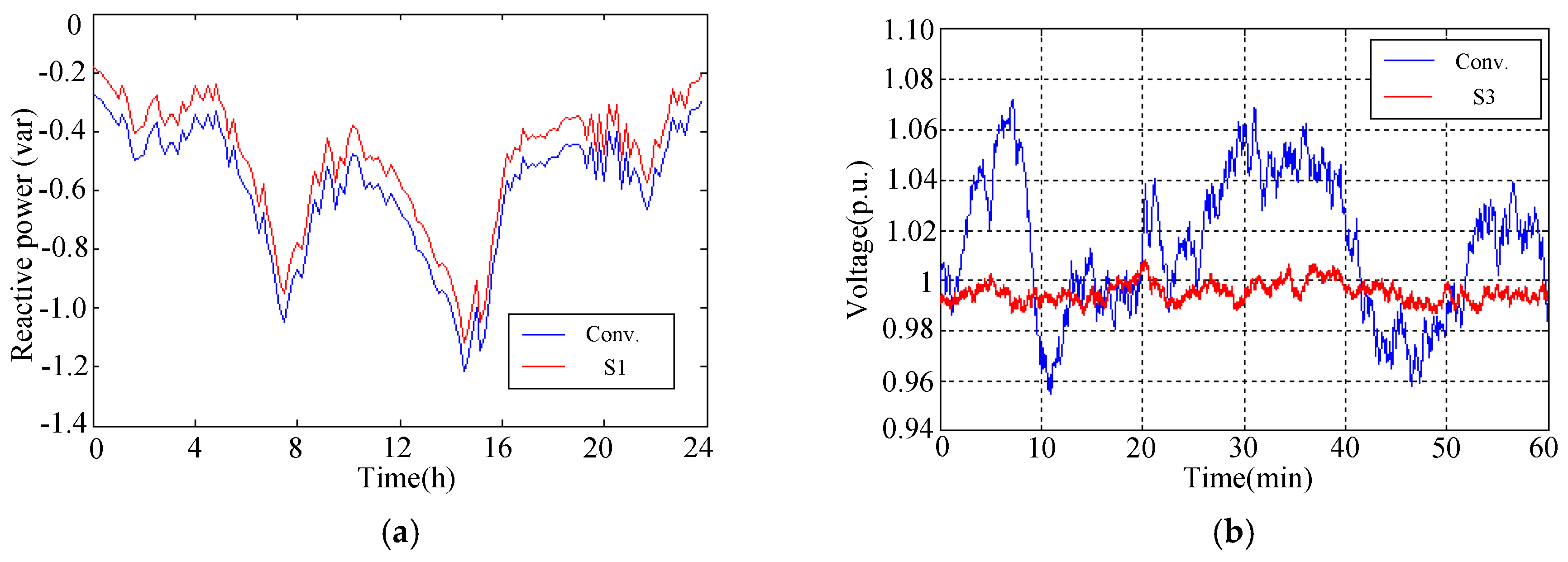
Figure 6a shows the comparisons of reactive power compensation under absolute voltage control and relative voltage control, at the PCC point. It can be seen from
Figure 6a that if the wind farm only needs to meet the voltage requirement at the PCC, then control strategy 1 can cause the wind voltage to fluctuate slightly, with the grid voltage under normal operating conditions. The voltage control of the wind farm would only compensate for the voltage drop caused by the active fluctuations of the wind generators, and would not actively support the reactive power loss of a grid with a higher capacity level. Therefore, the reactive power compensation is more effective than the traditional absolute voltage compensation. While the absolute voltage control may cause oscillations when the grid voltage deviates from the rated value, the reactive power compensators cannot be compared with the grid capacity and this demonstrates its limitation. In this paper, the reactive power capacity and voltage margins of the wind farm taken into account the relative voltage control, which is more reasonable than the traditional absolute voltage control.
When the wind farm requires the global control of the voltage, it is necessary to assemble the terminals of the generators and the key confluence nodes with the reactive power compensators. The conventional method needs to realize the reactive power schedule through the centralized control calculation, and the updating cycle of the instructions takes about 80 ms due to the long distance and huge data transmission, while the proposed strategy S3 can increase its control cycle to 3 ms for it is based on local parameters and observed signals. The PCC voltage fluctuations of the above two strategies are shown in
Figure 6b, and the voltage level is set at 35 kV (1.0 p.u.).
It can be seen that it is necessary to install the distributed compensators at all key nodes to realize the global voltage control of the wind farm. Also, the PCC voltage under the conventional control method will fluctuate more drastically, due to the delay of the control signal, and the local reactive power compensation based on the relative voltage observation can realize the global control of the wind farm, without centralized dispatching. This demonstrates a strong advantage in terms of faster compensation and more stable voltage regulation.
5.2. Voltage Distributions of the Wind Farm
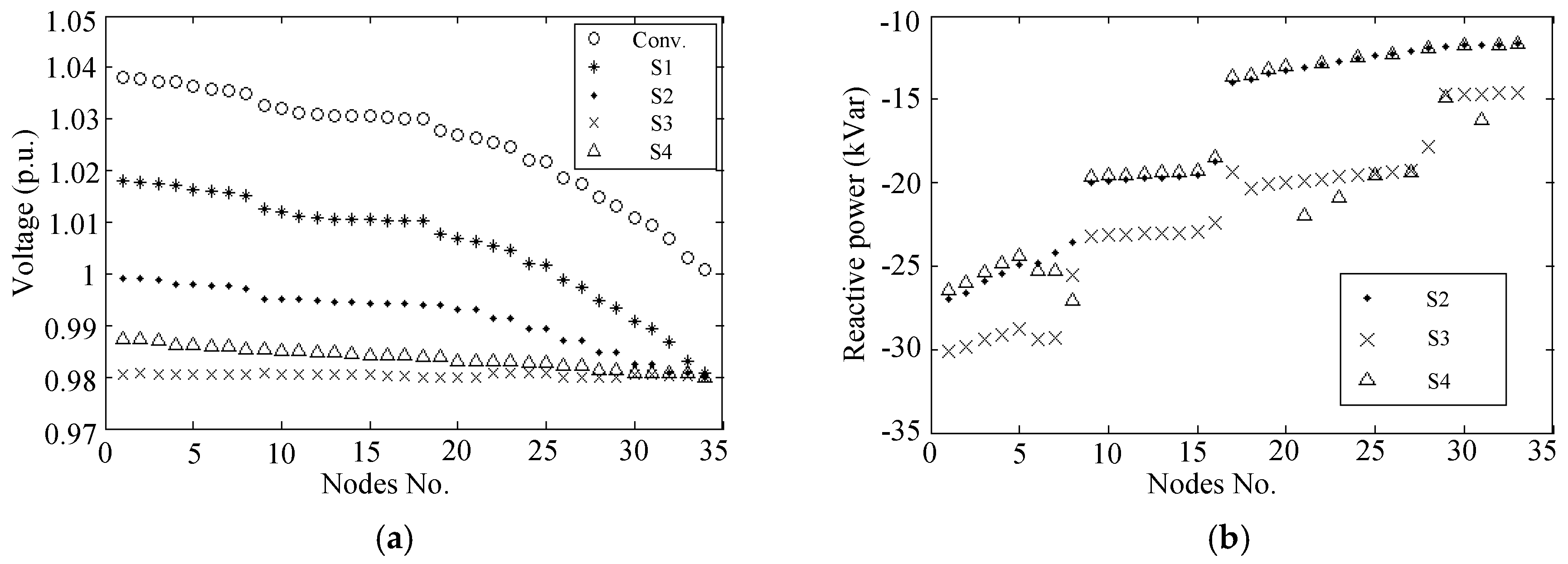
Assuming that each generation unit outputs 60% of its rated power, and the grid voltage is set as 0.98 p.u., the voltage of each node and the corresponding reactive power output are shown in
Figure 7a,b, respectively. Taking into account the wind farm voltage fluctuation requirements and the limitation of the reactive power compensators, control strategy S4 provides the optimized solutions for the reactive power compensations under limited capacity. The node numbers are arranged according to their electrical distances from the PCC point, where the PCC node is No. 34, and the node located the furthest away is No. 1. Though the VSCF turbines can also be applied to compensate for the voltages, the reactive power capacity is always limited. As different relative voltage control strategies require different amounts of reactive power from the turbines, the attached STATCOMs are applied at the turbine-side to avoid the lack of the reactive power capacity in the simulation.
As the conventional control and proposed strategy S1 only regulate the PCC voltage, the reactive power distribution diagram in
Figure 7b elaborates the performance of the rest of the strategies from S2 to S4, which all have the distributed compensators installed at the voltage nodes from No. 1 to No. 34. It is clear that the reactive power of the compensators is effectively decreased while applying the proposed relative voltage control. Thus, in a way, the VSCF turbine can be applied to maintain the terminal voltage, without fear that the required reactive power will exceed its limited reactive power capacity.
The compensated reactive power at the PCC needs −0.79123 Mvar under the conventional method, −0.68672 Mvar under the S1 method, −0.21871 Mvar under the S2 method, −0.16873 Mvar under the S3 method, and −0.2102 Mvar under the S4 method. According to the unit price of the compensators in the market, the average cost for the complete set of reactive power compensation equipment is about 80,000 ¥/Mvar, which also includes the initial costs of the power converters.
Table 1 shows the total amount of reactive power equipment and investment required for different control strategies.
To sum up the different control methods above:
- (1)
For the control of the PCC voltage, it can be maintained at the per-unit value of 1 based on the absolute voltage. The strategy S1 of the relative voltage control sets the PCC reference voltage according to the present grid voltage value. Considering the limited capacity of the wind farm, the required compensation power of S1 is smaller than the conventional method. However, these two methods cannot effectively regulate the global voltage inside the wind farm, due to lack of distributed reactive power compensators. Under such circumstances, the maximum voltage error inside the wind farm under the conventional method is 3.8%.
- (2)
Strategy S2 can compensate for the voltage drop in the box transformers, based on the local observed signals. The distributed reactive power is injected into the PCC, and therefore, the capacity of the PCC compensator can be greatly reduced. However, the voltage drops along the feeder lines are still not compensated for. Under this strategy, the maximum voltage deviation within the wind farm is 1.9%.
- (3)
Strategy S3 can realize the global voltage controllability with compensators installed at all of the key voltage nodes. Therefore, all the nodes inside the wind farm can be maintained as the PCC voltage in per-unit value, which increases the stability of the terminal voltage of the generators, so as to reduce the off-grid accidents. Since the voltage drops along the feeder lines are also compensated for, the total reactive power capacity will increase. With each distributed unit that can compensate for the local relative voltage loss, the reactive power required at the PCC is further reduced compared to strategy S2. Compared to the existing global voltage control strategy, based on upper scheduling, the stability and dynamic response are much improved.
- (4)
Strategy S4 applies the IPFA algorithm to realize the optimized compensation under the reactive power capacity. Because the structure and parameters of the wind farm are relatively fixed, the optimization method can be given in advance. In the simulation, the maximum voltage error can be regulated within 1%, which can also satisfy the optimal reactive power capacity margin.
It can be seen from the parameters in the
appendix that the length of three feeder lines are close to each other, and each line contains three major confluence nodes which are farther apart. Therefore, the voltages are mainly divided into three groups by the confluence section. It is clear that, in the optimization results, the installed compensators were located at the main confluence nodes, to reduce the average errors of the distributed voltages. As the time constant of the voltage variations requests faster reactive power compensations, the proposed relative voltage regulation strategy, based on the local observed information, is superior to the conventional method with respect to the dynamic response and stability.
6. Conclusions
Considering that the increasingly deteriorative voltage dynamic response and stability problems of wind farms, due to the present reactive power compensations, always involve a large data scheduling and transmission delay, this paper proposed a relative voltage coordination method based on the local reactive power compensations. As the total power capacity of the wind farm is far less than the grid, this method only compensates for the local reactive power caused by the active power fluctuations from the wind turbines, which reduces the required reactive power from each compensator compared with the absolute voltage value regulation, and further avoids the possible power oscillation caused by the clipped controllers. Secondly, as the network parameters are pre-known, and the local voltage and current information can be observed locally, the proposed strategy can realize the global voltage control and reactive power allocation without an upper calculation center, as well as provide a faster and more stable dynamic response without long distance intercommunication. Moreover, the optimization algorithm can also be applied in the proposed control, to regulate the maximum voltage error of the wind farm within the requirements of the minimum reactive power capacity. Finally, a simulation example of a wind farm in northern Hebei proved the effectiveness of the proposed voltage coordination control, which improves the dynamic performance of the internal voltage regulation inside the wind farm, as well realizing the local reactive power compensations without remote communication.


