1. Introduction
A power system is always a subject to various small and large disturbances during steady-state operation. System engineers and planners try to design the most reliable power system structure, which is able to cope with all the possible contingencies. However, a minor probability of contingencies does exist when an unpredicted scenario of complex events may lead to power system instability. One of the most dangerous power system instability conditions is angular instability, often referred as asynchronous operation (AO) of generators or an OOS regime. When generated power cannot be successfully delivered to the load (the limited capacity of the TLs, short circuits, insufficient generation, etc.), then, in response to the generation/load imbalance, some parts of the power system generator start to operate asynchronously with the remaining part of the system. The OOS regime cannot be tolerable for a prolonged period of time due to the negative impact it has on the power system equipment and the system integrity. The last resort to avoid possible power system collapse is controlled splitting of the network into several electrically isolated islands. The objective of network splitting is an attempt to preserve the balance within each island. A dedicated protection system should respond to the OOS condition, acting on power network splitting by means of tripping TLs, which interconnect asynchronously rotating parts of the network. All types of OOS protection systems can be divided into [
1]:
Protection of a local type, which uses only locally available measurements for OOS regime detection and decision-making;
Wide-area measurement-based OOS protection, which uses system-wide measurements and assumes centralized decision-making.
OOS protections of a local type are predominantly used worldwide. The reason for that lies partially in a historically conservative approach to power system elements protection when reliability is a paramount. Local protections use a well-established and reliable technology but fail in providing the optimal decision when system-wide disturbances are considered. In turn, a system-wide measurements approach provides excellent observability and optimality in decision-making but still is not used widely for protection duties. Presumably, the reasons for that are reliability (security and dependability) issues. A comprehensive overview of wide-area measurement technology implementation for power system needs was given in [
2]. The most important factor affecting a wide-area protection scheme is the reliability of the supplemented structures; communication channels and synchronization availability [
2]. Equally important is the performance of the protection algorithm; it should be reliable, well-proven, and simple and should provide a good traceability of the processes happening.
This paper proposes a combined approach, for which a wide-area measurements technique and local device-based decision-making are merged by well-proven and reliable communication technology.
The protection system structure, algorithm of operation, and the concept of possible implementation were presented in [
3]. This paper, in respect to [
3], presents the modified algorithm of the protection operation and also provides protection algorithm validation examples using an OOS regime modeling approach.
The rest of the paper is organized as follows. OOS protection theoretical and technical background is presented in
Section 2.
Section 3 reviews a proposed OOS protection structure and a protection operation algorithm is also presented. An OOS regime modeling approach was used to validate the protection operation algorithm, and the results are presented in
Section 4.
Section 5 and
Section 6 present the concept of practical implementation of the proposed protection system using an IEC 61850 communication standard. Finally, the conclusions are drawn in
Section 7.
2. Out-of-Step Protection Background
OOS relaying philosophy and methods are well known and established. The main objectives of the OOS protection system are; detect power system AO at an early stage, take some preventive actions trying to avoid OOS development and, if preventive actions fail to have the desired effect, i.e., the OOS regime is still developing, then OOS protection should split the network into several asynchronously rotating parts. The splitting of the power system is accomplished by means of tripping several TLs, which interconnect asynchronously operating parts of the network [
4,
5]. Controlled splitting should take place at predefined locations with the expectation that generation/load balance within each island could be achieved by means of local automation systems action.
At least several online OOS detection methods and algorithms are known and are used with more or less success [
4,
5]:
Distance algorithm-based methods;
The Ucosφ algorithm;
Energy function-based method;
Angle control-based methods.
Not all methods find their practical implementation, but distance algorithm-based and angle control-based methods are widely used. Distance algorithm-based OOS protection is typically incorporated within TL distance protection terminals and monitors the way the impedance trajectory crosses the protection zone [
6]. The main drawback of the method is that impedance trajectory does not necessarily cross the protection zone of the particular protection terminal in case of an OOS regime. Thus, the preferable network splitting place and the response of the particular protection terminal can hardly be coordinated for all possible OOS regime scenarios, which may lead to the uncontrolled islanding of the network.
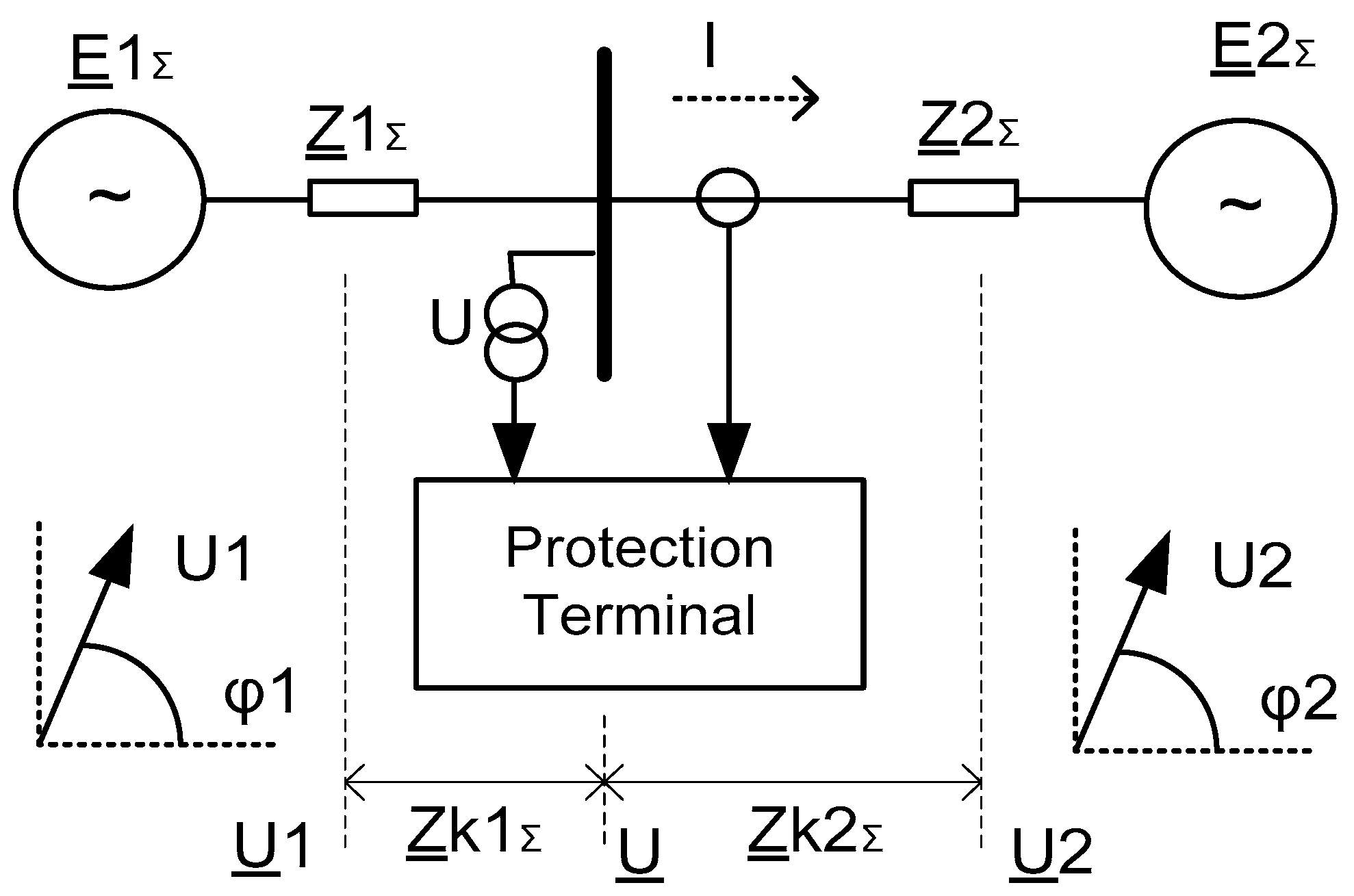
The angle control-based method relies on the detection of the angle difference between two voltage phasors, measured at critical network locations. OOS protection operates when the angle difference exceeds the maximum allowed value. The Latvian Power system network and the neighboring networks of Estonia and Lithuania use angle control-based OOS protection of the local type described in [
7,
8,
9]. Protection uses only local measurements (bus voltage and current through the line of interest), and the entire network should be represented with a two-machine equivalent. The protection models voltage phasors
and
(1) of equivalent generation sources for a two-machine network (
Figure 1) monitor the angle difference δ and the rate of angle difference change dδ/d
t according to Formulas (2) and (3). Terminal settings
C1,
C2,
C3, and
C4 define the protection operation conditions. The effectiveness of angle control-based protection is highly dependent on the accuracy of the voltage phasor modeling. The main drawback of the protection is its inability to adapt in real-time protection equivalent impedances, setting
and
to the current network configuration and the regime of the power system. As a result, the protection settings should be calculated, taking into account the worst case scenario of network configuration and regime. Thus, compromised settings may deteriorate the performance of the protection.
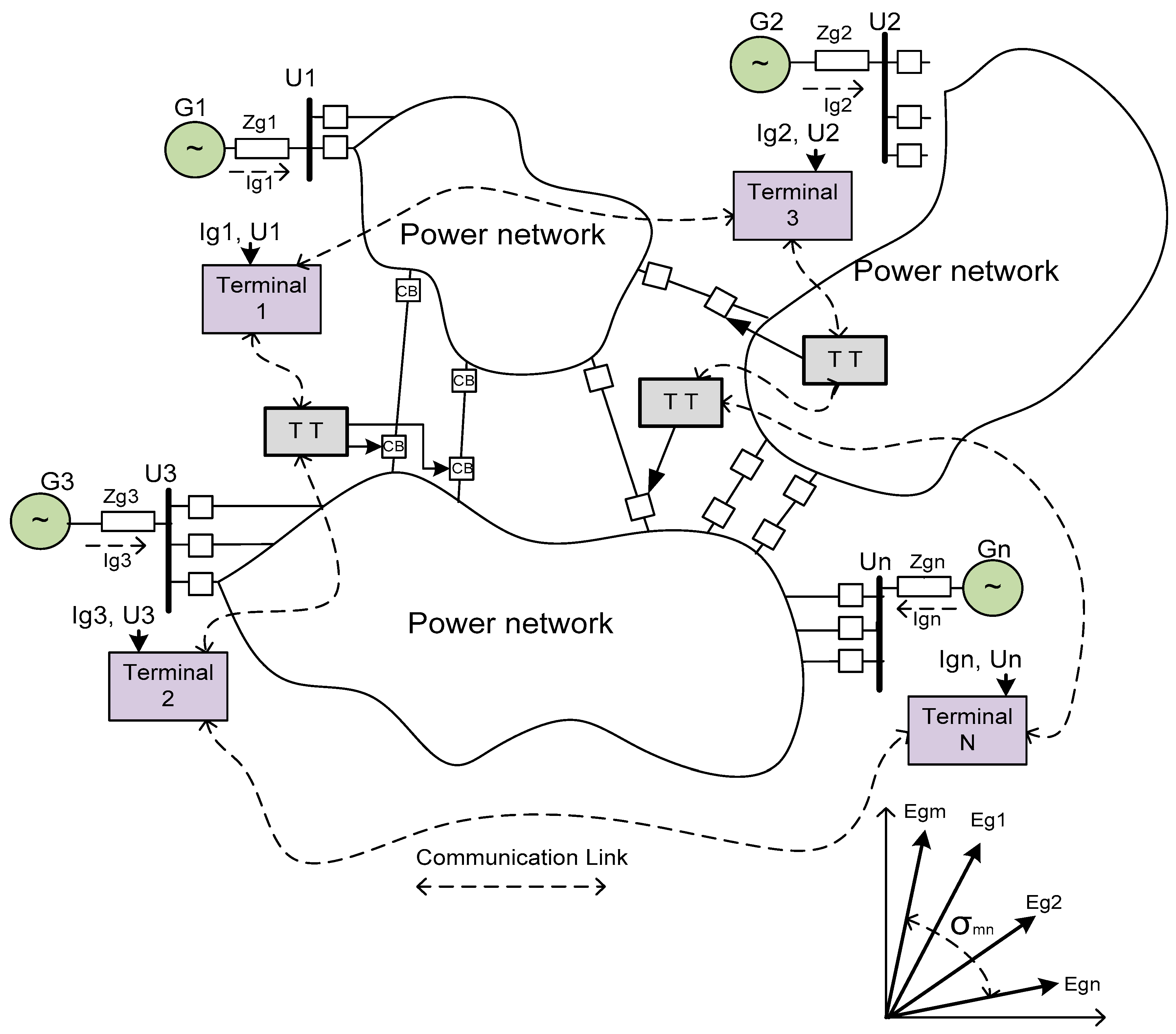
Another angle control-based approach, often referred to as Wide-Area Protection Systems [
1,
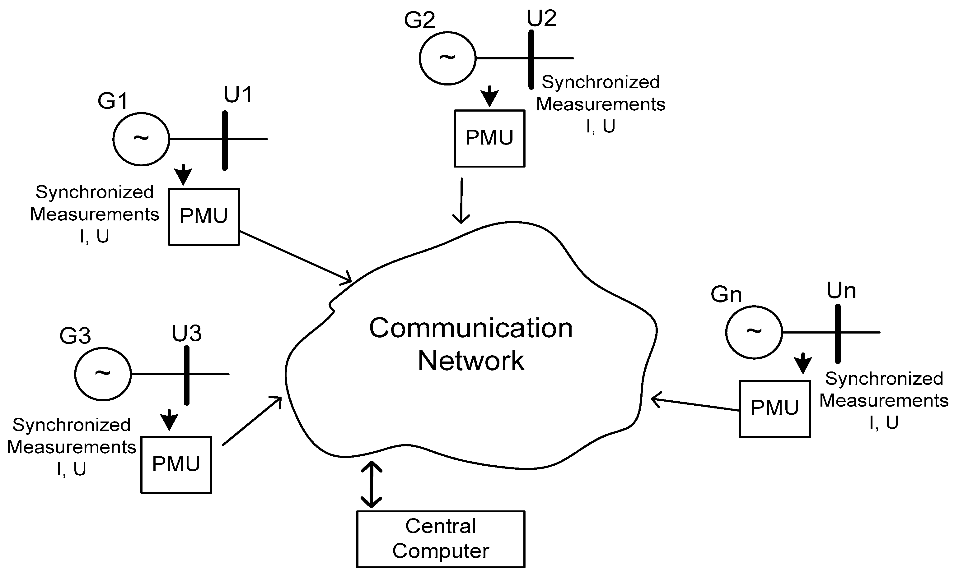
10], uses system-wide measurements for OOS regime assessment. The basis of such a system is the phasor measurement unit (PMU) (
Figure 2), which samples local currents and voltages and transmits the calculated phasors to the main control center, where information is further processed and a decision is made.
All measurements are synchronized and time-stamped. Thus, the information about system-wide angles can be easily derived from PMU’s phasor data and system-wide angle control can be established. The prerequisites for system operation are having a sufficient number of PMUs installed, a fast and reliable communication network, measurements synchronization availability, and a real time operating decision-making computer. The PMU sampling rate is high enough to calculate phasors with very high precision, but the phasor data transmission rate is standardized to 20–60 frames per second [
10]. For a centralized decision-making system, the PMU’s data transmission rate is of importance. OOS protection should be able to segregate an OOS regime, which is a balanced regime, from all other transients/unbalanced regimes that may appear during contingency. Considering this, a PMU-based solution may be limited in functionality because all fast transients should also be captured to ensure a protection secured state.
3. Proposed OOS Protection Structure
The proposed OOS protection system combines both principles; wide-area measurement technology and local device-based decision-making. The system consists of several protection terminals (
Figure 3), with each of them measuring generation sources’ currents and voltages at the power plant level [
9]. The protection system structure is similar to the PMU-based approach, except that proposed structure is able to operate in protection-like real time (>250 samples per second). It is supposed that dedicated communication links will be used for data exchange between protection terminals (similar to that used for line current differential protection duties). This approach helps in avoiding possible uncertainties in data processing, which may arise as a result of fast transients and unbalanced states of the network.
Each terminal models equivalent generator electromotive forces’ (emf) vectors according to Formula (4). It is supposed that
is equivalent to the emf of the power plant, which in turn may consist of several generator units.
where
is the voltage at the station bus;
is the total current of the generation source; and
is the equivalent impedance of the generation source.
The measurements of all the terminals (currents and voltages) are synchronized and time-stamped by means of a GPS-disciplined clock. The terminals exchange modeled emf phasors in real time and each terminal continuously checks the balanced regime of the network by testing conditions (5) and ignores the measurements for all the unbalanced regimes. The locally detected network status (balanced/unbalanced) is also transmitted to all terminals along with the emf phasors.
where
and
are the voltage and current negative sequence components and
C5 and
C6 are the terminal settings.
Upon completion of the information exchange cycle, the emf vectors of all the generation sources are available for each terminal, and also the network condition is known. The terminals calculate the angle difference δ and the rate of change dδ/dt for each pair of emf vectors and continuously check the fulfillment of (3). An OOS regime is recognized if the angular difference δ between any pair of generators reaches the maximally allowed value C2 and conditions (3) and (5) are satisfied.
At the next stage, the terminals should choose the appropriate cut set; the TLs that should be tripped to split the power network into several islands.
Finding the optimal islanding solution is a multi-objective task and the two main objectives are:
- (1)
The load/generation imbalance after islanding should be minimized and local resources should be able to support frequency and voltage profiles within acceptable margins for each island.
- (2)
Power TLs and associated facilities within each island should not be overloaded.
The dynamical behavior of the generators after the contingency may be presented as a set of fast and slow modes, which, respectively, reflect the interactions of tightly coupled generators within some areas and loosely coupled generation sources between areas. It is shown in [
11] that network splitting can be based on the detection of the weak link between groups of slowly coherent generators. Then, the splitting decision should be taken considering two additional constraints:
Each island should contain tightly coupled coherent machines, which operate synchronously.
The formed island should be capable of a black start in the case that the first or the second objective is not satisfied.
Various algorithms have been proposed to find the optimal splitting boundary [
12,
13,
14,
15]. The majority of methods can be classified depending on the objective function used; (1) minimal power imbalance or (2) minimal power flow disruption.
Finding the optimal islanding solution, which takes into account both the objective functions and all the associated constraints, is an extremely complex task, which could hardly be solved within a real-time operating OOS protection system. From another point of view, several of the afore-referenced methods can be successfully implemented offline, thus providing us with the most probable islanding scenarios and possible optimal cut sets for each scenario. For the protection system under consideration, it is supposed that the possible splitting scenarios should be determined offline, using the network regimes modeling approach. Modeled OOS scenarios should consider several topological configurations and associated power flows that are typical for a given network. The objective is to determine potentially feasible groups of coherent machines for each OOS scenario. Then a list of possible groups of coherent generators along with presumed TLs cut sets for each scenario should be assigned to the settings of the OOS protection terminals. The task of protection terminals is the online identification of groups of coherent generators and the selection of an appropriate splitting decision from a predefined list, depending on the groups formed.
Various methods for generators coherency identification have been reported in the literature. A model-based approach, which relies on an eigenvalue analysis of the system is proposed in [
16,
17]. Several measurement-based methods were suggested; improved Laplasian eigenmap algorithm used in [
18], Fourier analysis was implemented in [
19] to find the spectrum of speed deviation and then phase of the dominant frequency component estimated, Hilbert-Huang transformation is used in [
20] to find the instantaneous phase difference of the dominant mode of oscillations, and the Pearson correlation coefficient –based technique is proposed in [
21].
Groups of coherent generators can be identified online according to the methodology described in [
21]. The method is based on generators angle control. The correlation coefficient
CRij of generators
i and
j is calculated according to Formula (6):
where
and
stand for the generators’ emf vector angles and
is the average of the
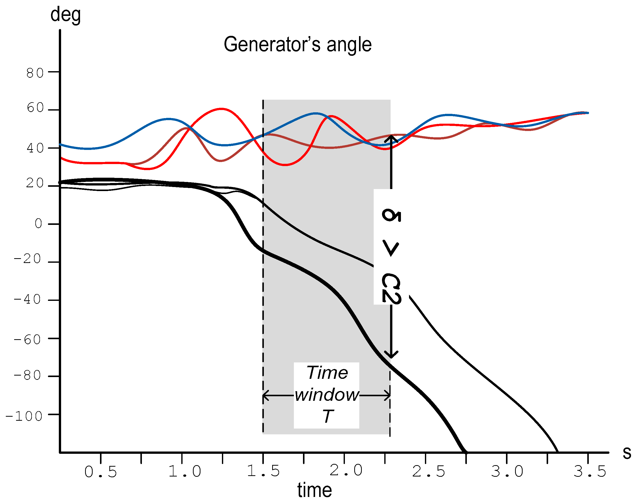
N samples. The correlation coefficients range is from −1 (the strongest negative correlation) to +1 (the strongest positive correlation). The number of samples used for the correlation coefficient calculations is defined with time window
T (
Figure 4), which is the appropriate setting of the terminal.
Time window T is a sliding window (data buffer) in which the oldest sample is discarded as soon as new sample becomes available.
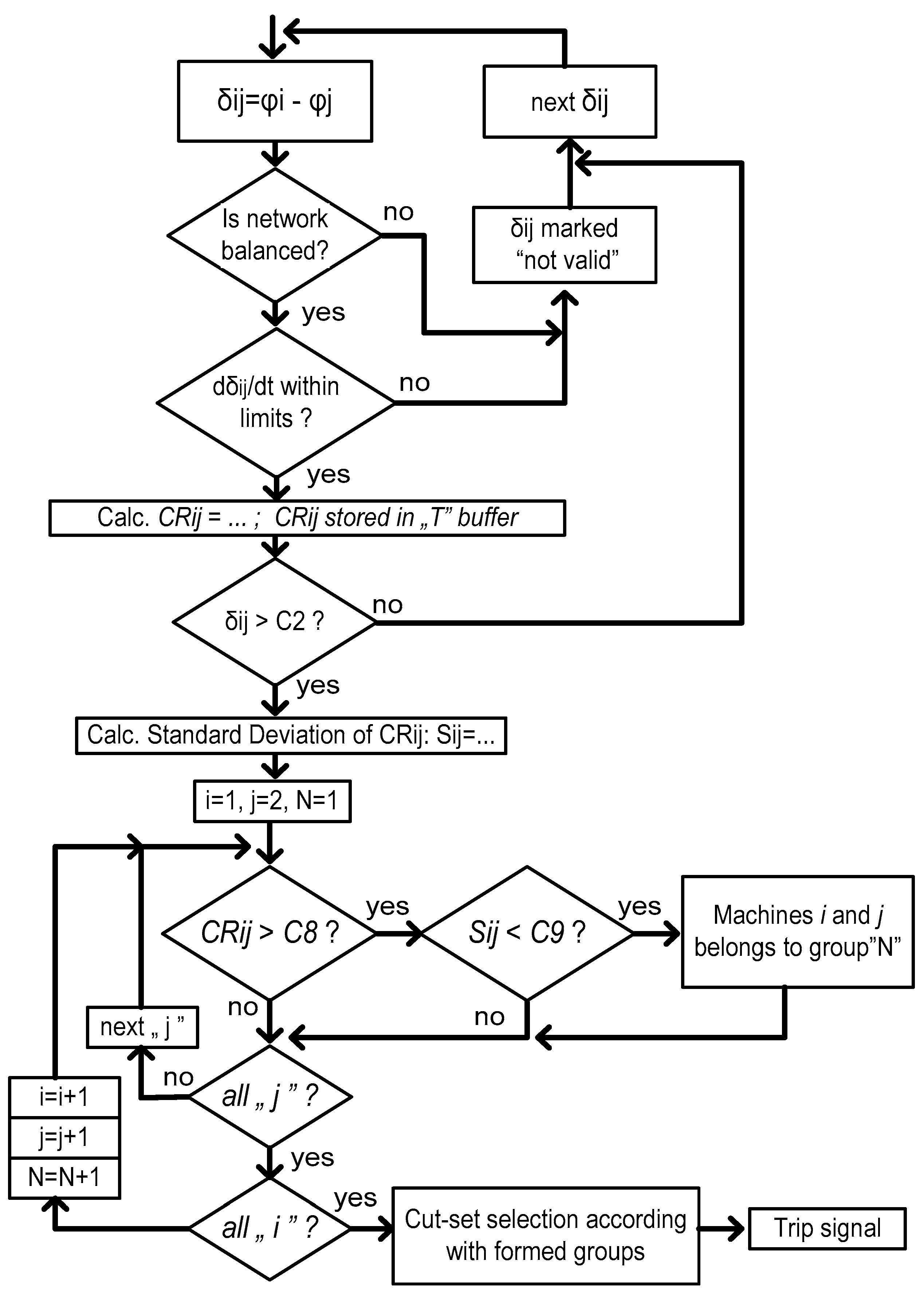
The protection terminal operation flowchart presented in
Figure 5. To discriminate between an OOS regime and all other unbalanced regimes, angle measurements will obtain the valid status and will be further processed only in case the network is balanced and the rate of change of the angle difference is acceptable. The coherent generators groups’ determination procedure starts when the angle difference between any pair of generators exceeds the maximally allowed limit
C2 (
Figure 4).
Two conditions indicate the generators coherency; the generators pair correlation coefficient value
CRij is close to its maximum value (1.0) and the correlation coefficient does not change significantly during observation. The groups of coherent generators are formed by comparing the value of the correlation coefficients with setting
C8 and comparing the standard deviation of the correlation coefficient
Sij (7) with setting
C9.
where
is the average of the
N calculated correlation coefficients.
After the generator grouping procedure is finished, the terminal searches for a suitable splitting decision within a predefined list of available cut-sets. A trip signal can be generated locally, or a trip command can be transmitted to the remote terminals (TT) by means of the communication network (
Figure 3).
4. OOS Protection Algorithm Validation
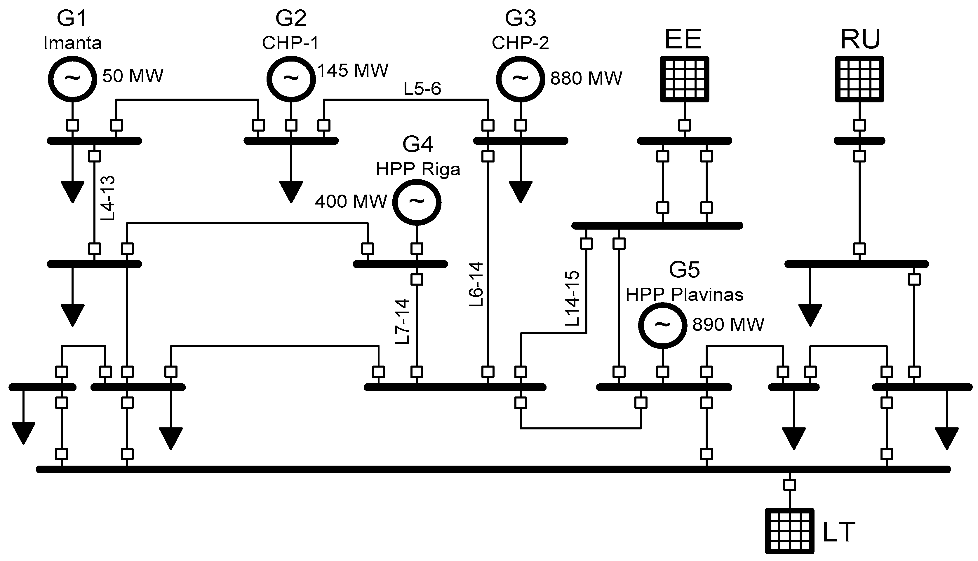
Electrical Power System Analysis and Operation software “ETAP” and the Latvian power system network model were used to validate the algorithm of the proposed OOS protection. A simplified 330 kV Latvian network structure with five major generation sources
G1
…G5 is presented on
Figure 6. The Latvian power system has interconnections with the Estonian (
EE), Lithuanian (
LT), and Russian (
RU) power networks.
The purpose of the network regime modeling was the evaluation of the generation sources behavior and the adequacy of the OOS protection algorithm response for several OOS regime scenarios. It is supposed that the OOS protection structure presented on
Figure 3 is used with five protection terminals installed at each power plant (
G1,
G2,
G3,
G4,
G5), with terminals exchanging in real-time with generators’ emf vectors and deriving the angle difference for each pair of machines. Coherent generators groups’ identification time window length
T was set to 1 s for all scenarios, which corresponds to 50 data samples. The maximally allowed angle difference between any pair of generators’ emf (
C2) was set to 360 electrical degree. Generator grouping settings
C8 and
C9 were set accordingly to
C8 = 0.8 and
C9 = 0.1.
OOS regimes were created as a result of short circuit, applied to one of the critical TL, followed by tripping of the faulted line circuit breakers. The results of OOS regime modeling for several scenarios are shown on
Figure 7,
Figure 8,
Figure 9,
Figure 10 and
Figure 11.
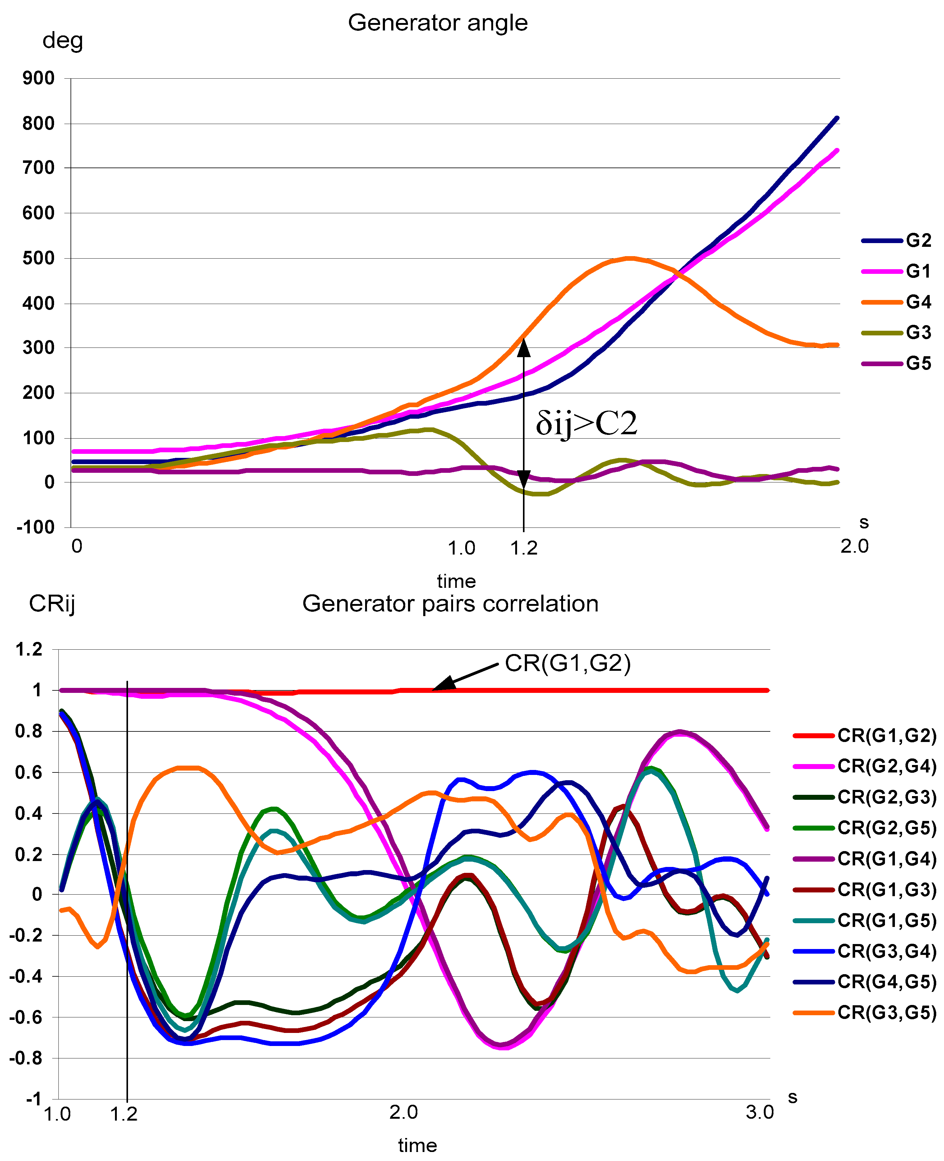
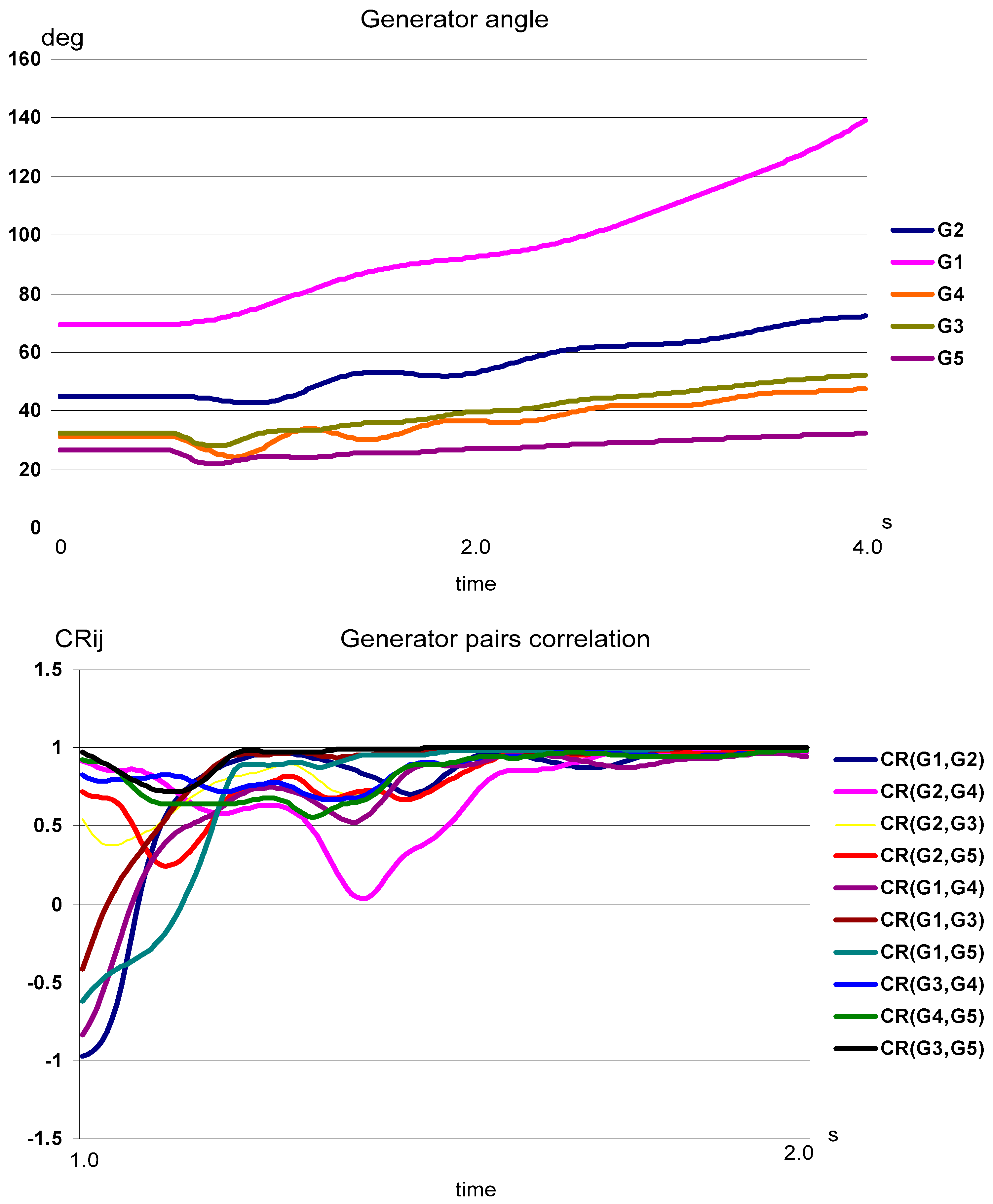
Each scenario is presented with two charts; the first chart shows the generators angle variation after contingency was applied and the next chart shows how the correlation coefficient, calculated for one second sliding window, changes in time. The correlation coefficient for the pre-fault regime may have a meaningless value (the denominator in (6) may have zero value); that is why correlation coefficients charts start from the 1 s time point.
The first scenario is a short circuit applied to line
L14–15 (
Figure 6). The purpose of this scenario was to create the condition in which all machines of the Latvian power system swing together relative to neighbors’ networks (Estonian and Lithuanian). While the maximal angle setting
C2 was not reached in this case (
Figure 7), the correlation coefficients chart shows that
CRij (6) for all pairs of generators asymptotically approaches to 1 at time 2 s. This indicates that all generators will form one large group and there is no AO between Latvian system generators. In this case, islanding should be done by tripping the lines which interconnect the Latvian network and the
EE and
LT networks.
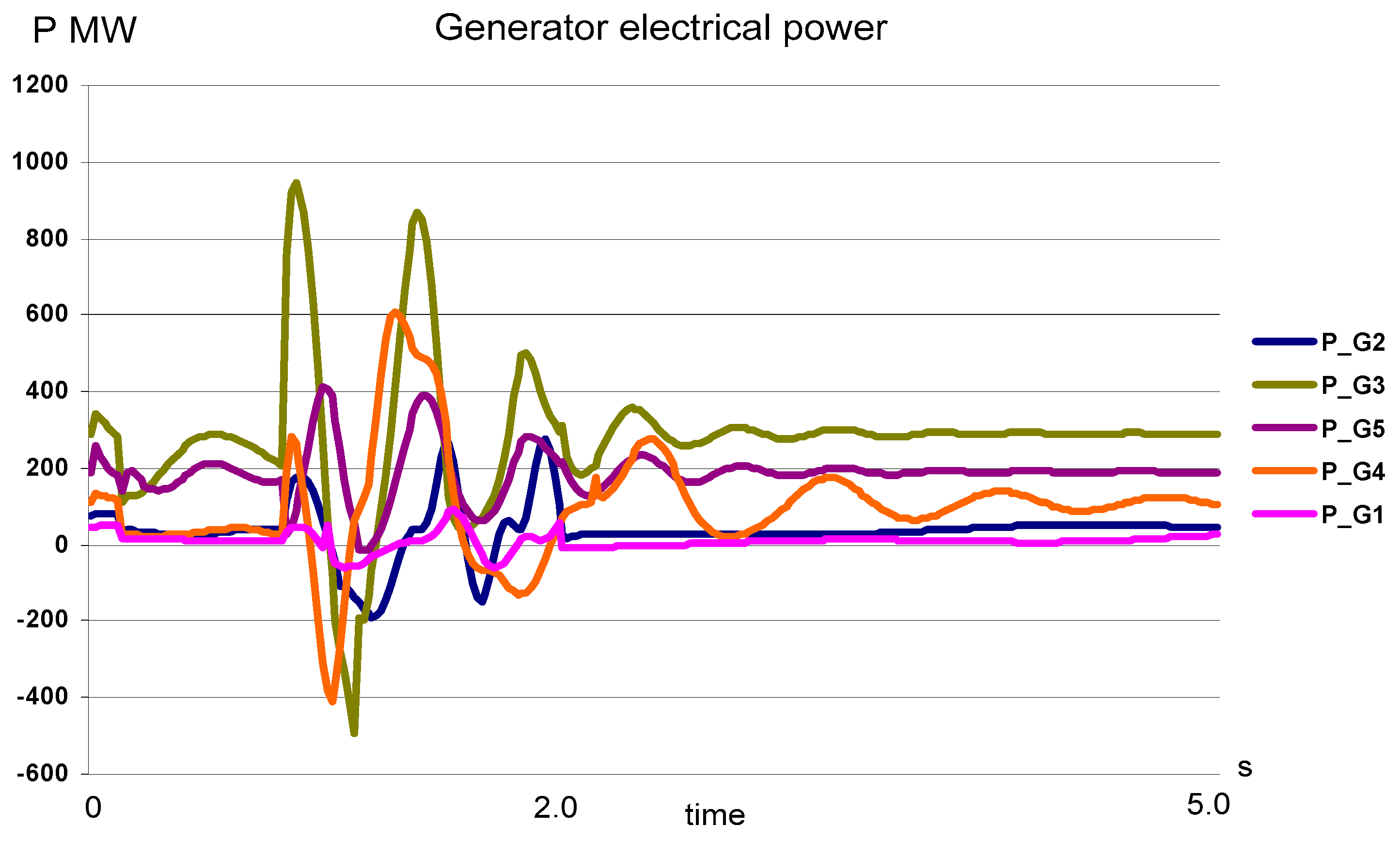
The second scenario is a short circuit applied to line
L7–14 (
Figure 6). Power transfer from
EE side was intentionally limited for this scenario (one of the two parallel lines from
EE network side was not in operation). Generators
G1,
G2 and
G4 swing together in respect to other machines and
G1 and
G2, finally running out of synchronism (
Figure 8). The maximal angle setting value was reached at approximately 1.2 s. The correlation coefficient of generator pairs
G1,
G2 and
G4 has the highest value (close to 1.0), indicating that generators
G1,
G2 and
G4 form the group that is asynchronously operating in respect to other machines. Generator
G4 finally settles down after the first complete rotation circle. This fact is observed in the correlation coefficients chart, where
CR(G1,
G4
) and
CR(G2,
G4
) diverge from 1, starting from 1.5 s. The correlation coefficient
CR(G1,
G2
) remains almost constant with standard deviation not exceeding
S12 = 0.005, while the standard deviation of the correlation coefficients for all the remaining pairs exceeds the C9 threshold. In this case, the decision is taken at time 2.0 s; then only generators
G1 and
G2 constitute the asynchronously operating group.
The well-damped behavior of the remaining machines is observed after splitting the network by means of tripping lines
L5–6 and
L4–13 (
Figure 9).
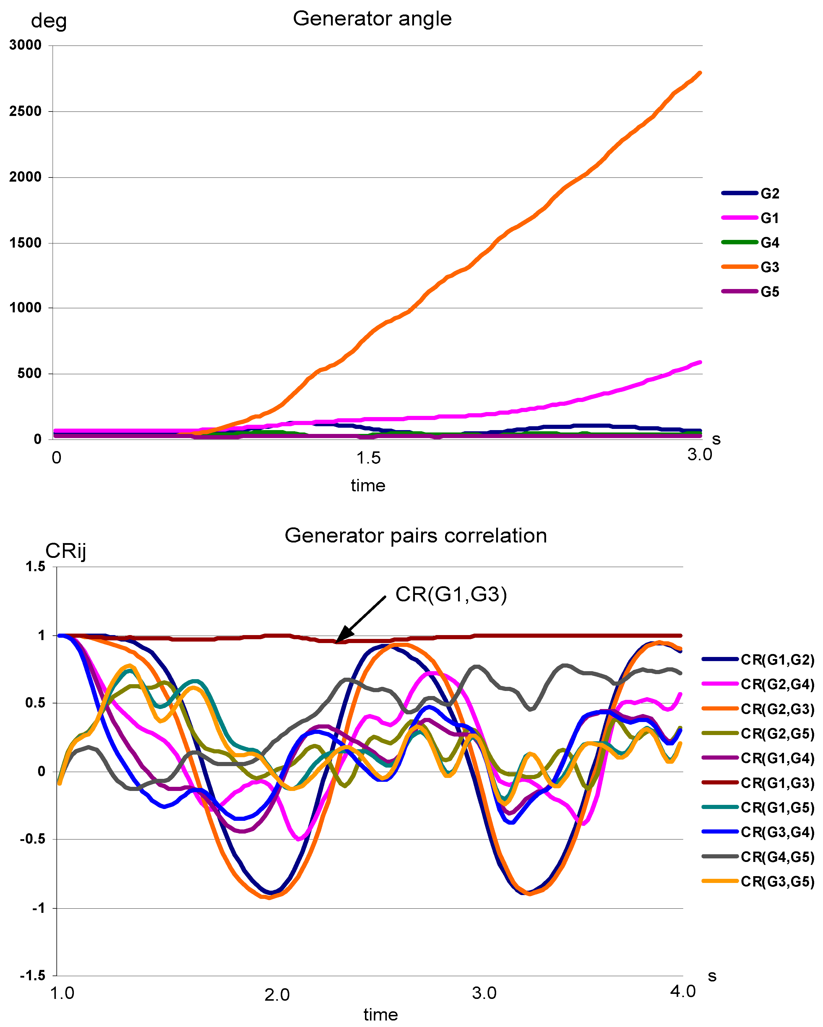
In the third scenario, the short circuit was applied to line
L6–14 (
Figure 6). Two generators,
G3 and
G1, are running out of synchronism (
Figure 10). The correlation coefficient
CR(G1,
G3
) is close to 1.0 and remains almost constant (standard deviation of
CR(G1,
G3
) do not exceed
S12 = 0.02), while the correlation coefficients of all other pairs significantly diverge, starting from 1.3 s. As in the previous case, the reliable grouping of the generators can be done after the angle difference reaches
C2 setting (approximately at time 1.5 s).
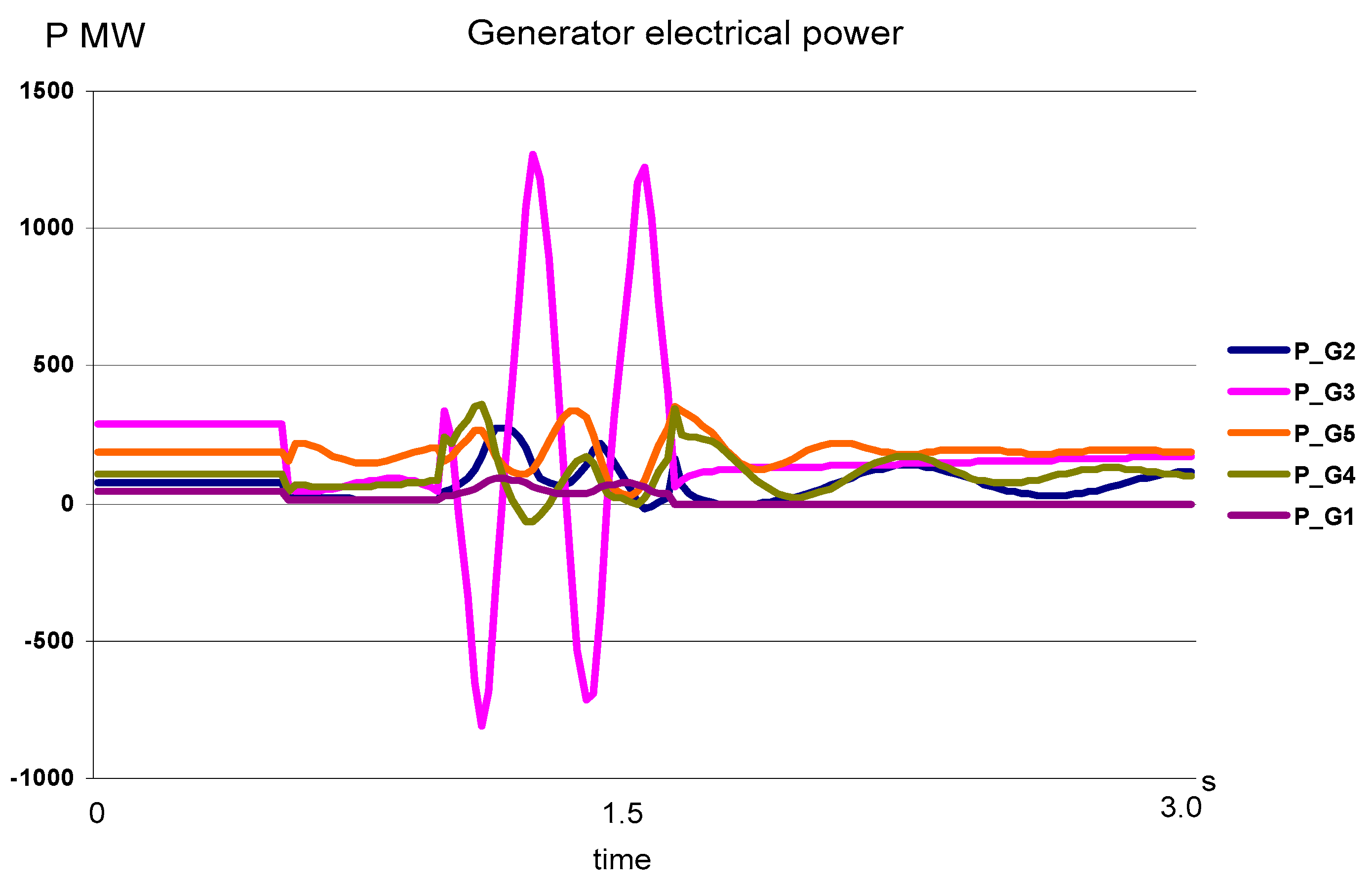
Despite the fact that
G1 and
G3 both operate asynchronously in respect to the remaining network, the only suitable splitting decision is line
L5
–6 tripping, which disconnects the
G3 generator only. In this case, generator
G1 needs to be shut down separately. The result of such splitting at time 1.8 s is presented in
Figure 11.
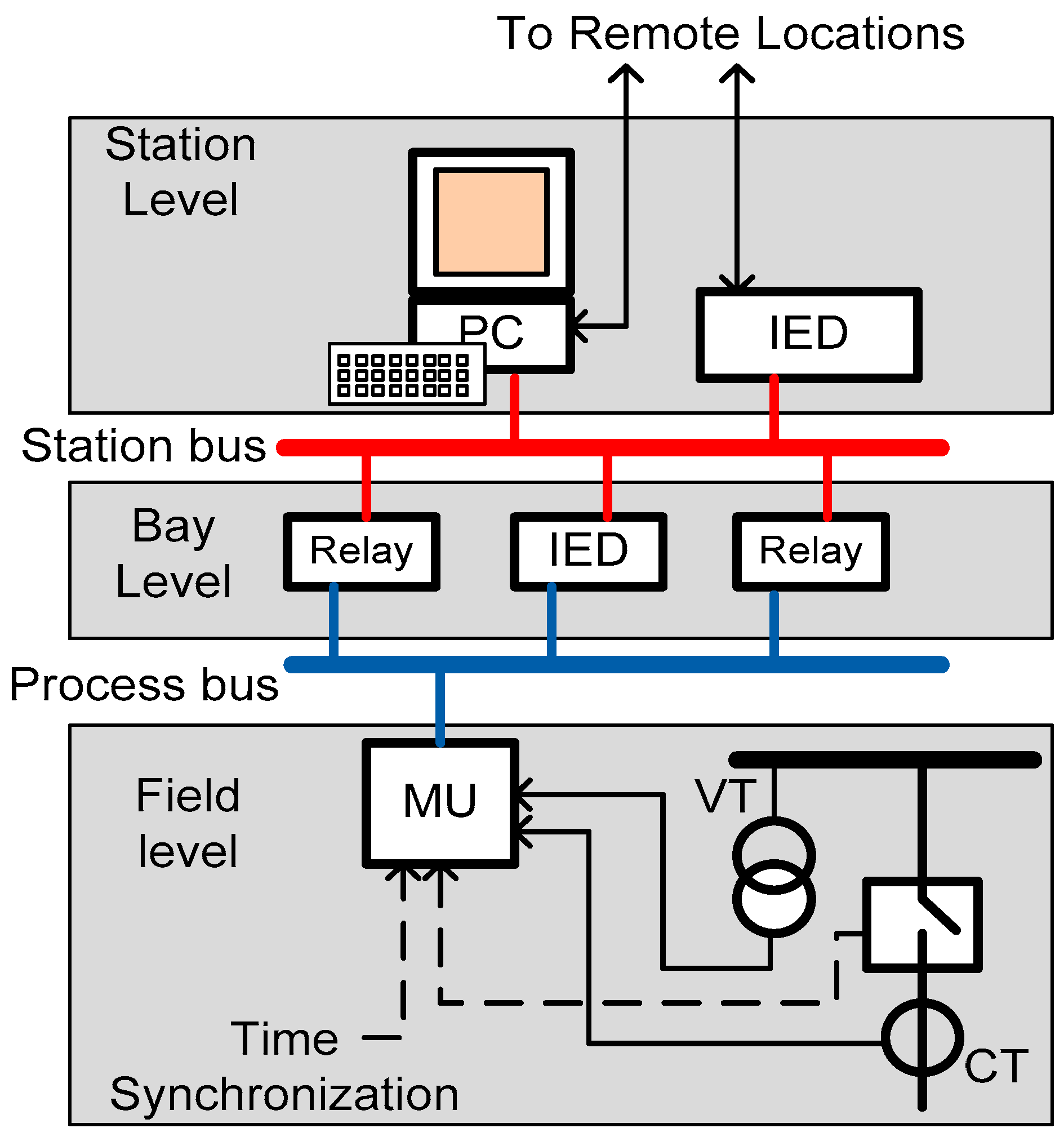
6. IEC 61850 Communication-Based OOS Protection System
The IEC 61850 communication standard-based implementation can noticeably improve the proposed OOS protection system design in terms of complexity reduction and hardware minimization; also, protection system functionality can be easily expanded in the future.
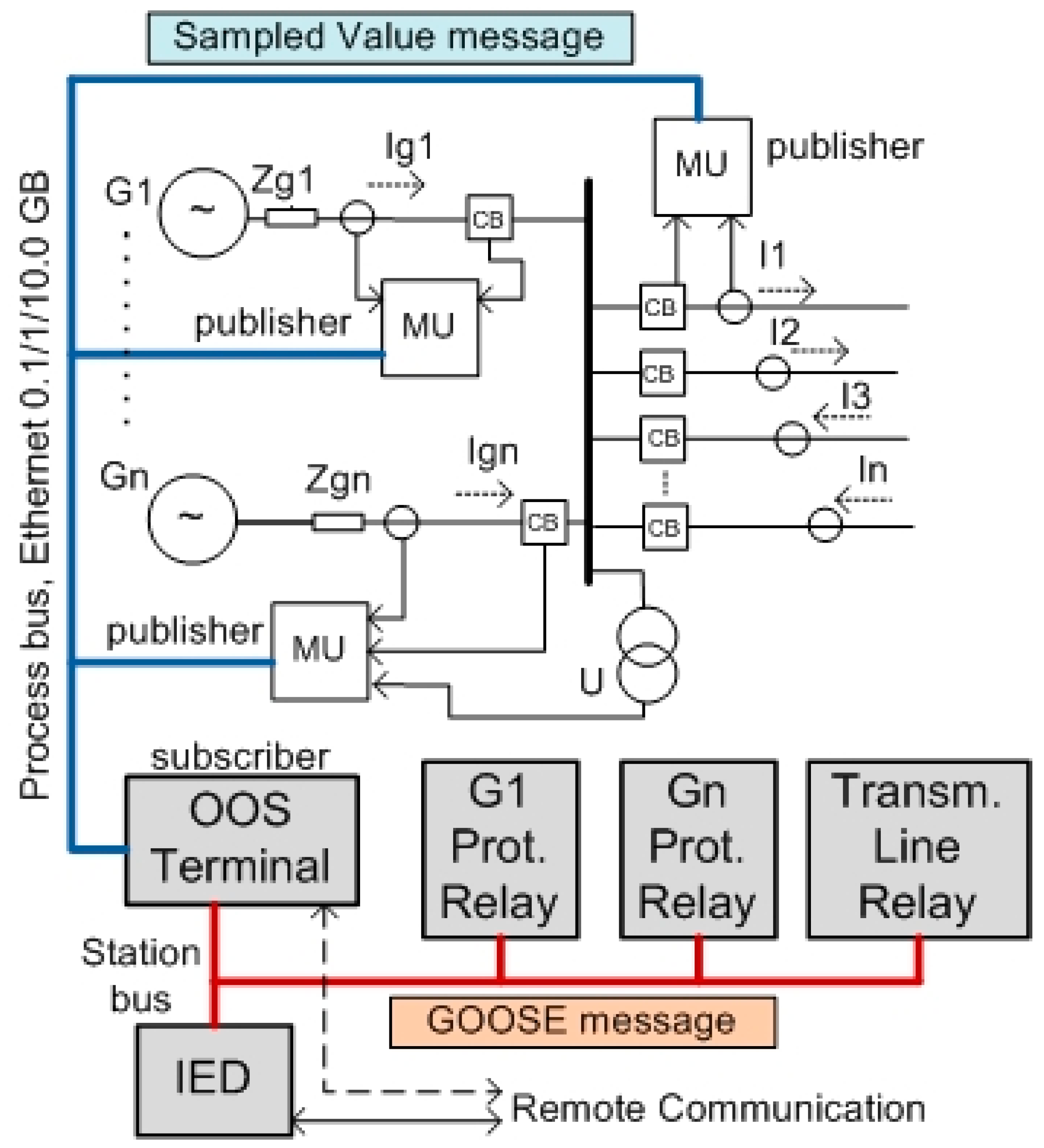
The problem of analogue and status signals hardwiring for several generators of the power plant can be solved by implementing the SV communication technique within the power station process bus (
Figure 13). Here, the OOS protection terminal controls all power station generators by means of subscribing to SV data from each generator’s MUs.
Thus, the terminal is provided with all the necessary information (generators’ currents, bus voltages, and generators’ status information). Additionally, status information (on/off) for the outgoing transmission lines’ circuit breakers (CBs) and transmission lines’ currents values I1, I2, …, In is also available for a OOS terminal as a subscriber. This information can be used for network topology recognition and may also help to coordinate the power system splitting place, considering the existing network configuration. At the station level, the OOS terminal may benefit from obtaining information from protection relays and various IEDs by means of subscribing to a GOOSE message from relays of interest. The main point here is the availability of information about short circuits and other unbalanced conditions of the network. The OOS terminal does not need any more to trace the unbalanced regimes of the network because this information is available from the neighboring relays.
As shown in
Figure 3, the proposed OOS protection system uses a dedicated communication link between terminals (similar to the one that the line current differential protections are using). Reliable inter-station communication is a critical part of the proposed OOS protection system. The present scope of the IEC 61850 standard is limited to data exchange within the substation [
23]. Some attempts are made to adapt the existing IEC 61850 communication services and models to wide-area communications structures [
25]. The main problem here is that the wide-area communication bandwidth between substations is limited (typically 2 Mbit/s), which is far less than the 100 Mbit/s Ethernet bandwidth between IEDs in the substation. At the same time, it is supposed that the amount of information OOS terminals exchange in real time will not overload communication network capabilities (in contrast with line current differential protection, OOS protection data can be transmitted at a lower rate because of the slower nature of the AO processes).
The IEC 61850 GOOSE technique cannot be used directly in this case because GOOSE is an event-driven message. The SV messages specified in IEC 61850-9-2 could offer a solution when extended to inter-station information exchange [
26]. Inter-station communication and communication between substations and the control center are covered by IEC61850-90-1 and the 90-2 section of the standard (some parts are under development). The IEC/TR 61850-90-1:2010(E) document [
27] provides a comprehensive overview on the different aspects that need to be considered while using IEC 61850 for information exchange between substations.

