1. Introduction
A new era of high-speed flywheel energy storage (FES) started with the advent of carbon composite flywheels, a technology that has become more viable due to a trend of decreasing costs of power electronics, position sensors (for magnetic bearings) and microprocessors [
1]. The commercial potential for FES systems has recently gained attention in various applications. In racing sports, an FES powered the winning car of the legendary Le Mans race for several years. Flywheels have been mounted on inner city hybrid buses to increase fuel efficiency. The technology has also been proven to enable the use of intermittent renewable energy sources, for example by stabilizing the electric grid at remote wind farms, allowing for better utilization of transmission lines. Improving the capacity factor of power lines is important in all applications when the cost of the transmission itself is a significant cost of the installation, such as for offshore wind power or wave power parks. FESs are used to provide fast regulation power for maintaining the grid frequency, decreasing the use of inefficient coal plants with low ramp rates for the task. On a distribution grid and end customer level, FESs are used to improve power quality for industries and data centers [
1].
Modern, electrified flywheels are mainly composed of steel, aluminum, titanium, carbon and glass fiber composites, which are all readily available in bulk volumes. Energy is stored when the electric motor/generator accelerates the flywheel, and energy is released when the electric machine acts as a generator and slows down the flywheel. Flywheels compete with storage technologies, such as batteries and electrolytically double-layered capacitors (EDLCs, popularly known as supercapacitors) in applications that require a large number of charge-discharge cycles with high specific power. Flywheels excel when compared against batteries in terms of specific power and cycling fatigue. Comparing costs is harder however, since the latter is mass-produced, but the former is not. An estimate can be computed based on the knowledge that for rotating electrical machines, raw materials comprise about 60%–70% of the cost [
2]. GKN Hybrid Power (Worcestershire, UK) reported that the raw material cost of a standard internal combustion engine is about 685
, compared to their 30 kW/111 Wh flywheel for automotive applications, which costs about 723
[
3]. The resulting cost would then be about 1100
, or 10,000 USD/kWh, which is about 30-times more expensive than Li-ion batteries [
4]. On the other side, a high-performance Li-ion battery can only use 3% of its capacity to withstand
charge-discharge cycles (which FESs and EDLCs are typically rated for), during moderate discharge rates (≤1C) [
5]. It should also be noted, however, that a flywheel excels at delivering power while retaining a good cycle life. A battery topology with a system specific energy of
(including cooling system, etc.) with a weight of
would match the GKN flywheel (in terms of energy capacity) mentioned above, not taking into account cycling properties. Assuming a requirement of
cycles, the battery system weight would be increased to 20
, and with a discharge rate of
, the maximum power is then only 4
. To meet the power requirements combined with cycling properties, the system weight would have to be increased to 150
, which is 10-times heavier than a modern flywheel system [
1]. Li-ion batteries can be and are currently used in F1 racing at higher power levels, but the battery life becomes very limited.
The specific energy of state-of-the-art automotive FESs (GKN Hybrid Porsche GT3R Flywheel [
6]) is 2.7-times larger than state-of-the-art automotive EDLCs (Maxwell 125V Heavy Transportation Module [
7]), while retaining a specific power 1.8-times larger [
1]. However, FESs are considered to be systems of high complexity, when compared to batteries and supercapacitors. Increasing the specific energy of FESs is important since more end applications become feasible technically and viable economically.
Optimizing Specific Energy
The specific energy
e grows quadratically with radius
r from a fixed rotational axis, as can be seen by inspecting the kinetic energy
E in a rotating body per unit mass
m (with a rotational velocity of
ω):
where the moment of inertia around a fixed axis
J is expanded into its integral definition. The formula essentially states the three ways to optimize for specific energy:
The advent of carbon composites has greatly progressed flywheel development in terms of the first two bullet points above. This paper aims to provide progress in the field with regards to the third option by examining an electric machine with properties suitable for hollow cylinder flywheels.
The paper is divided into three parts: Firstly, hollow cylinder flywheels are introduced, and a theoretical rotor design is presented. Secondly, a switched reluctance machine (SRM) for the aforementioned rotor is presented with measurements and simulations. Thirdly, simulations based on the above measurements are used to compare the SRM with other high-speed machines.
2. Integrated Hollow Flywheels
The connection of a composite flywheel rim to a shaft is an issue well addressed in the technical literature [
8,
9,
10,
11,
12,
13,
14,
15,
16,
17,
18,
19,
20,
21,
22,
23,
24]. The most common class of solutions can be denoted strain-matching and can be traced far back before the unidirectionally-wound composite flywheel era [
13] where the spokes or hub are made of materials and/or shapes that strain in a similar fashion as the rim when exposed to centrifugal forces. Both metallic [
14,
15,
16] and composite [
18,
19] solutions exist. Another category is the conical hubs, where a conical metal interface yields the elastic properties needed to compensate for the rim expansion [
9,
10,
11]. Composite solutions also exist [
12,
22]. A less common category is the flexible rim in which stiff composite spokes holding an elliptical rim at standstill will deform the rim into a circle at nominal strain and speed [
19,
20]. Other interesting solutions include: having flexible composite spokes in which the rim and hub are connected with continuous fibers [
23]; or having a stiff metal hub connect to a composite rim with a high-strain interface made of PVC, nylon or brass [
24].
Recently, flywheels with no shaft or spokes have begun to surface. Instead, the electromagnetic actuators (electric machine and magnetic bearings) reside on the inside of a composite rim. These hollow rotor solutions have been developed as a way to increase rotor specific energy and, thus, decrease material usage and decrease cost [
21,
25], where an industrial manufacturer claims a potential for an 8× decrease in cost [
26,
27]. The decreasing cost of magnetic bearings (in terms of sensors, feedback electronics and power electronics) has made the hollow cylinder technology increasingly feasible. However, a shaft-less design demands more in terms of material strength for the electromagnetically-active parts used for accelerating and suspending the rotor, since these must be placed closer to the rim where the centrifugal forces are larger. Hollow flywheels also face heating issues, since the whole rotor must be enclosed in low pressure due to high speeds, limiting the natural heat transport from the rotor to black-body radiation.
With maximal rim speeds in excess of one km per second [
28], a relatively thin rimmed hollow rotor implies high relative velocities also on the inside of the rotating cylindrical shell. This in turn implies that the mechanical power transmission and mechanical bearings commonly used [
1] are infeasible, suggesting the use of magnetic bearings, which have excellent high-relative speed characteristics [
8,
29].
Below, we will analyze the strain-problem on the inside of a hollow composite rim, as well as show that the radial size of electromagnetically-active steel mounted on the inside of the composite rim is a major limiting factor to ultimate specific energy.
Note that the analysis below is not complete, since a practical design will always have a lower capacity than as defined by the specific energy at breaking. For example, in mass-production (especially in larger machines), it can be more cost effective to increase the rotor safety factor instead of increasing quality requirements for the carbon composite materials. Depending on the end application, the containment itself can impose limits on maximum realistic speed. In automotive applications, there is a trade off between rotor maximal speed and containment weight/strength.
Below, we derive plane stress equations for a long hollow cylinder flywheel and argue based on these that the electromagnetically-active material becomes a major limiting factor. The results are verified with an FEM simulation.
2.1. Governing Equations
2.1.1. Isotropic Materials
The radial and hoop stresses can be computed for a hollow cylinder with the following equations [
30]:
where
ρ is the mass density,
ν is Poisson’s ratio,
,
is the outer and inner radius of the rotor and
r is any radius in that interval. These equations are valid for any isotropic material, such as aluminum, steel or titanium, in a planar stress case.
2.1.2. Transversely Isotropic Materials
Unidirectionally wound carbon fiber composites exhibit anisotropic material properties, which can be modeled as a transversely isotropic material in the -plane in a cylindrical coordinate system.
The corresponding stress equations can be seen below [
8,
31]:
where:
and:
where
E is the elastic modulus and
P is the pressure on the inner and outer surfaces. For a single hollow shell,
P is zero. In a situation where several shells are shrink-fitted onto each other (as discussed below), there are interface pressures in between these shells. Then, for two subsequent shells
m,
n, the following boundary condition applies:
together with a zero-interference constraint.
The stress equations can then be solved with numerical methods. For a multi-shell situation, a system of equations is formed. These equations have been shown to work well for quickly solving for stress [
31], allowing for iterative testing of different designs. The equations can be used to approximate stress for segmented inner shells by assuming a low
. The final design is then verified in terms of both stress and strain in 3D FEA software.
2.2. Practical Considerations
The carbon fibers are unidirectionally tangentially wound within an epoxy matrix to attain maximal hoop tensile strength. The strength in radial and axial directions is dependent on the epoxy matrix, which is orders of magnitude weaker than the fibers. To alleviate radial stress limitations, several thin composite shells are shrink-fitted onto each other. The shrink-fit process (and also the matrix curing process) limits how much interface pressure can be attained between shells, which in turn limits the maximal speed [
31]. To account for this in the design below, thermal expansion limitations were accounted for when computing interference pressure.
2.3. Mechanical Simulation Results
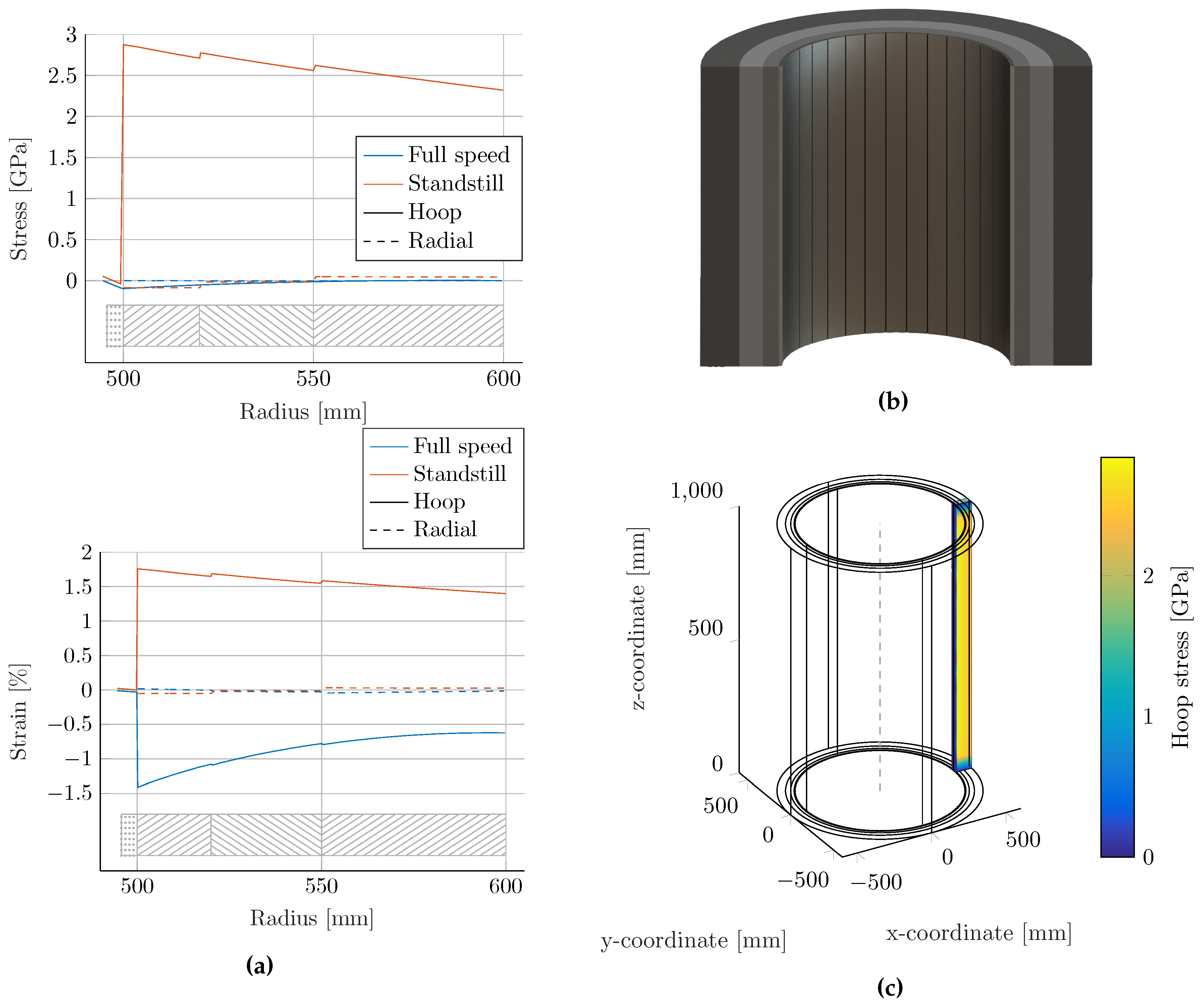
A hollow cylinder flywheel rotor design was found by iteratively solving the equations presented above for a multi-shell system. The final solution was then verified within the FEA software Solidworks, and the corresponding stresses and strains can be seen in
Figure 1a. For the analytical equations, the steel was simulated as segmented by assuming a low
(similar in approach to [
31]), and in FEA, it was done by simulating a 5
segment, as seen in
Figure 1c. The rotor is composed of four shells. The innermost shell was constructed of laminated spring steel sheet metal with a stack thickness of 5.5
, and the three outer shells are Toray T1000G (Toray CFA, Flower Mound, TX, USA)/epoxy composite material, with a total thickness of 10
. The ultimate specific energy for this design is 181
, at a rim speed of 1260
, with the composite pushed close to its theoretical limits [
32]. This value can be compared to 195
, the highest ultimate specific energy flywheel rotor known to date [
28], although that rotor had no electric machine (in contrast to this one). The hoop stress in the composite is increased due to the weight of the slit steel, which provides no hoop strength on its own. This sets an upper limit for steel thickness if optimizing for specific energy in a hollow rotor. On the other hand, the centrifugal forces within the composite rims increase with radius, causing tensile stress to build up, which can lead to delamination. Since the radial strength is much lower than the hoop strength for unidirectionally-wound composites, having steel on the inside can help keep the radial stress compressive (similar to [
31]). The composite shells were press fitted. Friction forces between consecutive shells were assumed to be zero. It is thus seen that high specific energy can be attained in hollow steel/carbon composite rotors, but that steel thickness is an important parameter.
Note that carbon composites can expand well in excess of 1.0%, far surpassing the strain limit of magnetic materials, as listed in
Table 1. Most materials cannot even sustain the fatigue limit of the unidirectional composite material, which for epoxy matrices is 0.6% [
33]. Any material mounted on the inside of a hollow cylinder will be pressed by centrifugal forces against an expanding composite shell.
This problem can be alleviated by placing the materials on low-friction sleds [
31]. Furthermore, a low-modulus plastic matrix can be put between sensitive materials to keep the effects from centrifugal forces compressive. The cycling fatigue behavior is not investigated, but could pose a problem. Another alternative is to infuse epoxy with magnetic materials, in exchange for a decrease of material functionality (a relative permeability
) [
1]. Further, there has been some attempts at making flexible magnets [
27,
35]. In this paper, a reluctance machine solution is proposed, since these can be made from strong steel, which is tolerant to straining and bending.
3. Switched Reluctance Machine
The SRM is considered a mechanically robust and relatively efficient topology, and its market penetration is increasing [
36]. The SRM has been considered for flywheel energy storage, for example in grid stabilization [
37,
38], in islanding operation [
39] and power smoothing [
40]. An SRM can be built with only
μ-metals, and the lack of exotic permanent magnet material makes them robust, fault tolerant and capable of high temperature operation while still achieving high torque [
41].
Many different topologies with different characteristics are found in the literature. Especially relevant for the hollow cylinders presented above are the external rotor variants [
42]. C-core stators have been proposed to simplify the winding process, allowing for simpler manufacturing processes [
43]. Although reduced torque ripple is not important for the flywheel rotor itself (since these generally have a high moment of inertia), secondary benefits include decreased losses, decreased vibration and more constant charging and discharging rates. The characteristic ripple torque of axial flux SRMs has been a subject under study [
44,
45,
46].
Based on the results in the literature, we propose an axial flux outer rotor machine for the hollow cylinder flywheel application, in an effort to avoid salient features and a long flux path in the back yoke. This is since the thickness of the steel layer on the inside of the flywheel was seen to be a major limiting factor above. The electric machine has c-core stators and two axial air gaps, similar to [
47], but with an inner stator and fewer rotor poles.
3.1. Machine Topology
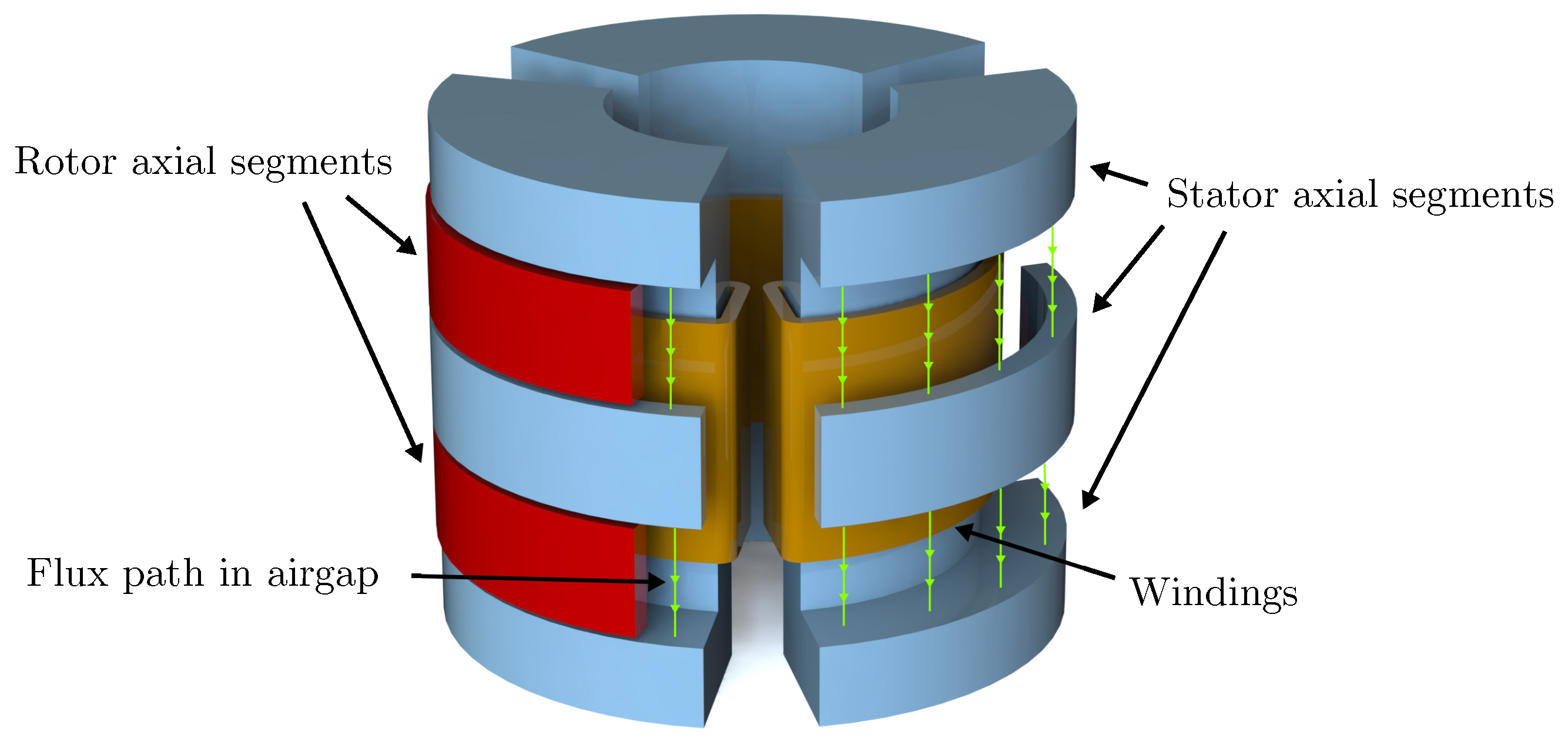
A 3D schematic view of the proposed axial flux switched reluctance machine is shown in
Figure 2. The orange windings (seen in the figure) can be magnetized, driving an axial magnetic field in the stator, drawn in blue. At the top and bottom of the stator, the field flows radially, and then axially, into the air gap. The rotor (drawn in red) flux is axial. Note that the machine laminations are not stacked in the same plane, although all electrical steel can be magnetized in a unipolar fashion. The rotor presented in the schematic drawing consists of one pole of laminated (in the
-plane) steel spanning 180
and a counterweight made of non-ferromagnetic stainless steel placed on the opposite side (not drawn). Note that more poles can be added in the circumferential direction, to change the torque/electrical frequency ratio. The stator is laminated in the
-plane and divided into three phases spaced 120
apart, allowing for more constant torque. The rotor can also be separated axially to increase torque (while also increasing reluctance due to a larger effective air gap). The schematic drawing above contains two axial poles and, thus, four axial air gaps. A 3-1-2 (# of poles for the stator, circumferential rotors and axial rotors, respectively) topology as seen in
Figure 2 has the minimum amount of circumferential poles.
There are a number of qualitative properties of this topology of interest: Since the air gap is axial, radial expansion during full speed will not affect the magnetic field path. The radial forces in a radial flux machine can be considerable and can affect the rotor fatigue characteristics with respect to cyclic loading. The proposed design has a weak stabilizing force in the radial direction. However, the rotor experiences axial negative stiffness around the air gap. This electric machine topology is intended to be mounted on a hollow flywheel with a set of separate magnetic bearings (which are needed to handle the high relative velocities on the inside of the rim). The axial negative stiffness from the electric machine must then be negated by axial magnetic bearings.
Losses
The high speeds of flywheel rotors require operation in a vacuum to reduce the effects of turbulent drag losses [
48]. With no convection or conductive heat transfer, it is hard to transport excess heat away. Black-body radiation is then one of the few mechanisms removing excess heat.
With higher rotational speeds, the frequency dependent losses become increasingly important. Both the rotor and stator can be operated with unipolar magnetization, decreasing the HB-curve area and, in turn, reducing losses. The unipolar control strategy has been previously shown to decrease losses for switched reluctance machines [
49].
Since the electric machine can be completely demagnetized, the standby losses can be kept low, decreasing the flywheel spin down rate.
The proposed geometry inherently has plateaus where
during a revolution and in turn, no back-emf, which decreases reactive power requirements on the power electronics [
50].
3.2. Prototype Construction
A proof of concept prototype (from hereon referred to as the prototype, in contrast to the full-scale machine analyzed in
Section 2) of the electric machine has been designed and built. The prototype has a single circumferential and axial pole in the rotor and three stator poles. One important objective of the prototype is to validate its basic electromagnetic functionality and also gather experiences from the mechanical assembly of this complex geometry, as presented in this paper. Regular bearings were used instead of magnetic bearings, and a composite shell was not fitted onto the rotor.
3.2.1. Rotor
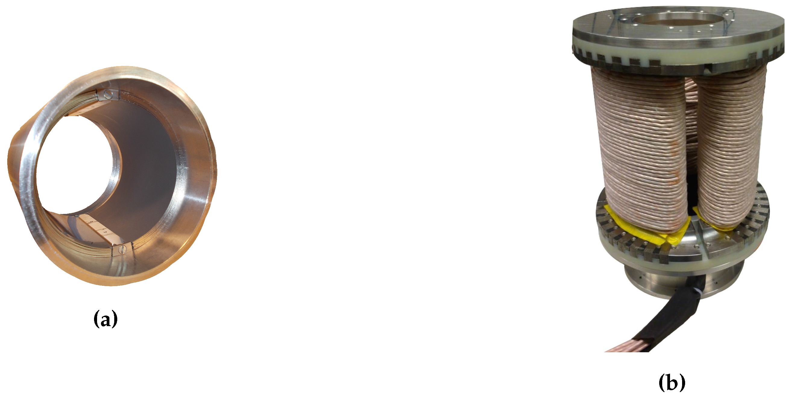
The prototype rotor mainly consists of an outer aluminum (7075-T6) cylinder with electrical- and stainless-steel laminations, each 0.5
thick, covering the inside of the cylinder, seen in
Figure 3a. Approximately half of the cylinders’ inner circumference is covered with electric-steel (M350-50A) [
51] and the other half with stainless-steel (X5CrNi18-10) [
52] (non-magnetic, acting as a counterweight). The steel densities differed slightly, so the amount of counterweight steel needed was determined by weighing during assembly. Not shown in
Figure 3a is the central steel shaft, connected to the rotor through an aluminum disk. The disk has a large external thread with a matching thread found on the inside of the rotor cylinder. The central shaft itself is press-fitted into a hole in the middle of the aluminum disk.
In order to keep the steel laminations in place, two wedges were placed in between the two lamination stacks. These wedges are fastened in the main aluminum cylinder by two screws, creating a stress concentration in the aluminum rotor (which can be three-times larger than the average stress of adjacent materials [
53]).
3.2.2. Stator
The stator is placed on a base centering it axially and radially inside the rotor, with the pedestal resting on the support structure. In order to make the stator structure rigid, it has a central cylinder with three rectangular holes cut out 120° apart, making room for the copper windings to wrap around. On the top, there is an aluminum lid and an isolating plastic plate both connected to the central cylinder; an identical plastic isolation plate can also be found on the bottom of the stator connected to the pedestal. Since the stator laminations are stacked in the
rz-plane, the density of iron will decrease with radius. To alleviate this, the lamination stacks are separated with small ferromagnetic wedges. These wedges help to keep the lamination stacks in place, but come with the drawback of increased eddy-current losses, as they are not laminated. Two larger ferromagnetic wedges are placed to decrease the dead-angle in between each phase, allowing the machine to produce a more constant torque while providing space for the copper windings to wrap around. Both of these wedges can be seen in
Figure 3b alongside the outer radius where the base meets the stator. Also seen in
Figure 3b are the three stator windings along the length of the stator, one around each stator segment. The main dimensions are presented in
Table 2.
3.2.3. Support Structure
The support structure keeps the rotor and stator in place while allowing for easy access to the interior of the machine. The structure consists of six steel square pipes linking two large aluminum plates together. In the center of each plate is a central hole where the bearing housings reside. The bearings used here are SKF self-aligning ball bearings (SKF, Göteborg, Sweden) that allow for a slight misalignment of the central axis without affecting the performance of the bearings, reducing the tolerances needed, reducing manufacturing costs and simplifying assembly.
3.3. Machine Parameters
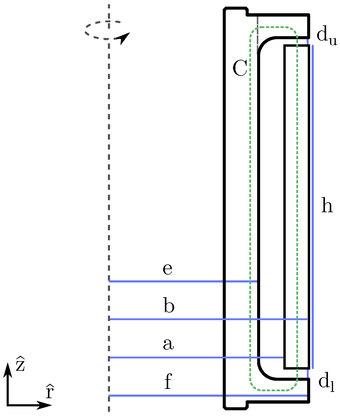
3.3.1. Analytical Model
Here, we present a simple analytical model for the prototype, to provide some insight on its operation. The relevant variables are presented in
Figure 4. A cylindrical coordinate system is used. Let
d and
q represent solutions when the rotor is aligned and unaligned, respectively, and let indexes
u and
l denote upper and lower.
Begin by considering Ampere’s law around curve
C, as drawn in
Figure 4. Assume the magnetic field is constant along the path of integration and that the steel is linear, isotropic, homogeneous and of high relative permeability. Then:
where
B is the magnetic flux density,
N is the number of winding-turns and
I is the winding current.
The system energy is thus (assume that the
q-axis field spreads out uniformly between the protruding stator ends):
where
and
is the volume occupied by a magnetic field in the air gap. The last two factors account for radial and angular displacement,
where
and
. The gradient of the degrees of freedom (
r and
θ) yields the force and torque on the rotor:
The axial force cannot be derived under the assumption of straight field lines. However, there will be negative stiffness around the point when . That point is an unstable equilibrium. To properly balance this force, we suggest magnetic bearings. The force equations also suggest that the radial position is in a stable equilibrium with positive stiffness around perfect radial alignment (the argument for radial stiffness is overly simplified, but there will be a radially stabilizing force regardless).
The inductance (when radially and axially aligned) can be computed as (where
A is area and Φ magnetic flux):
which:
3.3.2. Finite Element Analysis
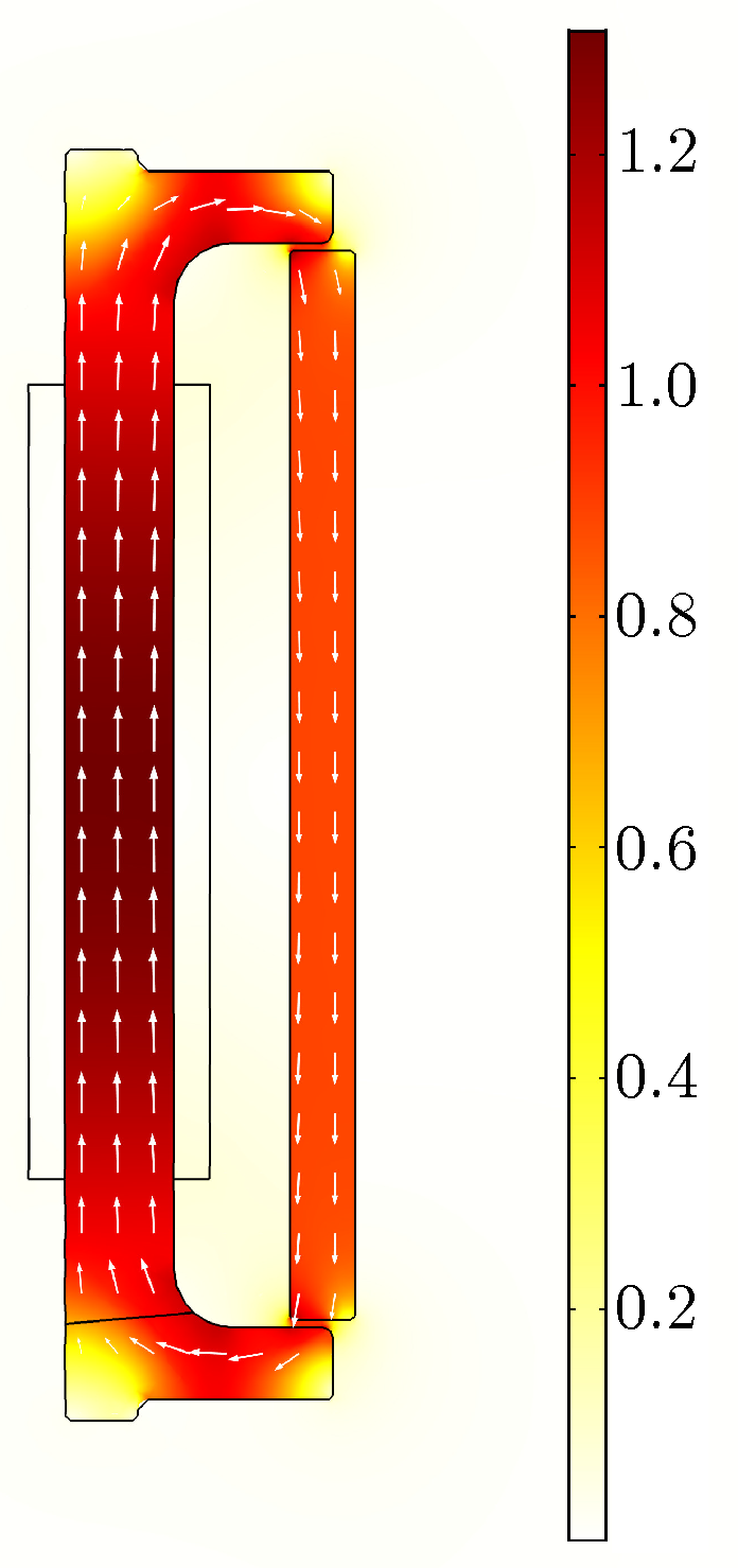
The prototype electric machine has been simulated in the commercial FEM package COMSOL Multiphysics (COMSOL, Burlington, MA, USA). A 3D geometry has been simulated with nonlinear steel.
Figure 5 shows the magnetic flux distribution through a cut section of the prototype.
Prototype inductance was computed via the magnetic energy. However, the magnetic energy for steel with BH-curves is not readily available from an FEM field solution. Therefore, the energy was numerically integrated with the definition [
54],
Simulations were performed with the magnetizing current I stepped from 0 o 20 in steps of 1 , and the solutions for the and -fields, as well as the volume elements for each mesh point were extracted. These were numerically integrated to attain the inductance of the motor from a simulation with nonlinear steel. The inductance for nonlinear steel was computed at 5 .
3.3.3. Experimental Inductance Measurement
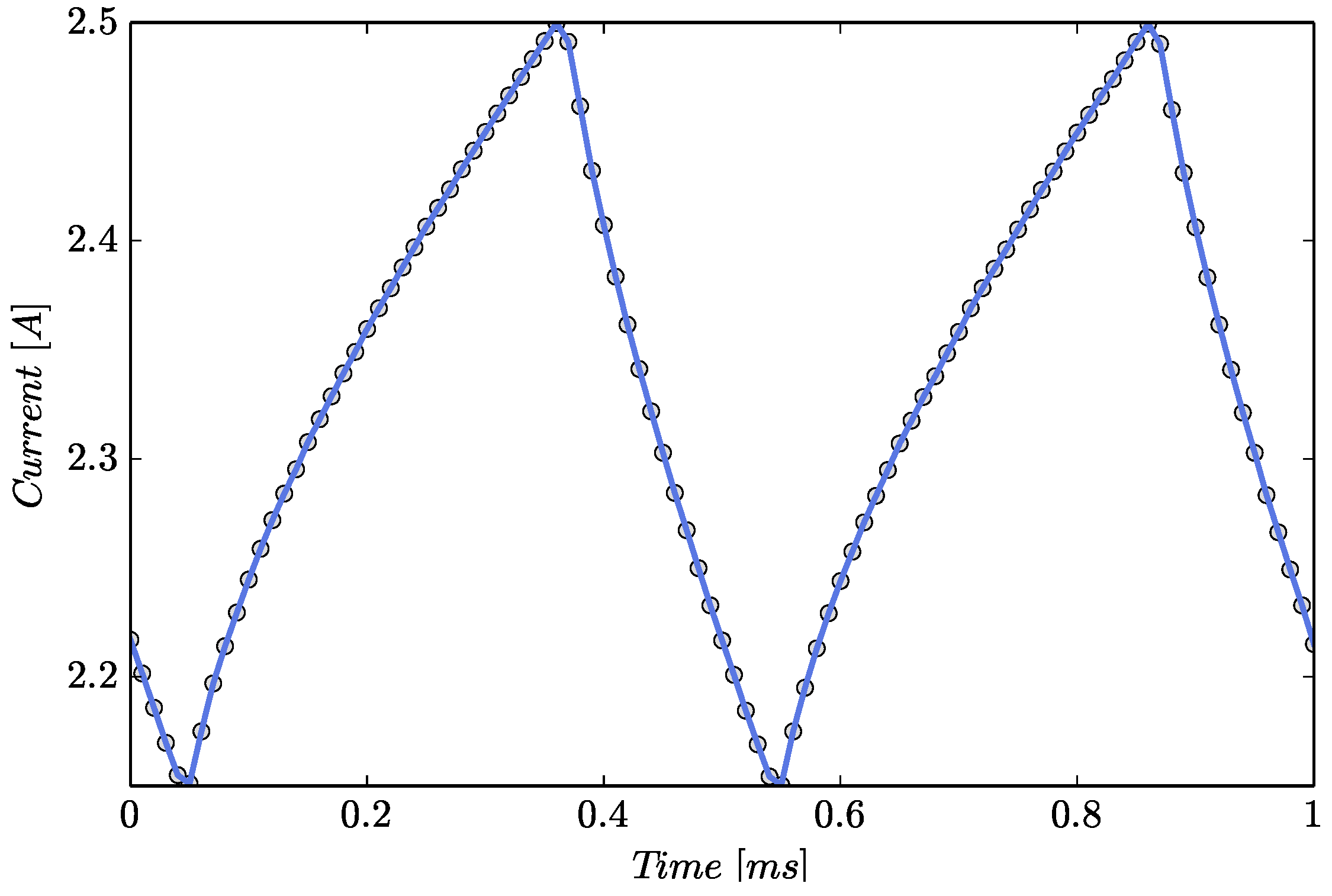
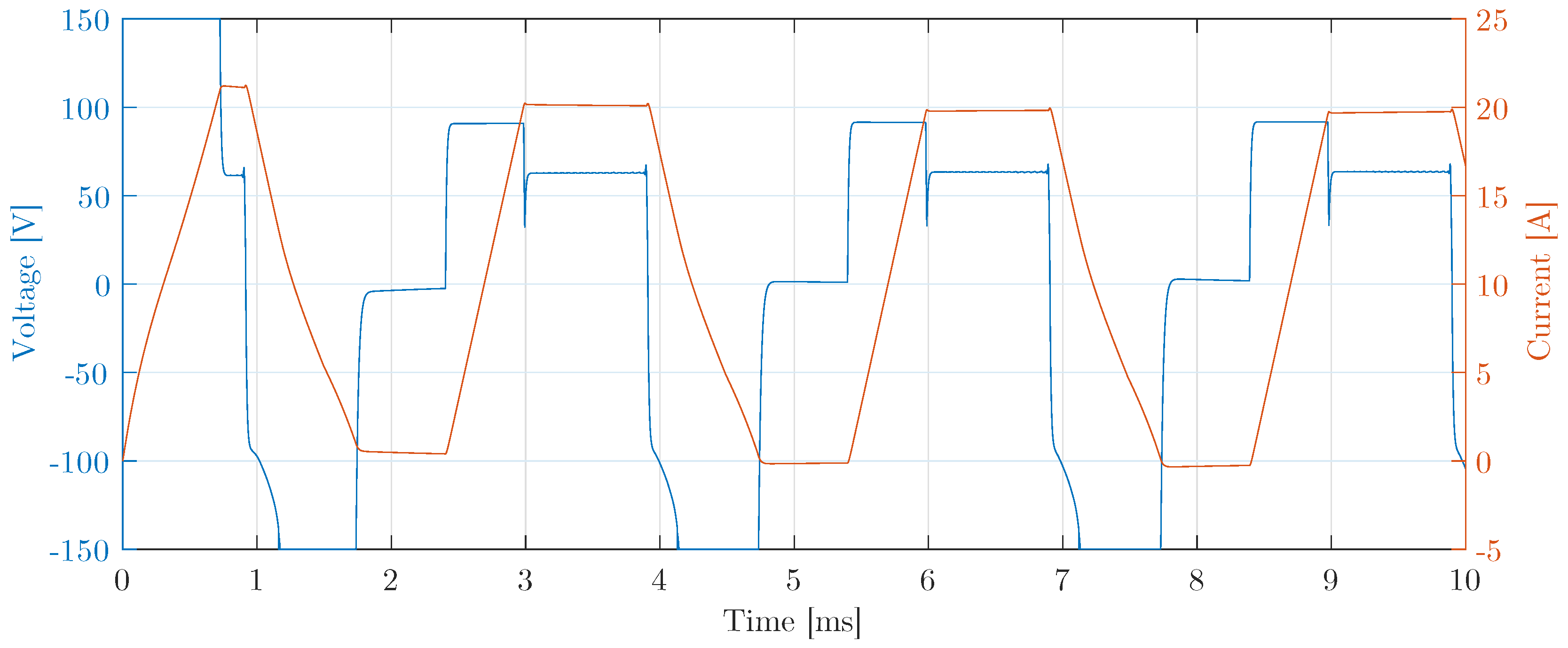
The inductance of the prototype was measured at low voltage/currents with an Agilent U1732A (Agilent Technologies, Santa Clara, CA, USA), at aligned and unaligned rotor position. The behavior at higher currents and steel saturation was obtained with system identification methods. By analysis of voltage and current measurements, as seen in
Figure 6, an
map could be produced.
Data Analysis
The measured data were analyzed by a system identification method derived in this section. The following definition was used for inductance
L (to account for nonlinearity):
where Φ is magnetic flux.
The prototype rotor was held fixed for each angle that was measured.
L was assumed constant during measurement, partly due to the fact that the rotor was fixed, but also because the current ripple was assumed small enough that a linear relation between flux and current exists in that region. The magnetically-induced potential difference is thus:
The circuit equation for one phase is then:
The current ripple amplitude
for each period was extracted from the measurement data, as well as the switching period
. These were used to approximate the current derivative:
Equation (
20) can be applied to every pair of points in a large dataset of measurements, and the inductance at each point is then computed with a least squares method.
When , eddy currents are induced that affect the measurements, which is a source of error with this technique.
Measurement Equipment
Current was measured with a Hall effect sensor (LEM LA 55-P, LEM, Zürich, Switzerland) with a bandwidth of 200
[
55]. Voltage was also measured via the Hall effect (LEM LV 25-P), with a 90% step response time of 40
[
56].
The measurement signal was converted to a noise-resistant current signal and fed from the transducers to a 10-bit ADC-unit. Each ADC-conversion took 4
, with a 120
accuracy at a bandwidth of 370
[
57]. The analog input aliasing filter was bypassed due to a low noise level during testing, as seen in
Figure 6.
The switching frequency of the current controller was lowered to 2
(from 20
) for the measurements to increase signal amplitude and increase data point density on the rising and decreasing slopes, as seen in
Figure 6. The sample rate was 100
. The current and voltage waveform measured in the winding was fed asynchronously through a high-speed first-in-first-out (FIFO) buffer from the measurement FPGA to a measurement data server for analysis.
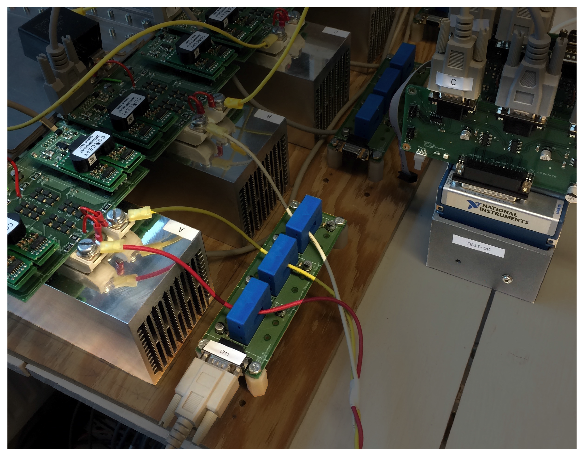
A separate H-bridge was used to control the current, as seen in
Figure 7. The current controller and sampling were done by a CompactRIO programmable automation controller (National Instruments, Austin, TX, USA). The custom circuit boards mounted on the CompactRIO were used to convert current signals into voltage signals.
Results
For each point in
Figure 8b, 2000 switching periods were recorded per angle and current. The prototype rotor was held fixed at 12 different angles, and the current was measured in steps of 1
from 0
20
. The result of different inductance estimations can be seen in
Figure 8a.
5. Discussion
The mechanical analysis was performed as a two-step process. Firstly a feasible solution in terms of stress was found with the help of the analytical equations, and secondly, this solution was verified in FEA. The full-scale machine was simulated with a 5 segmentation. For ease of construction, the prototype was constructed with 180 segments. Ideally, the rotor flux segments would be in the form of stacked wires, shaped for the optimal fill factor. These would then be stacked parallel to the axial flux path. The electric machine behavior would then be altered, due to flux tending to move less tangentially in the rotor.
The 3D flux path in the proposed topology implies 3D FEM solutions, which demand much in terms of computing power due to the large meshes required. Saturation behavior is also very important in SR machines, implying that a nonlinear material solver is needed, as well. In order to optimize the electrical properties of the machine, a faster approximation would need to be developed and verified.
The analytic solution presented did provide acceptable results for the geometry chosen, although underestimating leakage flux (manifested via a low ). It is likely that for an optimized design, in which for example, axial rotor segments are used, or a substantially shorter axial flux path in general, the analytical solutions will deviate more due to unmodeled leakage fluxes.
The practical construction of the prototype machine revealed a few important details. It was found to be hard to have laminated steel through all of the flux path, especially on the stator side of the air gap. A better solution than to use solid steel wedges could be to mount rings on the stator stacked in the
-plane; especially since some of the flux must move tangentially there. The winding process was found to simple and straightforward. Fixing the rotor laminations in place with wedges (as seen in
Figure 3a) required special manufacturing, which should be optimized. If using axially-oriented wires as suggested above, an epoxy matrix or similar would probably be beneficial.
The measurements in
Figure 8b seem to contain high saturation regions of decreasing inductance around
, which would imply negative torque. However, the actual torque is not negative, so the valley-shape is attributed to some physical loss-related effect and/or errors in the estimation assumptions, whose analysis is outside the scope of this paper. Most probably though, the effect is due to some of the smaller components in the stator not being laminated, in which eddy-currents are being induced. The effect can be seen in
Figure 6, where the current seems to rise faster just after a switch.
The dynamical simulation showed that the machine does have inductance plateaus, in which there is no back-emf. These plateaus can decrease the reactive power requirements of the power electronics, by allowing for the current to settle. The saturation behavior was included in the model, but no torque ripple or harmonic distortion was modeled. Although the system identification was evaluated at 240 different operating points, the angular resolution was deemed too low to model these properties satisfactorily.
A high peripheral velocity is not commonly optimized in electric machines. However, for an electric machine mounted close to the periphery of a flywheel energy storage, maximal peripheral velocity is directly related to the specific energy of the machine. The full-scale machine is seen to exhibit a large radius and high peripheral velocity when evaluated close to UTS.
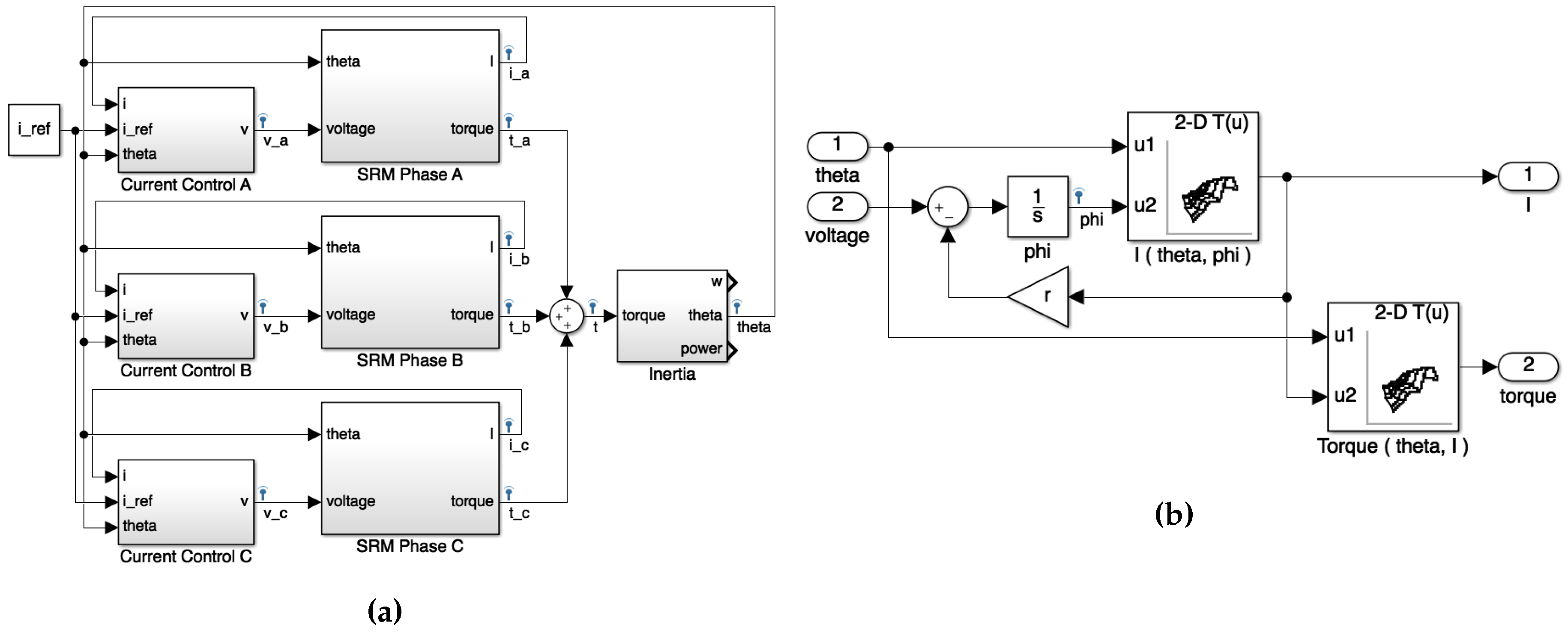
The inductance map can be used to compute mean mechanical power
P given speed
ω using the following relations:
where
is the mean torque developed when the rotor is passing from the
d to the
q position. The instantaneous torque can be found by differentiating the co-energy
[
50]:
The flux is substituted by integration of Equation (
17), which yields:
For the full-scale machine, a larger radius allows for larger winding area. A basic estimate of the full-scale machine rating can be extrapolated assuming all factors scale linearly. For example, assume the stator and rotor poles were tripled, as well as the winding area (assuming volume and sufficient cooling was available) and that the axial length of the rotor was increased and split into ten axial segments, with a ten-fold increase of parallelly-wound windings. Under the assumptions above, the power level of the full-scale topology would reach 50 . Within the scope of this work, some important aspects have been excluded, such as iron, eddy-current and copper losses, as well as heat transport. The power was also computed close to the UTS, which in a practical implementation is not feasible due to impurities in the composite fibers, as well as containment vessel restrictions (application-dependent).
Future work should include high-speed testing of this topology, in a full-scale flywheel energy storage machine, including magnetic bearings, a vacuum containment system and a carbon composite shell. Before that, the design should be optimized for an axial segmentation, and torque ripple should be investigated and consequently minimized. The flux path should be improved so that no unlaminated steel is magnetized.
6. Conclusions
A hollow cylinder flywheel energy storage rotor design was presented, with an ultimate rotor specific energy of 181
(evaluated close to UTS). This rotor includes electromagnetically-active material in the form of steel, unlike the 195
record rotor [
28], which was accelerated with an air turbine. This value compares favorably to other high-end flywheels, such as the Flybrid Systems Formula 1 flywheel rotor, which had a specific energy of 22.2 Wh/kg (although not ultimate specific energy). The mechanical analysis of the flywheel was performed with an analytical formulation assuming planar stress in concentric shells of orthotropic (unidirectionally tangentially wound) carbon composites, which was then verified by 3D FEM simulations.
A novel thin outer-rotor switched reluctance machine was proposed and presented, intended to be mounted on the inside of a hollow cylinder flywheel. Numerical analysis evaluated close to UTS found that the electric machine could theoretically reach rim speeds of 1050 m/s for the electromagnetically-active material (the rim speed of the outermost composite shell was higher). High rim speed is especially relevant for flywheel energy storage with shaft-less rotors, when the focus is high specific energy. The motor topology is thus an enabling factor for hollow flywheel designs, which does not require shaft-rim connections and which may have lower cost than other designs.
A small-scale prototype was constructed, and the electrical properties were measured experimentally and verified against an analytical model and an FEM simulation. The measurements for this machine can be used as a means of verification for further studies and models of this machine concept, for example when increasing poles (axially and circumferentially). The prototype rotor consisted of one laminated pole covering 180, leading flux in the axial direction, through axial air gaps into c-shaped stator cores, wound into three different phases. The axial air gaps lead to smaller radial forces (compared to a radial flux machine), and axial forces are zero when the rotor is centered perfectly in the axial direction.


