Article

An Improved LCL Filter Design in Order to Ensure Stability without Damping and Despite Large Grid Impedance Variations

by
Marwa Ben Said-Romdhane
1,*,
Mohamed Wissem Naouar
1,
Ilhem Slama Belkhodja
1 and
Eric Monmasson
2
1
Université de Tunis El Manar, Ecole Nationale d’Ingénieurs de Tunis, LR 11 ES 15, Laboratoire des Systèmes Electriques, BP 37-1002 Tunis le Belvédère, Tunisie
2
Laboratoire des Systèmes et Applications des Technologies de l’Information et de l’Energie, University of Cergy-Pontoise, 33 bd du Port, 95000 Cergy-Pontoise, France
*
Author to whom correspondence should be addressed.
Energies 2017, 10(3), 336; https://doi.org/10.3390/en10030336
Submission received: 4 November 2016 / Accepted: 9 February 2017 / Published: 9 March 2017
(This article belongs to the Special Issue Control and Communication in Distributed Generation Systems)

Abstract

:
With the smart grid revolution, there is a growing interest in the use of power converters associated to LCL filters to interface between the main utility grid and loads or renewable energy sources. LCL filters are commonly used mainly due to their low cost and high filtering performances. To achieve these performances, it is necessary to meticulously pick out the LCL filter parameters, taking into account grid code requirements and grid configuration and/or conditions. Several methodologies for LCL filter design have been presented and discussed in the literature. The main goal of this paper is to propose a simple, robust and systematic design methodology for LCL filter parameter tuning. The considered design methodology is aimed to overcome the shortcomings of classical design methodologies, namely, stable operation under different grid configurations and conditions. Compared to previous works, the proposed design methodology allows the achievement of robust LCL filter design with regard to large grid impedance variations without the use of any damping method. Also, it takes into account accuracy of capacitor standard values and proposes a simple design method for the converter side inductor that avoids saturation problems. An example of LCL filter design is presented and discussed. The obtained filter parameters were firstly tested using a Matlab-Simulink software tool. After that, they were tested through the development of an experimental set-up. The obtained simulation and experimental results show the reliability and efficiency of the proposed design methodology.

1. Introduction

For several industrial applications, such as adjustable speed drives or renewable energy sources, a three-phase grid connected converter is required to control the power flow with the grid. For adjustable speed drives, the use of grid connected converters is an interesting solution to ensure bidirectional power flow since regenerative operation is frequently achieved. Moreover, this solution provides many features like low current harmonic distortion factor (THD) and the possibility to work with unity power factors. For renewable energy sources, like wind turbines and photovoltaic systems, the use of grid connected converters became a key solution for efficient control of active and reactive power injected to the grid [1,2].
With the smart grid revolution, modern systems based on grid connected converters must meet new grid code requirements [3,4]. For this purpose, companies that produce these systems tend to have appropriate solutions to comply with different related standards and their ongoing changes in the near future. Among considered solutions, LCL filters are used in association with grid connected power converters in order to limit the current harmonic injection due to semiconductor switching. This solution allows reductions in cost as well as size and encumbrance compared to conventional L filter-based solutions [5,6,7]. However, the use of LCL filters can lead to resonance and instability problems since their safe operation can be affected by the grid impedance value, which varies according to grid configuration and conditions (weak or stiff grid). Thus, the main challenge of LCL filter design for grid connected power converters is to ensure stable operation despite large grid impedance variations.
Several LCL filter design methodologies were presented and discussed in the literature [8,9,10]. All of them tried to perform efficient tuning of LCL filter parameters according to different constraints. Among these constraints, there are: the grid current THD value [11], the consumed reactive power [12], the resonance frequency [13], the maximum current ripple [14], the maximum filter volume and size [15,16]. However, up to now, only a few research works have tried to provide robust LCL filter designs available for different grid conditions (weak or stiff grid conditions) characterized by large grid impedance variations [17]. In fact, the grid impedance varies significantly according to the grid configuration (low, medium or high voltage lines, wires length…) [18] and conditions (weak or stiff grid) [19] as well as parallel converters connection [20]. In most cases, the stable operation of LCL filters is ensured through active damping control [21,22,23,24,25,26] or by adding passive damping resistors [27,28,29,30]. However, according to [31,32,33], for PI-based current control (with grid current feedback), it is possible to place the resonance frequency in a stable region where damping is not required. Hence, by placing the resonance frequency variation inside this stable region, the grid current feedback alone is found to be sufficient for stable operation.
The aim of this paper is to present a simple, robust and systematic LCL filter design methodology. The proposed design methodology is applied to low power converters and high power ones thanks to the use of parallel interleaved voltage source converters [34]. While mainly based on [9], it introduces additional features that allow stable operation without damping. In fact, very large grid impedance variations and accuracy of filter capacitor parameters are taken into account for the design process. Accordingly, the resonance problems are avoided and the system stability is ensured even for important grid impedance changes. This is achieved through an accurate choice of the filter parameters by placing the resonance frequency, which is a function of grid impedance and filter capacitor, in a stable region where no damping is required. Moreover, the considered design methodology avoids inductor saturation problems by accurately computing the current ripples so that the converter side current does not exceed the inductor saturation current. The proposed design methodology is available for grid connected power converters controlled through PI-based current controllers and when the grid current is the used feedback variable. In this work, the grid impedance is assumed to reach up to 13 mH and each step of the considered design methodology is detailed, justified and discussed. To summarize, compared to previous related works, the proposed design methodology considers the following constraints that may influence the system stability: (1) large grid inductance variations, overestimated to 13 mH; (2) accuracy of filter capacitor, overestimated to ±5%; (3) LCL filter inductor saturation problems; consequently, the filter parameters are designed so that, even under the abovementioned constraints, the two following points are ensured: (1) system stability without damping; (2) high filtering performances (low harmonic attenuation rate δ and grid current THD value less than 5%).
This paper is organized as follows: firstly, in Section 2, the mathematical model of an LCL filter is presented. Then, in Section 3, the step-by-step LCL filter design methodology aimed to achieve robust tuning of the LCL filter parameters is detailed and discussed. After that, Section 4 presents a case study for LCL filter design with simulation results achieved under Matlab-Simulink software tool. Finally, in Section 5, the considered design methodology was verified through experimental tests. The obtained experimental results are quite similar to those of simulation and prove effectiveness of the used design methodology.

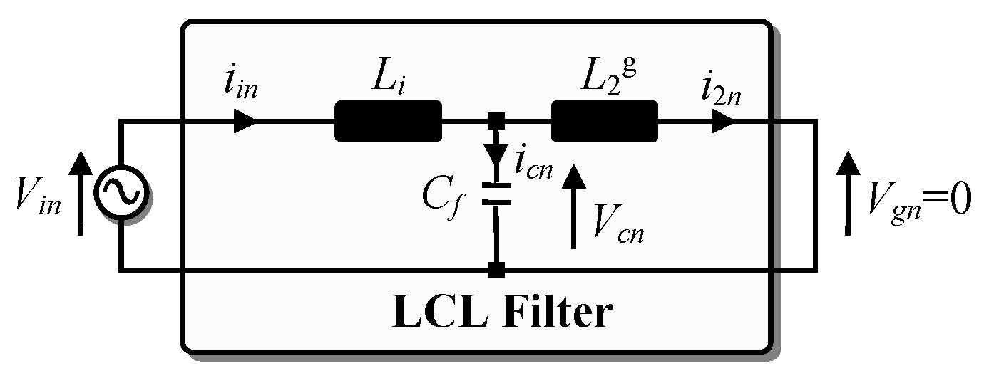
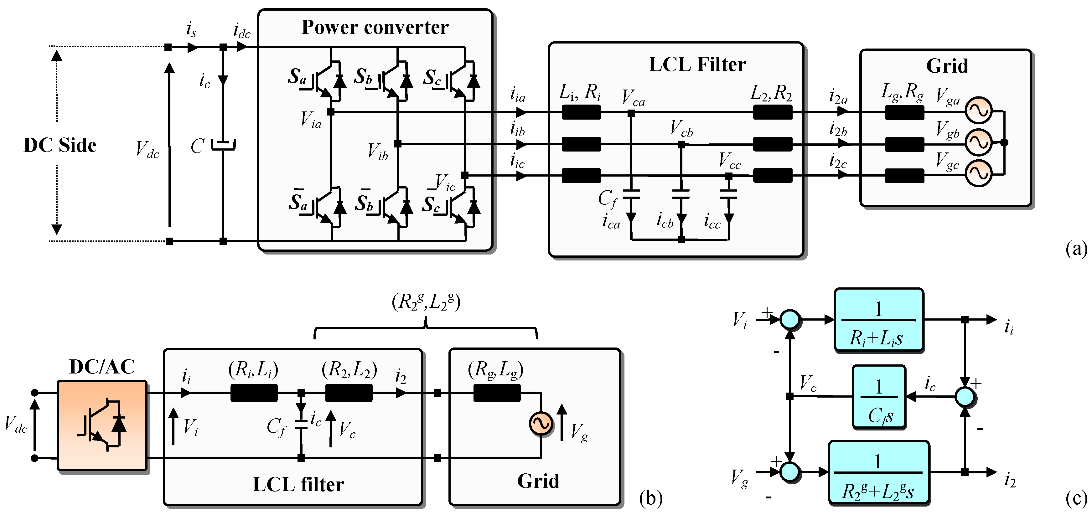
2. LCL Filter Mathematical Model

The power circuit of a three phase grid connected power converter is presented in Figure 1a. As depicted in this figure, the LCL filter is used to interface between the grid and the power converter. Vg(a,b,c) (respectively i2(a,b,c)) refer to the grid voltage vector components (respectively the grid current vector components) in the stationary reference frame, while Vi(a,b,c) (respectively ii(a,b,c)) refer to the components of the output power converter voltage vector (respectively the components of the output power converter current vector) in the stationary reference frame. Li (respectively L2) refer to the converter side inductor of the LCL filter (respectively the grid side inductor of the LCL filter), while Ri (respectively R2) refer to the internal resistance of the converter side inductor, (respectively the internal resistance of the grid side inductor). Cf refer to the LCL filter capacitor, while Vc(a,b,c) (respectively ic(a,b,c)) refer to the voltage across the filter capacitor vector components (respectively the capacitor current vector components) in the stationary reference frame. Lg (respectively Rg) refer to the inductive part of the grid impedance (respectively the resistive part of the grid impedance), while L 2 g (respectively R 2 g ) refer to the filter grid side inductor in series with the grid inductor (respectively the internal resistance of the filter grid side inductor in series with the internal resistance of the grid inductor).
Figure 1b presents the equivalent single phase representation of the power circuit with LCL filter. According to this figure, the LCL filter equations are as follows:
i i = V i V c s L i + R i
i 2 = V c V g s L 2 g + R 2 g
V c = i c s C f
Based on Equations (1a)–(1c), the block diagram of the LCL filter is given by Figure 1c. As shown in this figure, the transfer function of the LCL filter is the ratio between the output current i2 and the input voltages Vi and Vg. It is computed based on the superposition principle. The first transfer function is obtained by setting the Vg input equal to zero. According to Equations (1a)–(1c), it is given by (2a). While the second transfer function is obtained by setting the Vi input equal to zero and is given by Equation (2b):
F 1 = i 2 V i | V g = 0 = 1 C f L 2 g L i s 3 + s 2 C f ( L 2 g R i + L i R 2 g ) + s ( C f R 2 g R i + L i + L 2 g ) + R 2 g + R i
F 2 = i 2 V g | V i = 0 = ( 1 + s 2 C f L i + s C f R i ) C f L 2 g L i s 3 + s 2 C f ( L 2 g R i + L i R 2 g ) + s ( C f R 2 g R i + L i + L 2 g ) + R 2 g + R i
The whole transfer function of the LCL filter is obtained through superposition of F1 and F2 and is given by the following equation:
i 2 = V i + V g ( 1 + s 2 C f L i + s C f R i ) C f L 2 g L i s 3 + s 2 C f ( L 2 g R i + L i R 2 g ) + s ( C f R 2 g R i + L i + L 2 g ) + R 2 g + R i
The main objective of the LCL filter is to reduce the high-order current harmonics at the used switching frequency. Figure 2 shows the equivalent single phase representation of the LCL filter power circuit for the n-harmonic neglecting the resistors effect and considering that the grid voltage is an ideal sine wave voltage source. Vn and in are respectively the voltage and current n-harmonic components.
For the n-harmonic (Figure 2) and based on Equation (3), neglecting the resistors effect, the transfer function between the grid current i2n and the converter voltage Vin is expressed by Equation (4a). According to this equation, the LCL filter resonance frequency (that corresponds to zero impedance) is given by Equation (4b):
H = i 2 n V i n = 1 C f L 2 g L i s 3 + s ( L i + L 2 g )
ω r e s 2 = ( 2 π f r e s ) 2 = L 2 g + L i L 2 g L i C f
Since the LCL filter resonance frequency is much lower than the switching frequency, it is common to consider the capacitor impedance negligible for switching frequency. In this case, the converter will only see the impedance of the converter side inductor [35]. Based on this approximation and Figure 2, the transfer function between the converter current iin and the converter voltage Vin can be approximated as in (5a) [35]. According to Equations (4a) and (5a), the transfer function between the grid current i2n and the converter current iin for high frequencies, is given by Equation (5b). At the switching frequency, the previous equation becomes equal to (5c):
i i n V i n = 1 s L i
i 2 n i i n = i 2 n V i n V i n i i n = L i C f L 2 g L i s 2 + ( L i + L 2 g )
| i 2 s ω i i s ω | = Z L C 2 | ω r e s 2 ω s ω 2 |
Z L C 2 = 1 L 2 g C f
ω s ω 2 = ( 2 π f s ω ) 2

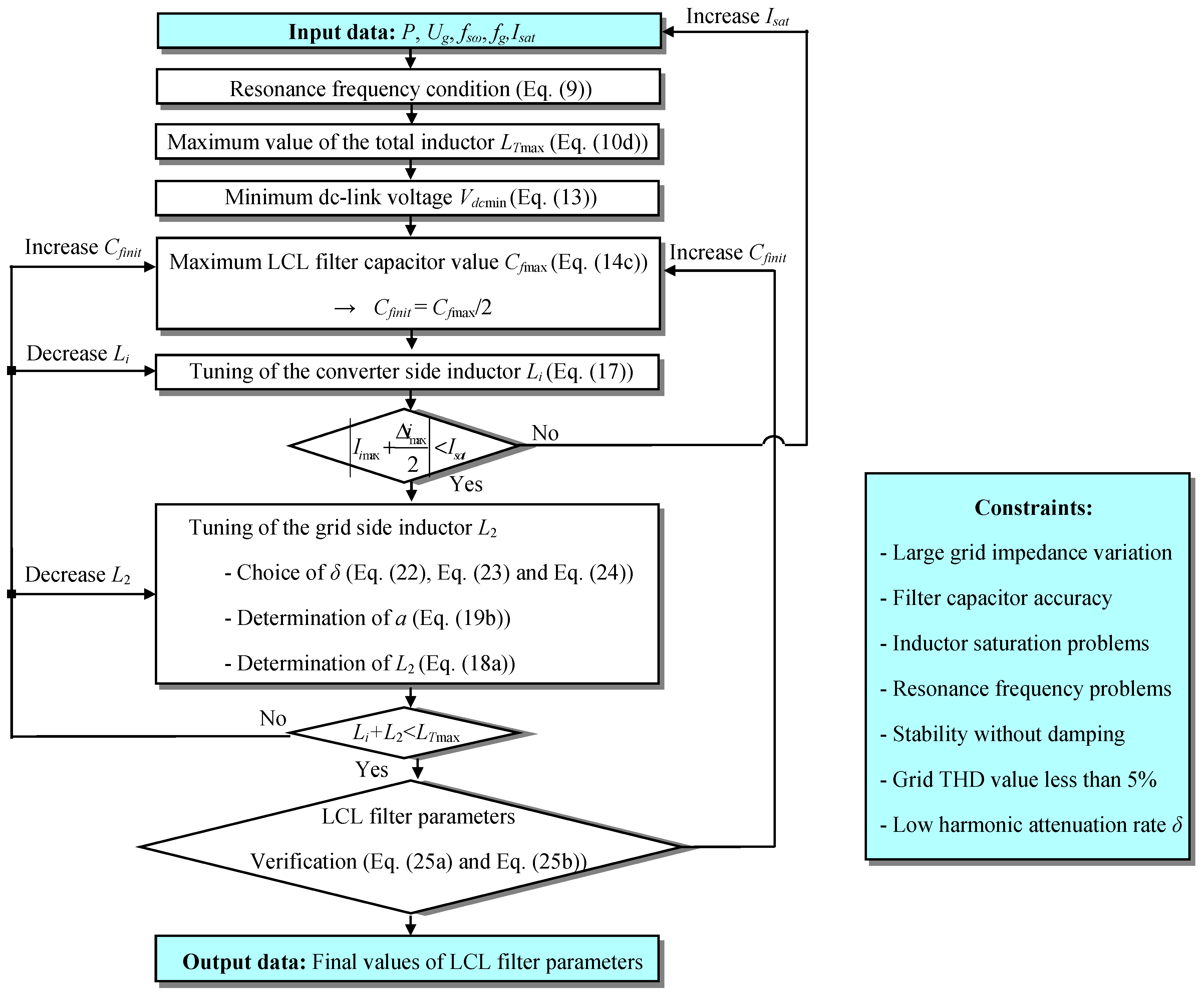
3. LCL Filter Design Methodology

The LCL filter design methodology is aimed to meet grid code requirements through efficient attenuation of high order current harmonic components on the grid side. It requires the following input data.
-
The line-to-line RMS grid voltage Ug;
-
The rated active power of the system P;
-
The rated frequency of grid voltage fg;
-
The switching frequency of the converter f;
-
The saturation current of the LCL filter inductors Isat.
Then, the LCL filter parameters are tuned according to the following steps.

3.1. Resonance Frequency Condition

According to Equation (4b), the resonance frequency fres depends on:
-
The filter inductors Li and L2;
-
The grid inductor Lg;
-
The filter capacitor Cf.
The filter inductors Li and L2 can be considered constant since their corresponding saturation current is not exceeded. However, the grid inductor Lg can have a large set of values. Based on [17,18,19,20], the ratio Rg/Xg varies according to the grid configuration (low, medium or high voltage lines, wires length…) and conditions (weak or stiff grid). It includes also the leakage inductance of the transformer. The capacitor value has a small error that depends on capacitor accuracy. Low cost capacitors have an accuracy that typically varies between ±5%. The range of resonance frequency variation is given by Equation (6) since the resonance frequency is a decreasing function for both Lg and Cf variables:
f r e s min = 1 2 π L 2 + L g max + L i ( L 2 + L g max ) L i C f max f r e s ( L g , C f ) f r e s max = 1 2 π L 2 + L g min + L i ( L 2 + L g min ) L i C f min
On the other hand, and in order to avoid resonance problems, the resonance frequency fres must be higher than 10 times the grid frequency fg and less than half of the switching frequency f [9]. So, in order to avoid resonance problems due to large grid impedance variations and capacitor values errors, Equation (7) must be verified:
10 f g f r e s min f r e s ( L g , C f ) f r e s max f s ω / 2
According to [31], when PI-based current control is used with grid current feedback, two critical frequencies fcmin and fcmax can be defined. The first one (fcmin) is equal to f/6, while the second one (fcmax) is equal to f/2. In [31], it is concluded that the PI-based current control can be achieved without active or passive damping if the resonance frequency fres is inside the interval [fcmin, fcmax] as shown in Equation (8):
f c min = f s ω 6 < f r e s ( L g , C f ) < f c max = f s ω 2
Consequently, for PI based grid side current control, the variation range of fres should be placed in a stable region as shown in Equation (9), which is deduced from (7) and (8):
10 f g f c min < f r e s min f r e s ( L g , C f ) f r e s max < f c max = f s ω 2

3.2. Maximum Value of the Total Inductor

The sum of the LCL filter inductor values should be as small as possible. This makes the losses and the voltages drops in the filter negligible. It improves also the speed and the dynamic of the system. To this purpose, the total inductor value should be lower than 0.1 pu as shown in Equation (10a), where LTBase is the base value of the total inductor value and ZBase is the base impedance [9]. Consequently, the maximum value of the total inductor is expressed by Equation (10d):
L T max = ( L i + L 2 ) max = 10 % L T B a s e
where   L T B a s e = Z B a s e 2 π f g
Z B a s e = U g 2 P
L T max = 10 % U g 2 2 π f g P

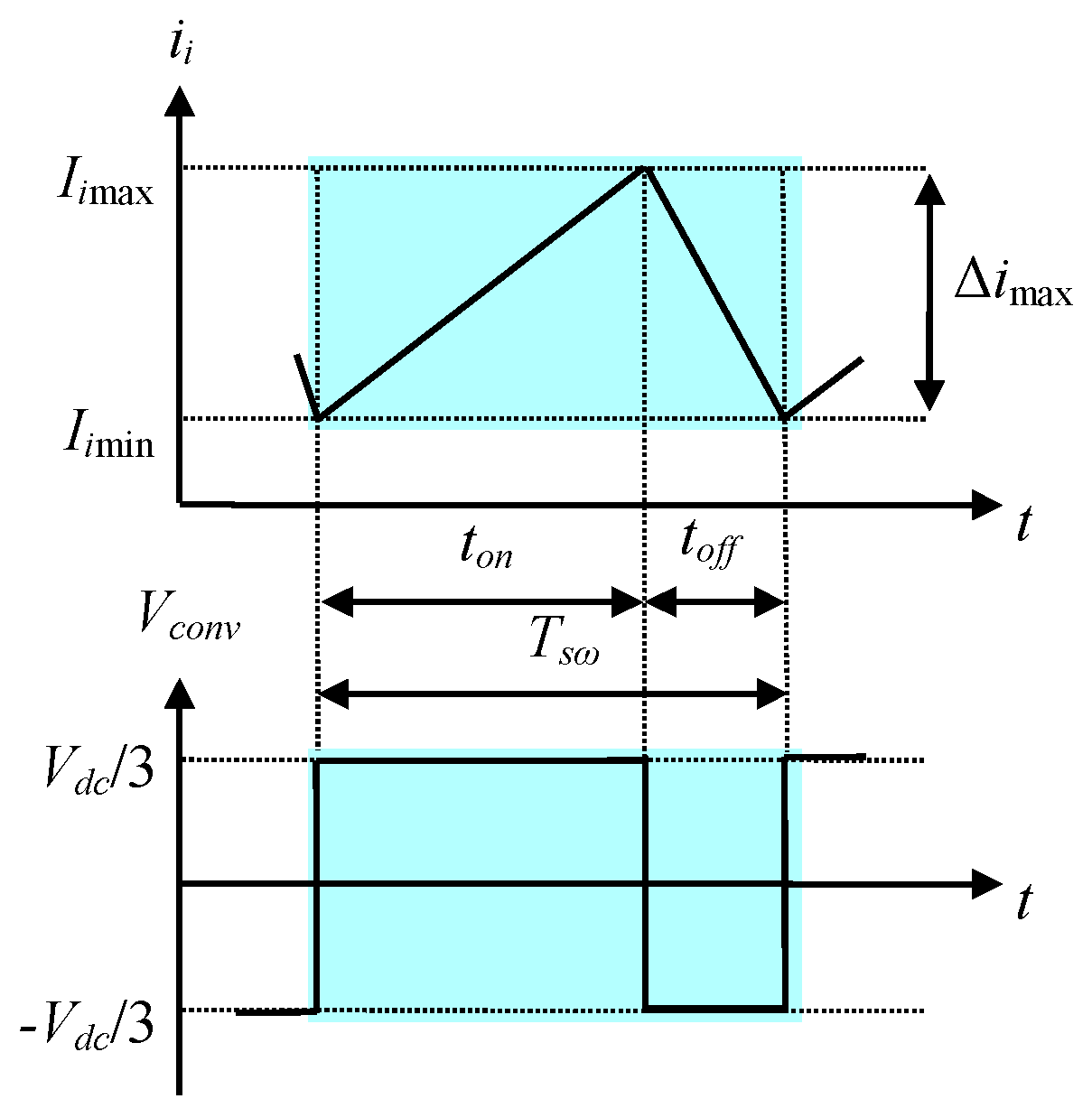
3.3. Minimum DC-Link Voltage

For fundamental signals, the LCL filter can be approximated to an inductor with a value LT equal to the sum of the two inductor values Li and L2. This is mainly due to the fact that the LCL filter is designed so that the capacitor has great impedance value for fundamental signals. Based on Figure 1b and neglecting the influence of different resistors, the relationship between the converter and grid voltages can be expressed in complex form as follows:
V i _ = V g _ + j L T ω g i 2 _
The previous equation allows addressing the Fresnel diagram depicted in Figure 3. From this diagram, the maximum magnitude of the voltage at the output of the converter Vimax is given by Equation (12):
V i max = V g max 2 + ( L T max ω g I 2 max ) 2 where   I 2 max = 2 3 P U g
For the case of Space Vector Modulation SVM process, the required minimum DC-link voltage Vdcmin is computed according to Equation (13):
V d c min = 3 V i max

3.4. Maximum LCL Filter Capacitor Value

The LCL filter capacitor is designed so that its consumption of reactive power is less than λ% of the rated power P as shown in Equation (14a) [36,37,38]. In this equation, Qc denotes the reactive power consumed by the filter capacitor and λ is a positive factor chosen generally equal to or lower than 5% [36,37,38]. According to Equations (14a) and (14b), the maximum value of the filter capacitor can be expressed as in Equation (14c):
| Q c | λ % | P |
Q c = U g 2 C f ω g
C f max = 5 % P 2 π f g U g 2
It should be noted that when the value of the capacitor is too low, the inductor values must be too high. For this reason, it is recommended to start with a capacitor value equal to one-half of the maximum value and then, if some of the constraints cannot be satisfied, increase it up to the maximum value.

3.5. Tuning of the Converter Side Inductor

The converter side inductor is specifically designed in order to reduce converter current ripple in the worst case. This current ripple is caused by the pulsed voltage generated by the converter. During the switching operation, the worst case which leads to a maximum converter current ripple is obtained when the applied converter voltage varies from −Vdc/3 to Vdc/3 [35]. Figure 4 shows a waveform example of the converter current ii with regard to the applied converter voltage Vi. In this figure, ton and toff refer to the time taken by the control signal at high and low logical level, respectively. T is the switching period.
According to Figure 4, the maximum converter current ripple and the converter side inductor value are given by Equations (15a) and (15b), respectively. The converter side current ii must verify Equation (16) in order to avoid inductor saturation problems. According to Equations (15b) and (16), the minimum converter side inductor value can be deduced based on Equation (17):
Δ i max = V d c 6 L i f s ω
L i min = V d c 6 f s ω Δ i max
| I i max + Δ i max 2 | < I s a t where   I i max = I 2 max   ( for   high   frequencies )
L i min > V d c 12 f s ω ( I s a t I i max )

3.6. Tuning of the Grid Side Inductor

The grid side inductor is designed in order to limit the grid current harmonics according to standards and grid code requirements. According to the IEEE 519-1992 standard, the grid current THD value must be under 5% [39]. The relation between the converter side and the grid side inductors is given by Equation (18a):
L 2 = a L i
where   0 a a max   and   a max = L T max L i 1
By substituting the grid side inductor L2 by its expression given by Equation (18a) and supposing the grid inductor Lg equal to zero, Equation (5c) becomes equal to Equation (19a), where δ is the harmonic attenuation rate. It represents the relation between the converter current and the grid current at the switching frequency. The positive solution of Equation (19a) is given by Equation (19b):
δ = | i 2 s ω i i s ω | = 1 | 1 + a ( 1 L i C f ω s ω 2 ) |
a = 1 + δ δ a 1
where a1 = LiCfω2 − 1. Based on (18a) and (19b), the grid side inductor can be expressed as follows:
L 2 = a L i = L i ( 1 + δ ) δ a 1
By substituting the grid side inductor L2 by its expression given by Equation (20), fresmin (expressed by Equation (6)) becomes equal to (21a). Also, fresmax (expressed by Equation (6)) becomes equal to (21b):
f r e s min = 1 2 π δ a 2 + L i δ a 3 + L i 2 C f max
f r e s max = 1 2 π δ b 2 + L i δ b 3 + L i 2 C f min
where a2 = Li + a1Lgmax + a1Li, a3 = (Li + a1Lgmax)LiCfmax, b2 = Li + a1Lgmin + a1Li, b3 = (Li + a1Lgmin)LiCfmin. According to Equations (9), (21a) and (21b), fresmin and fresmax must verify the conditions expressed by Equations (22) and (23), respectively. These equations provide a condition on the value of the harmonic attenuation rate δ which ensures a resonance frequency variation included in the stable region. On the other hand, the desired harmonic attenuation rate must be greater than a minimum harmonic attenuation rate δmin that corresponds to amax. This condition is given by Equation (24):
f c min 2 = f s ω 2 36 < f r e s min 2 = 1 4 π 2 δ a 2 + L i δ a 3 + L i 2 C f max   δ < 36 L i ( 2 π f s ω L i ) 2 C f max a 3 ( 2 π f s ω ) 2 36 a 2     1 st   δ   condition
f r e s max 2 = 1 4 π 2 δ b 2 + L i δ b 3 + L i 2 C f min < f c max 2 = f s ω 2 4   δ < 4 L i ( 2 π f s ω L i ) 2 C f min b 3 ( 2 π f s ω ) 2 4 b 2     2 nd   δ   condition
δ > δ min = 1 | 1 + a max a 1 |     3 rd   δ   condition
Moreover, it should be noted that the current harmonics are lower when δ is lower. Consequently, the grid current THD value is lower when the harmonic attenuation rate δ is lower. Based on what has been said and conditions given by Equations (22)–(24), a desired harmonic attenuation rate δ can be easily selected. After that, the value of a can be computed according to Equation (19b). Finally, the value of the grid side inductor L2 is deduced based Equation (18a).

3.7. LCL Filter Parameter Verification

The current at the input of the LCL filter contains the fundamental current and the high frequency harmonics. The objective of the LCL filter is to attenuate these harmonics and obtain only the fundamental current at the output of the filter. The high frequency harmonics should flow through the low impedance path composed by the filter capacitor rather than their injection into the grid. To this purpose, for the obtained LCL filter parameters, conditions given by Equations (25a) and (25b) must be fulfilled:
For   fundamental   signals :   Z C f > >   Z L 2     1 2 π f g C f > >   2 π f g L 2
For   high   frequencies :   Z C f < <   Z L 2     1 2 π f s ω C f < <   2 π f s ω L 2
where ZCf and ZL2 are the capacitor impedance and the filter grid side inductor impedance, respectively.

Algorithm of the LCL filter design methodology

Figure 5 shows the algorithm of LCL filter design methodology that allows tuning of LCL filter parameters according to the input data of the controlled system.

4. Case Study for LCL Filter Design

4.1. Application Design Methodology

The step-by-step LCL filter design methodology has been applied to a system with a line-to-line RMS grid voltage Ug equal to 400 V, a rated power P equal to 4 kW, a rated frequency of grid voltage fg equal to 50 Hz and a switching frequency f equal to 10 kHz. Based on the design methodology presented and detailed in Section 3, the LCL filter parameters are computed as follows:
-
Maximum value of the total inductor LTmax
According to Equation (10d), the maximum value of the total inductor LTmax is equal to 12.7 mH.
-
Minimum DC-link voltage Vdcmin
The maximum grid current I2max and voltage Vgmax are equal to 10 A and 325 V, respectively. According to Equation (12), the maximum converter voltage Vimax is equal to 328 V. Consequently, based on Equation (13), the required minimum DC-link voltage Vdcmin is equal to 567 V. We choose Vdc equal to 600 V.
-
Maximum LCL filter capacitor value Cfmax
According to Equation (14c), the maximum LCL filter capacitor value Cfmax is equal to 4 µF. A value of 2 µF is chosen for the LCL filter capacitor.
-
Tuning of the converter side inductor Li
The saturation current of the filter inductors Isat is equal to 12 A and the maximum converter current Iimax is equal to 10 A. So, according to Equation (15a), the maximum converter current ripple Δimax is equal to 4 A. Based on Equation (17), the minimum converter side inductor value is equal to 2.5 mH. A value of 5 mH is chosen for the converter side inductor which presents 40% of the total LCL filter inductor value.
-
Tuning of the grid side inductor L2
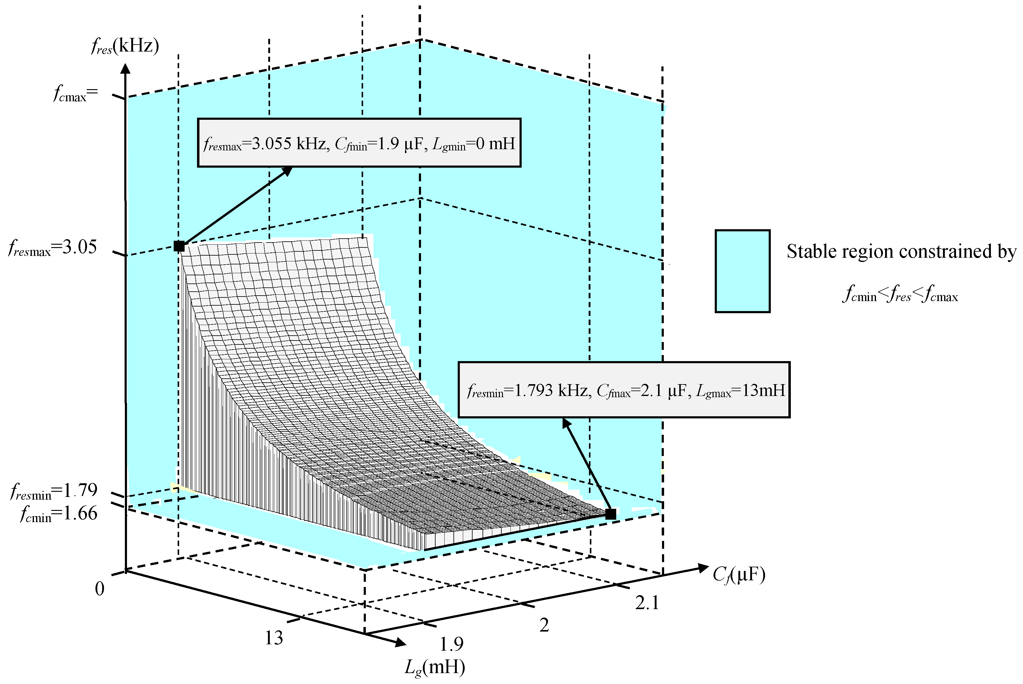
For long wires and weak grid conditions, the value of wires inductor is in the range of few mH. This value can be overestimated to 10 mH. The leakage inductance of the transformer is equal to 3 mH. Consequently, the grid inductor can reach a maximum value of 13 mH. While the value of the capacitor varies between 1.9 µF and 2.1 µF since the capacitor accuracy is equal to 5%. Note that, the minimum value fresmin is obtained for weak grid conditions (Lg = Lgmax = 13 mH) and maximum capacitor value (Cf = Cfmax), while the maximal value fresmax is obtained for stiff grid conditions (Lg = 0) and minimum capacitor value (Cf = Cfmin). Based on Equations (22) and (23), the desired harmonic attenuation rate must obey to conditions given by the following equations:
δ > 0.62 %
δ < 29.8 %
On the other hand, the harmonic attenuation rate δ must verify also Equation (27), which is deduced from Equation (24):
δ > δ min = 1.72 %
Based on Equations (26a), (26b) and (27), the harmonic attenuation rate δ must obey to the following condition:
1.72 % < δ < 29.8 %
A current harmonic attenuation rate δ of 7% is selected. Then a value of a = 0.4 is computed based on Equation (19b). According to Equation (18a), the value of grid side inductor is 2 mH which presents 16% of the total LCL filter inductor value.
-
Resonance frequency
For the considered 4 kW case study, conditions given by Equation (9) are verified as shown in the following equation:
10 f g = 500 Hz f c min = 1.667 kHz < f r e s min = 1.793 kHz f r e s f r e s max = 3.055 kHz < f c max = f s ω 2 = 5 kHz
Figure 6 shows the resonance frequency as a function of grid inductor variation and filter capacitor error for the obtained LCL filter inductors (Li = 5 mH and L2 = 2 mH). As it is shown in this figure, the range of resonance frequency variation is limited between fcmin and fcmax even for the worst case of Cf and Lg. Consequently, for the chosen LCL filter parameters and for the worst case of Lg and Cf, the resonance frequency is placed in a stable region where no damping is required.
Also, for the obtained LCL filter parameters, conditions given by Equations (25a) and (25b) are verified as shown in the following equation:
For   fundamental   signals :   Z C f = 1591 > >   Z L 2 = 0.628     Z C f 2500   Z L 2 For   high   frequencies :   Z C f = 7.95 < <   Z L 2 = 125.66     Z C f 0.05   Z L 2
Figure 7 presents the control strategy employed in this paper for regulating the grid-side currents i2(a,b,c). It is based on the voltage oriented PI control, which is designed in the dq synchronous reference frame. In this figure, idq and Vdq denote respectively the dq-axis current and voltage of dq transformation, while i* and V* denote respectively the reference current and voltage. Since the simplified block diagram of an LCL filter in the dq frame can be considered the same as in the abc frame (by neglecting the decoupling terms on d and q axis) [9], the open and closed loop transfer functions of the whole controlled system are given by Equations (31a) and (31b), respectively:
F O = i 2 d q i 2 d q i 2 d q = K p s + K i L i L 2 g C f s 4 + C f ( L 2 g R i + L i R 2 g ) s 3 + ( C f L 2 g R i + L i + L 2 g ) s 2 + ( R i + R 2 g ) s
F C = i 2 d q i 2 d q = K p s + K i L i L 2 g C f s 4 + C f ( L 2 g R i + L i R 2 g ) s 3 + ( C f L 2 g R i + L i + L 2 g ) s 2 + ( R i + R 2 g + K p ) s + K i
Table 1 shows the used system parameters. In this table, the PI controller parameters (Kp and Ki) (used for grid-side current regulation) were tuned according to the optimum criterion method [9].
In Figure 8 is reported the root locus of the FC transfer function (Equation (31b)) when Lg varies from 0 to 13 mH (with a step of 1 mH). As shown in this figure, the system stability is ensured without damping even for large grid impedance variation. Moreover, since the converter side inductor is realized using the iron-powder core with distributed air gap (Figure 13), its inductance value can change over the time. The robustness of the system against converter side inductor variations was investigated for the obtained filter parameters. To this purpose, Figure 9 shows the Bode diagram of the FO transfer function (Equation (31a)) when Li varies from 3.5 mH to 6.5 mH (5 mH ± 30%). According to this figure, for all cases of the Li variations, the gain margin Gm and phase margin Pm are larger than 19 dB and 45.9 degree, respectively. So, the system stability is ensured even for large converter side inductor variations.

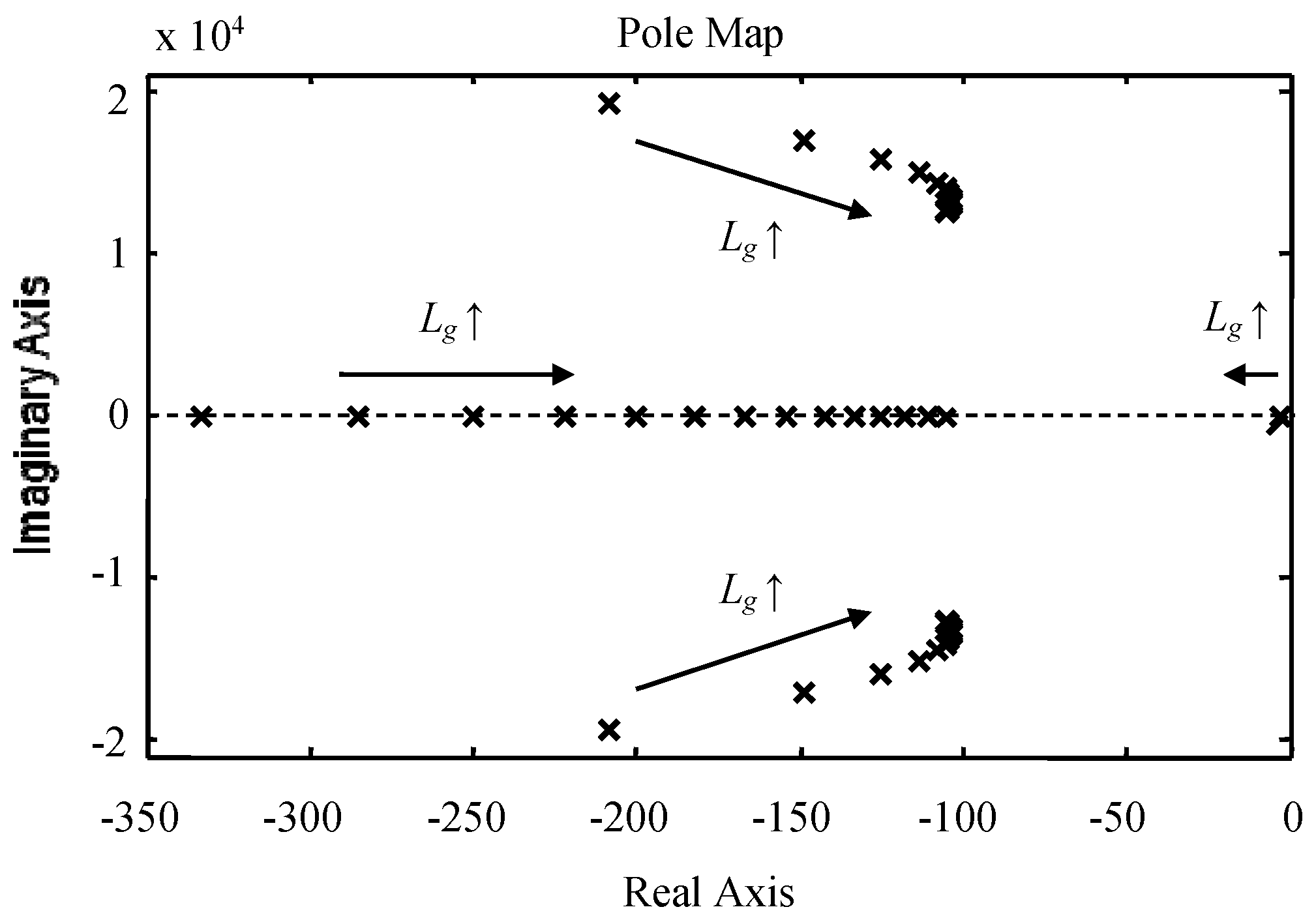
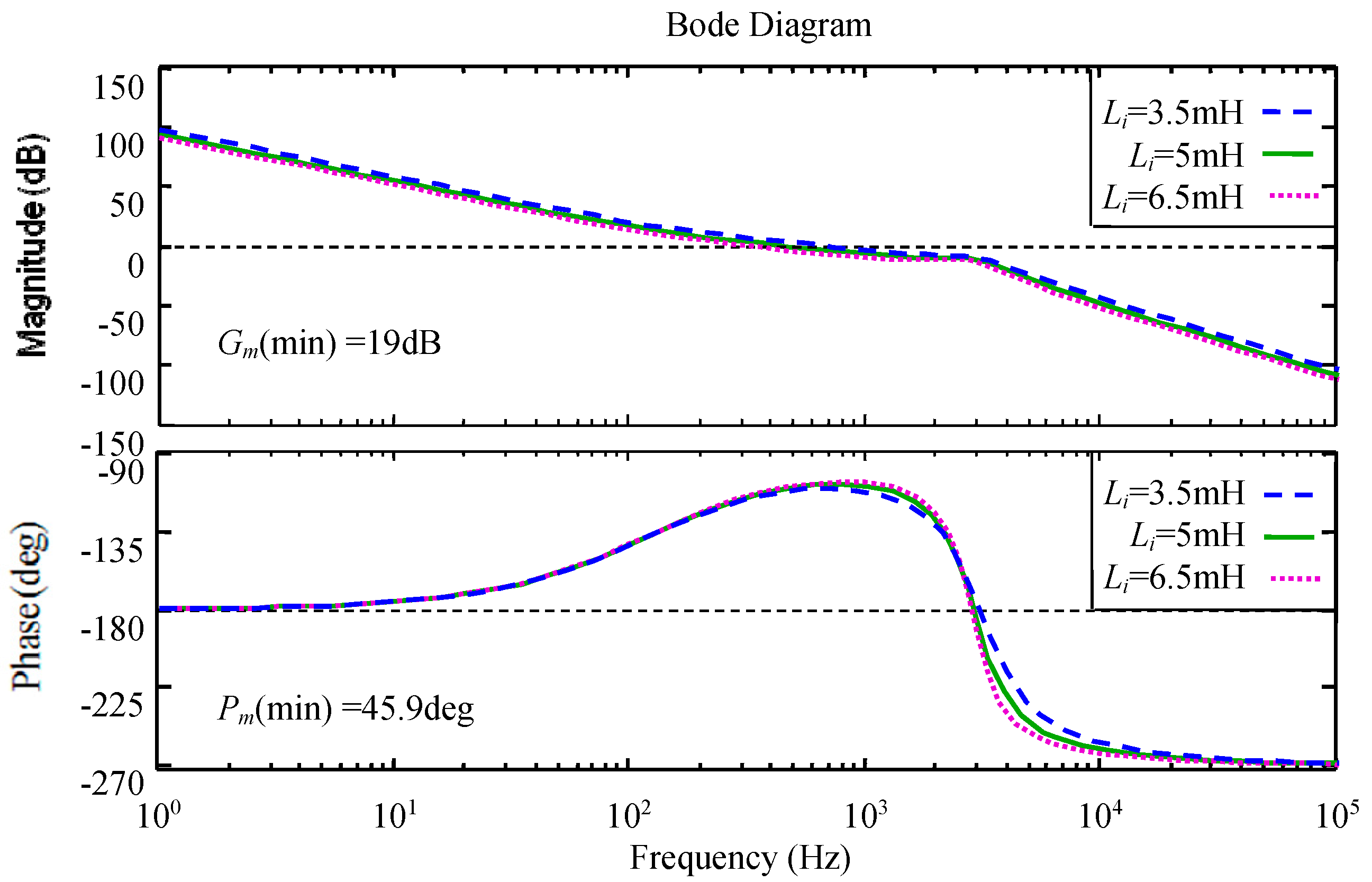
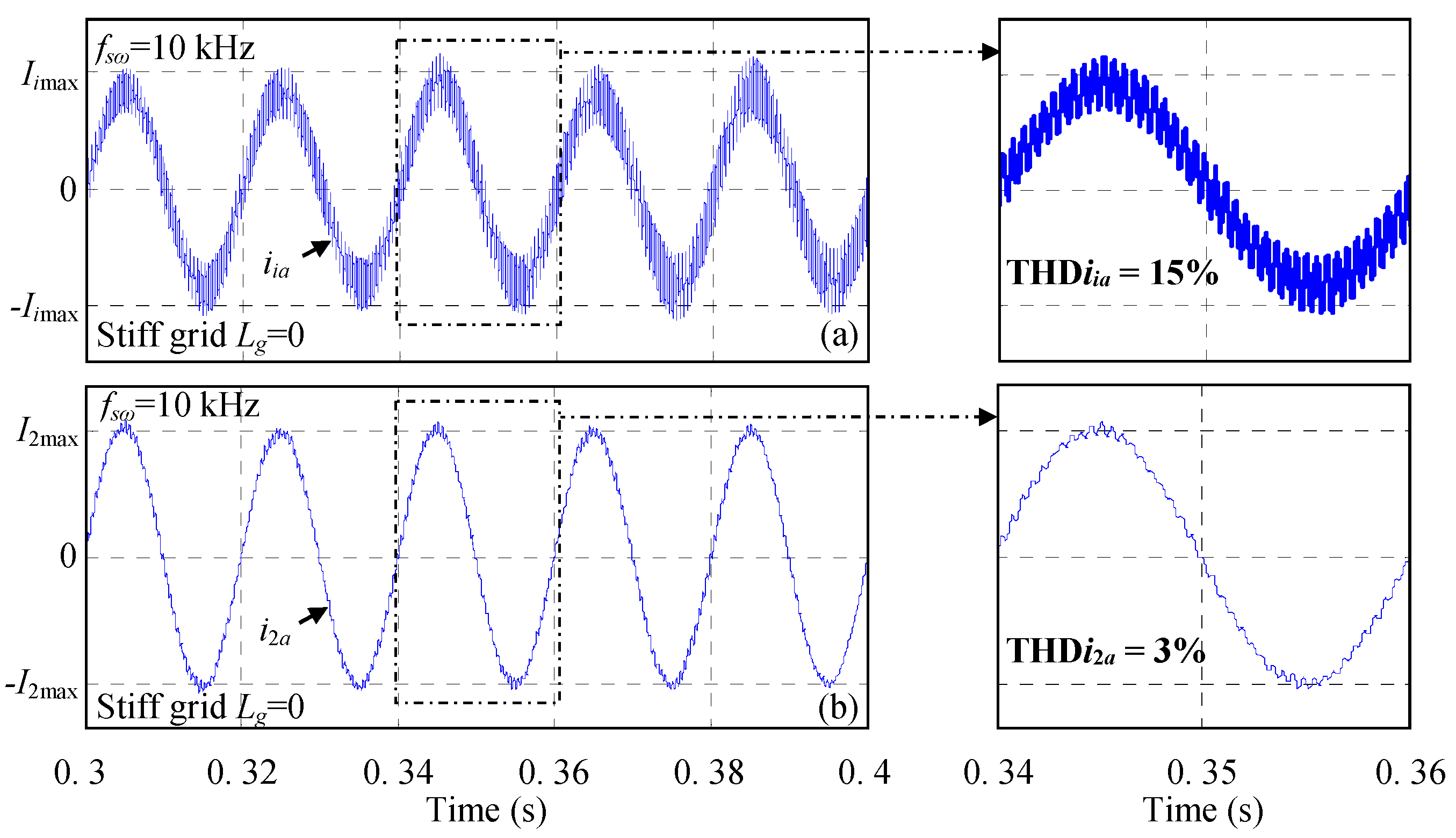
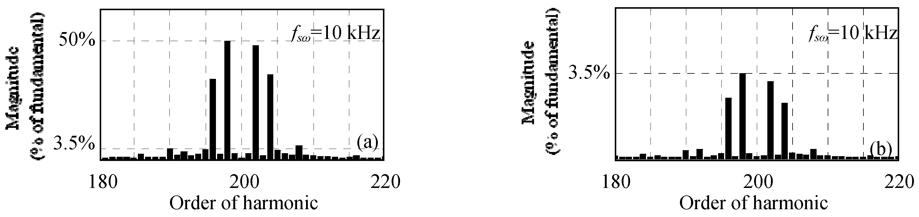
4.2. Simulation Results

The designed LCL filter is tested through simulation using a Matlab-Simulink software tool. The simulation results are obtained with a three-phase PWM rectifier, a switching frequency equal to 10 kHz and without the use of any damping method. Figure 10a,b show the simulation results of the converter current and grid current, respectively. It can be noted based on these figures that, using the designed LCL filter, the current harmonic components almost disappear at the switching frequency. The converter current THD is equal to 15%, while the grid current THD is equal to 3%. Hence, the THD in grid side has decreased and is well below 5% which meets the IEEE 519-1992 standard. It should be noted also, based on these figures, that the system is well stable without the use of any damping method. Figure 11a,b present the high frequency spectra of the simulated converter and grid currents, respectively. Based on these figures, the largest near switching frequency current harmonic component is equal to 50% on the converter side and 3.5% on the grid side. Thus, the harmonic attenuation rate δ, which is the ratio between the largest near switching frequency current harmonic component in the grid side and the one in the converter side, is well equal to 7%. Figure 12a shows the waveform of the grid current i2a with regard to the grid voltage Vga during steady state operation. It is commented that the grid current and the grid voltage are in phase. Hence, the power factor is close to the unity, which corresponds to grid code requirements. In order to test the robustness of the designed LCL filter, additional inductors of 13 mH are inserted in series with the filter grid side inductor. Figure 12b shows the simulation results of the grid current in case of weak grid conditions (Lg = 13 mH). It should be noted that the system remains stable without damping despite of a large variation of the grid inductor value. The obtained simulation results show that, even without damping, the system stability is guaranteed under stiff as well as weak grid conditions. Finally, it should be noted that the obtained LCL filter parameters are relatively small (Table 1) which can not only save money, but also enhance the dynamic response of the system. Simulation results indicate the effectiveness and the robustness of the designed LCL filter and therefore the efficiency of the proposed design methodology.

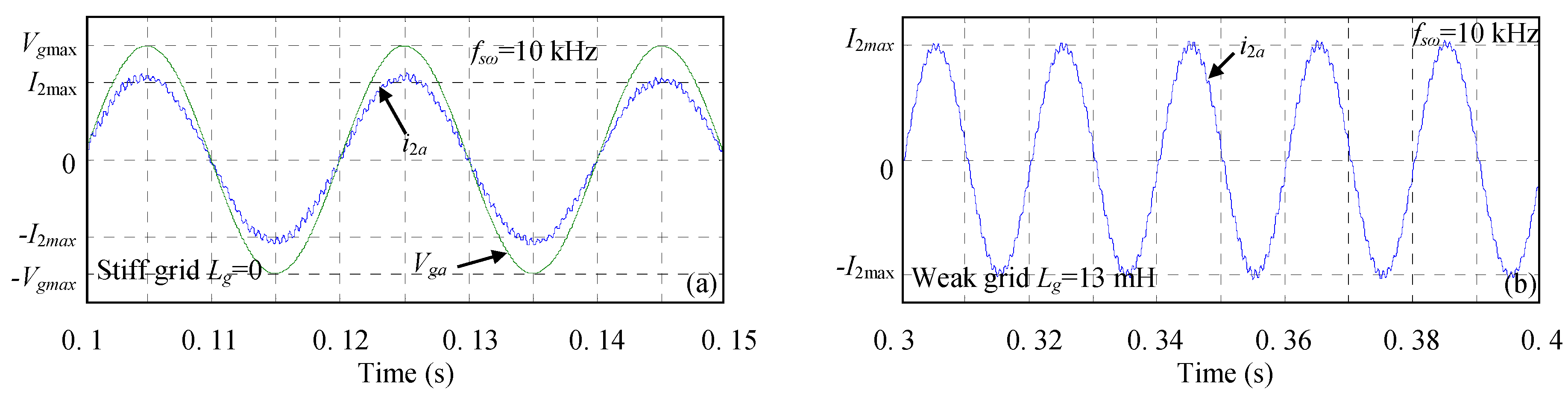
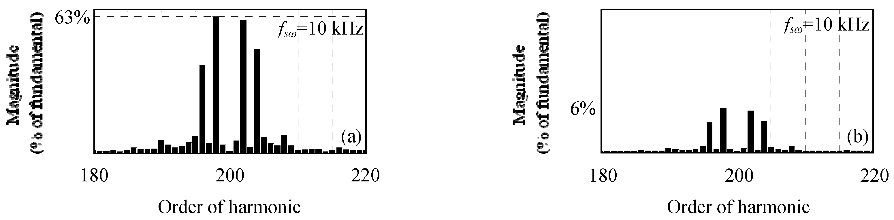
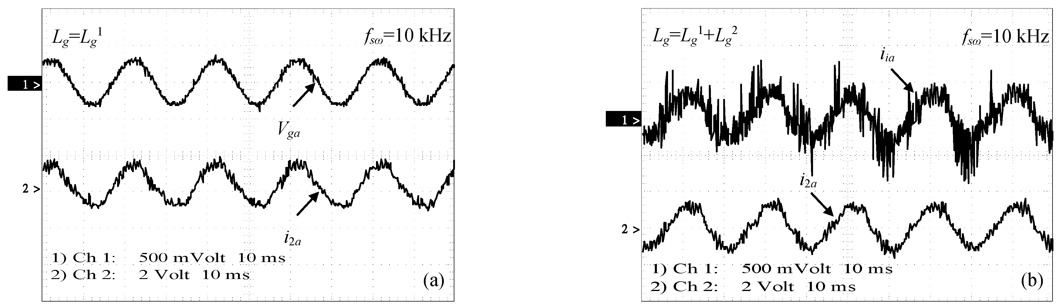
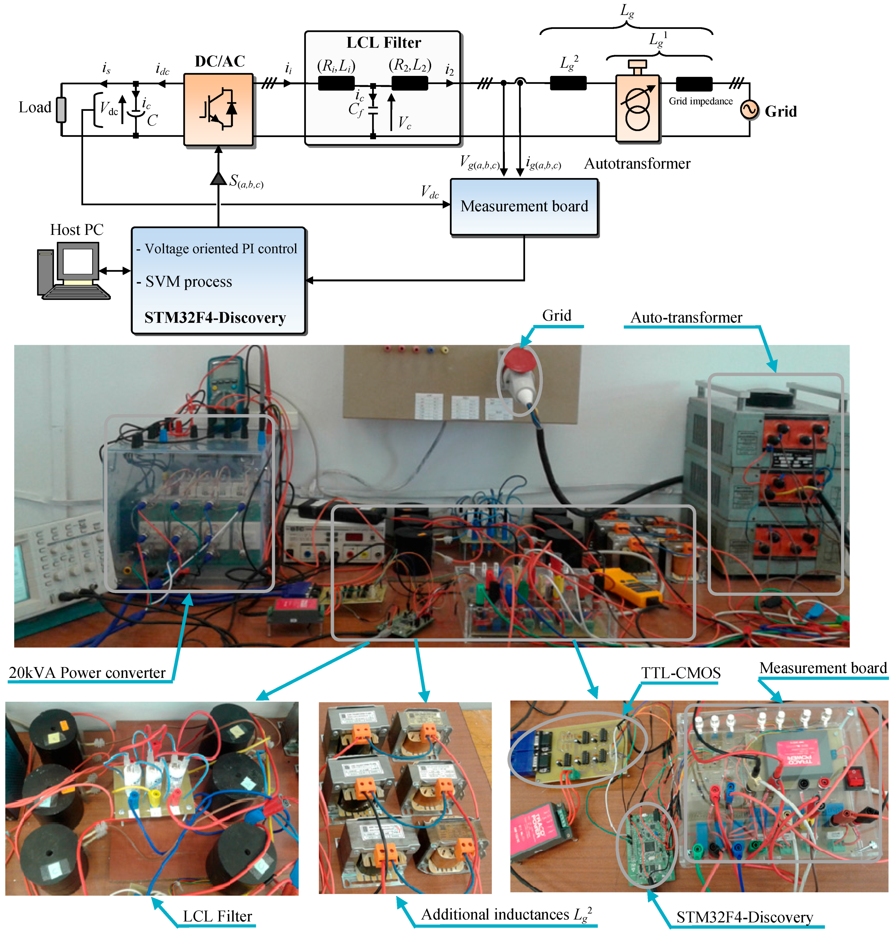
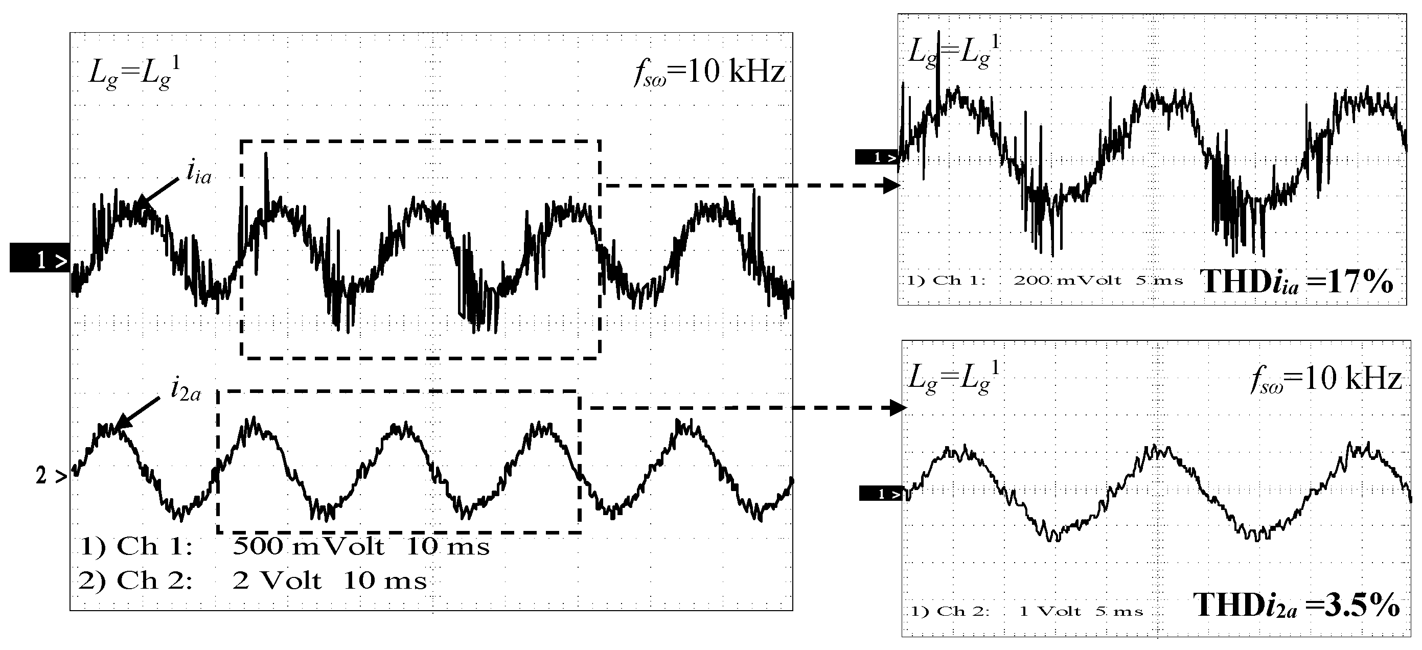
5. Experimental Results

In order to illustrate performances and effectiveness of the considered design methodology, the designed LCL filter was tested for connecting a three-phase PWM rectifier to the grid. The used experimental set-up is composed of:
-
A 20 kVA three phase high voltage power converter.
-
An auto transformer that varies the voltage peak magnitude (in the AC side).
-
An LCL filter (composed of three inductors (5 mH/10 A) with an internal resistor of 0.1 Ω, three capacitors (2 µF/400 V) and three inductors (2 mH/10 A) with an internal resistor of 0.1 Ω).
-
A capacitor for the dc-link (1100 μF/800 V).
-
Measurement board that provides current and voltage measurements.
-
Three inductors (4.5 mH/10 A) used in order to emulate the large grid impedance variation.
-
The STM32F4-Discovery digital solution, which is used for the implementation of the control algorithm.
The developed experimental set-up is presented in Figure 13. During experimental tests, the switching frequency was set to 10 kHz and the dc-link reference voltage V d c * was imposed equal to 150 V. Also, it should be noted that the experimental results were obtained without the use of any damping method. Moreover, in addition to the real grid inductance L g 1 that includes inductance of distribution wires and the one of the auto-transformer used during experimental tests, an additional inductance L g 2 equal to 4.5 mH was added in series with the LCL filter as shown in Figure 13. Figure 14 shows the waveforms of the converter current iia and the grid current i2a for Lg = L g 1 . The converter current THD is equal to 17%, while the grid current THD is equal to 3.5%. As depicted in Figure 14, the current harmonics and the THD value are reduced using the designed LCL filter. Moreover, the obtained grid current THD is below 5% which meets grid code requirements. Also, the stable operation of the system is ensured without the use of any damping method. Figure 15a,b present the high frequency spectra of the measured converter and grid currents. Based on these figures the largest near switching frequency current harmonic component is equal to 63% on the converter side and 6% on the grid side. Thus, the harmonic attenuation rate δ is equal to 10%.
Figure 16a presents the waveforms of the grid voltage Vga with regard to the grid current i2a during steady state operation. The power factor is close to the unity since the grid current and voltage are in phase. Figure 16b shows the waveforms of the converter current iia and the grid current i2a for Lg = L g 1 + L g 2 . It should be noted, based on this figure, that the stable operation of the system is ensued without damping despite of the large grid impedance variation. Moreover, it can be noted from experimental results that some low-frequency harmonics appear in the measured grid current. However, these odd harmonics could be neglected since they come from sensors noise and the external control loop of the dc-link voltage Vdc [40]. Finally, it is worth noting that the designed LCL filter provides high filtering performances with minimized size, weight, losses and cost. Also the obtained experimental results are quite closely similar to those obtained in simulation. Finally, it should be noted that experimental results indicate the high filtering performances and reliability of the designed LCL filter and therefore the efficiency of the proposed design methodology.

6. Conclusions

This paper proposes a simple, robust and systematic design methodology for an LCL filter, used to interface between three phase power converter and the utility grid. This filter is used in order to reduce the switching frequency current harmonics produced by the power converter. The proposed design methodology is simple, efficient and aimed to meet the grid code requirements. Compared to classical design methodologies, the considered one allows the achievement of robust LCL filter design with regard to large grid impedance variations without damping when the grid current is the used feedback variable. Moreover, it takes into account accuracy of capacitor standard values and proposes a simple design method for the converter side inductor that avoids saturation problems. An example of LCL filter design is presented and discussed. The obtained filter parameters were tested using Matlab-Simulink software tool and through the development of an experimental set-up. The obtained simulation and experimental results show the reliability, efficiency and high filtering performances of the proposed design methodology. It should be noted that, although the system stability is guaranteed without damping by the proposed LCL design methodology, the stable region is small, and the resonance phenomenon must be considered. For further work, the robustness of the system can be improved by adding active damping methods.

Acknowledgments

We would like to thank all reviewers for their valuable comments, helpful suggestions and their careful review, which helped to improve the quality of the paper. “This work was supported by the Tunisian Ministry of High Education and Research under Grant LSE-ENIT-LR11ES15”.

Author Contributions

Marwa Ben Said-Romdhane developed the proposed LCL filter design methodology and validated it through simulation results using Matlab-Simulink® and experimental results using a prototyping platform. The others co-authors contributed by supervising the research work and by providing facilities.

Conflicts of Interest

The authors declare no conflicts of interest.

References

  1. Liserre, M.; Sauter, T.; Hung, J.Y. Future energy systems: Integrating renewable energy sources into the smart power grid through industrial electronics. IEEE Trans. Ind. Electron. Mag. 2010, 4, 18–37. [Google Scholar] [CrossRef]
  2. Roy, N.K.; Pota, H.R. Current status and issues of concern for the integration of distributed generation into electricity networks. IEEE Syst. J. 2015, 9, 933–944. [Google Scholar] [CrossRef]
  3. Tsili, M.; Papathanassiou, S. A review of grid code technical requirements for wind farms. IET Renew. Power Gener. 2009, 3, 308–332. [Google Scholar] [CrossRef]
  4. Cracium, B.I.; Kerekes, T.; Sera, D.; Teodorescu, R. Overview of recent grid codes for PV power integration. In Proceedings of the 13th International Conference on Optimization of Electrical and Electronic Equipment (OPTIM), Brasov, Romania, 24–26 May 2012; pp. 959–965.
  5. Lettl, J.; Bauer, J.; Linhart, L. Comparison of different filter types for grid connected inverter. In Proceedings of the 29th Progress in Electromagnetics Research Symposium (PIERS 2011), Marrakesh, Morocco, 20–23 March 2011; pp. 1426–1429.
  6. Elsaharty, M.A.; Ashour, H.A. Passive L and LCL filter design method for grid-connected inverters. In Proceedings of the 2014 IEEE Conference in Innovative Smart Grid Technologies, Kuala Lumpur, Malaysia, 20–23 May 2014; pp. 13–18.
  7. Fu, X.; Li, S. A Novel Neural Network Vector Control for Single-Phase Grid-Connected Converters with L, LC and LCL Filters. Energies 2016, 9, 328. [Google Scholar] [CrossRef]
  8. Cao, W.; Liu, K.; Ji, Y.; Wang, Y.; Zhao, J. Design of a Four-Branch LCL-Type Grid-Connecting Interface for a Three-Phase, Four-Leg Active Power Filter. Energies 2015, 8, 1606–1627. [Google Scholar] [CrossRef]
  9. Liserre, M.; Blaabjerg, F.; Hansen, S. Design and control of an LCL-filter-based three-phase active rectifier. IEEE Trans. Ind. Appl. 2005, 41, 1281–1291. [Google Scholar] [CrossRef]
  10. Popescu, M.; Bitoleanu, A.; Preda, A. A new design method of an LCL filter in active dc-traction substations. In Proceedings of the 2016 IEEE International Power Electronics and Motion Control Conference, Varna, Bulgaria, 25–28 September 2016; pp. 876–881.
  11. Park, M.; Chi, M.; Park, J.; Kim, H.; Chun, T.; Nho, E. LCL-filter design for grid connected PCS using total harmonic distortion and ripple attenuation factor. In Proceedings of the 2010 IEEE International Conference on Power Electronics Conference, Sapporo, Japan, 21–24 June 2010; pp. 1688–1694.
  12. Wu, Z.; Aldeen, M.; Saha, S. A novel optimization method for the design of LCL filters for three-phase grid-tied inverters. In Proceedings of the 2016 IEEE Innovative Smart Grid Technologies, Melbourne, Australia, 28 November–1 December 2016; pp. 214–220.
  13. Tang, Y.; Yao, W.; Loh, P.C.; Blaabjerg, F. Design of LCL filters with LCL resonance frequencies beyond the nyquist frequency for grid-connected converters. IEEE J. Emerg. Sel. Top. Power Electron. 2016, 4, 3–14. [Google Scholar] [CrossRef]
  14. Yanga, J.; Lee, F.C. LCL filter design and inductor current ripple analysis for a three-level NPC grid interface converter. IEEE Trans. Power. Electron. 2015, 30, 4659–4668. [Google Scholar]
  15. Jayalath, S.; Hanif, M. Generalized LCL-Filer Design Algorithm for Grid-connected Voltage Source Inverter. IEEE Trans. Ind. Electron. 2017, 64, 1905–1915. [Google Scholar] [CrossRef]
  16. Park, K.B.; Kieferndorf, F.; Drofenik, U.; Pettersson, S.; Canales, F. Weight Minimization of LCL Filters for High Power Converters. IEEE Trans. Ind. Appl. 2017. [Google Scholar] [CrossRef]
  17. Pan, D.; Ruan, X.; Bao, C.; Li, W.; Wang, X. Optimized controller design for LCL-type grid-connected inverter to achieve high robustness against grid-impedance variation. IEEE Trans. Ind. Electron. 2014, 62, 1537–1547. [Google Scholar] [CrossRef]
  18. Klaus, H.; Klaus-Dieter, D. Elektrische Engergieversorgung, 3rd ed.; Vieweg: Braunschweig, Germany, 2010. [Google Scholar]
  19. Xu, J.; Xie, S.; Tang, T. Improved control strategy with grid-voltage feedforward for LCL-filter-based inverter connected to weak grid. IET Power Electron. 2014, 7, 2660–2671. [Google Scholar] [CrossRef]
  20. He, J.; Wei Li, Y.; Bosnjak, D.; Harris, B. Investigation and active damping of multiple resonances in a parallel-inverter-based microgrid. IEEE Trans. Power Electron. 2012, 28, 234–246. [Google Scholar] [CrossRef]
  21. Cehn, C.; Xiong, J.; Lei, J.; Zhang, K. Time delay compensation method based on area equivalence for active damping of LCL-type converter. IEEE Trans. Power Electron. 2016, 32, 762–772. [Google Scholar]
  22. Wang, X.; Blaabjerg, F.; Chiang Loh, P. Grid-current-feedback active damping for LCL resonance in grid-connected voltage-source converters. IEEE Trans. Power Electron. 2016, 31, 213–223. [Google Scholar] [CrossRef]
  23. Yao, W.; Yang, Y.; Xiaobin, Z.; Blaabjerg, F.; Loh, P.C. Design and Analysis of Robust Active Damping for LCL Filters Using Digital Notch Filters. IEEE Trans. Power Electron. 2017, 32, 2360–2375. [Google Scholar] [CrossRef]
  24. Ben Said-Romdhane, M.; Naouar, M.W.; Slama-Blkhodja, I.; Monmasson, E. Robust Active Damping Methods for LCL Filter Based Grid Connected Converters. IEEE Trans. Power Electron. 2016. [Google Scholar] [CrossRef]
  25. Lorzadeh, I.; AskarianAbyaneh, H.; Savaghebi, M.; Bakhshai, A.; Guerrero, J.M. Capacitor Current Feedback-Based Active Resonance Damping Strategies for Digitally-Controlled Inductive-Capacitive-Inductive-Filtered Grid-Connected Inverters. Energies 2017, 9, 642. [Google Scholar] [CrossRef]
  26. Xin, Z.; Ching, P.; Wang, X.; Blaabjerg, F.; Tang, Y. Highly accurate derivatives for LCL-filtered grid converter with capacitor voltage active damping. IEEE Trans. Power Electron. 2016, 31, 3612–3625. [Google Scholar] [CrossRef]
  27. Hyo-Min, A.; Chang-Yeol, O.; Won-Yong, S.; Jung-Hoon, A.; Byoung-Kuk, L. Analysis and design of LCL filter with passive damping circuits for three-phase grid-connected inverters. In Proceedings of the 9th International Conference on Power Electronics and ECCE Asia (ICPE-ECCE Asia), Seoul, Korea, 1–5 June 2015; pp. 652–658.
  28. Xiongfei, W.; Beres, R.; Blaabjerg, F.; Poh, C. Passivity-based design of passive damping for LCL-filtered voltage source converters. In Proceedings of the 2015 IEEE Energy Conversion Congress and Exposition, Montreal, QC, Canada, 20–24 September 2015; pp. 3718–3725.
  29. Beres, R.N.; Wang, X.; Blaabjerg, F.; Liserre, M.; Bak, C.L. Optimal Design of High-Order Passive-Damped Filters for Grid-Connected Applications. IEEE Trans. Power Electron. 2016, 31, 2083–2098. [Google Scholar] [CrossRef]
  30. Beres, R.N.; Wang, X.; Blaaberj, F.; Liserre, M.; Bak, C.L. Optimal design of High-order passive-damped filters for grid-connected applications. IEEE Trans. Power Electron. 2016, 31, 2083–2098. [Google Scholar] [CrossRef]
  31. Parker, S.G.; McGrath, B.P.; Holmes, D.G. Regions of active damping control for LCL filters. IEEE Trans. Ind. Appl. 2014, 50, 424–432. [Google Scholar] [CrossRef]
  32. Yi, T.; Changwoo, Y.; Rongwu, Z.; Blaabjerg, F. Generalized stability regions of current control for LCL-filtered grid-connected converters without passive or active damping. In Proceedings of the 2015 IEEE Energy Conversion Congress and Exposition, Montreal, QC, Canada, 20–24 September 2015; pp. 2040–2047.
  33. Jianguo, W.; Jiu, D.Y.; Lin, J.; Jiyan, Z. Delay-dependent stability of single-loop controlled grid-connected inverters with LCL filters. IEEE Trans. Power Electron. 2016, 31, 743–757. [Google Scholar]
  34. Gohil, G.; Bede, L.; Teodorescu, R.; Kerekes, T.; Blaabjerg, F. Line Filter Design of Parallel Inverleaved VSCs for High-Power Wind Energy Conversion Systems. IEEE Trans. Power Electron. 2015, 30, 6775–6790. [Google Scholar] [CrossRef]
  35. Rockhill, A.A.; Liserre, M.; Teodorescu, R.; Rodriguez, P. Grid-Filter Design for a Multimegawatt Medium-Voltage Voltage-Source Inverter. IEEE Trans. Power Electron. 2011, 58, 1205–1216. [Google Scholar] [CrossRef] [Green Version]
  36. Ben Said-Romdhane, M.; Naouar, M.W.; Slama.Belkhodja, I.; Monmasson, E. Simple and systematic LCL filter design for three-phase grid-connected power converters. Math. Comput. Simul. 2016, 130, 181–193. [Google Scholar] [CrossRef]
  37. Ren, B.; Sun, X.; An, S.; Cao, X.; Zhang, Q. Analysis and Design of an LCL Filter for the Three-level Grid-connected Inverter. In Proceedings of the 7th International Conference on Power Electronics and Motion Control, Harbin, China, 2–5 June 2012; pp. 2023–2027.
  38. Sanatkar-Chayjani, M.; Monfared, M. Design of LCL and LLCL filters for single-phase grid connected converters. IET Power Electron. 2016, 9, 1971–1978. [Google Scholar] [CrossRef]
  39. 519-1992-IEEE Recommended Practices and Requirements for Harmonic Control in Electrical Power Systems; The Institute of Electrical and Electronics Engineers Inc.: New York, NY, USA, 1993.
  40. Karimi-Ghartemani, M.; Khajehoddin, S.A.; Jain, P.; Bakhshai, A. A systematic approach to DC-Bus control design in single-phase grid-connected renewable converters. IEEE Trans. Power Electron. 2013, 28, 3158–3166. [Google Scholar] [CrossRef]
Figure 1. (a) Power circuit of the three phase grid connected power converter with LCL filter; (b) single phase equivalent circuit; (c) block diagram of the LCL filter.
Energies 10 00336 g001
Figure 2. Single phase equivalent circuit with LCL filter at the n-harmonic.
Energies 10 00336 g002
Figure 3. Fresnel diagram characterizing the operation of the LCL filter.
Energies 10 00336 g003
Figure 4. Evolution of the converter current ii and voltage Vi.
Energies 10 00336 g004
Figure 5. LCL filter design algorithm.
Energies 10 00336 g005
Figure 6. Resonance frequency according to grid inductor and filter capacitor accuracy.
Energies 10 00336 g006
Figure 7. Voltage oriented PI control structure for LCL-filter-based Grid-connected Converters.
Energies 10 00336 g007
Figure 8. Pole map of the closed-loop system when Lg varies from 0 to 13 mH.
Energies 10 00336 g008
Figure 9. Bode diagram of the open loop system when Li varies from 3.5 mH to 6.5 mH (5 mH ± 30%).
Energies 10 00336 g009
Figure 10. Simulation results during steady state operation (a) power converter current iia response; (b) grid current i2a response.
Energies 10 00336 g010
Figure 11. High frequency spectra of (a) power converter current; (b) grid current.
Energies 10 00336 g011
Figure 12. Simulation results during steady state operation (a) grid voltage Vga and current i2a waveforms (b) grid current i2a response for Lg = 13 mH.
Energies 10 00336 g012
Figure 13. Experimental set-up.
Energies 10 00336 g013
Figure 14. Measured power converter current iia (1 A/100 mV) and grid current i2a (1 A/100 mV) for Lg = L g 1 .
Energies 10 00336 g014
Figure 15. High frequency spectra of (a) power converter current (b) grid current.
Energies 10 00336 g015
Figure 16. (a) Grid voltage Vga (50 V/100 mV) and current i2a (1 A/100 mV) waveforms at steady state operation; (b) measured power converter current iia (1 A/100 mV) and grid current i2a (1 A/100 mV) for Lg = L g 1 + L g 2 .
Energies 10 00336 g016
Table 1. System parameters.
ParameterValue
SystemUg400 V
P4 kW
f10 kHz
fg50 Hz
Vdc600 V
LCL filterCf2 µF
Li5 mH
L22 mH
PI controllerKp2.4
Ki592
Grid inductanceLgLgmin = 0 mH and Lgmax = 13 mH

