Article

Electric Field Simulations and Analysis for High Voltage High Power Medium Frequency Transformer

1
State Key Laboratory of Advanced Electromagnetic Engineering and Technology, Huazhong University of Science and Technology, 1037 Luoyu Road, Wuhan 430074, China
2
School of Electrical & Electronic Engineering, Huazhong University of Science and Technology, 1037 Luoyu Road, Wuhan 430074, China
*
Author to whom correspondence should be addressed.
Energies 2017, 10(3), 371; https://doi.org/10.3390/en10030371
Submission received: 26 December 2016 / Revised: 5 March 2017 / Accepted: 10 March 2017 / Published: 16 March 2017
(This article belongs to the Collection Smart Grid)

Abstract

:
The electronic power transformer (EPT) raises concerns for its notable size and volume reduction compared with traditional line frequency transformers. Medium frequency transformers (MFTs) are important components in high voltage and high power energy conversion systems such as EPTs. High voltage and high power make the reliable insulation design of MFT more difficult. In this paper, the influence of wire type and interleaved winding structure on the electric field distribution of MFT is discussed in detail. The electric field distributions for six kinds of typical non-interleaved windings with different wire types are researched using a 2-D finite element method (FEM). The electric field distributions for one non-interleaved winding and two interleaved windings are also studied using 2-D FEM. Furthermore, the maximum electric field intensities are obtained and compared. The results show that, in this case study, compared with foil conductor, smaller maximum electric field intensity can be achieved using litz wire in secondary winding. Besides, interleaving can increase the maximum electric field intensity when insulation distance is constant. The proposed method of studying the electric field distribution and analysis results are expected to make a contribution to the improvement of electric field distribution in transformers.

1. Introduction

Medium frequency transformers (MFTs) are usually critical elements in high voltage, high power energy conversion systems, including electronic power transformer (EPT) [1,2], solid state transformers (SST) [3], power electronic transformers (PET) [4], and power electronic traction transformers (PETT) [5]. These energy conversion systems are especially suitable for converters of power systems, wind farms [1], and traction converters, and they are expected to play an important role in future smart grid.
Previous works regarding MFT can be found in literatures [6,7,8,9,10,11]. Literature [6] presents an improved thermal model for multi-layer winding consisting of litz-wire and the analytical calculation of maximum electric field strength in the core window area. Literature [7] proposes a design methodology of medium-frequency power transformer that accounts for a tuned leakage inductance of the transformer, core and winding losses mitigation, thermal management, and high isolation requirements. In literature [8], two optimized transformer concepts, differing in their core material and cooling strategies, are constructed, aiming for different power density/efficiency goals, and the author proposes that the research on the effectiveness of the utilized isolation strategies concerning long term operation and different operation conditions should be addressed in order to make the SST technology an attractive replacement for line frequency transformers [8]. Literature [9] provides a step-by-step design for MFTs with high isolation requirement, and the required design considerations, including isolation and thermal management, are explained in detail. In literature [10], the inductance optimization is studied, and a high voltage insulation is carefully designed to support 15 kV for SST application. Literature [11] analyzes the voltage stress appearing in cascaded converters, in time and frequency domains. The simulations of the electric field distributions in these transformer are presented, and the impact of the converter topology on the insulation stress is highlighted. The highest electric fields appear in the MFT of the converter cells’ dc-dc converters, which provide galvanic isolation within the SST [11]. Durable insulation is especially important for high power high voltage transformers since high electric stress leads to partial discharge and the breakdown of transformers [12], and the breakdown of transformers usually leads to costly repair or replacement [13].
The concentrated research on electric field distribution and insulation design of transformers can be found in literatures [12,14,15,16,17,18]. Literature [12] focuses on the transient electric field characteristics in oil-pressboard composite insulation under voltage polarity reversal. The research adopted the Kerr electro-optic effect technique to conduct real-time measurement of the oil electric fields at the polarity reversal time of 10, 60, and 120 s respectively, and several important research results are provided. Literature [14] presents a study of the parameters that affect the breakdown voltage in the insulation supports of a standard dip and bake dry-type transformer. Besides, the modifications to the design of currently used insulating support are estimated to reduce its length without increasing the possibility of breakdown. In literature [15], a lumped parameter equivalent model is developed by dividing transformer windings into several blocks, then a 2-D asymmetrical electric field finite-element analysis is performed to determine electric fields through the windings. Literature [16] presents a detailed analysis of both near and far stray magnetic fields of dry type distribution transformers, and the results of 3-D simulations are compared with the measurements and show good accuracy, allowing for design to be based on simulations. Literature [17] deals with the design improvements on graded insulation of power transformers using transient electric field analysis and a visualization technique. Literature [18] considers the algorithm of design for an insulation system of a high-voltage combined instrument transformer using the field method. The author’s software SHIELDS was used to optimize the number, dimensions, and position of each electrostatic control shield in the insulation of the voltage and current parts.
The contributions of this paper include: (1) The influence of wire type on electric field distribution of MFT is discussed in detail, which has not been studied by previous researchers. Three kinds of wire types are widely used in MFTs, including litz wire, foil conductor and flat copper wire. The electric field distributions of six kinds of non-interleaved windings using different wire types are researched and compared using 2-D finite element method (FEM) [19]. (2) The influence of interleaved winding structure on electric field distribution of MFT is discussed in detail, which has not been researched in previous works. Interleaved winding structure can reduce the leakage inductance of transformers, and it has been widely adopted in transformer design [20]. The electric field distributions for two kinds of interleaved windings and one non-interleaved winding are studied and compared using 2-D FEM. The proposed method of studying the electric field distribution and analysis results are expected to make a contribution to the improvement of electric field distribution in transformers. Though the proposed method is applied to MFT in this paper, the method is general and it is also applicable for power transformers.
The case study in this paper is performed based on a 1.5 kV, 35 kW, 1 kHz core-type MFT used in a subunit of 10 kV EPT [21]. EPT is a new type of power transformer. Some new functions can be obtained by EPT, including providing high quality electric energy to the consumer and improving the dynamic performance of the power grid [2]. The main circuit structure of the 10 kV EPT can be found in [2]. The harmonic content and efficiency are two important indicators for EPT. The switching losses increase and the efficiency decreases with increasing switching frequency. The 1 kHz switching frequency is adopted since it can fulfill the design requirement of harmonic content for high voltage high power EPT, and desirable efficiency can be achieved. Therefore, the switching frequency for the MFT is 1 kHz. The MFT works in a dc-dc converter as shown in Figure 1, and the working voltage of this MFT is 1 kHz square wave with low frequency ripple.
This paper is organized as follow: Section 2 introduces the FEM model of the MFT. Section 3 presents the six kinds of typical non-interleaved windings with different wire types and their electric field distribution results using 2-D FEM. Section 4 presents one non-interleaved winding and two interleaved windings and their electric field distribution results using 2-D FEM. Finally, in Section 5, the suggestions on insulation design of MFT are provided based on the FEM results and discussion in Section 3 and Section 4.

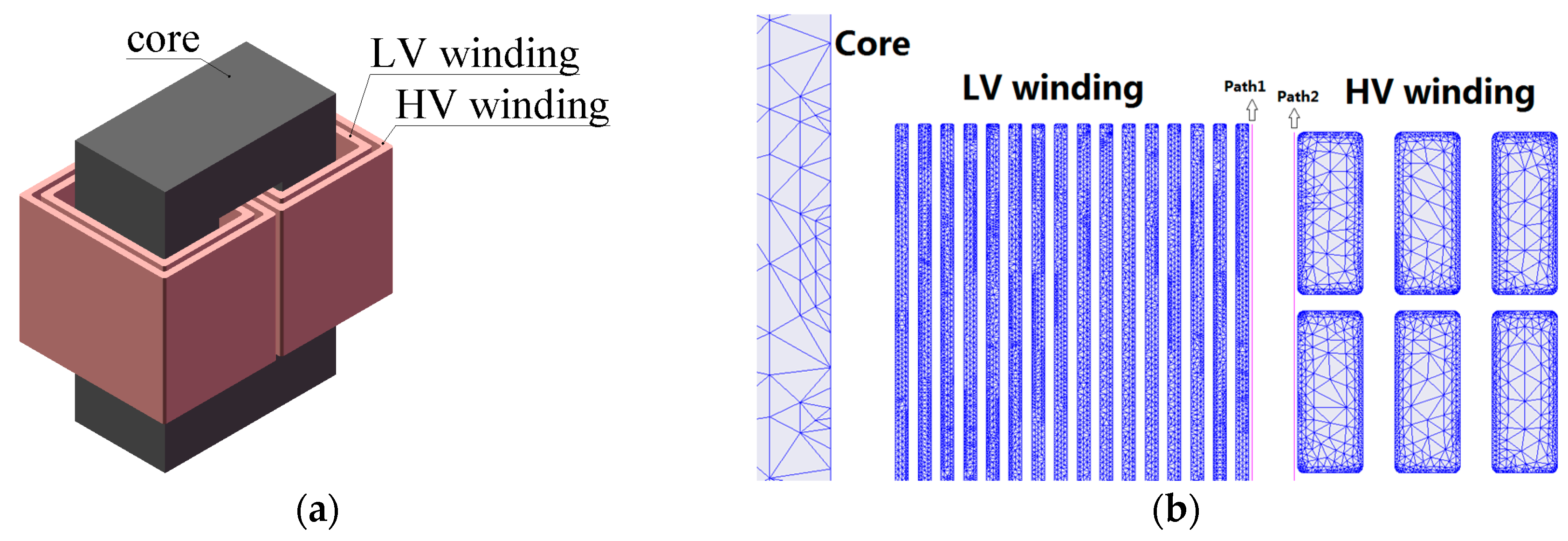
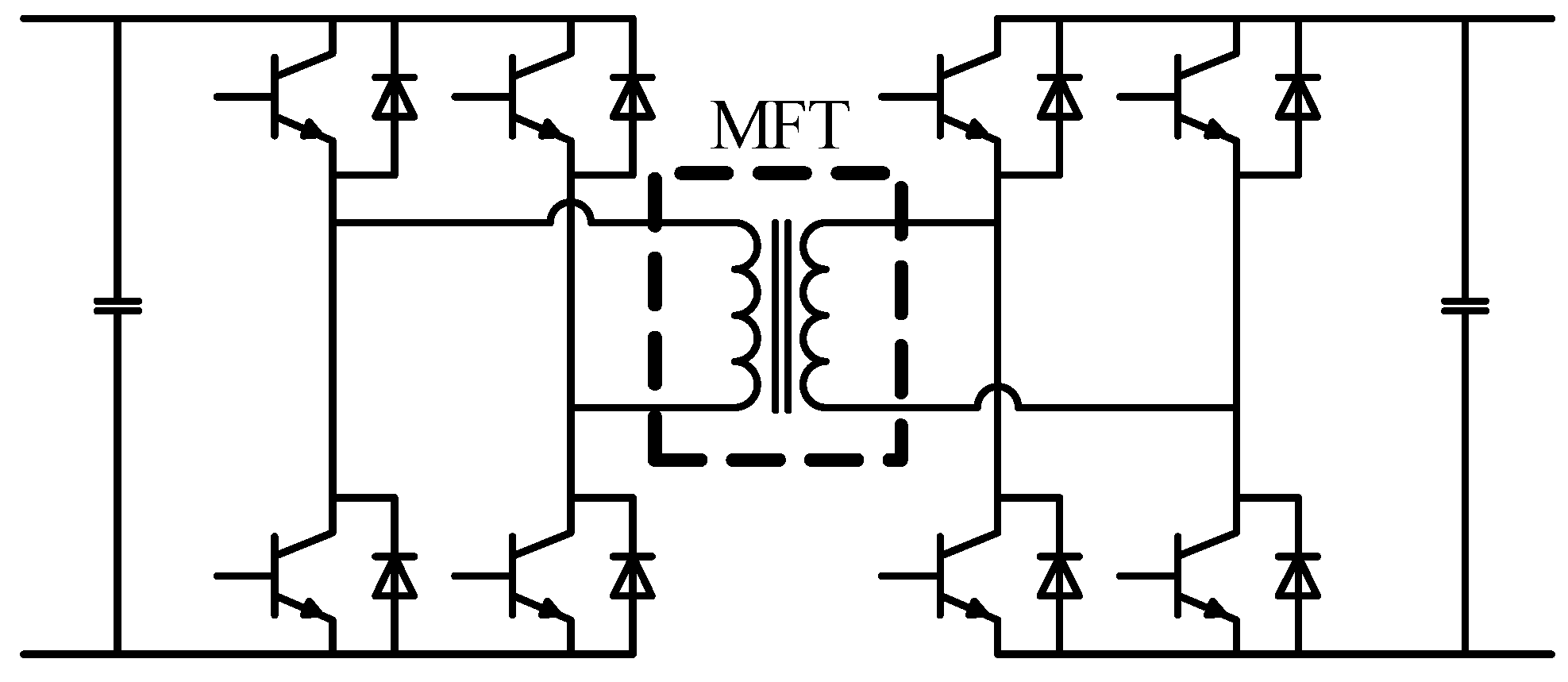
2. Finite Element Modeling of MFT

2-D finite element method (FEM) is adopted to obtain the electric field distribution of MFT in this paper, using the finite element simulation software ANSYS (Maxwell 16.0, ANSYS, Pittsburgh, PA, USA). The case study is performed based on a 35 kW MFT used in a 10 kV EPT. The maximum working voltage of this EPT is 10 kV, thus, the target insulation voltage for this MFT is 10 kV, and safety factor [7] should be considered when determining the insulation distance. The structure of the core type MFT is shown in Figure 2a. The 2-D electrostatic finite element model of this MFT is established, and the meshed 2-D model is shown in Figure 2b. The core material is silicon steel with a thickness of 0.18 mm. The 400 Hz B-H curve data is used due to the lack of 1 kHz B-H curve data. A winding design scheme is shown in Figure 2b. The foil conductors are adopted in low voltage (LV) winding, and the flat copper wires are adopted in high voltage (HV) winding. The specifications and parameters of this 35 kW MFT are shown in Table 1. The LV winding is arranged near the core column to reduce the insulation distance between core and windings.

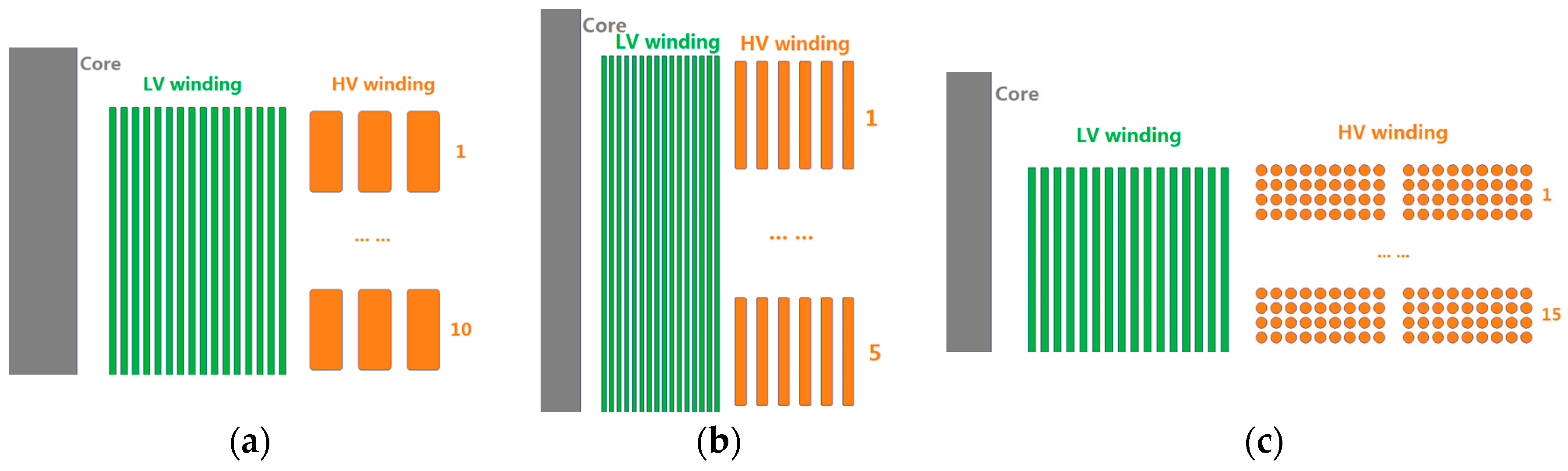
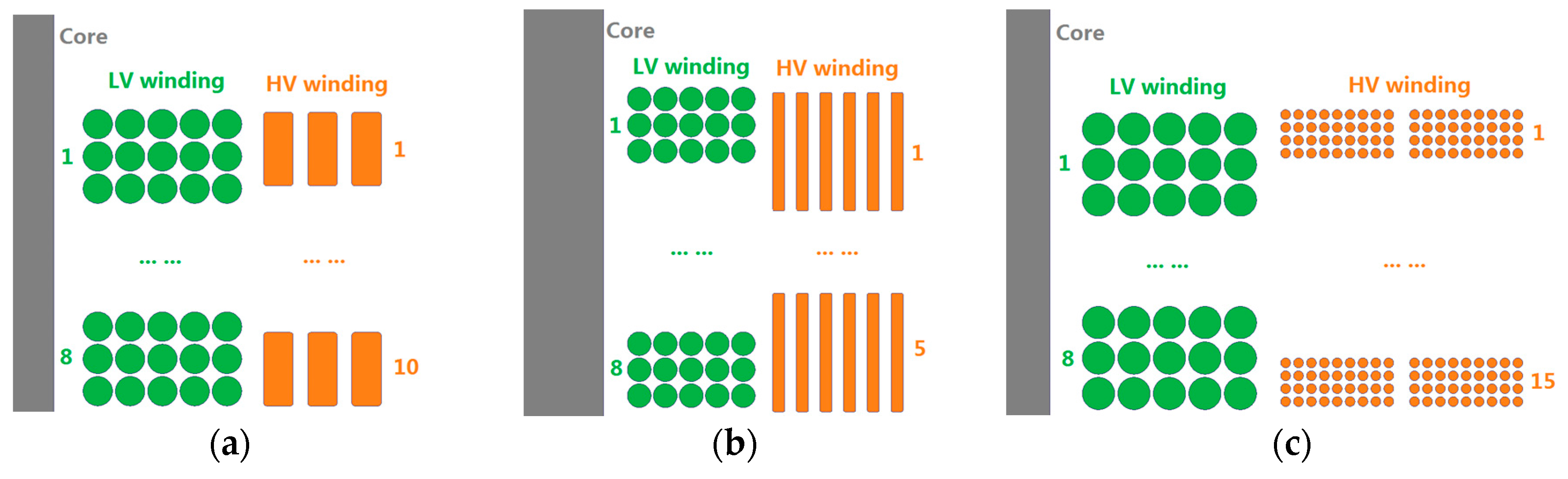
3. Windings with Different Wire Types

3.1. Windings with Different Wire Types

Litz wire, foil conductor, and flat copper wire are three kinds of suitable wire types for MFTs. Six kinds of typical non-interleaved windings N-1, N-2, N-3, N-4, N-5, and N-6 with different wire types are shown in Figure 3a–c and Figure 4a–c respectively. In the context of foil conductors adopted in the secondary winding, the three non-interleaved windings N-1, N-2, and N-3 are shown in Figure 3a–c. In the context litz wires adopted in the secondary winding, the three non-interleaved windings N-4, N-5, and N-6 are shown in Figure 4a–c. The wire types adopted in the six kinds of windings are expounded in Table 2.

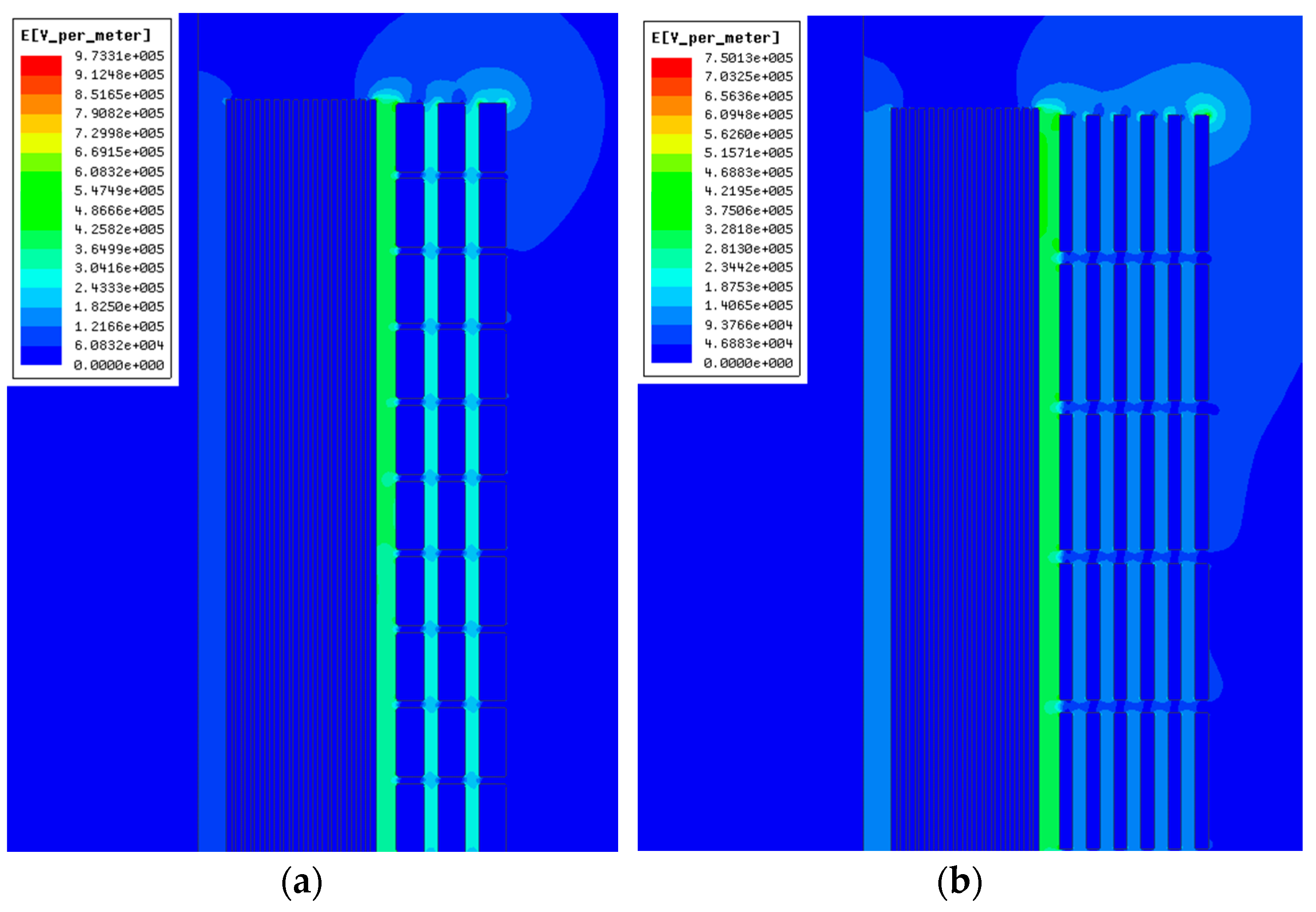
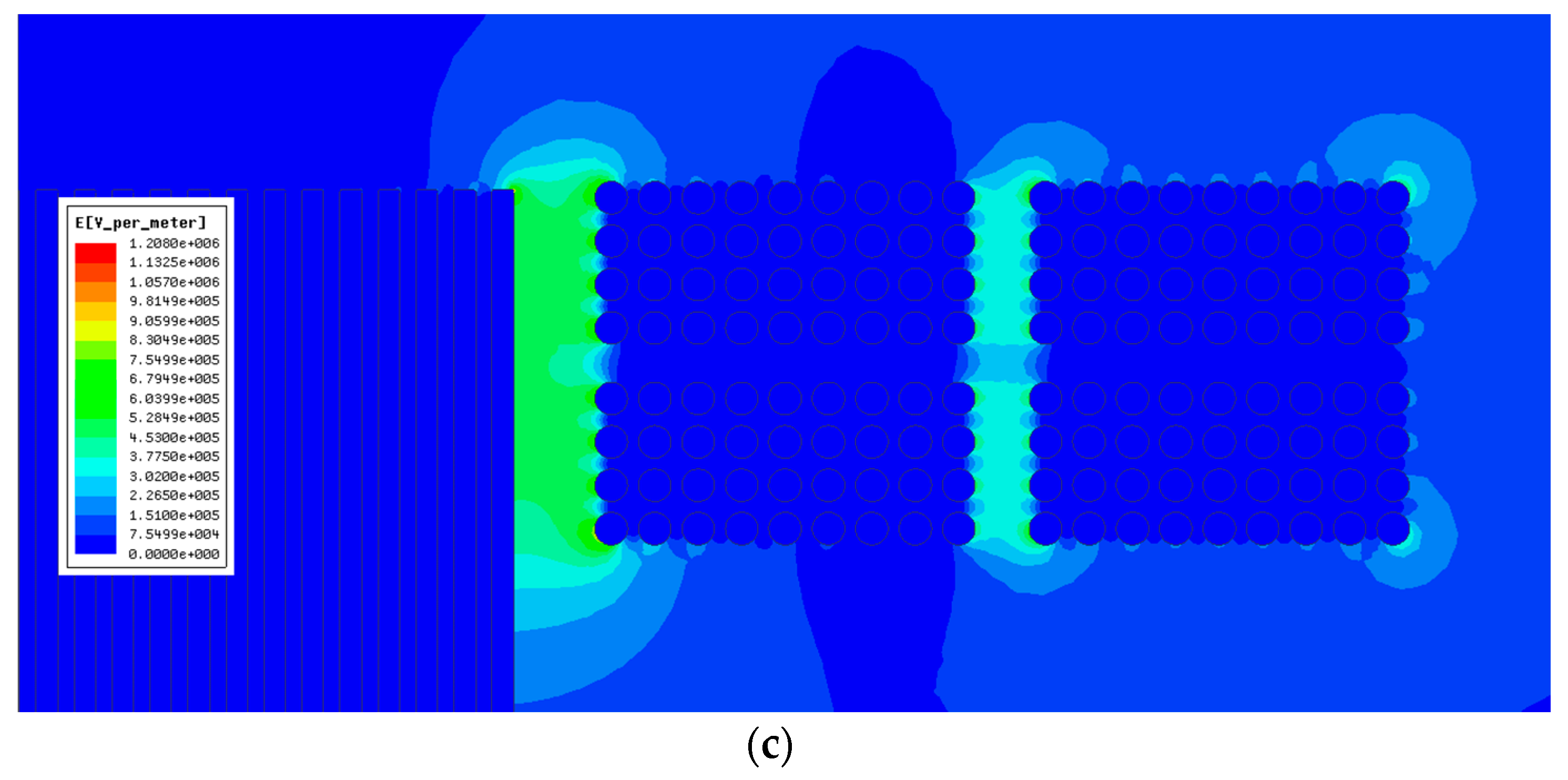
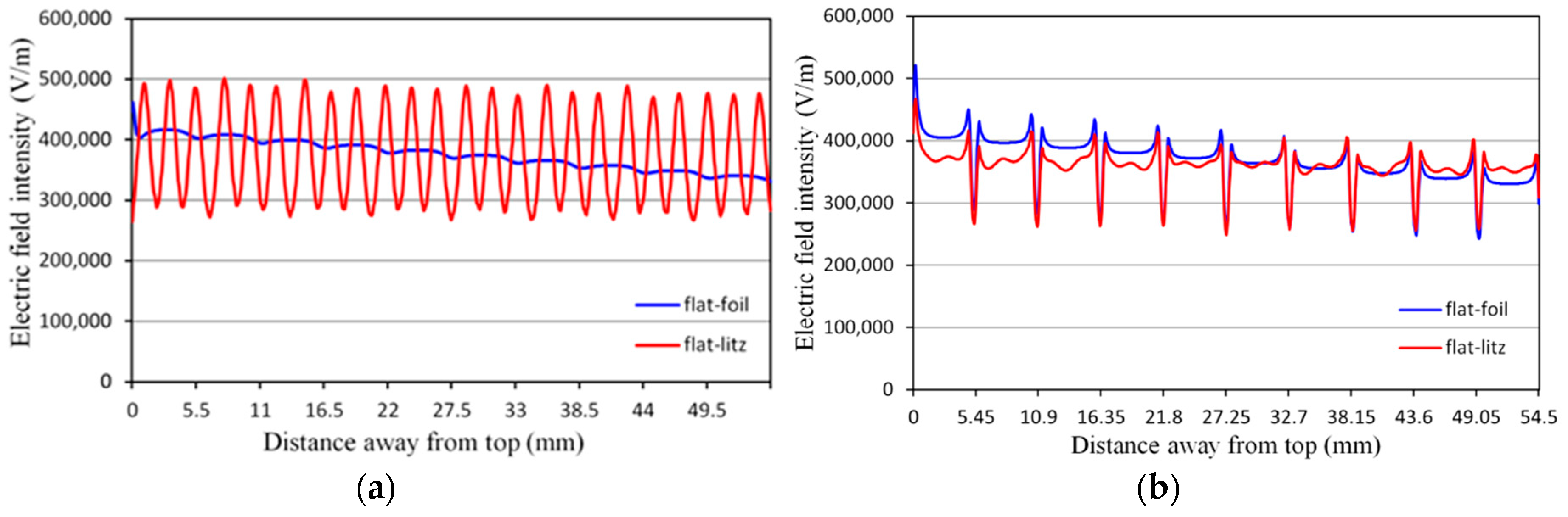
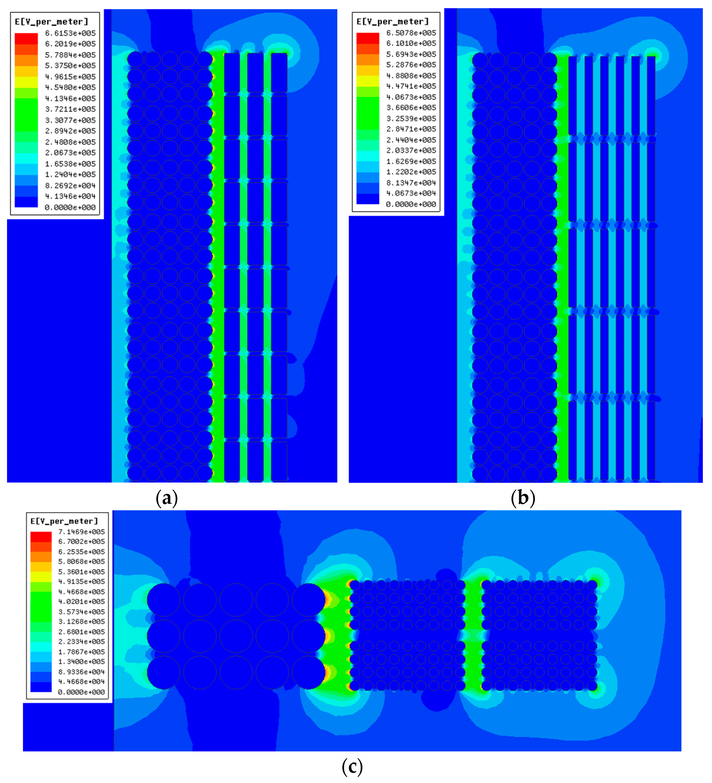
3.2. Electric Field Distribution of Different Windings

2-D finite element models of the six winding structures are established using ANSYS software. The insulation distances between winding layers are 1 mm and 0.3 mm for HV and LV winding layers respectively, and the insulation distance between HV and LV windings is 1.5 mm. A maximum excitation voltage of 1500 V and 384 V are given to HV and LV windings respectively. The excitation voltage decreases from one turn to the next turn, from up to down and from outer to inner. Figure 5a–c and Figure 6a–c show the electric field distributions of the six windings.
As can be seen in Figure 5a–c and Figure 6a–c, for foil conductor winding and flat copper wire winding, the peak value of electric field intensity occurs on the corner of the conductors, while for litz wire winding, the peak value of electric field intensity occurs on the middle edge of the conductors. The maximum electric field intensities Emax of the six winding structures are compared in Table 3. The three windings with the maximum Emax are the windings using foil conductors in secondary winding, including N-1, N-2, and N-3, while the three windings with the minimum Emax are the windings using litz wires in secondary winding, including N-4, N-5, and N-6. According to the results of the maximum electric field intensities of the six windings, in this case study, compared with the foil conductor, smaller maximum electric field intensity can be achieved using litz wire in secondary winding. It is therefore advisable to choose litz wire in secondary winding to achieve a lower Emax.
Furthermore, the electric field intensities on predefined paths are studied. As it can be seen in Figure 5 and Figure 6, the maximum electric field intensities arise in the region between HV and LV windings. Therefore, two paths between HV and LV windings are predefined. Path 1 is a straight line near the LV winding that begins from the top of the LV winding and ends up to the bottom of the LV winding, which is 0.1 mm away from the LV winding, as shown in Figure 2b. Path 2 is a straight line near the HV winding that begins from the top of the HV winding and ends up to the bottom of the HV winding, which is 0.1 mm away from the HV winding, as shown in Figure 2b.
For non-interleaved windings N-1 (flat-foil), N-4 (flat-litz), the electric field intensities on path 1 are shown in Figure 7a. The local maximum electric field intensity on path 1 for winding N-4 is generally higher than that of winding N-1. For non-interleaved windings N-1 (flat-foil), N-4 (flat-litz), the electric field intensities on path 2 are shown in Figure 7b. The local maximum electric field intensity on path 2 for winding N-1 is generally higher than that of winding N-4 in most region. The main difference between windings N-1 and N-4 is that, the wire type of the LV winding is foil conductor for winding N-1, while litz wire for winding N-4. Therefore, in this case study, the foil conductor adopted in the LV winding can relieve the local maximum electric field intensity in the regions near the LV windings, while the litz wire adopted in the LV winding can relieve the local maximum electric field intensity in the regions near the HV winding.

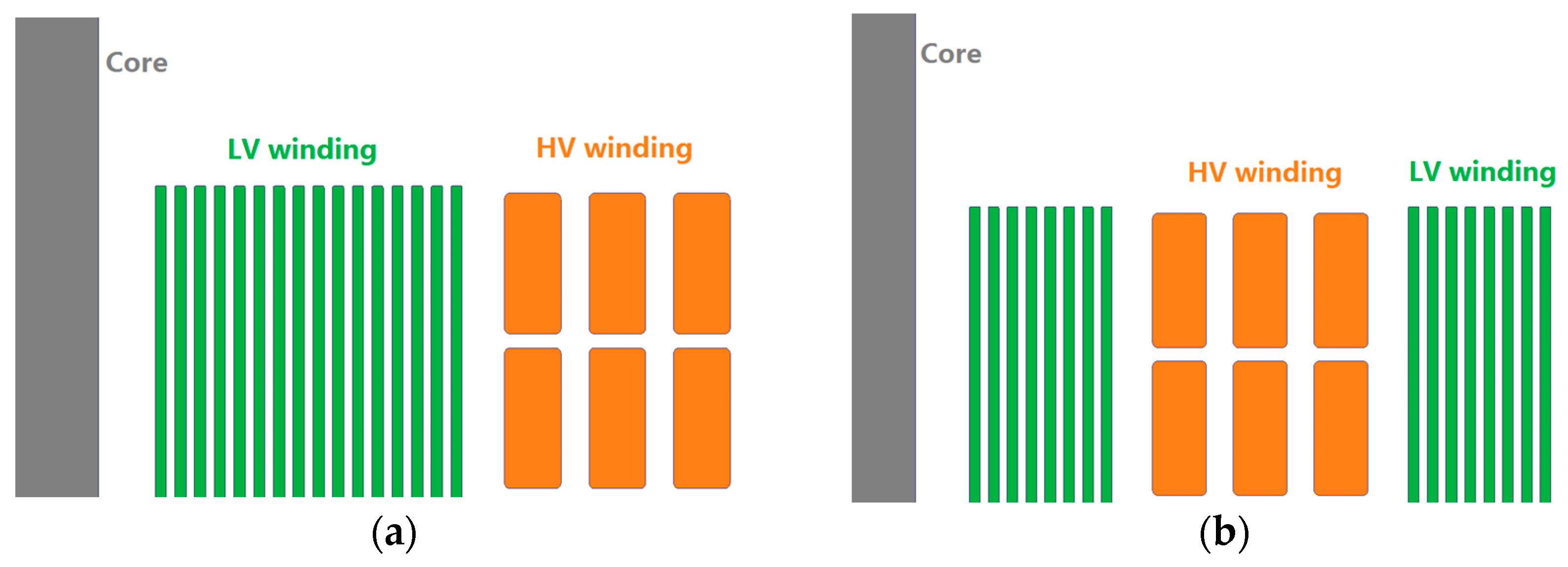
4. Interleaved and Non-Interleaved Windings

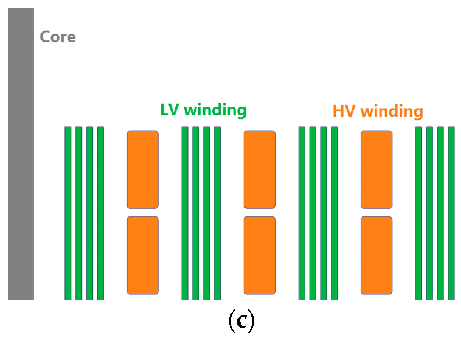
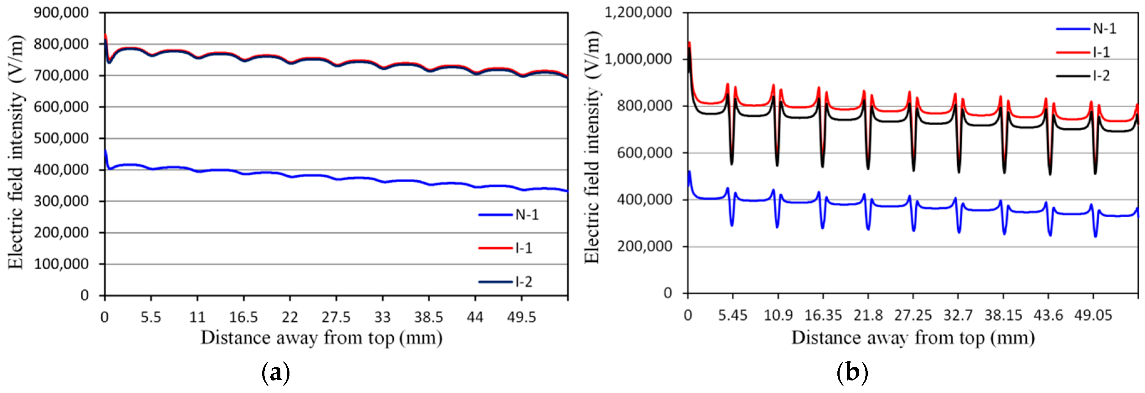
4.1. Interleaved and Non-Interleaved Windings

Figure 8a shows the structure of a typical non-interleaved winding N-1. The foil conductors are adopted in LV winding, and the flat copper wires are used in HV winding. Figure 8b,c illuminates the structures of two kinds of interleaved windings, I-1 and I-2 respectively. It can be seen that the wire types of the three windings are the same.

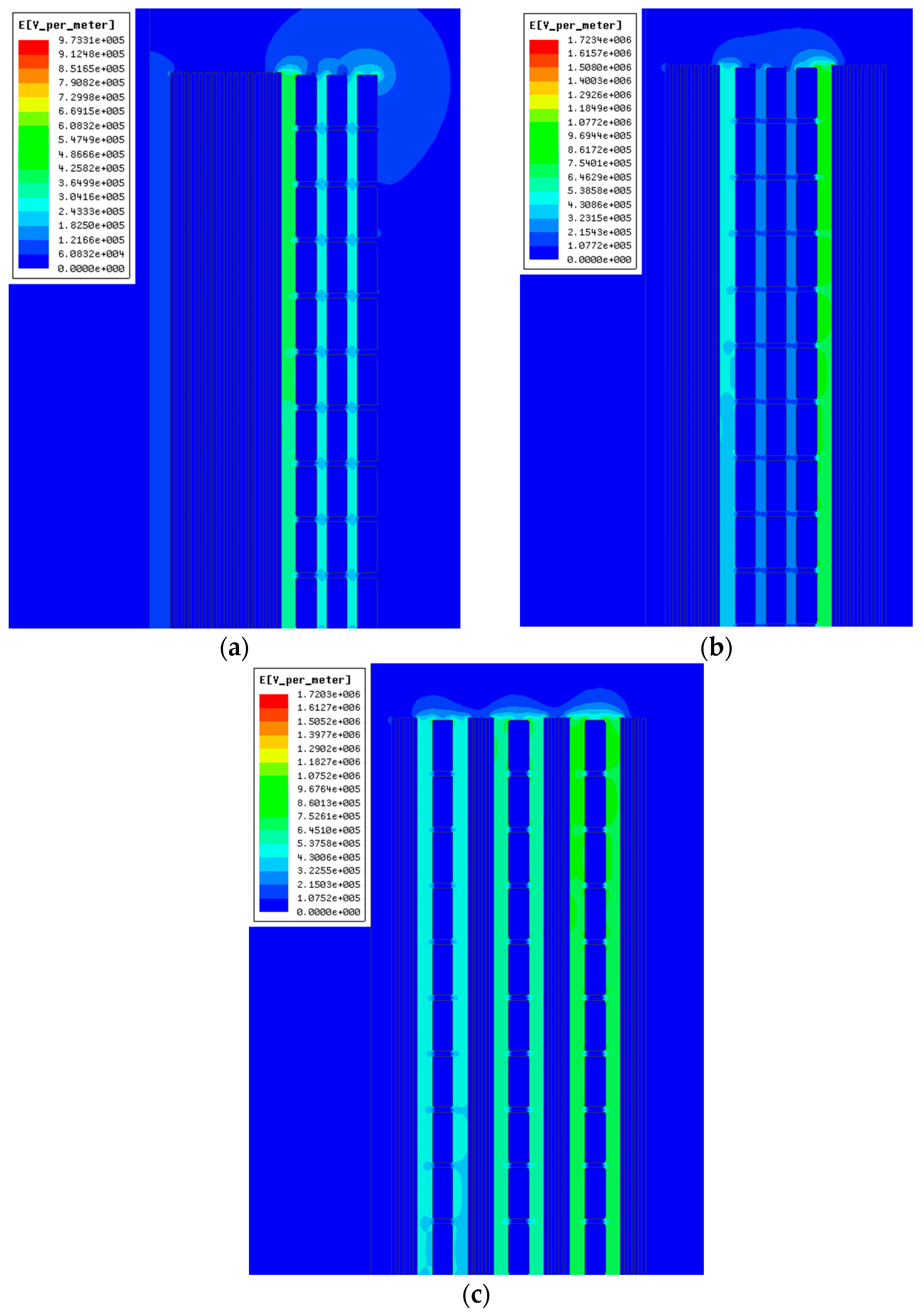
4.2. Electric Field Distribution of Different Windings

2-D finite element models of the three windings are established in ANSYS software. The insulation distances between winding layers is 1 mm and 0.3 mm for HV and LV winding layers respectively, and the insulation distance between HV and LV windings is 1.5 mm. A maximum excitation voltage of 1500 V and 384 V are given to HV and LV windings respectively. The excitation voltage decreases from one turn to the next turn, from up to down, and from outer to inner. Figure 9a–c shows the electric field distributions of the three windings respectively. The maximum electric field intensities Emax of the three windings are compared in Table 4. The interleaved winding I-1 achieves the maximum Emax, and the non-interleaved winding N-1 achieves the minimum Emax among the three windings.
The excitation voltage decreases from one turn to the next turn, from up to down, and from outer to inner. Comparing non-interleaved winding N-1 with interleaved winding I-2, the voltage of the third column is much lower than that of the first column (from outer to inner) for HV winding. Therefore, the voltage difference between the HV and LV windings for winding N-1 is much smaller than winding I-2, and the Emax of winding N-1 is smaller than that of winding I-2. Comparing interleaved winding I-2 with interleaved winding I-1, the voltage of the fifth foil conductor is higher than that of eighth foil conductor (from outer to inner) for LV winding. Therefore, the voltage difference between the HV and LV windings for winding I-2 is smaller than winding I-1, and the Emax of winding I-2 is smaller than that of winding I-1. According to the results of the maximum electric field intensities of the three windings, in this case study, compared with non-interleaved winding, interleaved windings achieve higher maximum electric field intensity. Thus, interleaving can result in the increase of the maximum electric field intensity when insulation distance is constant.
Furthermore, the electric field intensities on path 1 and path 2 for the non-interleaved winding N-1, interleaved windings I-1 and I-2 are investigated. The path 1 and path 2 are placed in the region where the electric field intensity reaches the maximum. For non-interleaved winding N-1, path 1 and path 2 are placed as shown in Figure 2b. For interleaved windings I-1, path 1 and path 2 are placed between the eighth foil conductor of the LV winding and the first column of the HV winding (from outer to inner). For interleaved windings I-2, path 1 and path 2 are placed between the first column of the HV winding and the fifth foil conductor of the LV winding (from outer to inner).
The electric field intensities on path 1 and 2 for the three windings are shown in Figure 10a,b. The electric field intensities on path 1 and 2 of interleaved winding I-1 and I-2 are much higher than those of the non-interleaved winding N-1. According to the simulation results of the three windings, in this case study, interleaving influences the electric field intensity.

5. Conclusions

First, the electric field distributions for six kinds of non-interleaved windings with different wire types are studied using 2-D FEM, and the results show that, compared with foil conductor, smaller maximum electric field intensity can be achieved using litz wire in secondary winding, and it is advisable to choose litz wire in secondary winding to achieve a lower maximum electric field intensity. Second, the electric field distributions for three different winding structures (one non-interleaved winding and two interleaved windings) are also investigated using 2-D FEM, and the results show that interleaving can increase the maximum electric field intensity when insulation distance is constant. Therefore, a change of insulation distance is advisable if interleaved winding is adopted. The proposed method of studying the electric field distribution and analysis results are expected to make a contribution to the improvement of electric field distribution in transformers. Though they are applied to MFT in this paper, the method is general and it is also applicable for power transformers.

Acknowledgments

This work was supported in part by the National Natural Science Foundation of China under Grant no. 51277083, and the National Basic Research Program of China (2015CB251301).

Author Contributions

Chengxiong Mao and Dan Wang proposed the idea and supervised the research; Pei Huang performed the simulations and wrote the paper; all authors contributed to the review of the paper.

Conflicts of Interest

The authors declare no conflict of interest.

References

  1. Huang, H.; Mao, C.; Lu, J.; Wang, D. Electronic power transformer control strategy in wind energy conversion systems for low voltage ride-through capability enhancement of directly driven wind turbines with permanent magnet synchronous generators (D-PMSGs). Energies 2014, 7, 7330–7347. [Google Scholar] [CrossRef]
  2. Tian, J.; Mao, C.; Wang, D.; Lu, J.; Liang, X.; Liu, Y. Analysis and control of electronic power transformer with star-configuration under unbalanced conditions. IET Electr. Power Appl. 2015, 9, 358–369. [Google Scholar] [CrossRef]
  3. Wang, L.; Zhang, D.; Wang, Y.; Wu, B.; Athab, H.S. Power and voltage balance control of a novel three-phase solid-state transformer using multilevel cascaded H-bridge inverters for microgrid applications. IEEE Trans. Power Electron. 2016, 31, 3289–3301. [Google Scholar] [CrossRef]
  4. Wang, X.; Liu, J.; Ouyang, S.; Xu, T.; Meng, F.; Song, S. Control and experiment of an H-bridge-based three-phase three-stage modular power electronic transformer. IEEE Trans. Power Electron. 2016, 31, 2002–2011. [Google Scholar] [CrossRef]
  5. Zhao, C.; Dujic, D.; Mester, A.; Steinke, J.K.; Weiss, M.; Lewdeni-Schmid, S.; Chaudhuri, T.; Stefanutti, P. Power electronic traction transformer—Medium voltage prototype. IEEE Trans. Ind. Electron. 2014, 61, 3257–3268. [Google Scholar] [CrossRef]
  6. Peng, S.; Biela, J. Design and optimization of medium frequency, medium voltage transformers. In Proceedings of the 2013 15th European Conference on Power Electronics and Applications (EPE), Lille, France; 2013; pp. 1–10. [Google Scholar]
  7. Bahmani, M.A. Design and Optimization Considerations of Medium-Frequency Power Transformers in High-Power dc-dc Applications. Ph.D. Thesis, Department of Energy and Environment, Chalmers University Technology, Gothenburg, Sweden, March 2016. [Google Scholar]
  8. Ortiz, G. High-Power DC-DC Converter Technologies for Smart Grid and Traction Applications. Ph.D. Dissertation, Swiss Federal Institute of Technology, ETH, Zürich, Switzerland, November 2013. [Google Scholar]
  9. Ortiz, G.; Biela, J.; Kolar, J.W. Optimized design of medium frequency transformers with high isolation requirements. In Proceedings of the IECON 2010—36th Annual Conference on IEEE Industrial Electronics Society, Glendale, AZ, USA, 7–10 November 2010; pp. 631–638.
  10. Du, S.B.Y.; Gangyao, W.; Bhattacharya, S. Design considerations of high voltage and high frequency transformer for solid state transformer application. In Proceedings of the IECON 2010—36th Annual Conference on IEEE Industrial Electronics Society, Glendale, AZ, USA, 7–10 November 2010; pp. 421–426.
  11. Guillod, T.; Huber, J.E.; Ortiz, G.; De, A.; Franck, C.M.; Kolar, J.W. Characterization of the voltage and electric field stresses in multi-cell solid-state transformers. In Proceedings of the 2014 IEEE Energy Conversion Congress and Exposition (ECCE), Pittsburgh, PA, USA, 14–18 September 2014; pp. 4726–4734.
  12. Qi, B.; Zhao, X.; Li, C.; Wu, H. Transient electric field characteristics in oil-pressboard composite insulation under voltage polarity reversal. IEEE Trans. Dielectr. Electr. Insul. 2015, 22, 2148–2155. [Google Scholar] [CrossRef]
  13. Faiz, J.; Ebrahimi, B.M.; Noori, T. Three- and two-dimensional finite-element computation of inrush current and short-circuit electromagnetic forces on windings of a three-phase core-type power transformer. IEEE Trans. Magn. 2008, 44, 590–597. [Google Scholar] [CrossRef]
  14. González, E.; Gomez, P.; Espino-Cortés, F.P. Analysis of the electric field distribution on insulating supports of dry-type transformers under high temperature. IET Electr. Power Appl. 2013, 7, 331–337. [Google Scholar] [CrossRef]
  15. Khaligh, A.; Vakilian, M. Power transformers internal insulation design improvements using electric field analysis through finite-element methods. IEEE Trans. Magn. 2008, 44, 273–278. [Google Scholar] [CrossRef]
  16. Smajic, J.; Steinmetz, T.; Cranganu-Cretu, B.; Nogues, A.; Murillo, R.; Tepper, J. Analysis of near and far stray magnetic fields of dry-type transformers: 3-D simulations versus measurements. IEEE Trans. Magn. 2011, 47, 1374–1377. [Google Scholar] [CrossRef]
  17. Yamashita, H.; Cingoski, V.; Nakamae, E.; Namera, A.; Kitamura, H. Design improvements on graded insulation of power transformers using transient electric field analysis and visualization technique. IEEE Trans. Energy Convers. 1999, 14, 1379–1384. [Google Scholar] [CrossRef]
  18. Lesniewska, E. The use of 3-D electric field analysis and the analytical approach for improvement of a combined instrument transformer insulation system. IEEE Trans. Magn. 2002, 38, 1233–1236. [Google Scholar] [CrossRef]
  19. Salihu Mustafa, S.; Misron, N.; Mariun, N.; Othman, M.; Hanamoto, T. Torque distribution characteristics of a novel double-stator permanent magnet generator integrated with a magnetic gear. Energies 2017, 10, 2. [Google Scholar] [CrossRef]
  20. Barrios, E.L.; Urtasun, A.; Ursua, A.; Marroyo, L.; Sanchis, P. High-frequency power transformers with foil windings: Maximum interleaving and optimal design. IEEE Trans. Power Electron. 2015, 30, 5712–5723. [Google Scholar] [CrossRef]
  21. Wang, D.; Mao, C.; Lu, J. Modelling of electronic power transformer and its application to power system. IET Gener. Transm. Distrib. 2007, 1, 887–895. [Google Scholar] [CrossRef]
Figure 1. The topology of dc-dc converter.
Energies 10 00371 g001
Figure 2. Instructions of this MFT: (a) Structure of the modeled MFT; (b) Meshed 2-D model.
Energies 10 00371 g002
Figure 3. Winding arrangements for different windings: (a) N-1; (b) N-2; (c) N-3.
Energies 10 00371 g003
Figure 4. Winding arrangements for different windings: (a) N-4; (b) N-5; (c) N-6.
Energies 10 00371 g004
Figure 5. Electric field distribution for different windings: (a) N-1; (b) N-2; (c) N-3.
Energies 10 00371 g005aEnergies 10 00371 g005b
Figure 6. Electric field distribution for different windings: (a) N-4; (b) N-5; (c) N-6.
Energies 10 00371 g006
Figure 7. Electric field intensities on path 1 and path 2 for winding N-1 (flat-foil) and winding N-4 (flat-litz): (a) Electric field intensities on path 1; (b) Electric field intensities on path 2.
Energies 10 00371 g007
Figure 8. Winding arrangements (partial) for three windings: (a) Non-interleaved winding N-1; (b) Interleaved winding I-1; (c) Interleaved winding I-2.
Energies 10 00371 g008aEnergies 10 00371 g008b
Figure 9. Electric field distribution for three windings: (a) Non-interleaved winding N-1; (b) Interleaved winding I-1; (c) Interleaved winding I-2.
Energies 10 00371 g009
Figure 10. Electric field intensities on path 1 and path 2 for windings N-1, I-1 and I-2: (a) Electric field intensities on path 1; (b) Electric field intensities on path 2.
Energies 10 00371 g010
Table 1. Specifications and parameters of the 35 kW MFT.
ParameterSymbolValue
Number of Phase N1
Operation frequencyf1 kHz
PowerP35 kW
Maximum primary voltage Upmax1.5 kV
Maximum secondary voltageUsmax385 V
Rms primary currentIp26.3 A
Rms secondary currentIs102 A
Primary/secondary turn numbersNp/Ns120/32
Size of the foil conductorWidth/Length0.4 mm/110 mm
Size of the flat copper wireWidth/Length2 mm/5 mm
Max. length of elements for corenull30 mm
Max. length of elements for windingnull0.1 mm
Table 2. Wire types of the six kinds of windings.
Winding TypeHV WindingLV Winding
N-1 (flat-foil)Flat copper wireFoil conductor
N-2 (foil-foil)Foil conductorFoil conductor
N-3 (litz-foil)Litz wireFoil conductor
N-4 (flat-litz)Flat copper wireLitz wire
N-5 (foil-litz)Foil conductorLitz wire
N-6 (litz-litz)Litz wireLitz wire
Table 3. Maximum electric field intensities.
Winding TypeEmax (V/m)Winding TypeEmax (V/m)
N-1 (flat-foil)9.7331 × 10⁵N-4 (flat-litz)6.6153 × 10⁵
N-2 (foil-foil)7.5013 × 10⁵N-5 (foil-litz)6.5078 × 10⁵
N-3 (litz-foil)1.2080 × 10⁶N-6 (litz-litz)7.1469 × 10⁵
Table 4. Maximum electric field intensities.
Winding TypeEmax (V/m)
Non-interleaved N-19.7331 × 10⁵
Interleaved I-11.7234 × 10⁶
Interleaved I-21.7203 × 10⁶

