Article

Engineering Smart Grids: Applying Model-Driven Development from Use Case Design to Deployment

by
Filip Pröstl Andrén
1,*,
Thomas I. Strasser
1 and
Wolfgang Kastner
2
1
Center of Energy-Electric Energy Systems, AIT Austrian Institute of Technology, Vienna 1210, Austria
2
Institute of Computer Aided Automation, Vienna University of Technology, Vienna 1040, Austria
*
Author to whom correspondence should be addressed.
Energies 2017, 10(3), 374; https://doi.org/10.3390/en10030374
Submission received: 20 December 2016 / Revised: 28 February 2017 / Accepted: 9 March 2017 / Published: 16 March 2017
(This article belongs to the Special Issue Innovative Methods for Smart Grids Planning and Management)

Abstract

:
The rollout of smart grid solutions has already started and new methods are deployed to the power systems of today. However, complexity is still increasing as focus is moving from a single system, to a system of systems perspective. The results are increasing engineering efforts and escalating costs. For this reason, new and automated engineering methods are necessary. This paper addresses these needs with a rapid engineering methodology that covers the overall engineering process for smart grid applications—from use case design to deployment. Based on a model-driven development approach, the methodology consists of three main parts: use case modeling, code generation, and deployment. A domain-specific language is introduced supporting the use case design according to the Smart Grid Architecture Model. It is combined with the IEC 61499 distributed control model to improve the function layer design. After a completed use case design, executable code and communication configurations (e.g., IEC 61850) are generated and deployed onto compatible field devices. This paper covers the proposed rapid engineering methodology and a corresponding prototypical implementation which is validated in a laboratory experiment. Compared to other methods the proposed methodology decreases the number of engineering steps and reduces the use case design and implementation complexity.

1. Introduction

The smart grid has arrived, with new mechanisms for measurement, control, and automation being implemented in today’s power systems. There is a continuously growing demand for electricity, which must be satisfied by the electric energy systems worldwide. At the same time, a stable and secure supply must be guaranteed. The power generation is still mainly dominated by burning fossil fuels resulting in increasing CO 2 emissions and global warming [1]. In order to mitigate this process, there is an obvious trend towards a sustainable electric energy system. Fossil fuels are being replaced by renewable sources (solar and wind generators, biomass, and combined heat-and-power systems, etc.) [2]. Also, consumer side solutions like demand side management, direct market participation, and smart metering are currently in development [3]. The large-scale integration of renewable sources and changes on the consumption side are causing challenges—but also providing opportunities—for the whole electric power system. Automation and control systems, using advanced Information and Communication Technology (ICT), are key elements to handle these new challenges [4].
Accompanying these new technology developments, further research and regulatory alterations are needed. A characteristic feature of renewable sources and customer side solutions is that they are mostly available in a decentralized way as Distributed Energy Resources (DER) [5]. This introduces challenges, which cannot be tackled only using pure technical solutions. Changes in regulations and grid codes are also necessary. Consequently, the planning, management, and operation of the future power systems have to be redefined.
The implementation and deployment of these complex systems of systems are associated with increasing engineering complexity resulting also in increased total life-cycle costs. However, with the usage of proper methods, automation architectures, and corresponding tools there is a huge optimization potential for the overall engineering process. One very promising method to increase the efficiency is a detailed use case and requirements engineering. This trend can be observed in a number of recent smart grid projects where use case descriptions of corresponding applications (e.g., voltage control, energy management, demand-response) are in focus [6,7]. Different methodologies and standards exist today for describing such use cases. Two of the most common methods are the Smart Grid Architecture Model (SGAM) [8] and the IEC 62559 approach [9] (formerly known as the IntelliGrid method). The main aim of use case descriptions and derived requirements is to provide a clear and concise documentation of the application, which can be used as a common basis for further developments [10].
Using a methodology, like SGAM or IEC 62559, a high amount of information in the modeled use cases is already available. However, since this information is still in a non-formal representation, it is difficult to use it directly in a computerized and automated approach. Thus, a significant amount of work has to be done a repeated number of times—first during specification and later during the implementation phase. However, if the information gathered in the description phase can also be used directly in an automated method, the development effort can be substantially decreased. Moreover, an automated approach also has the potential to decrease implementation errors and at the same time increase the application and software quality [11,12].
The main aim of this paper is showing the possibility to create an automated engineering framework that covers the whole development process of smart grid automation applications—from use case specification(s) to corresponding platform-specific implementation(s). To show this, a Model-Driven Engineering (MDE) approach is proposed. A core part of this approach is a Domain-Specific Language (DSL) based on SGAM. This DSL provides a formal description of the SGAM methodology, with the goal to automate and shorten the design process of use cases. In addition, this DSL is further used together with existing programming techniques for code generation and deployment of power utility applications. The DSL, together with the code generation feature, provide a rapid engineering environment for power utility automation use cases. Another important aspect is that it can also be used for laboratory validation of smart grid systems. This issue has received a much higher focus in recent and ongoing European and international projects (e.g., FP7 ELECTRA IRP, H2020 ERIGrid, H2020 SmartNet, FP7 DISCERN, IEA ISGAN/SIRFN) [13].
The remaining part of the paper is organized as follows: Section 2 presents the related work and provides a description of the MDE paradigm. In Section 3, the rapid engineering methodology is proposed and the DSL is introduced. Section 4 shows how the rapid engineering methodology can be used for code generation. Thereafter, the modeling and implementation of a use case example is shown in Section 5. The proof-of-concept validation of the proposed methodology is presented in Section 6. Finally, Section 8 presents the conclusions and provides an outlook about the planned future work.

2. Related Work

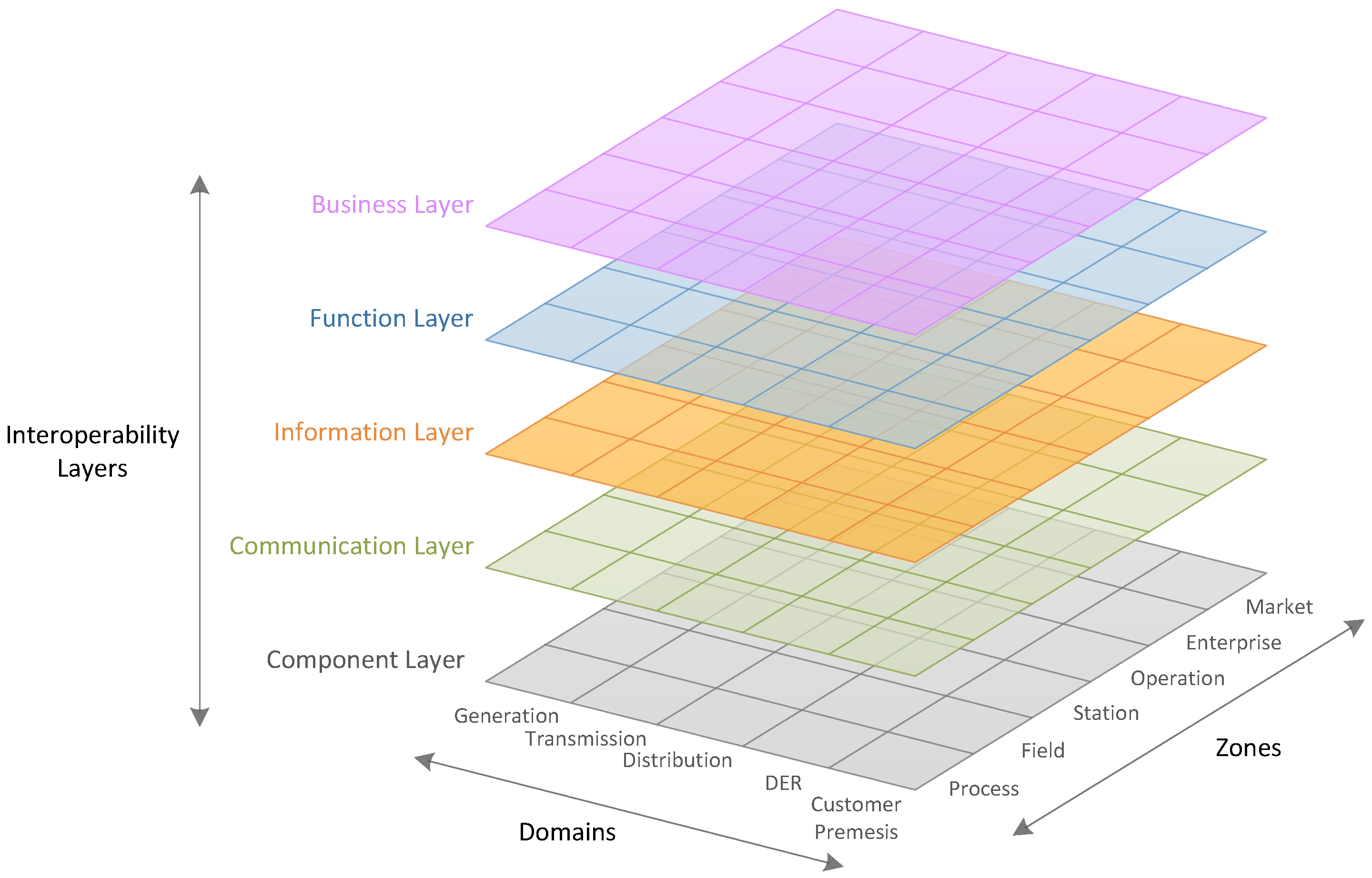
2.1. Use Case Descriptions According to the Smart Grid Architecture Model

SGAM was created as a result of the “European Commission M/490 Standardization Mandate to European Standardization Organizations (ESO)” [14]. It provides a structured approach for modeling smart grid use cases. The basis for SGAM is a three-dimensional framework consisting of domains, zones, and layers. In the domains, the traditional layout of the electrical energy infrastructure can be found: generation, transmission, distribution, DER, and customer premises. The zones depict a typical hierarchical power system management: market, enterprise, operation, station, field, and process. These two axes form the component layer. On top of the component layer, four interoperability layers are placed: the communication, information, function, and business layers [8]. An overview of this three-dimensional model is provided in Figure 1.
Accompanying the framework in Figure 1, a use case design methodology is also provided. It is based on the IEC 62559 use case template, which is used as a basis for describing use cases. These are subsequently mapped into the different layers of SGAM. In order to do this in a structured way, the following design steps are defined [15,16]:
  • Use Case Analysis: The first step is an analysis of the use case. It is suggested to use the IEC 62559 template to create an initial use case description [16].
  • Business Layer Design: The business processes, services, and organizations, which are linked to the use case, are mapped to the business layer. These business entities are placed in the appropriate domain and zone.
  • Function Layer Design: In the function layer, functions and their interrelations should be represented. The functions are derived from the initial use case description. A use case can be hierarchically divided into sub use cases and functions.
  • Component Layer Design: After the business layer and the function layer have been modeled, they have to be matched with a certain system. Thus, the next step is to model the component layer. Based on the actors involved in the use case, and any existing system components, the needed components for the use case can be derived and assigned to a domain and zone. Subsequently, the derived functions from the function layer can be assigned to a corresponding hardware.
  • Information Layer Design: In the information layer, the information exchanged between functions, services, and components is represented. Information objects can be identified by analyzing the data exchanged between actors involved in the use case (e.g., using sequence and activity diagrams). Another important aspect of this layer is to represent which data models are used for the information exchange.
  • Communication Layer Design: Taking the exchanged information and data models identified in the information layer into account, suitable communication protocols and ICT techniques have to be identified. These should be represented in the communication layer.
From an engineering point of view, most effort is put into the first step (i.e., the use case analysis). In order to support the user with the methodology described above, Dänekas et al. developed the so-called “SGAM Toolbox”, a Unified Modeling Language (UML)-based DSL available as an extension to the Enterprise Architect software [17]. One advantage of the SGAM Toolbox is that common UML modeling tools like sequence and activity diagrams are available, since these are standard parts of Enterprise Architect. Consequently with the SGAM Toolbox, only one tool is needed covering all steps in the SGAM methodology. The main idea of the SGAM Toolbox is to provide support for traditional use case descriptions. Furthermore, it is also possible to use the code generation capabilities provided by Enterprise Architect.

2.2. Power Utility Automation

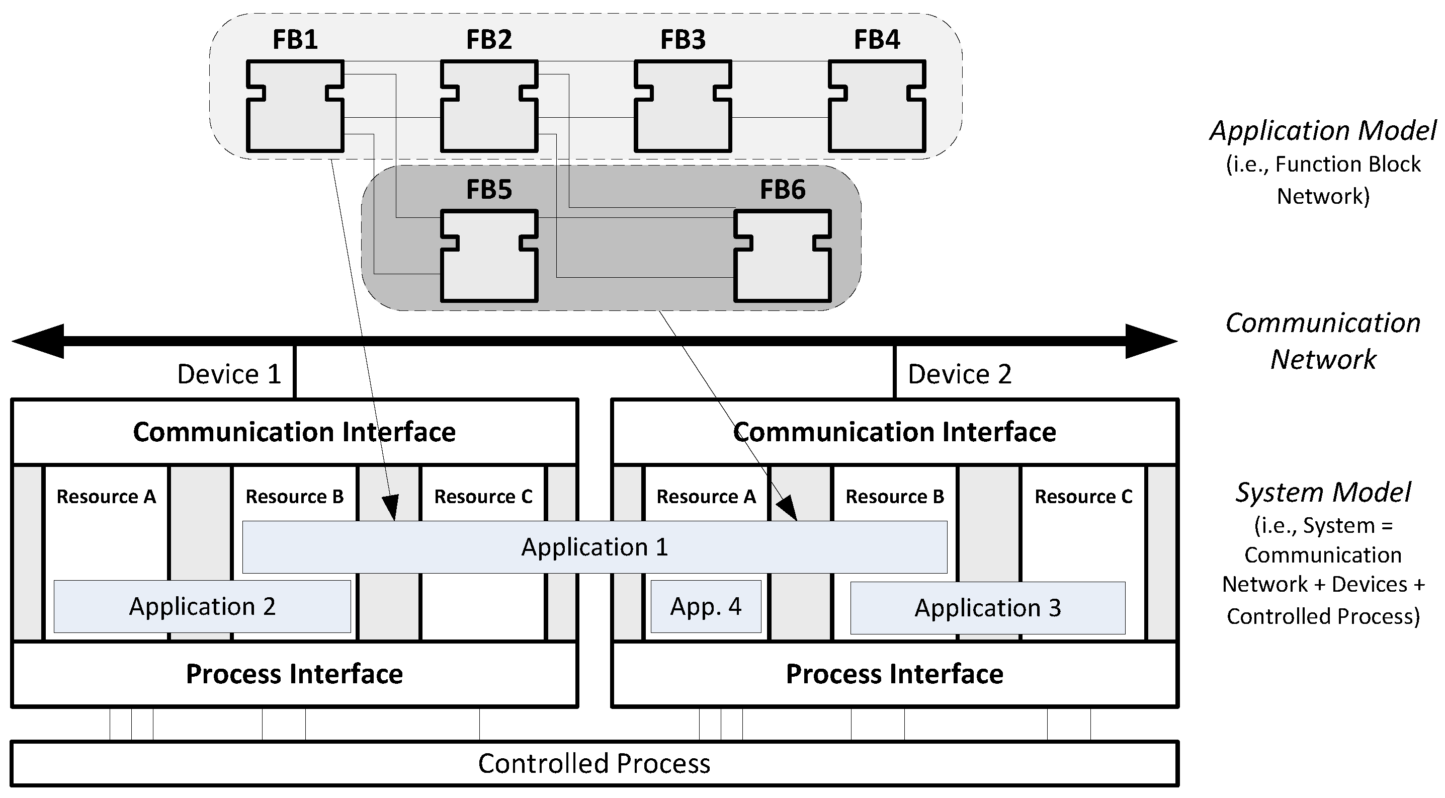
2.2.1. Distributed Control Reference Model—IEC 61499

The IEC 61499 standard is an automation approach developed to model distributed industrial-process measurement and control systems. IEC 61499 has a high focus on multi-vendor support and interoperability. To achieve this, it defines a reference architecture and corresponding models for distributed automation and control systems used in industrial environments. One of the main aims of IEC 61499 is to support distributed automation applications, and therefore it allows the user to model the overall control solution—i.e., the control application and the hardware setup [18].
The core modeling elements of this automation approach are so called Function Blocks (FB) that encapsulate modular control software. Multiple FBs connected together into an FB network make up an IEC 61499 Application. The IEC 61499 FB model is based on its predecessor IEC 61131-3 [19] but uses events for defining the execution flow. Once an “Application” has been defined it can be deployed to field devices, called “Devices” in the standard [18]. In Figure 2 an overview of the main IEC 61499 elements is provided.

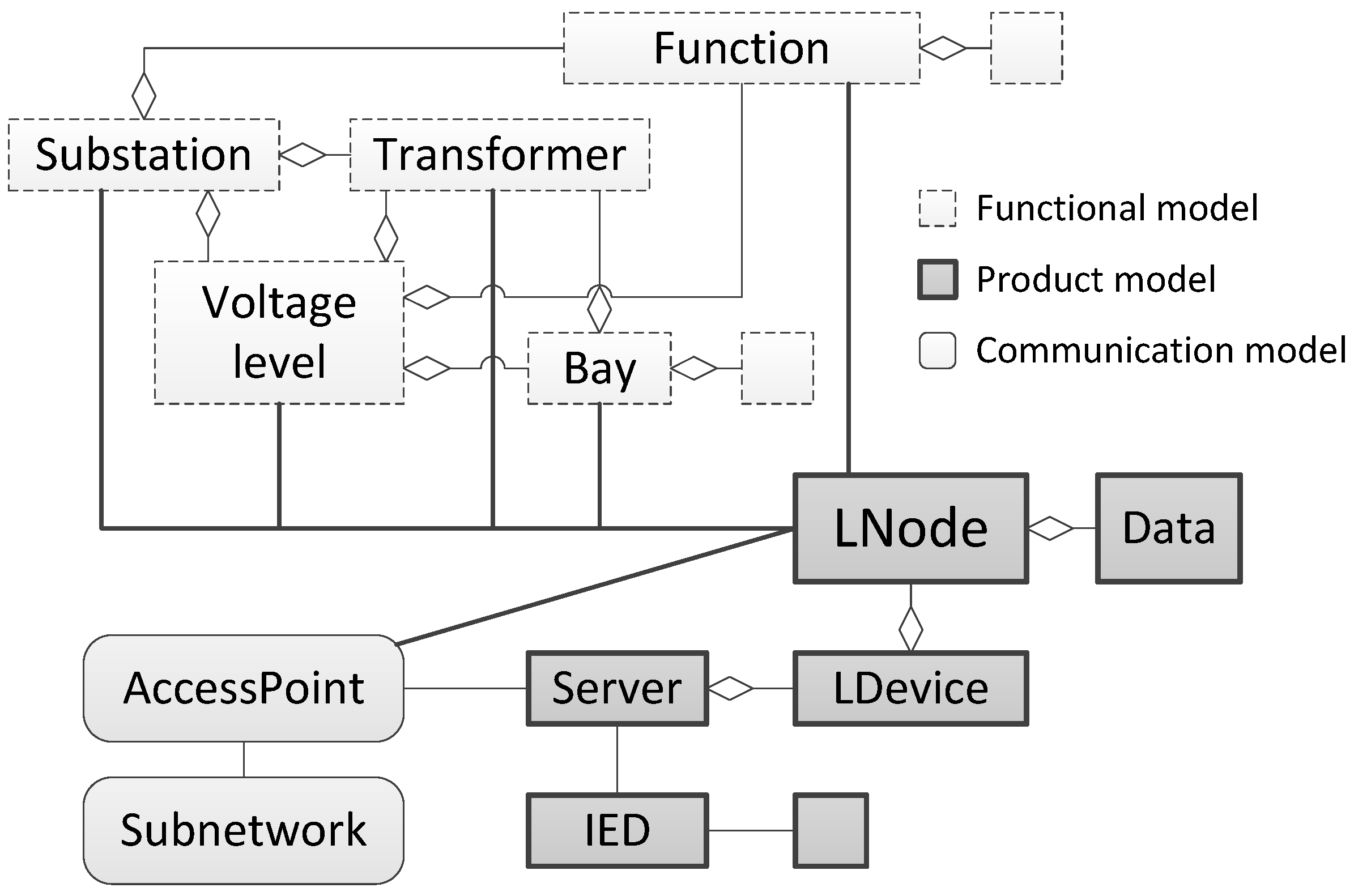
2.2.2. Interoperability in Power Systems—IEC 61850

The IEC 61850 approach focuses on an increased interoperability between so-called Intelligent Electronic Devices (IED) [21]. Its original purpose was to provide a new approach for the automation of substations, but has since its first publication been extended to cover other smart grid areas (e.g., Phasor Measurement Units (PMU), DER components). The focus is on multi-vendor support in the power systems domain. Basically, IEC 61850 includes two main parts: power system modeling and communication between components of the electricity system.
Logical Nodes (LN) are the main parts of IEC 61850 and are used to model power system components (e.g., switches, transformers, inverters) as well as power system functions (e.g., measurement, protection, voltage control). LNs can be grouped together into Logical Devices (LD), contained in IEDs, providing a kind of structural modeling. For configuration of IEDs, the XML-based System Configuration Language (SCL) is provided. It described functions of IEDs using the LD and LN definitions as well as the data exchange between devices in a formalized way [21]. Figure 3 shows the main modeling objects provided by IEC 61850.
Furthermore, IEC 61850 also defines communication services for the data transfer between devices. This includes client/server-based but also publish/subscriber-based communication principles as well as real-time communication (i.e., Sampled Value, GSE, and GOOSE).
Intelligent devices are one of the major preconditions for the realization of smart grids [22]. In this context, IEC 61850 plays a major role for the standardized information and data exchange. However, it only defines interfaces for control services and protection functions. The implementation of such functions and services is not covered by IEC 61850 but must be implemented using other solutions (e.g., IEC 61131-3, IEC 61499).

2.3. Model-Driven Architectures & Domain-Specific Concepts

As an MDE initiative, the Model-Driven Architecture (MDA) approach was developed by the Object Management Group (OMG) and has gained interest in computer science as one possibility to improve the software development process [11,12]. It consists of three main parts. Platform-independent application software models are implemented using a Platform-Independent Model (PIM). In order to execute this model, it must first be transformed into a Platform-Specific Model (PSM). The PSM describes the model in terms of a specific execution platform. The transformation of the PIM into a PSM is the third main part of MDA. For this purpose, Query View Transformation (QVT) was specified as a transformation language by OMG. It allows the definition of transformation rules for the mapping of different domain models [23].
Closely related to the MDA approach is the concept of DSLs [24,25]. A DSL is a language which is especially defined to describe or solve problems of a certain domain. One such problem could, for example, be to describe a PIM for a certain domain. Basically, the idea is to allow domain experts to develop applications using a language with domain-specific notation instead of using general-purpose definitions. One advantage of a domain-specific notation is that it increases the understanding of what a code implies. Consequently, errors are easier to detect, which also helps to improve the application and software quality [24]. In principle, either a graphical or a textual notation can be used. In both cases, the use of a secondary notation, the placement of graphical blocks or indention of text, is important to support the understanding. Whereas a graphical notation usually offers a lot of design freedom, textual notations are more constrained and linear [26].

2.4. Model-Driven Engineering for Smart Grid Application Development

The use of formalized approaches is increasing, also for smart grid applications. Especially with regard to communications, an effort has been made to increase the interoperability. This has resulted in a number of formalized information models [27,28] and ontologies [29]. However, these solutions mainly focus on interoperability during operation and do not directly cover the engineering process for smart grid applications.
Until now, the use of MDE in smart grids is limited [30]. Although the previously mentioned SGAM Toolbox follows the MDA approach, its main purpose is not focused on code generation [17]. However, thanks to the integrated code generation capabilities of Enterprise Architect, this option is also available for users of the SGAM Toolbox. The drawbacks with this code is that it is not optimized for power utility applications and communication configurations are not covered.
Another MDE example where code generation is more in focus is presented by Paulo et al. for designing substation automation systems based on UML [31]. In this solution, substation automation systems are designed using UML where IEC 61131-3 control functions can be included into the modeling concept. Another example is shown in the work by Yang et al., where a method to automatically generate IEC 61499 applications based on IEC 61850 configurations is presented [32]. Although these two examples show how MDE can be used for code generation they do not follow the SGAM approach, as compared to Dänekas et al. [17].
An example where specific low-level communication code is generated is presented by Blair et al. [33]. In their approach C code is automatically generated based on IEC 61850 SCL files. With this code publish/subscriber communication, using GOOSE, is created. The work by Blair et al. presents a rapid engineering of communication services but does not focus on the automatic generation of the control functionality. Also, this work does not follow the SGAM approach.
Summarizing, up to now, there is no integrated approach available that covers the complete engineering process, from use cases specification to an executable implementation, using an MDE approach that can handle the multi-domain aspect of smart grids. Therefore, the goal of this work is to show that such a holistic approach is feasible and to fill the gaps that are still existing for rapid engineering of power utility applications. This work is mainly based on [34,35]. In [34], the outline of an MDE approach for smart grid application engineering was presented. A part of the proposed solution is presented in [35], where a DSL for SGAM compliant use case design is introduced. The current work completes the implementation of the MDE approach from [34]. A formal model of the DSL from [35] is presented, together with a formal approach for the generation of executable code and communication configurations. The result is a rapid engineering methodology for smart grid automation applications, which is described in detail in the following section.

3. Creating a Rapid Engineering Methodology for Smart Grid Automation

The main purpose of this methodology is to provide a rapid engineering environment—from use case design to realization—for the development of ICT, control, and automation functions used in smart grid and power utility automation applications. It is important that the methodology considers the current state-of-the-art for use case descriptions, and for this purpose SGAM is used as reference. Consequently, use case design on multiple levels of detail must be supported, but always with the possibility for rapid implementation as a main target.
The methodology presented in this work focuses on the specification and implementation process of smart grid use cases. Although possible, it is not intended to use the methodology for more than one use case at the time. Furthermore, the methodology is, at the moment, not intended for requirements capture or solely for the documentation of existing systems (e.g., a whole utility system with existing power, ICT, and automation infrastructure).

3.1. Actors and Requirements

Before the engineering method can be conceptualized, requirements must be identified. Some of them may be directly derived from the main goal of this work. Other requirements are more related to the actual implementation process and the user. Therefore, actors and stakeholders must be identified before requirements can be derived.

3.1.1. Actors and Stakeholders

Based on related work and the experience from relevant research projects [13,36,37] a number of actors are identified. They are stakeholders, with an economical goal, and users of the engineering methodology. Table 1 shows the identified actors without any specific order.
The goal is that the engineering methodology should support all these actors when designing, implementing, and deploying smart grid automation applications to the field. In the next section, the most important requirements, which are common for all actors, are introduced.

3.1.2. Requirements

Focusing on the actors from Table 1, requirements need to be identified In Table 2 engineering requirements are listed that are common for the above mentioned actors. Of course each actor may have his/her own specific requirements, especially related to a platform-specific implementation.

3.2. General Concept

There are of course different paths to achieve the same goal. However, some reference points are already defined. The SGAM methodology represents a state-of-the-art for use case specifications today. This is also an appropriate starting point for the proposed rapid engineering methodology. At the end of the path executable and deployable code should be available for power utility automation devices. Due to the wide range of engineering tasks, a number of challenges can be identified:
  • Rapidness and Effort: Smart grid solutions are becoming more and more complex resulting in increased engineering efforts and costs. Therefore, it is important to improve the rapidness of traditional engineering methods.
  • Correctness: Due to the multidisciplinary character of smart grid applications this also requires the engineer to have an expert knowledge in each discipline [13]. This is often not the case, which increases the risk of human errors.
  • Handling Legacy Systems: Grid operators expect a long service life of all components in their systems. Since not all devices are changed at the same time it must be possible to handle already existing legacy systems and corresponding units.
  • Geographical Dispersion: The distribution of components over large geographical areas requires new ICT approaches and wide-area communication—also for the engineering.
  • Interoperability: Interoperability is a critical issue in smart grid applications. This must be assured on all levels, from specifications over implementation, to deployment and finally during operation. Also components from different manufacturers must be handled, which requires a manufacturer independent method.
  • Real-Time Constraints: Some applications may enforce real-time constraints on hardware and software. This may demand for special consideration during the whole engineering process.
These challenges are used as a motivation for the methodology developed in this work. It also introduces software engineering concepts in order to automate the process from use case design to implementation. In Figure 4, a conceptual overview of this method is outlined. The concept consists of three main phases: (i) a modeling and design phase; (ii) a function and code generation phase; and (iii) finally a deployment phase.
In the modeling and design phase, a use case design is made. For this purpose, the layered approach of SGAM is used as a reference. In this phase it is also possible to specify functions. In the second phase, function and code generation, the first step is a function generation part. In this step, functions that have been initially specified in the use case design phase are further developed. This can be an automatic process (e.g., based on standards and other documented functions [21]) or a manual process. In this paper, the focus will be on the manual process.
Based on the use case and the developed functions, two types of code are generated: executable code and configurations for communication. The executable code is platform-specific code, which can be executed on a certain computing platform. This could also be a simulation platform and in this case the corresponding simulation model is generated (not covered by this paper). The communication configurations (also called communication code, see Figure 4) are used to configure the communication setup needed for the use case. This includes configuration of the information exchanged between actors, but can also be a low-level configuration of the network. From a cost and time perspective, this is an important phase, since it saves the engineer the manual work of translating the designed use case into an actual realization.
The last phase is the deployment of the generated code to the corresponding field devices. This includes transferring the generated and compiled code to the devices and starting the application. Preferably, this should also be possible to handle in an automated way.
Although the rapid engineering methodology in Figure 4 focuses on applications for power utility automation, it has many similarities with MDE methods for software development. One of these approaches is the MDA approach, described in Section 2.3. As depicted in Figure 4 the modeling and design phase can also be considered as a PIM. Through the function and code generation in the second phase, the PSM is created. Finally, code is deployed to field devices in the deployment phase. Analogous to the MDA approach, the PIM is created using a DSL. In this work, the DSL is called the “Power System Automation Language” (PSAL) and is described in Section 3.3. Transformation rules are used to transform the PIM into a PSM. How this step is carried out and how the PSM can be composed is explained in the following Section 4.

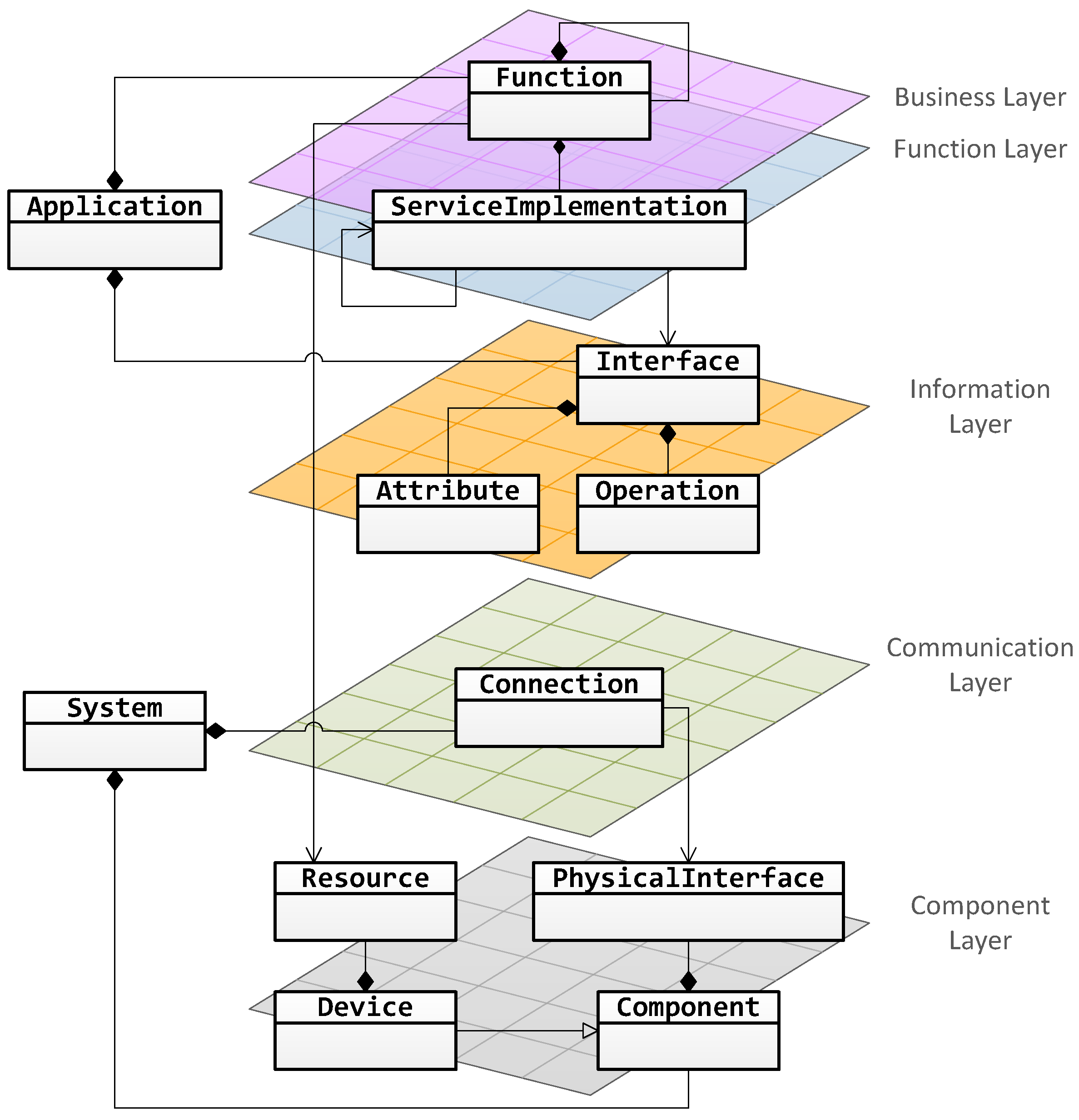
3.3. Power System Automation Language

The main intention with PSAL is to provide a formalized DSL for SGAM compatible use case design. Using PSAL the PIM in Figure 4 is created. This section outlines the main parts of PSAL and how it relates to the SGAM approach with its different layers. In the next section, the grammar and syntax of PSAL is formally defined.
Figure 5 shows the SGAM structure together with a simplified domain model of PSAL represented as a UML class diagram. Since SGAM is divided into different layers this structure should be represented in PSAL as well. The component layer of SGAM is used to describe the hardware components of the system. Generally, these are either power system or ICT components. In PSAL, a general Component is provided. Specializations thereof are used to represent power system and ICT components. Components either already exist in the system or they represent new equipment. The Device represents an ICT controller hardware, where algorithms or software can be executed in so-called Resources. In order to connect Components with each other they can provide one or more PhysicalInterfaces (i.e., power or ICT interfaces). Two PhysicalInterfaces can be connected with each other through a Connection. These parts of PSAL realize requirement ER4.
The ICT Connections are also used to describe the communication layer. In SGAM, this layer is used to specify the communication protocols used in each link. However, the communication layer can also be used to specify other communication related parameters like maximum latency, priorities, VLAN settings, etc. In PSAL, these specifications can be modeled within the ICT Connections and the PhysicalInterfaces. This feature realizes requirement ER7.
Although the communication protocols are specified in the communication layer, the information model that is used is specified in the information layer. With PSAL, a detailed specification of the data exchange is realizable. It should be possible to completely describe the information exchange between two parties. This means it must be possible to specify the format of the exchanged data (i.e., what information model is used) and to specify how the information is exchanged (e.g., if it is published or requested). In PSAL, one of the model parts for this requirement is the information Interface. It allows data to be exchanged either through read and write of Attributes or by calling Operations. With these model parts also requirement ER6 can be realized.
The business layer is used in SGAM to describe business cases and goals. Each business case can in turn be divided into several use cases. This process continues in the function layer, where use cases and sub use cases are divided into functions. In order to model this hierarchy, PSAL provides Functions. Each Function can contain other Functions which makes it possible to model the same hierarchical structure as with business cases, use cases, and functions. This realizes requirement ER1.
Different approaches can be used to model functions and their interaction with each other. The SGAM methodology proposes to describe functions in different UML diagrams (e.g., use case, activity, and sequence diagrams [8]). In order to model function interactions in PSAL, Functions can have ServiceImplementations. Each ServiceImplementation implements an information interface (e.g., an Interface). Thus by connecting ServiceImplementations with each other, it is also possible to model the information flow between the Functions. By using Functions and their ServiceImplementations requirement ER2 is realized.
Additionally to the SGAM methodology, PSAL provides the Application and the System model parts. Together they form a further abstraction layer. The System contains the specification of the component and the communication layers. The Application contains the specification of the business, function, and the information layers. In order to associate the Application model with a System model, Functions are mapped to Resources. A Function-Resource mapping defines in which Resource a specific Function is executed. With this mapping also requirement ER5 is fulfilled.
Using the Functions, a high-level specification of functions can be made. However, in order to automatically generate code for the functions, more details are needed. Since one of the main goals of PSAL is to facilitate code generation the high-level Function specifications will not be enough. One approach could be to only offer a set of predefined Function types that can be combined into an application. This approach offers a clear simplicity, but also a lack of flexibility with respect to new or changing power utility automation functions. Another approach could be to extend PSAL with a programming language that can be used to define Functions. In this approach, the needed flexibility is provided. However, since there already exist a multitude of programming techniques it is not feasible to define a new language for PSAL. Instead, PSAL is combined with an already existing programming technique (see Section 4).
In SGAM, the placement of component and functions into domains and zones is introduced. This placement helps to structure a use case, but is mainly for documentation purposes and has no direct influence on the realization. With a textual implementation of PSAL, the definition of domain and zone through spatial layout is not an option. Nevertheless, it can be done through special comments or through the use of Java-like annotations (e.g., @DER and @Station) in the source code.

3.4. PSAL Definition

Based on the concept in Section 3.2 and the considerations in the previous section, a syntax for PSAL is defined using Extended Backus–Naur Form (EBNF) [38]. A complete overview of the grammar can be found in the Appendix A. As depicted in Figure 5, the two main parts are the System and the Application. These make up the main parts of a PSAL source code document as shown in Listing 1.
Listing 1. Main parts of a PSAL source document.
1 PSAL ::= PsalContent*
2 PsalContent ::= System | Application
This means that a PSAL document can contain zero or more occurrences of PsalContent, which is either a System or an Application. In order to define the domain and zone, a general annotation syntax is defined in Listing 2. This can be used for any model part of PSAL in order to place this part in a certain domain and zone.
Listing 2. Annotations in PSAL.
1 Annotation ::= '@' ID AnnotationParams?
2 AnnotationParams ::= '(' AnnotationParam (',' AnnotationParam)* ')' | '(' ')'
3 AnnotationParam ::= ID

3.4.1. System Model

The System model is a representation of the component and the communication layer in SGAM. The System is defined in Listing 3. Each System has a unique identifier and can contain zero or more SystemComponents. These are either a Component (see Listing 4) or a Connection (see Listing 8).
Listing 3. The System model.
1 System ::= 'system' ID '{' SystemContent* '}'
2 SystemContent ::= Component | Connection
Different types of Components can be defined, as is seen in Listing 4. The main focus of this work was on the ICT components and how these can be programmed.
Listing 4. The Component model
1 Component ::= ICTComponent | ElectricalComponent
2 ICTComponent ::= Device | OtherICTComponent
A programmable ICT component is represented by the Device, see Listing 5. A Device has a unique identifier and contains zero or more Resources and/or PhysicalInterfaces.
Listing 5. The Device model.
1 Device ::= 'device' ID '{' DeviceContent* '}'
2 DeviceContent ::= Resource | PhysicalInterface
3 Resource ::= 'resource' ID
The PhysicalInterface can either be an ICTInterface or an ElectricalInterface, see Listing 6. It can also contain IDValuePairs, a simple construct in order to define values for settings like an IP address or a port (see Appendix A).
Listing 6. The PhysicalInterface model.
1 PhysicalInterface ::= PowerInterface | ICTInterface
2 PowerInterface ::= 'power' ID ('{' IDValuePair* '}')?
3 ICTInterface ::= ICTInterfaceType ID ('{' IDValuePair* '}')?
4 ICTInterfaceType ::= 'ethernet' | 'wireless' | 'serial' | 'analogue' | 'digital'
Apart from the Device, two other components are defined in Listing 4: the ElectricalComponent and the OtherICTComponent. These are defined in the same way with a type, an identifier, and optional settings (i.e., IDValuePairs), see Listing 7.
Listing 7. Definition of other components.
1 OtherICTComponent ::= OtherICTComponentTypes ID ('{' IDValuePair* '}')?
2 OtherICTComponentTypes ::= 'gateway' | 'switch' | 'router'
3 ElectricalComponent ::= ElectricalComponentType ID '{' ElectricalComponentContent* '}'
4 ElectricalComponentType ::= 'transformer' | 'DER' | 'line' | 'breaker' | 'load' | 'busbar' | 'slack'
5 ElectricalComponentContent ::= PhysicalInterface | IDValuePair
As shown in Figure 5, Connections between the PhysicalInterfaces of the Components can be defined. To define a Connection the definition in Listing 8 is used. Generally, the QualifiedNames must match PhysicalInterfaces defined in the scope of the System. However, some exceptions are valid: between ElectricalComponents it is allowed to define Connections directly, and Connections directly to/from OtherICTComponents are also allowed. Optionally, a Connection can also be configured with user defined settings (i.e., IDValuePair). This can, for example, be communication network settings.
Listing 8. The Connection model.
1 Connection ::= 'connect' QualifiedName 'with' QualifiedName ('{' IDValuePair* '}')?

3.4.2. Application Model

The Application model in Figure 5 contains two main parts: Functions and information Interfaces. Furthermore, Connections between ServiceImplemenations can be used to model the information exchange between Functions. The Functions and the Connections are used to model the business and the function layers of SGAM, and the Interfaces model the information layer. The Application is defined in Listing 9.
Listing 9. The Application model.
1 Application ::= 'application' ID '{' ApplicationContent* '}'
2 ApplicationContent ::= Function | Connection | <module>
The information Interface from Figure 5 is modeled using the grammar of OMG IDL [39]. The main idea with the Interface is to model the information that is exchanged between the Functions. However, this is a well known problem in computer science, where Interface Description Languages (IDL) (e.g., [39,40]) are used to described the information in a platform-independent way. In a second step, the interface description using the IDL can be generated into specific code, for example Java or C++. After comparing the syntax and features of different IDLs, the OMG IDL [39] was chosen as a suitable IDL for PSAL. Therefore the <module> of the ApplicationContent in Listing 9 is the same as the <module> of OMG IDL (which also explains the change of the description syntax). For completeness, the parts of OMG IDL that are of interest for this paper are defined in Appendix A. For PSAL, mainly the <interface> and the <event> elements are used. The Interface class in Figure 5 is a conceptual representation of the <interface> from OMG IDL.
The information defined using OMG IDL can be used by the Functions. In Listing 10, the Function model is defined. Each Function has a unique identification, a possible mapping (see Listing 12), and it consists of other Functions, Connections and/or ServiceImplementations.
Listing 10. The Function model.
1 Function :: = 'function' ID (FunctionMapping)? '{' FunctionContent* '}'
2 FunctionContent ::= Function | Connection | ServiceImplementation
A ServiceImplementation implements a service type: an <interface> or an <event>. ServiceImplementations can be requested or provided by a Function. Depending on the service type the syntax is a bit different, as seen in Listing 11. To define a service type, the QualifiedName of a ServiceImplementation must match a defined <interface> or <event>.
Listing 11. The ServiceImplementation model.
1 ServiceImplementation ::= ProvidedService | RequestedService
2 ProvidedService ::= ProvidedIDLInterface | ProvidedIDLEvent
3 RequestedService ::= RequestedIDLInterface | RequestedIDLEvent
4 ProvidedIDLInterface ::= 'provides' QualifiedName ID ('{' ParameterAssignment* '}')?
5 ParameterAssignment ::= QualifiedName '=' ValueLiteral
6 RequestedIDLInterface ::= 'requests' QualifiedName ID ('{' ParameterAssignment* '}')?
7 ProvidedIDLEvent ::= 'emits' QualifiedName ID ('{' ParameterAssignment* '}')?
8 RequestedIDLEvent ::= 'consumes' QualifiedName ID ('{' ParameterAssignment* '}')?
As represented in Listing 9 and in Listing 10, both the Application and the Function can contain Connections. In both cases, the syntax is the same as defined in Listing 8. In the Application, a defined Connection connects a requested service with a provided service. The same applies to Connections defined in a Function but with the additional possibility to connect a provided/requested service of a contained Function with a provided/requested service of the containing Function. In all cases, the connected ServiceImplementations must be of the same service type.
To connect the Application with a System, the Functions of the Application must be assigned to the Devices defined in the System. This is done by mapping a Function to a Resource in a Device. When a Function is mapped to a Resource, all provided and requested services of this Function are also mapped to the Resource. Consequently, these services are also available on any ICTInterface of the Device. Listing 12 shows how a mapping is defined, where the QualifiedName of the FunctionMapping must match a defined Resource.
Listing 12. The FunctionMapping model.
1 FunctionMapping ::= 'at' QualifiedName

4. Mapping a Selected Programming Technique to PSAL

With PSAL, use cases according to SGAM can be specified, as described in Section 3.2. This specification covers the modeling and design phase in Figure 4. But as already discussed in Section 3.3, the Function model of PSAL is only intended for the functional specification (see requirement ER2). The details of each Function must be provided by another programming technique. However, before the details of Functions can be specified, a suitable programming technique must be chosen and mapped to PSAL. In this work, a mapping between a programming technique P and PSAL is defined as a specification of how the Functions of PSAL are implemented using P . In order to successfully map a programming technique to PSAL, the following steps are followed:
  • Choosing a programming technique P
  • Define how Functions are implemented using P
  • Define how ServiceImplementations are implemented using P
Furthermore, the general information description model in PSAL can be used to describe existing information models. This is done by mapping the existing information model to <interface>s and <event>s. The programming technique P and the information models make up the PSM in Figure 4.
This work shows how the programming technique IEC 61499 is mapped to PSAL. It is also shown how IEC 61850 is mapped to the PSAL information model. In order to help the reader to distinguish between elements from the different models they are differently emphasized in the following sections. Any model elements from PSAL are emphasized with a teletype font (e.g., Function). Model elements from IEC 61499 are emphasized with a sans-serif font (e.g., SubApp499) and elements from IEC 61850 are emphasized with a slanted font (e.g., LDevice850).

4.1. Choosing a Suitable Programming Technique

First of all a suitable programming technique must be chosen. Based on the definition of PSAL the following main concepts should either be directly supported or implementable by the technique:
  • Software components: The Functions in PSAL are simple software components, which means that this concept should be supported. Components should also be able to contain other components, in order to model different levels of detail.
  • Information services: Services must be representable by the programming technique. The services can be implemented in different ways, but important is that information can be exchanged between the software components.
  • Software component mapping: Once a software component is described, it should be mappable to a system component. This mapping identifies on which hardware the software is executed.
  • Deployment: Mapped software components should be easily deployable. This deployment can be either manual or (semi-)automatic.
  • Support for multiple protocols: Different communication protocols should be supported by the technique. The more supported protocols, the higher the interoperability with other systems.
Apart from the interoperability with PSAL, each actor (see Table 1) must consider his/her own platform-specific requirements. Depending on the platform hardware and/or software, some programming techniques may not be suitable. For example, a system only consisting of embedded controllers with limited memory capabilities may exclude many high-level programming techniques. On the other hand, if a certain programming technique has already been used for implementations of a system, this technique may be the best choice for compatibility reasons.
For this work, IEC 61499 is chosen as programming technique. It has already been discussed as one possible solution for implementing smart grid applications in a standardized way [41,42]. Furthermore, IEC 61499 provides a platform-independent modeling concept. Since it also allows design on multiple levels it can be used by many of the actors in Table 1. The FBs499 from IEC 61499 can be used to represent the software components. The interfaces of each FB499 can represent service implementations. An advantage of IEC 61499 is that it inherently supports the mapping of FBs499 to hardware devices. Once a mapping has been done, IEC 61499 also supports the deployment of these FBs499 with a simple download. Thus, the last two phases of the rapid engineering methodology in Figure 4 are supported.

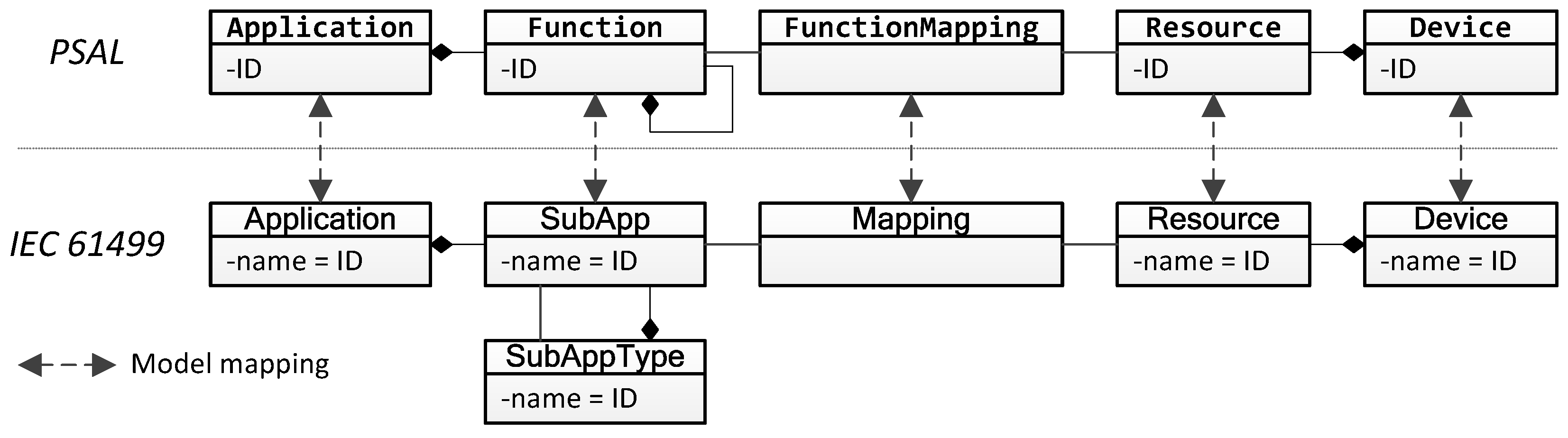
4.2. Mapping IEC 61499 to the Function Model of PSAL

Once a programming technique has been chosen it must be mapped to the Function model of PSAL. This means that one or more entities of the technique are used to represent the software component, represented by the Function in PSAL. If possible a one-to-one mapping is to prefer since this also allows for a simple round-trip transformation.
There already exist work where IEC 61499 has been used for implementing smart grid functionality, especially together with IEC 61850. Andrén et al. present guidelines for implementing smart grid functions using these two standards [43,44], where subapplications and adapters (i.e., SubApps499 and Adapters499) are used to model IEC 61850 IEDs. Since an IED merely defines an number of interfaces (i.e., the LNs) but no real functionality, it is very similar to the Function specifications with PSAL. By taking advantage of this similarity, the modeling guidelines from [43,44] can also be applied in this work.
Consequently, each Function of PSAL is mapped to a SubApp499 in IEC 61499. The SubApp499 is defined by a SubAppType499. Since a SubAppType499 can also contain other SubApps499, it possible to model multiple levels of Functions using IEC 61499. The overall mapping between PSAL and IEC 61499 is shown Figure 6.
The mappings between the other model objects are straightforward. Since IEC 61499 also has a system model it is possible to find a model mapping for the Devices and Resources of PSAL. As already mentioned, IEC 61499 supports mapping of FBs499/SubApps499 to Resources499. Using this opportunity, the FunctionMapping of PSAL can be directly represented as a Mapping499 in IEC 61499. This provides a direct implementation of requirement ER5.
With the mapping between PSAL and IEC 61499, two important parts of the PSM as shown in Figure 4 can be completed. The SubAppType499 allows the engineer to implement Functions in detail, which completes the function generation part. It also allows the realization of requirement ER3. The second part completed is the generation of executable code in Figure 4. This code is composed by the Resources499 containing FBs499 and SubApps499.

4.3. Describing Service Implementations in PSAL Using IEC 61499

Once a mapping for the Function model has been found, the Functions must be able to exchange information. This means that ServiceImplementations of Functions need a representation in the chosen programming technology. Furthermore, the Connections between ServiceImplementations also need a mapping. After the Functions of an Application have been assigned to a Resource with a FunctionMapping there is a difference between internal and external Connections. Internal Connections connect Functions in the same Resource. External Connections connect Functions in different Resources.
With IEC 61499, the ProvidedServices are implemented as Sockets499, and the RequestedServices as Plugs499. Each Plug499 and Socket499 in IEC 61499 is defined by an Adapter499 type. Adapters499 encapsulate a plug/socket behavior with a bidirectional communication between software components [45]. Since each ServiceImplementation is defined by either an <interface> or an <event>, a mapping is also needed between these and the Adapter499.
In Figure 7, an example is shown to illustrate the mapping between an <interface> and a corresponding Adapter499. The <interface> can contain attributes (<attr_decl>) and operations (<op_decl>). The type of an attribute can either be a simple type or an already defined type (e.g., another <interface>). All attributes that are of an already defined type are represented as a Plug499 interface of the Adapter499, see the derControls Plug499 in Figure 7b. Any attributes that have a simple type are transformed into a set of events and data ports. All attributes in PSAL are automatically assigned a get-function. Non-readonly attributes are also assigned a set-function. To represent this for the Adapter499, a GET-Event499 is created for each attribute, and a SET-Event499 for non-readonly attributes, see Figure 7. Operations in PSAL on the other hand, define a callable function, and can have both inputs (notated with in), outputs (notated with out), and a return value. The operation getEnergy, defined in Figure 7a, is mapped to an Event499 with the same name as the operation. This event is associated with two data ports: from and to in Figure 7b. Once the operation has finished, a CNF-Event499 is triggered.
The <event>s of PSAL are also mapped to Adapters499, see Figure 8. Since an <event> only represents a one-way information exchange its implementation as Adapter499 is simplified, with only one Event499. The <state_member>s of the <event> are mapped to data ports of the Adapter499.
In IEC 61499, connections between FBs499 that are mapped to different Resources499 may need extra attention during deployment. These connections need to be split up using explicit communication FBs499. The IEC 61499 standard provides two generic communication patterns: client/server for bidirectional connections and publish/subscribe for unidirectional connections [18]. The service types in PSAL can also be mapped to the same patterns. The <interface> models a typical client/server connection, where the client calls the operations of an <interface> and gets/sets the attributes. In order to model publish/subscribe relationships, the <event> can be used. An <event> is emitted by a publisher, and consumed by a subscriber.

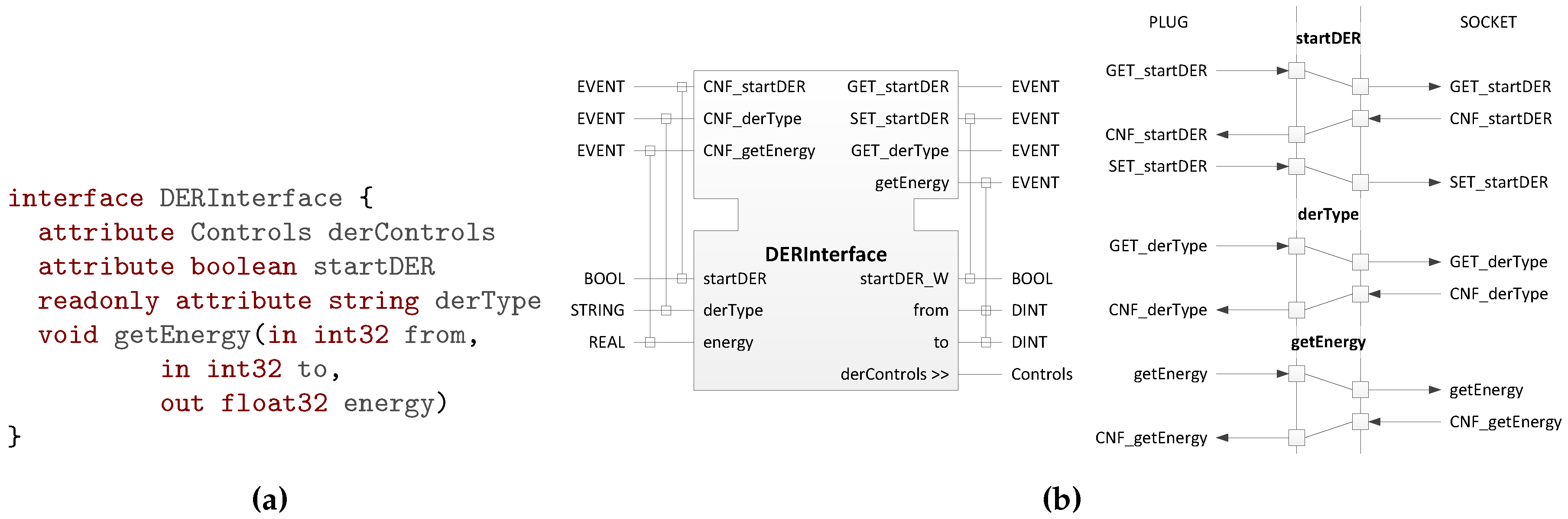
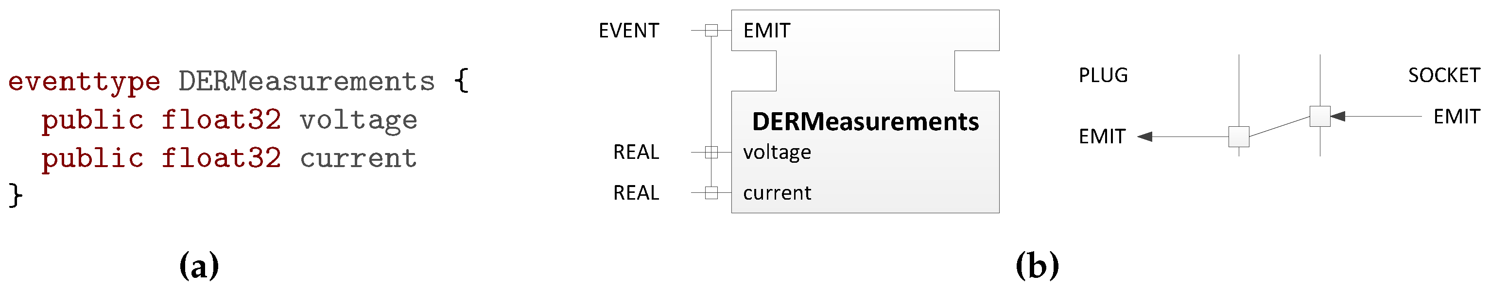
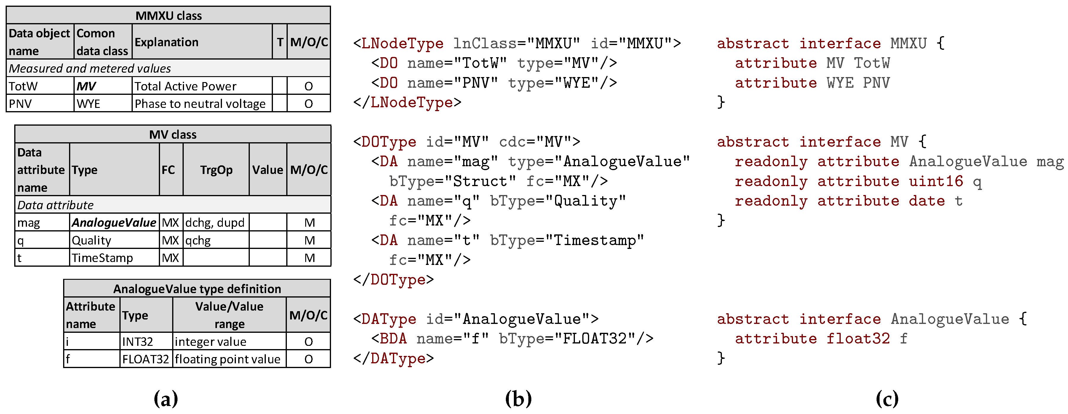
4.4. Mapping IEC 61850 to Interfaces and Events in PSAL

Once the ServiceImplementations, the <interface>s, and the <event>s can be represented by IEC 61499, different information models can be mapped to the PSAL information model (i.e., to <interface>s and <event>s). This allows the user to model communication with different already existing protocols (e.g., IEC 61850, SunSpec/Modbus).
As an example of how information models can be mapped to the PSAL generic information model, IEC 61850 is used. The IEC 61850 standard defines LN classes for multiple applications. In the standard, these classes are defined as tables (see Figure 9a for an excerpt of the MMXU class from [21]). Moreover, IEC 61850 also provides SCL, an XML based description language used to write configuration files. An SCL file for an IED specifies which LN classes are provided by this IED. For each provided LN, the SCL file also includes a type definition—an LNodeType850. Since data objects of an LN class can be optional, the LNodeType850 defines which of these are mandatory for the current configuration. Figure 9b shows the SCL definition of MMXU. Only one of the optional attributes in the AnalogueValue DAType850 is used.
With SCL as foundation, a mapping from IEC 61850 to the PSAL <interface>s can be formulated. Apart from the LNodeType850 SCL uses DOTypes850 for Common Data Classes (CLC), and DATypes850 for Data Attribute (DA) types. For these three types, the same mapping approach can be used—each type is mapped to an <interface>. The types in IEC 61850 contains objects: data objects (DO850), DAs850, or basic DAs850 (BDAs850). These are mapped to <attr_spec>s (i.e., attributes) in PSAL. In Figure 9c, the PSAL definition of an MMXU is shown.
With this mapping, all LN classes that are defined in the IEC 61850 standard can be imported and represented in PSAL. The mapping also makes it possible to import a whole SCL file into a corresponding PSAL model. The other way around, if IEC 61850 <interface>s are used in a PSAL model (i.e., as in Figure 9c), these can also be exported to an SCL file. Such an SCL file is one possible communication code, as shown in Figure 4. This means, with the usage of IEC 61499 for the component model and protocol mappings like IEC 61850 the last two phases, code generation and deployment can be completed as well.

5. Use Case Example

In order to show how the rapid engineering methodology is used, a use case example is modeled and implemented. As a use case example, a slightly modified version of the use case Integrated Volt VAr Control Centralized is considered in this work [46]. It is a typical use case for distribution network operation, where a central system manages and controls Volt-VAR Controller (VVC) devices in a regional distribution network. An overview of the use case is provided in Figure 10. It mainly applies to the actors A1-Utility Operator and A2-System Integrator.

5.1. Use Case Analysis

This control implementation uses a centralized approach where the actual intelligence of the volt-VAr control lies within the Distribution System Operator (DSO), and all actions are routed through the DSO SCADA (D-SCADA) system. The controller devices in the field (i.e., the Voltage Regulator Controller, the Capacitor Bank Controller, the DER Controller, and the End-of-Line Monitor) send measurements, and the Circuit Reconfiguration Controller sends the grid status to the Distribution RTU. The Distribution RTU aggregates this information and forwards it to the D-SCADA system. The Powerflow Module acquires its necessary load-flow information and passes it on to the D-SCADA. Thereupon, the D-SCADA forwards all vital information to the VVC. The VVC computes new set points for the controller devices. These are forwarded by the D-SCADA and the Distribution RTU to the field devices. All important data are continuously sent to the Distribution Historian [46].
In order to simplify the example for this paper, the Distribution Historian, the Powerflow Module, and the Circuit Reconfiguration Controller are excluded from the use case modeling and realization. Also, from the field controllers only the DER Controller is modeled in detail. Since the other field controllers are modeled in a similar way, the use case can be easily extended to include them as well.

5.2. Business and Function Layers Design

In the SGAM approach, the business and function layers should provide a high-level overview of the business cases and the main functions of the use case. As the use case does not provide any direct information about business cases or goals, these will not be covered in the modeling. Instead, the functions of the use case are directly derived from the use case analysis in Section 5.1.
The specification of the Functions also needs include a first draft of the necessary information exchange. Therefore, <interface> and <event> types are defined, which provide a generic representation of the information that is exchanged in the use case. The formal data model for the information is defined in the design of the information layer.
The result is depicted in Listing 13. An Application named VoltVArControlCentralized is defined. Inside the Application, seven different Functions are specified. The information that is exchanged is specified in two <module>s: DERInformation, with the VoltVAr and DERInformation <interface>s, and FieldInformation, with the GridStatus <event> and the Controls <interface>. The <interface>s and <event> are provided and requested by the Functions through their ServiceImplementations. Finally, the information exchange between the Functions is specified by Connections between the ServiceImplementations. For the Functions VoltageRegulatorController, CapacitorBankController and EndOfLineMonitor no details are provided.
Listing 13. Business and function layer model for the example use case.
 1 application VoltVArControlCentralized {
 2   module DERInformation {
 3     interface VoltVAr {
 4       /* Voltage set points for droop curve */
 5       attribute float32 v1, v2, v3, v4
 6       /* Reactive power set points for droop curve */
 7       attribute float32 q1, q2, q3, q4
 8       attribute boolean activateVoltVAr
 9     }
10     interface DERMeasurements {
11       readonly attribute float32 voltage, activePower
12   }}
13   module FieldInformation {
14     eventtype GridStatus {
15       /* Voltage measurements from field devices (p.u.)*/
16       public float32 vVRC, vCBC, vEOLM, vDER
17     }
18     interface Controls {
19       attribute DERInformation.VoltVAr derVoltVar
20   }}
21 
22   function VoltVArController {
23     consumes FieldInformation.GridStatus gridStatus
24     requests FieldInformation.Controls fieldControls
25   }
26   function DSCADA {
27     consumes FieldInformation.GridStatus gridStatusRTU
28     requests FieldInformation.Controls fieldControlsRTU
29     emits FieldInformation.GridStatus gridStatus
30     provides FieldInformation.Controls fieldControls
31   }
32   function DistributionRTU {
33   requests DERInformation.VoltVAr derControls
34     requests DERInformation.DERMeasurements derMeasurements
35     emits FieldInformation.GridStatus gridStatus
36     provides FieldInformation.Controls fieldControls
37   }
38   function DERController {
39     provides DERInformation.VoltVAr voltVar
40     provides DERInformation.DERMeasurements measurements
41   }
42   function VoltageRegulatorController {...}
43   function CapacitorBankController {...}
44   function EndOfLineMonitor {...}
45 
46   connect DistributionRTU.derControls with DERController.voltVar
47   connect DistributionRTU.derMeasurements with DERController.measurements
48   connect DSCADA.gridStatusRTU with DistributionRTU.gridStatus
49   connect DSCADA.fieldControlsRTU with DistributionRTU.fieldControls
50   connect VoltVArController.gridStatus with DSCADA.gridStatus
51   connect VoltVArController.fieldControls with DSCADA.fieldControls
52  }
Listing 13 only provides an initial specification of the Functions, which is also the intention of the initial design. Once a final version of the use case specification is completed the Functions are defined using IEC 61499. This step is described in Section 5.5.

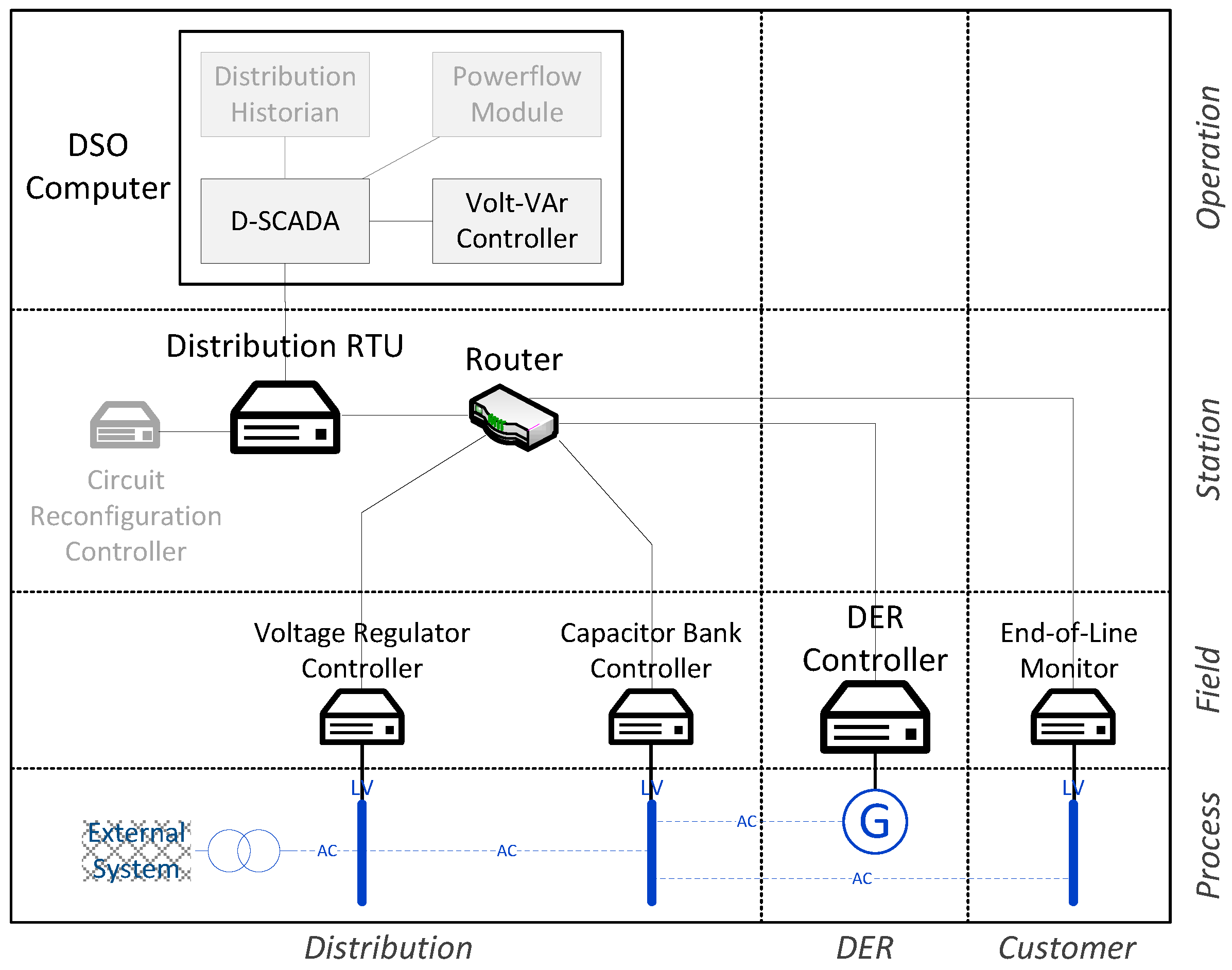
5.3. Component Layer Design

The next step in the SGAM methodology is the development of the component layer. With PSAL, this step includes the definition of the System model, where each component participating in the use case is defined. In Listing 14, the System model for the example use case is shown. The listing also shows how the components are placed in their corresponding SGAM zone and domain using annotations (e.g., @Distribution @Operation). For the VoltageRegulatorController, the CapacitorBankController, and the EndOfLineMonitor no details are provided.
Listing 14. System model for the use case example.
 1 system DistributionSystemVV {
 2   /* ICT Components */
 3   @Distribution @Operation
 4   device DSOComputer {
 5     ethernet eth0 {ip = "10.0.0.1"}
 6     resource SCADA
 7     resource VoltVAr
 8   }
 9   @Distribution @Station
10   device DistributionRTU {
11     ethernet eth0 {ip = "10.0.0.2"}
12     ethernet eth1 {ip = "101.0.0.1"}
13     resource RTUResource
14   }
15   router StationRouter
16   @Distribution @Field
17   device VoltageRegulatorController {...}
18   device CapacitorBankController {...}
19   @DER @Field
20   device DERController {
21     ethernet eth0 {ip = "101.0.0.3"}
22     ethernet eth1 {ip = "192.168.0.2"}
23     resource AncillaryServices
24   }
25   @Customer @Field
26   device EndOfLineMonitor {...}
27 
28   /* Power System Components */
29   @Distribution @Process
30   slack ExternalSystem  transformer MVLV  busbar LV1  line LV1LV2  busbar LV2 line LV2LV3
31   @Customer @Process
32   busbar LV3
33   @DER @Process
34   DER DERGenerator {
35     ethernet eth0 {ip = "192.168.0.1"}
36   }
37   }
38   connect DistributionRTU.eth0 with DSOComputer.eth0
39   connect DistributionRTU.eth1 with StationRouter
40   connect DERController.eth0 with StationRouter
41   connect DERController.eth1 with DERGenerator.eth0
42   connect MVLV with ExternalSystem
43   connect LV1 with MVLV
44   connect LV1LV2 with LV1
45   connect LV2 with LV1LV2
46   connect DERGenerator with LV2
47   connect LV2LV3 with LV2
48   connect LV3 with LV2LV3
49 }
The System contains both ICT components and power system components. The ICT components consist of Devices and one router. Each Device provides one or more ICTInterfaces, where the IP address is specified. It is also possible to specify other settings in the same manner as the IP address (e.g., macAddress = "00:0c:a8:..."). At this point in the modeling phase, these specifications are completely platform-independent. It is the task of the programming technique (i.e., IEC 61499) to create platform-specific descriptions of the specifications, which can be used to configure the corresponding field device. The DSOComputer Device defines two Resources: SCADA and VoltVAr. This shows how one device can be split up into different computing resources and how this can be used to group different functionality.
Once the component layer is defined with the System model, the Functions defined in the Application can be mapped to components and resources. In this example, the mapping is straightforward. Based on Figure 10, the Function declarations from Listing 13 are extended with mapping information, as seen in Listing 15.
Listing 15. The Functions from Listing 13 are mapped to the Resources in Listing 14.
   @@ -21,3 +21,3 @@
21 - function VoltVArController {
22 + function VoltVArController at DistributionSystemVV.DSOComputer.VoltVAr {
23     consumes FieldInformation.GridStatus gridStatus
   @@ -25,3 +25,3 @@
25   }
26 - function DSCADA {
26 + function DSCADA at DistributionSystemVV.DSOComputer.SCADA {
27     consumes FieldInformation.GridStatus gridStatusRTU
   @@ -31,3 +31,3 @@
31   }
32 - function DistributionRTU {
32 + function DistributionRTU at DistributionSystemVV.DistributionRTU.RTUResource {
33     requests DERInformation.VoltVAr derControls
   @@ -37,3 +37,3 @@
37   }
38 - function DERController {
38 + function DERController at DistributionSystemVV.DERController.AncillaryServices {
39     provides DERInformation.VoltVAr voltVar

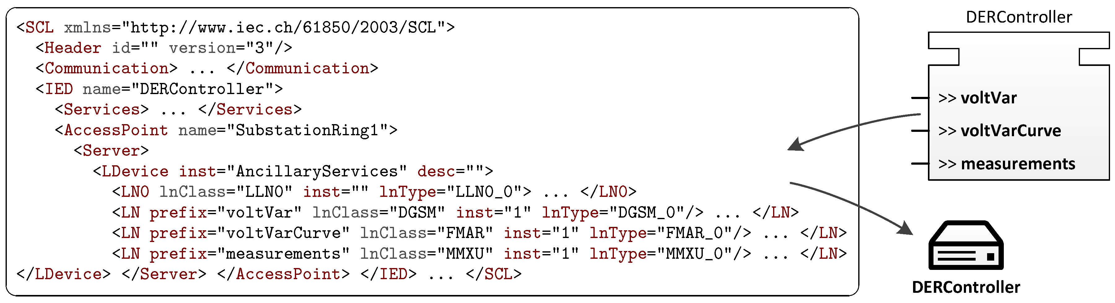
5.4. Information and Communication Layers Design

In SGAM, the goal of the information layer is to describe the information flow between the different components of the tackled use case. The information can be provided using different data models (e.g., IEC 61850, Common Information Model (CIM)). Similarly, the communication layer in SGAM should provide a detailed picture of the communication infrastructure and the type of communication protocol that is used [8]. Also in PSAL this information needs to be provided. As seen from Listing 13, an initial definition of the information layer (i.e., the definition of <interface>s and <event>s) is done in the design of the business and function layers (see Section 5.2). This is also needed in order to provide a general picture of the interaction between Functions. However, the defined information is only using a generic data model.
In order to use other data models, a protocol mapping is used. Section 4.4 describes how this is done for IEC 61850. As depicted in Figure 9c, the MMXU <interface> is declared as abstract. This means that it cannot be directly implemented by a ServiceImplementation. Instead, an abstract <interface> can only be implemented through inheritance by a non-abstract <interface>. Both <interface>s and <event>s can inherit, which means that all attributes, operations, and/or state members defined in the parent are also available at the derived child.
The possibility for services to inherit also provides a solution for how ServiceImplementations can use different data models. The MMXU <interface> from Figure 9c can be used as a parent for the DERMeasurements <interface> from Listing 13. Consequently, all ServiceImplementations that now implement DERMeasurements (i.e., DistributionRTU.derMeasurements and DERController.measurements in Listing 13) also have access to the attributes defined by the MMXU <interface>. To complete the update, the voltage and acivtePower attributes should be removed from DERMeasurements, since MMXU already has attributes for voltage and active power measurements.
As for the measurements, the VoltVAr <interface> in Listing 13 can also be changed to an IEC 61850 <interface>. In this case, VoltVAr inherits from the DGSM LN (DGSM: Issue “operational mode control” command). Additionally a new <interface> is added inheriting from the FMAR LN (FMAR: Establish mode curves and parameters). Both DGSM (used to activate the volt-VAr control) and FMAR (used to define a volt-VAr droop curve) are defined in IEC 61850-90-7 technical report [47]. All the changes made to the interfaces are shown in Listing 16.
Listing 16. DER <interface>s from Listing 13 inherits from IEC 61850 <interface>s.
   @@ -2,12 +2,6 @@
 2   module DERInformation {
 3 -   interface VoltVAr {
 4 -    /* Voltage set points for droop curve */
 5 -    attribute float32 v1, v2, v3, v4
 6 -    /* Reactive power set points for droop curve */
 7 -    attribute float32 q1, q2, q3, q4
 8 -    attribute boolean activateVoltVAr
 9 -   }
10 -   interface DERMeasurements {
11 -    readonly attribute float32 voltage, activePower
12 - }}
 3 +   interface VoltVAr : DGSM { }
 4 +   interface VoltVArCurve : FMAR { }
 5 +   interface DERMeasurements : MMXU { }
 6 + }
 7  module FieldInformation {
   @@ -18,3 +12,4 @@
12     interface Controls {
13      attribute DERInformation.VoltVAr derVoltVar
14 +      attribute DERInformation.VoltVArCurve derVoltVArCurve
15  }}
The changes to the interfaces also require some adaptions to the ServiceImplementations of the Functions in Listing 13. A new <interface> was added to the DERInformation <module>. This must be provided by the DERController Function and should also be requested by the DistributionRTU. The changes are applied with the update in Listing 17.
Listing 17. The Functions from Listing 13 are update to implement the new <interface>.
   @@ -32,3 +27,4 @@
27   function DistributionRTU at DistributionSystemVV.DistributionRTU.RTUResource {
28    requests DERInformation.VoltVAr derControls
29 +    requests DERInformation.VoltVArCurve derCurve
30    requests DERInformation.DERMeasurements derMeasurements
   @@ -38,3 +34,4 @@
34   function DERController at DistributionSystemVV.DERController.AncillaryServices {
35    provides DERInformation.VoltVAr voltVar
36 +    provides DERInformation.VoltVArCurve voltVarCurve
37    provides DERInformation.DERMeasurements measurements
   @@ -46,2 +43,3 @@
43    connect DistributionRTU.derControls with DERController.voltVar
44 +    connect DistributionRTU.derCurve with DERController.voltVarCurve
45    connect DistributionRTU.derMeasurements with DERController.measurements
Apart from the data models, different protocols, working on different Open Systems Interconnection (OSI) layers, can be used. In PSAL, the lower OSI layers (layers 1-4) can be defined for each ICTInterface and for ICT Connections. For the upper OSI layers (layers 5-7) definitions or configurations are specified, if they are needed, in the ServiceImplementations.

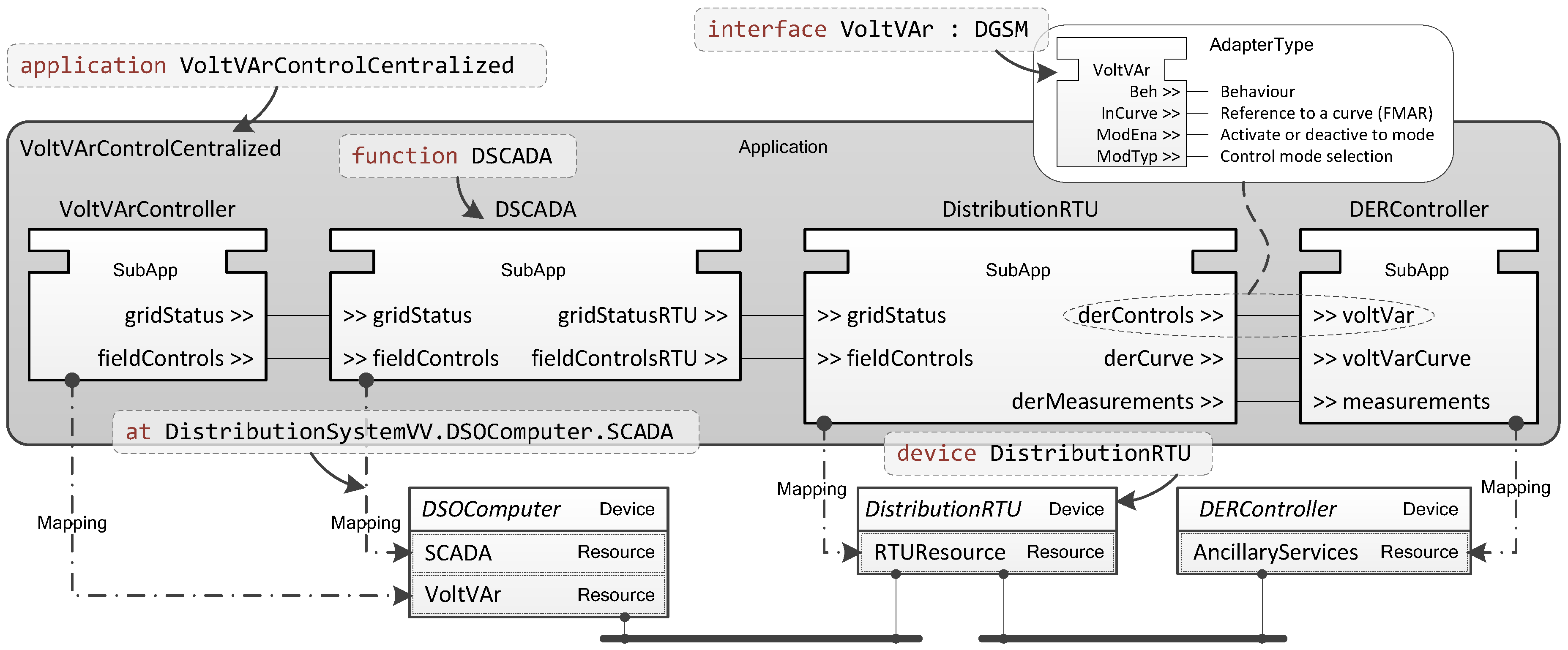
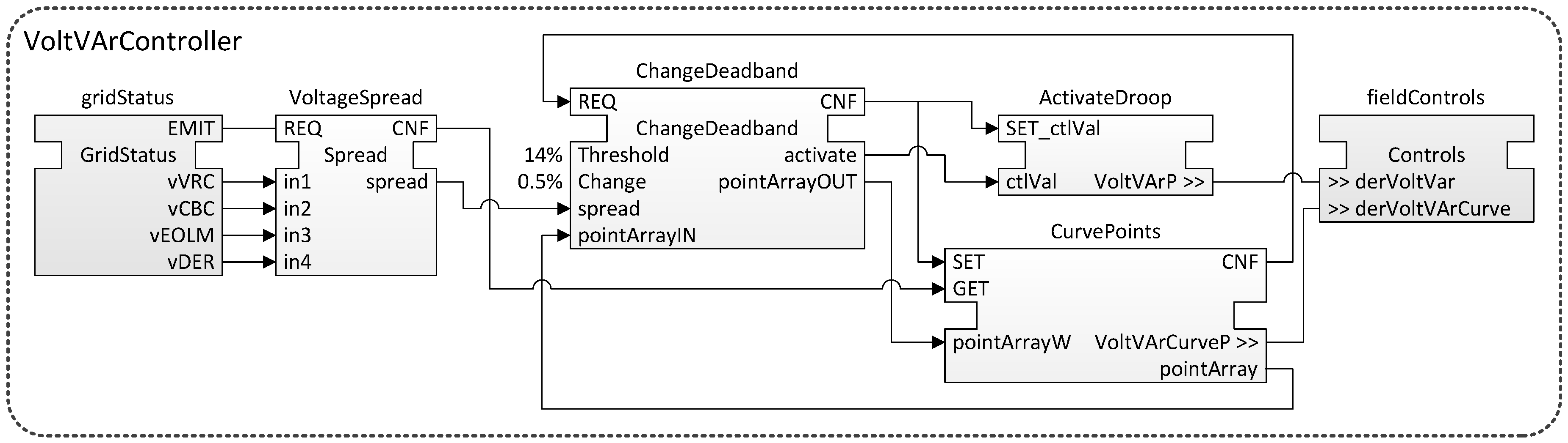
5.5. Business and Function Layers Revisited: Transformation to IEC 61499

Once the Application and the System have been specified and the correct data model has been defined for the <interface>s and <event>s, a transformation is made into the chosen programming technique. In this case, this means a transformation to IEC 61499 using the rules as defined in Section 4.2. After the transformation, IEC 61499 is used to define the behavior of each Function.
The first step is to transform the Application and System into an equivalent IEC 61499 Application499 and system model. To do this the mapping from Figure 6 is used. The result of this transformation is shown in Figure 11.
SubApps499 are generated representing the Functions in Listing 13. Furthermore each SubApp499 will have Plugs499 and Sockets499 representing the ServiceImplementations of the original Functions. The Sockets499 and Plugs499 are connected with each other through adapter connections. Also each Socket499/Plug499 is defined by an Adapter499, transformed from an <interface> using the mappings in Figure 7 and Figure 8. Together the connected SubApps499 compose the resulting Application499, VoltVArControlCentralized.
Figure 11 also shows how the System from Listing 14 is transformed into a corresponding IEC 61499 system model with Devices499 and Resources499. Finally, it also illustrates how the SubApps499 are assigned to their respective Resources499 (e.g., the DSCADA SubApp499 is mapped to the SCADA Resource499 in the DSOComputer Device499).
The example addresses how transformations between PSAL Functions and IEC 61499 SubApps499 are made. However, the resulting SubApps499 still do not contain any content. Of course the Functions from Listing 13 can contain other Functions (which would be transformed to SubApps499 contained by the current SubApps499 in Figure 11) but they would still not contain any logic. One possibility is that some of the specified Functions are already implemented (i.e., they already exist in the field). If that is the case the SubApps499 representing these Functions do not need to be implemented. For the other SubApps499, the next step of the use case modeling is to provide them with logic.
For this example, it is assumed that only the logic in the VoltVarController SubApp499 needs to be created, and that the other SubApps499 have already been implemented. Each SubApp499 is defined by a SubAppType499 and in this type the logic is defined.
Two adapter Plugs499 are implemented by the VoltVArController. The gridStatus Plug499 requests the important measurements from the grid, and the fieldControls Plug499 requests the control interfaces from the field devices (i.e., the DERController, the VoltageRegulatorController, and the CapacitorBankController). Using the grid measurements, the voltage spread (i.e., the difference between highest and lowest voltage measurement) in the grid is calculated. In case of a too high spread, new voltage set points for the field devices are calculated. For the DERController this means that a new volt-VAr droop curve is calculated [37].
A new volt-VAr droop curve is easily calculated by changing the dead band of the curve. This means that if the voltage spread is too high the dead band is decreased. In Figure 12, the implementation of the VoltVArController SubAppType499 from Figure 11 is shown. Left and right in the figure the Plugs499 of VoltVArController are shown as adapter FBs499 (i.e., the gridStatus and fieldControls FBs499). The VoltVArController SubAppType499 also contains two other SubApps499: ActivateDroop and CurvePoints. These SubApps499 are only used to access the important data for this use case. The CurvePoints SubApp499 provides the points of the droop curve as an array, with pairs of volt-VAr values (i.e., pointArray for reading and pointArrayW for writing).
Every time a new EMIT event is emitted (i.e., new measurements are published by DSCADA), the voltage spread is calculated from the new measurements. Thereafter, the current droop curve points are requested from the DER. Once these arrive they are forwarded, together with the voltage spread, to the ChangeDeadband FB499. If the spread is higher than the allowed Threshold the dead band of the droop curve is decreased by the Change amount. Next, the ChangeDeadband FB499 sends the new droop curve values to the DERController, and if needed activates the volt-VAr control.

6. Prototypical Implementation and Laboratory Validation

This section describes how a prototypical framework implementation was made for the methodology described above. Furthermore, a laboratory validation is presented, which shows how the implemented framework can be effectively used to implement and execute laboratory tests.

6.1. Prototypical Implementation

In order to create a framework capable of all things presented for the methodology above, three main parts are needed. First, PSAL must be implemented such that power utility automation use cases can be modeled. PSAL was implemented using the Xtext environment for the Eclipse IDE [48].
Secondly, PSAL should be extended with IEC 61499 capabilities to allow the implementation of PSAL Functions. For this purpose, the 4DIAC-IDE [49] was chosen, an open-source IEC 61499 compatible development environment. Since the 4DIAC-IDE is also based on the Eclipse IDE it was possible to create one environment capable of both use case modeling with PSAL and implementations in IEC 61499. 4DIAC also provides a runtime environment for execution of IEC 61499 control applications.
As already discussed in Section 4.3, connections between FBs499 or SubApps499 which are mapped to different Resources499s may need extra attention. In the case with 4DIAC, such connections can be automatically split up with generic communication FBs499s [50]. However, the current support in 4DIAC is limited. Therefore, it was extended to also include client/server-based communication as well as to handle Adapter499 connections. Consequently, for connections based on <interface>s, corresponding client/server FBs499 are generated. For connections based on <event>s, publish/subscribe FBs499 are generated. Furthermore, PSAL offers a more detailed information and system model than IEC 61499. This information (e.g., the IP addresses that were specified in Listing 14) can be used to automatically configure the communication FBs499 in 4DIAC.
Finally, IEC 61850 should be supported to allow the automatic generation of SCL files based on used <interface>s. To achieve this, a transformation between PSAL and SCL was implemented, as described by the mapping in Figure 9. In cases where no specific data model is specified for <interface>s or <event>s the Abstract Syntax Notation One (ASN.1) data format is used for the communication. ASN.1 is suggested as the standard data exchange format in IEC 61499.
Using this framework, the PSAL source code from Listing 13 and Listing 14 is implemented together with the alterations shown in Listing 15, Listing 16 and Listing 17. The resulting PSAL model is transformed into the Application499 shown in Figure 11. Finally, the VoltVArController SubApp499 is realized according to Figure 12. This implementation also realizes the requirement ER8.

6.2. Validation Test Case

To validate the prototypical implementation from Section 6.1, a validation test case was implemented for a laboratory environment. The main purposes of this test case are to show the rapid deployment possibilities with the proposed framework, as well as to validate the implementation of the VoltVArController SubApp499 shown in Figure 12.
For the test case, the following main scenario was used. A voltage change in the grid causes the voltage spread to increase above its allowed threshold. This causes the control algorithm in VoltVArController to calculate a new volt-VAr droop curve for the DERController, which in turn causes the DERGenerator to change its reactive power output.

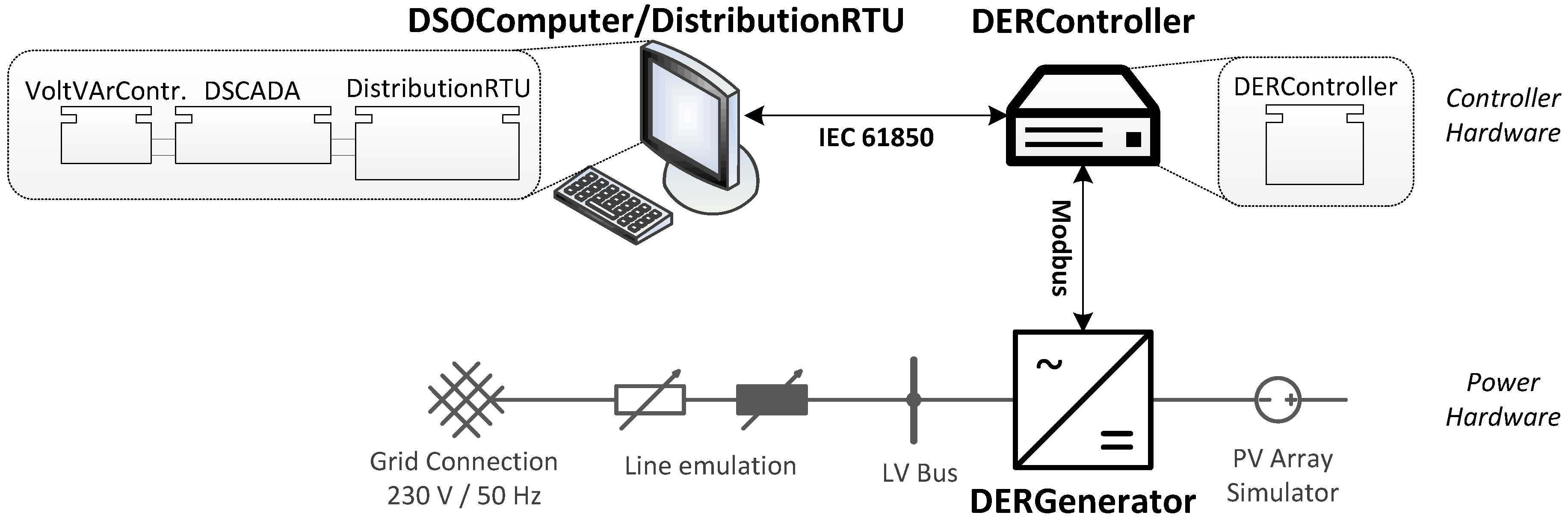
6.2.1. Laboratory Implementation

The laboratory setup is illustrated in Figure 13. In order to reduce the number of hardware components, only two controller devices were used: one for the DERController Device499 and one for both the DSOComputer and the DistributionRTU Devices499. Since only two Devices499 are available, the mapping of the SubApps499 must change. The VoltVArController, the DSCADA, and the DistributionRTU SubApps499 were mapped to the DSOComputer/DistributionRTU Device499 and the DERController SubApp499 was mapped to the DERController Device499.
As controller hardware a normal laptop with Windows 7 was used for the DSOComputer/ DistributionRTU and a Raspberry Pi 1 Model B+ with Raspbian was used for the DERController. The DERGenerator is a commercial off-the-shelf PV inverter connected on the DC side to a PV array simulator and on the AC side to the normal Low Voltage (LV) grid. To create a dependency between the voltage and the output of the inverter, a line impedance was emulated by the laboratory equipment.
The inverter has a Modbus TCP/IP control and measurement interface, but it does not have an IEC 61850 interface. To remedy this, a previously developed simple IEC 61850/Modbus gateway was used in the DERController [51]. The gateway translates all messages between Modbus and IEC 61850. For example, measurements from the inverter (e.g., voltage, power, reactive power) are translated into IEC 61850 measurements before they are sent to the DSOComputer/DistributionRTU.

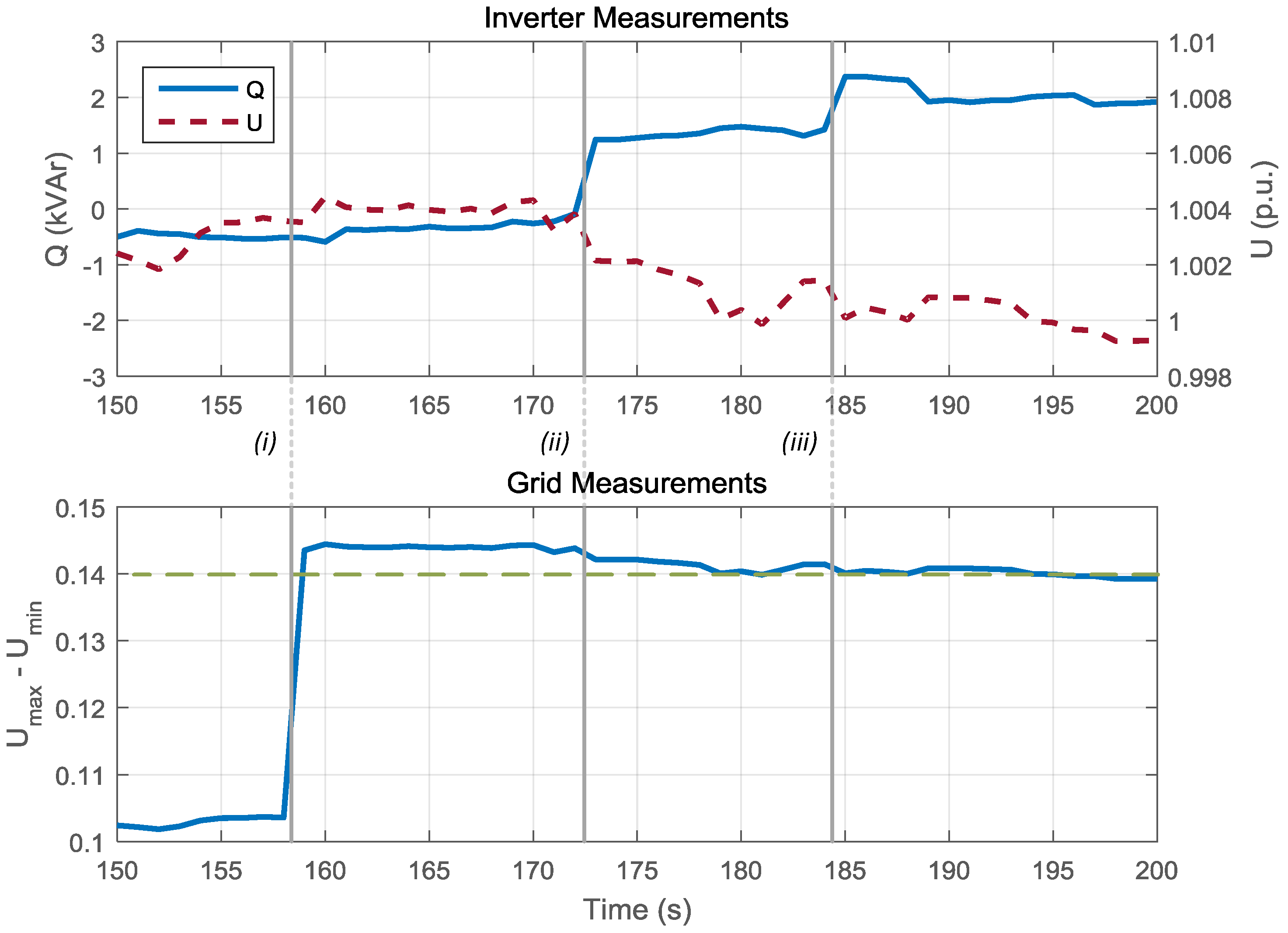
6.2.2. Performed Tests and Results

There are three main parts of the validation. The first two parts are the generation and download of the communication configurations, and the download of the control functions. These parts are related to the deployment of the control application. The third part of the validation is to test the functionality of the VoltVArController SubApp499. The precondition for the test is that the inverter is connected and feeding power into the grid.
Once the SubApps499 from Figure 13 have been mapped, communication infrastructure can be generated for connections between SubApps499 of different Resources499. Generated are both communication FBs499 as well as communication configurations. For this test case, only the connections between SubApps499 in the DSOComputer/DistributionRTU and SubApps499 in the DERController need to handled. These connections are all based on <interface>s and thus client/server FBs499 are generated: a server FB499 in DERController and a client FB499 in the DSOComputer/DistributionRTU. Also, all the <interface>s are derived from IEC 61850 <interface>s, which results in generation of SCL files for the communication configuration. The resulting IEC 61850 configuration is seen in Figure 14. The IED850 is named DERController after the Device499, and the LNs850 are prefixed with the name of the Socket499 interfaces.
After the configurations have been downloaded the SubApps499 VoltVArController, DSCADA, and DistributionRTU are deployed to the DSOComputer/DistributionRTU Device499, and the SubApp499 DERController is deployed to the DERController Device499. This deployment is done using standard IEC 61499 methods and is a built-in feature of 4DIAC. Therefore, it is also not necessary to generate any new code from the IEC 61499 model. After a deployment is made, the control is automatically started, whereupon the SCL files are loaded, and the IEC 61850 communication is initialized. Upon startup, the DERController also connects to the Modbus server of the DERGenerator.
Once the deployment is finished, the VoltVArController algorithm can be validated. For this validation, the inverter was configured to an active power output of 18kW and a reactive power output of 0 kVAr. The voltage measured by the inverter was forwarded to the VoltVArController at the vDER data output of the gridStatus FB499 (see Figure 12). The other voltage measurements (i.e., vVRC, vCBC, and cEOLM) were all fixed to 0.9 per unit (p.u.) within the control application. After stabilization, this resulted in a vDER voltage of around 1.004 p.u., and no extra reactive power. This issue is shown in the beginning of the time series in the top graph of Figure 15, where Q is the reactive power of the inverter and U is the measured voltage by the inverter (i.e., vDER).
In order to trigger the VoltVArController algorithm, a voltage spread increase was emulated. This happens at the first event (i), as depicted in Figure 15 after 158 s. At this event, the fixed voltage of vVRC was changed from 0.9 p.u. to 0.86 p.u. This increases the voltage spread (U m a x − U m i n in the bottom graph of Figure 15) above the allowed threshold of 0.14. This is detected by the algorithm in the VoltVArController and new volt-VAr curve parameters are calculated by the ChangeDeadband FB499 in Figure 12. The new curve parameters are sent to the DERController and finally to the DERGenerator (i.e., the inverter). With the new volt-VAr parameters, the inverter starts producing reactive power. This is shown as event (ii) in Figure 15. However, since the voltage spread is still too high, the volt-VAr parameters are changed by the VoltVArController once again after 185 s, event (iii) in Figure 15.
The results from the lab validation show that also requirement ER9 is realized by the rapid engineering method. The final requirement ER10 cannot be shown in this paper since no field tests were possible. Nevertheless, using the rapid engineering methodology together with the tools provided by IEC 61499 for deployment it should also be feasible to realize requirement ER10.

7. Reflection

The main goal of this paper is to show that it is possible to create an automated rapid engineering method that covers the whole development chain for smart grid automation applications—from use case design to its platform-specific implementation. To tackle this, a methodology is developed and described in this work. The implementation described in Section 6.1 also shows that a toolkit supporting this methodology can be created.
From the description of the rapid engineering methodology in Section 3.2 the function and code generation as well as the deployment phases have a high impact on the engineering effort and cost. By automating these two phases the time consuming work of translating the use case into executable code can be drastically decreased. The example use case in Section 5 and the validation in Section 6.2 also confirm this. In total the complete development process is reduced to the following steps:
  • Initial specification of the Application and the System using PSAL
  • Detailed specification of <interface>s and <event>s using protocol mappings
  • Transformation into an IEC 61499 Application499 and System499 model
  • Function design by implementation of SubAppTypes499
  • Generating and downloading the communication configurations (e.g., SCL files)
  • Downloading the Resources499 to their Devices499
From these steps only steps 1., 2., and 4. require significant inputs from the engineer. The other steps are fully automated and only require a simple activation by the user. The results in Figure 15 also show that these steps are enough to execute the validation test case from Section 6.2.
This can be compared to other solutions. Using a traditional development method, the use case would only be used as a specification, and based on this a new implementation would be created. Consequently, much of the work is done at least two times. A further disadvantage is that any changes in the use case description require manual changes in the implementation. Another solution only based on IEC 61499 would provide steps 4 and 5. However, it would not support the automatic generation of communication configurations and it would also miss the context with SGAM.
A final comparison can also be made with the SGAM Toolbox presented by Dänekas et al. [17]. Here, the context with SGAM is very much given, and through its integration into Enterprise Architect code generation is also supported. However, this code is generic, not specialized for smart grid applications, and there is no rapid deployment process. Furthermore, the generation of communication configurations is not supported by the SGAM Toolbox. It is also not possible to use generic communication patterns as provided by IEC 61499 (see Section 4.3 and Section 6.1). Therefore, they again have to be implemented manually and integrated into the source code.

8. Conclusions

With the smart grid rollout new intelligent concepts for measurement, control, and automation are being implemented in the power systems today. But, as seen in current research projects, the focus of these concepts is moving from a single system to a system of systems perspective. As a result, the engineering complexity will increase, followed by increased costs. In this spirit, there is also a need for smart and automated engineering methods. This paper tackles this need with a rapid engineering methodology for smart grid applications. It covers the complete development process from use case design to implementation and deployment in three main parts:
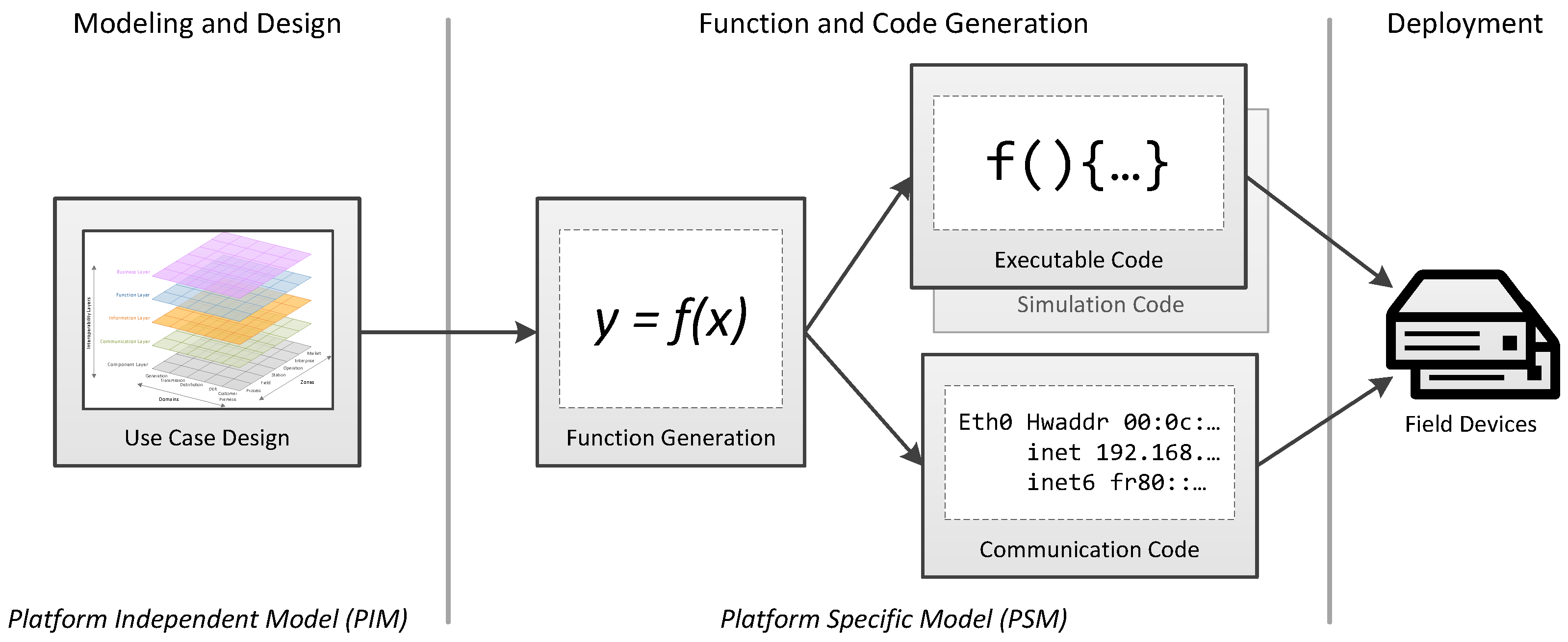
  • Modeling and design of the use case according to SGAM and a conceptual function design
  • Function and code generation of executable code as well as communication configurations
  • Deployment of the generated code to field devices
An MDE approach was used and for the first part PSAL was created, a DSL that supports use case design according to SGAM. PSAL has been combined with IEC 61499 in order to support detailed function implementations. Based on the descriptions from this part, two types of code are generated: executable code and communication configurations. One type of communication configurations that is supported is the generation of IEC 61850 SCL files. The last part is a deployment phase where the generated code is downloaded and executed on compatible field devices. This rapid engineering methodology is conceptualized and a prototypical implementation is developed and validated in a laboratory experiment.
This developed rapid engineering methodology can be compared to other solutions. With a traditional engineering methodology, the use case would only be used as a specification, and based on this, a new implementation is created. Consequently, much of the work is done at least two times, and changes in the use case description require manual changes in the implementation.
Compared with similar solutions like the SGAM Toolbox, presented by Dänekas et al. [17], some important differences can be pointed out. Although code generation is also supported by the SGAM Toolbox, this code is generic and not specialized for smart grid applications and there is no rapid deployment process. Another important advantage of the method in this paper is the generation of communication configurations, which is currently not supported by the SGAM Toolbox.
The future work will have to prove the feasibility of the rapid engineering methodology for large-scale applications. There are also a number of smaller improvements necessary which should be investigated: automatic generation of functions, generation of simulation code, or the integration of additional communication protocols. Another potential work will be to ensure a compatibility with the SGAM Toolbox by providing import/export services between the two tools. It is also a goal to provide the implemented rapid engineering methodology as an open-source toolkit.

Acknowledgments

This work is partly supported by the Austrian Ministry for Transport, Innovation and Technology (bmvit) and the Austrian Research Promotion Agency (FFG) under the “ICT of the Future Programme” in the OpenNES project (FFG No. 845632) as well as by the European Community’s Horizon 2020 Program (H2020/2014-2020) under project “ERIGrid” (Grant Agreement No. 654113).

Author Contributions

All three authors, Filip Pröstl Andrén, Thomas I. Strasser, and Wolfgang Kastner, contributed to the main concept and methodology. Filip Pröstl Andrén designed and executed the experimental validation, and he wrote the main parts of the manuscript. Thomas I. Strasser and Wolfgang Kastner proofread the paper.

Conflicts of Interest

The authors declare no conflict of interest.

Appendix A

The grammar of PSAL using an EBNF notation [38].
 1 PSAL ::= PsalContent*
 2 PsalContent ::= System | Application
 3 
 4 /* System grammar */
 5 System ::= 'system' ID '{' SystemContent* '}'
 6 SystemContent ::= Component | Connection
 7 Component ::= ICTComponent | ElectricalComponent
 8 ICTComponent ::= Device | OtherICTComponent
 9 Device ::= 'device' ID '{' DeviceContent* '}'
10 DeviceContent ::= Resource | PhysicalInterface
11 Resource ::= 'resource' ID
12 PhysicalInterface ::= PowerInterface | ICTInterface
13 PowerInterface ::= 'power' ID ('{' IDValuePair* '}')?
14 ICTInterface ::= ICTInterfaceType ID ('{' IDValuePair* '}')?
15 ICTInterfaceType ::= 'ethernet' | 'wireless' | 'serial' | 'analogue' | 'digital'
16 IDValuePair ::= ID '=' ValueLiteral
17 OtherICTComponent ::= OtherICTComponentTypes ID ('{' IDValuePair* '}')?
18 OtherICTComponentTypes ::= 'gateway' | 'switch' | 'router'
19 ElectricalComponent ::= ElectricalComponentType ID '{' ElectricalComponentContent* '}'
20 ElectricalComponentType ::= 'transformer' | 'DER' | 'line' | 'breaker' | 'load' | 'busbar' | 'slack'
21 ElectricalComponentContent ::= PhysicalInterface | IDValuePair
22 Connection ::= 'connect' QualifiedName 'with' QualifiedName ('{' IDValuePair* '}')?
23 
24 /* Application grammar */
25 Application ::= 'application' ID '{' ApplicationContent* '}'
26 ApplicationContent ::= Function | Connection | <module>
27 Function :: = 'function' ID (FunctionMapping)? '{' FunctionContent* '}'
28 FunctionMapping ::= 'at' QualifiedName
29 FunctionContent ::= Function | Connection | ServiceImplementation
30 ServiceImplementation ::= ProvidedService | RequestedService
31 ProvidedService ::= ProvidedIDLInterface | ProvidedIDLEvent
32 RequestedService ::= RequestedIDLInterface | RequestedIDLEvent
33 ProvidedIDLInterface ::= 'provides' QualifiedName ID ('{' ParameterAssignment* '}')?
34 ParameterAssignment ::= QualifiedName '=' ValueLiteral
35 RequestedIDLInterface ::= 'requests' QualifiedName ID ('{' ParameterAssignment* '}')?
36 ProvidedIDLEvent ::= 'emits' QualifiedName ID ('{' ParameterAssignment* '}')?
37 RequestedIDLEvent ::= 'consumes' QualifiedName ID ('{' ParameterAssignment* '}')?
38 
39 /* Information grammar
40  * Based on the OMG IDL specification [39] , where all elements in brackets
41  * are copied from the specification. Some small changes were made:
42  *  - All semicolons were removed.
43  *  - All references to grammar elements without brackets show changes. These changes
44  * also indicates how the OMG IDL was integrated.
45  * Elements in brackets that are not explicitly defined here can be found in [39].
46  */
47 CommunicationParameter ::= 'parameter' ID ('=' ValueLiteral)?
48 <definition> ::= <type_dcl> | <const_dcl> | <except_dcl> | <interface>
49                | <module>  | <value>  | <type_id_dcl>  | <type_prefix_dcl> 
50                | <event>  | <component>  | <home_dcl> | CommunicationParameter
51 <module> ::= 'module' ID '{' <definition>+ '}'
52 <interface> ::= <interface_dcl> | <forward_dcl>
53 <interface_dcl> ::= <interface_header> '{' <interface_body> '}'
54 <interface_header> ::= ('abstract' | 'local')? 'interface' ID (<interface_inheritance_spec>)?
55 <interface_body> ::= <export>*
56 <export> ::= <type_dcl>  | <const_dcl>  | <except_dcl>  | <attr_dcl> 
57      | <op_dcl>  | <type_id_dcl>  | <type_prefix_dcl> | CommunicationParameter
58 <interface_inheritance_spec> ::= ':' <interface_name> (',' <interface_name>)*
59 <attr_dcl> ::= <readonly_attr_spec> | <attr_spec>
60 <readonly_attr_spec> ::= 'readonly' 'attribute' TypeSpecification <readonly_attr_declarator>
61 <readonly_attr_declarator> ::= ID <raises_expr> | ID (',' ID)*
62 <attr_spec> ::= 'attribute' TypeSpecification <attr_declarator>
63 <attr_declarator> ::= ID <attr_raises_expr> | ID (',' ID)*
64 <op_dcl> ::= <op_attribute>? <op_type_spec> ID <parameter_dcls> <raises_expr>? <context_expr>?
65 <op_attribute> ::= 'oneway'
66 <op_type_spec> ::= TypeSpecification | 'void'
67 <parameter_dcls> ::= '(' <param_dcl> (',' <param_dcl>)* ')' | '(' ')'
68 <param_dcl> ::= <param_attribute> TypeSpecification ID
69 <param_attribute> ::= 'in' | 'out' | 'inout'
70 <event> ::= <event_dcl> | <event_abs_dcl> | <event_forward_dcl>
71 <event_dcl> ::= <event_header> '{' <value_element>* '}'
72 <event_header> ::= ('custom')? 'eventtype' ID <value_inheritance_spec>?
73 <value_element> ::= <export> | < state_member> | <init_dcl>
74 <state_member> ::=('public' | 'private') TypeSpecification <declarators>
75 <declarators> ::= <declarator> (',' <declarator>)*
76 <declarator> ::= ID | <array_declarator>
77 <type_dcl> ::= 'typedef' <type_declarator> | <struct_type> | <union_type> | <enum_type>
78      | 'native' ID | <constr_forward_decl>
79 <enum_type> ::= 'enum' ID '{' <enumerator> (',' <enumerator>)* '}'
80 <enumerator> ::= ID
81 TypeSpecification ::= Types | QualifiedName
82
83 /* Terminals and literals */
84 ID ::= ([a-zA-Z] | '_') ([a-zA-Z0-9] | '_')*
85 String ::= '"' [^"]* '"'
86 QualifiedName ::= ID ('.' ID)*
87 ValueLiteral ::= String | BooleanLiteral | NumberLiteral
88 BooleanLiteral ::= 'true' | 'false'
89 NumberLiteral ::= ('-')? (Int | FloatingPtLiteral | HexLiteral)
90 Int ::= [0-9]+
91 FloatingPtLiteral ::= INT '.' INT | INT | '.' INT
92 HexLiteral ::= '0' 'x' [0-9a-fA-F]+
93 Annotation ::= '@' ID AnnotationParams?
94 AnnotationParams ::= '(' AnnotationParam (',' AnnotationParam)* ')' | '(' ')'
95 AnnotationParam ::= ID
96 Types ::= 'boolean' | 'float32' | 'float64' | 'int8' | 'int16' | 'int32' | 'int64' | 'uint8'
97      | 'uint16' | 'uint32' | 'uint64'| 'byte' | 'word16' | 'word32' | 'word64'
98      | 'string'| 'date'

References

  1. International Energy Agency. World Energy Outlook 2013; Technical Report; International Energy Agency: Paris, France, 2013. [Google Scholar]
  2. Liserre, M.; Sauter, T.; Hung, J. Future Energy Systems: Integrating Renewable Energy Sources into the Smart Power Grid Through Industrial Electronics. IEEE Ind. Electron. Mag. 2010, 4, 18–37. [Google Scholar] [CrossRef]
  3. Palensky, P.; Dietrich, D. Demand Side Management: Demand Response, Intelligent Energy Systems, and Smart Loads. IEEE Trans. Ind. Inform. 2011, 7, 381–388. [Google Scholar] [CrossRef]
  4. Gungor, V.; Sahin, D.; Kocak, T.; Ergut, S.; Buccella, C.; Cecati, C.; Hancke, G. Smart Grid Technologies: Communication Technologies and Standards. IEEE Trans. Ind. Inform. 2011, 7, 529–539. [Google Scholar] [CrossRef]
  5. Ardito, L.; Procaccianti, G.; Menga, G.; Morisio, M. Smart Grid Technologies in Europe: An Overview. Energies 2013, 6, 251–281. [Google Scholar] [CrossRef]
  6. Santodomingo, R.; Uslar, M.; Göring, A.; Gottschalk, M.; Nordström, L.; Saleem, A.; Chenine, M. SGAM-based methodology to analyse Smart Grid solutions in DISCERN European research project. In Proceedings of the 2014 IEEE International Energy Conference (ENERGYCON), Cavtat, Croatia, 13–16 May 2014; pp. 751–758.
  7. Frascella, A.; Swiderski, J.; Proserpio, G.; Rikos, E.; Temiz, A.; Babs, A.; Uslar, M.; Branchetti, S.; Graditi, G. Looking for the unified classification and evaluation approach of SG interface standards for the purposes of ELECTRA IRP. In Proceedings of the International Symposium on Smart Electric Distribution Systems and Technologies (EDST), Vienna, Austria, 8–11 September 2015.
  8. CEN-CENELEC-ETSI Smart Grid Coordination Group. Reference Architecture for the Smart Grid; Technical Report; CEN-CENELEC-ETSI Smart Grid Coordination Group: Brussels, Belgium, 2012. [Google Scholar]
  9. International Electrotechnical Commission. IEC 62559: Use Case Methodology; International Electrotechnical Commission: Geneva, Switzerland, 2015. [Google Scholar]
  10. Andrén, F.; Strasser, T.; Rohjans, S.; Uslar, M. Analyzing the need for a common modeling language for Smart Grid applications. In Proceedings of the 11th IEEE International Conference on Industrial Informatics (INDIN), Bochum, Germany, 29–31 July 2013.
  11. Mellor, S.J.; Kendall, S.; Uhl, A.; Weise, D. MDA Distilled; Addison Wesley Longman Publishing Co., Inc.: Redwood City, CA, USA, 2004. [Google Scholar]
  12. Siegel, J. Developing in OMG’s New Model-Driven Architecture; Technical Report; Object Management Group (OMG): Needham, MA, USA, 2001. [Google Scholar]
  13. Strasser, T.; Pröstl Andrén, F.; Lauss, G.; Bründlinger, R.; Brunner, H.; Moyo, C.; Seitl, C.; Rohjans, S.; Lehnhoff, S.; Palensky, P.; et al. Towards holistic power distribution system validation and testing—An overview and discussion of different possibilities. E I Elektrotech. Informationstech. 2016, 134, 71–77. [Google Scholar] [CrossRef]
  14. European Commission (EC). M/490 Standardization Mandate to European Standardisation Organisations (ESOs) to Support European Smart Grid Deployment; Technical Report; European Commission (EC): Brussels, Belgium, 2012. [Google Scholar]
  15. CEN-CENELEC-ETSI Smart Grid Coordination Group. SG-CG/M490/F Overview of SG-CG Methodologies; Technical Report; CEN-CENELEC-ETSI Smart Grid Coordination Group: Brussels, Belgium, 2014. [Google Scholar]
  16. CEN-CENELEC-ETSI Smart Grid Coordination Group. Use Case Collection, Management, Repository, Analysis and Harmonization; Technical Report; CEN-CENELEC-ETSI Smart Grid Coordination Group: Brussels, Belgium, 2012. [Google Scholar]
  17. Dänekas, C.; Neureiter, C.; Rohjans, S.; Uslar, M.; Engel, D. Towards a Model-Driven-Architecture Process for Smart Grid Projects. In Digital Enterprise Design & Management; Advances in Intelligent Systems and Computing; Benghozi, P.J., Krob, D., Lonjon, A., Panetto, H., Eds.; Springer: Cham, Switzerland, 2014; Volume 261, pp. 47–58. [Google Scholar]
  18. International Electrotechnical Commission. IEC 61499: Function Blocks; International Electrotechnical Commission (IEC): Geneva, Switzerland, 2012. [Google Scholar]
  19. International Electrotechnical Commission. IEC 61131-3: Programmable Controllers—Part 3: Programming Languages; International Electrotechnical Commission (IEC): Geneva, Switzerland, 2012. [Google Scholar]
  20. Lewis, R.W. Modeling Control Systems Using IEC 61499; The Institution of Engineering and Technology: Stevenage, UK, 2001. [Google Scholar]
  21. International Electrotechnical Commission. IEC 61850: Communication Networks and Systems for Power Utility Automation; International Electrotechnical Commission (IEC): Geneva, Switzerland, 2010. [Google Scholar]
  22. Colak, I.; Sagiroglu, S.; Fulli, G.; Yesilbudak, M.; Covrig, C.F. A survey on the critical issues in smart grid technologies. Renew. Sustain. Energy Rev. 2016, 54, 396–405. [Google Scholar] [CrossRef]
  23. Kurtev, I. State of the art of QVT: A model transformation language standard. In Applications of Graph Transformations with Industrial Relevance; Springer: Cham, Switzerland, 2008; pp. 377–393. [Google Scholar]
  24. Fowler, M. Domain-Specific Languages; Pearson Education: London, UK, 2010. [Google Scholar]
  25. Parr, T. The Definitive ANTLR Reference: Building Domain-Specific Languages; Pragmatic Bookshelf: Raleigh, NC, USA, 2007. [Google Scholar]
  26. Petre, M. Why Looking Isn’t Always Seeing: Readership Skills and Graphical Programming. Commun. ACM 1995, 38, 33–44. [Google Scholar] [CrossRef]
  27. Shin, I.J.; Song, B.K.; Eom, D.S. Auto-Mapping and Configuration Method of IEC 61850 Information Model Based on OPC UA. Energies 2016, 9, 901. [Google Scholar] [CrossRef]
  28. International Electrotechnical Commission. IEC 61970: Energy Management System Application Program Interface (EMS-API); International Electrotechnical Commission (IEC): Geneva, Switzerland, 2004. [Google Scholar]
  29. Lefrançois, M.; Habault, G.; Ramondou, C.; Françon, E. Outsourcing Electric Vehicle Smart Charging on the Web of Data. In Proceedings of the First International Conference on Green Communications, Computing and Technologies, (GREEN 2016), Nice, France, 24–28 July 2016.
  30. Broy, M. Model-driven architecture-centric engineering of (embedded) software intensive systems: Modeling theories and architectural milestones. Innov. Syst. Softw. Eng. 2007, 3, 75–102. [Google Scholar] [CrossRef]
  31. Paulo, R.; Carvalho, A. Towards model-driven design of substation automation systems. In Proceedings of the 2005 18th International Conference and Exhibition on Electricity Distribution, (CIRED 2005), Lyon, France, 6–9 June 2005.
  32. Yang, C.W.; Vyatkin, V.; Mousavi, A.; Dubinin, V. On automatic generation of IEC61850/IEC61499 substation automation systems enabled by ontology. In Proceedings of the 40th Annual Conference of the IEEE Industrial Electronics Society (IECON), Dallas, TX, USA, 29 October–1 November 2014.
  33. Blair, S.M.; Coffele, F.; Booth, C.D.; Burt, G.M. An Open Platform for Rapid-Prototyping Protection and Control Schemes With IEC 61850. IEEE Trans. Power Deliv. 2013, 28, 1103–1110. [Google Scholar] [CrossRef] [Green Version]
  34. Andrén, F.; Stifter, M.; Strasser, T. Towards a Semantic Driven Framework for Smart Grid Applications: Model-Driven Development using CIM, IEC 61850 and IEC 61499. Informatik-Spektrum 2013, 36, 58–68. [Google Scholar] [CrossRef]
  35. Pröstl Andrén, F.; Strasser, T.; Kastner, W. Applying the SGAM Methodology for Rapid Prototyping of Smart Grid Applications. In Proceedings of the 42nd Annual Conference of the IEEE Industrial Electronics Society (IECON), Florence, Italy, 24–27 October 2016.
  36. Pröstl Andrén, F.; Strasser, T.; Langthaler, O.; Veichtlbauer, A.; Kasberger, C.; Felbauer, G. Open and Interoperable ICT Solution for Integrating Distributed Energy Resources into Smart Grids. In Proceedings of the 21th IEEE International Conference on Emerging Technologies and Factory Automation (ETFA’2016), Berlin, Germany, 6–9 September 2016.
  37. Schwalbe, R.; Einfalt, A.; Abart, A.; Radauer, M.; Brunner, H. DG DemoNet Smart LV Grid—Robust Control Architecture to Increase DG Hosting Capacity. In Proceedings of the 23rd International Conference and Exhibition on Electricity Distribution, CIRED 2015, Lyon, France, 6–18 June 2015.
  38. World Wide Web Consortium (W3C). EBNF for XML; World Wide Web Consortium (W3C): Cambridge, MA, USA, 2004. [Google Scholar]
  39. Object Management Group. Interface Definition Language Version 3.5; Technical Report; Object Management Group (OMG): Needham, MA, USA, 2014. [Google Scholar]
  40. Slee, M.; Agarwal, A.; Kwiatkowski, M. Thrift: Scalable Cross-Language Services Implementation; Technical Report; Facebook: California, CA, USA, 2007. [Google Scholar]
  41. Vyatkin, V.; Zhabelova, G.; Higgins, N.; Ulieru, M.; Schwarz, K.; Nair, N. Standards-enabled Smart Grid for the future Energy Web. In Proceedings of the Innovative Smart Grid Technologies (ISGT), Gaithersburg, MD, USA, 19–21 January 2010; pp. 1–9.
  42. Strasser, T.; Andrén, F.; Vyatkin, V.; Zhabelova, G.; Yang, C.W. Towards an IEC 61499 compliance profile for smart grids review and analysis of possibilities. In Proceedings of the 38th Annual Conference on IEEE Industrial Electronics Society (IECON), Montreal, QC, Canada, 25–28 October 2012; pp. 3750–3757.
  43. Andrén, F.; Bründlinger, R.; Strasser, T. IEC 61850/61499 Control of Distributed Energy Resources: Concept, Guidelines, and Implementation. IEEE Trans. Energy Convers. 2014, 29, 1008–1017. [Google Scholar] [CrossRef]
  44. Andren, F.; Strasser, T.; Kastner, W. Model-driven engineering applied to Smart Grid automation using IEC 61850 and IEC 61499. In Proceedings of the Power Systems Computation Conference (PSCC), Wroclaw, Poland, 18–22 August 2014; pp. 1–7.
  45. Hegny, I.; Strasser, T.; Melik-Merkumians, M.; Wenger, M.; Zoitl, A. Towards an increased reusability of distributed control applications modeled in IEC 61499. In Proceedings of the 2012 IEEE International Conference on Emerging Technologies and Factory Automation (ETFA), Krakow, Poland, 17–21 September 2012.
  46. Green, B.D. Integrated Volt VAR Control Centralized; Technical Report; American Electric Power: Columbus, OH, USA, 2011. [Google Scholar]
  47. International Electrotechnical Commission. IEC/TR 61850-90-7—Communication Networks and Systems for Power Utility Automation—Part 90-7: Object Models for Power Converters in Distributed Energy Resources (DER) Systems; International Electrotechnical Commission (IEC): Geneva, Switzerland, 2013. [Google Scholar]
  48. Efftinge, S.; Völter, M. oAW xText: A framework for textual DSLs. In Proceedings of the Workshop on Modeling Symposium at Eclipse Summit, Esslingen, Germany, 11–12 October 2006; Volume 32.
  49. Zoitl, A.; Strasser, T.; Valentini, A. Open source initiatives as basis for the establishment of new technologies in industrial automation: 4DIAC a case study. In Proceedings of the 2010 IEEE International Symposium on Industrial Electronics (ISIE), Bari, Italy, 4–7 Juli 2010.
  50. Lednicki, L.; Carlson, J. A framework for generation of inter-node communication in component-based distributed embedded systems. In Proceedings of the 2014 IEEE Emerging Technology and Factory Automation (ETFA), Barcelona, Spain, 16–19 September 2014; pp. 1–8.
  51. Strasser, T.; Andrén, F.; Bründlinger, R.; Garabandic, D. Integrating PV into the Smart Grid—Implementation of an IEC 61850 Interface for Large Scale PV Inverters. In Proceedings of the 28th European Photovoltaic Solar Energy Conference and Exhibition (EUPVSEC), Paris, France, 30 September–4 October 2013.
Figure 1. Overview of the Smart Grid Architecture Model (SGAM), based on [14].
Energies 10 00374 g001
Figure 2. IEC 61499 reference models for distributed automation, based on [18,20].
Energies 10 00374 g002
Figure 3. Main modeling objects as defined in IEC 61850-6, based on [21].
Energies 10 00374 g003
Figure 4. Conceptual view of the proposed rapid engineering methodology.
Energies 10 00374 g004
Figure 5. Simplified Unified Modeling Language (UML) representation of Power System Automation Language (PSAL)’s domain model, on top of the SGAM structure.
Energies 10 00374 g005
Figure 6. Mapping between IEC 61499 and PSAL for the component model.
Energies 10 00374 g006
Figure 7. Illustrating example of a mapping between an <interface> and an Adapter499: (a<interface> definition in PSAL; (b) Adapter499 type definition in IEC 61499.
Energies 10 00374 g007
Figure 8. Illustrating example of a mapping between an <event> and an Adapter499: (a) <event> definition in PSAL; (b) Adapter499 type definition in IEC 61499.
Energies 10 00374 g008
Figure 9. Mapping between an LN850 and an <interface>: (a) Excerpt of the LN850 MMXU in IEC 61850; (b) MMXU as SCL description; (c) MMXU as <interface> description.
Energies 10 00374 g009
Figure 10. Overview of the example use case Integrated Volt VAr Control Centralized [46].
Energies 10 00374 g010
Figure 11. VoltVArControlCentralized as IEC 61499 Application499.
Energies 10 00374 g011
Figure 12. Implementation of the VoltVArController SubApp499 from Figure 11.
Energies 10 00374 g012
Figure 13. Laboratory setup for the use case validation.
Energies 10 00374 g013
Figure 14. Generated System Configuration Language (SCL) file for configuration of the IEC 61850 server in DERController.
Energies 10 00374 g014
Figure 15. Measurements from the laboratory validation with three main events: (i) detection of voltage band violation, (ii) first curve correction, and (iii) second curve correction.
Energies 10 00374 g015
Table 1. Actors and stakeholders involved in the rapid engineering methodology.
#Actor Name and Description
A1Utility Operator
The operator of the power grid and its corresponding assets. A common activity for the utility operator is the specification of a certain use case or functionality before implementation. The utility operator may also be directly involved in the implementation and validation of applications.
A2System Integrator
The system integrator delivers and integrates a whole or part of a system (e.g., a substation) to a utility operator. Commonly the utility operator specifies an application that is implemented by one or more system integrators.
A3Manufacturer/Device Vendor
The manufacturer of grid components. This actor must have the possibility to implement functionality on all levels of a component (i.e., low-level as well as high-level functionality).
A4Third-Party Service Provider
The third-party service provider may be interested in implementing services for smart grid components (e.g., implementing direct-marketing services for smart inverters).
A5Plant Operator
The operator of a power plant or a flexible load (e.g., a building or an energy storage unit). This could, for example, be a virtual power plant operator who needs to optimize the usage of the involved plants. It may also be an aggregator for ancillary services or flexibility.
A6Plant Owner
The owner of a power plant or a flexible load. This may in many cases be the same actor as the plant operator. The owner may want to install certain monitoring functionality, or connect the plant to a building automation system.
Table 2. Engineering requirements for the rapid engineering process.
#Requirement Name and Description
ER1Business Case Specification
Usually as the first step, before any other specifications are made, it must be clear what the benefit and drawbacks are for the involved actor. This is the definition of business cases and their related goals.
ER2Functional Specification
From the business cases, one or more functions are derived. For each distinct function, its inputs, outputs, and goals are specified. This work focuses on automation functions (e.g., control, monitoring, supervisory control).
ER3Functional Implementation
The specified functions that are owned by the business actor need to be implemented using a formal software specification (e.g., UML, IEC 61499).
ER4System Specification
The system specification specifies the architecture of the execution hardware and the system upon it will operate. This includes power system equipment, ICT equipment, and field devices. It should be possible to model already existing as well as new smart grid system infrastructure.
ER5Function-System Mapping
In order to know where a function should be executed it must be mapped to an execution platform. This is done with a function-system mapping where one or more functions are assigned to a specific hardware platform.
ER6Information Model Specification
Data that is exchanged between functions must be assigned to an information model, with the purpose to define semantics for the data. It must also be possible to use existing information models (e.g., IEC 61850, SunSpec).
ER7Communication Specification
Although an information model is already defined for a certain exchange, it should also be possible to define what kind of protocol is used for the communication. This must also be possible on different OSI (Open Systems Interconnection) layers.
ER8Application Implementation
After specification, the use case must be implemented for the specified system (see ER4). This means that functions are ported to their host platform and all communication interfaces must be properly configured.
ER9Validation and Testing
With the validation, the functionality of the system is tested before it is deployed. The validation can either be simulative and/or with real components (e.g., hardware-in-the-loop experiments, laboratory tests).
ER10Field Deployment
To operate the implemented application, it must first be deployed to the field. This includes installation of new hardware components, software functions, and configuration of the communication and ICT system.

