Article

Effects of Energy Storage Systems Grid Code Requirements on Interface Protection Performances in Low Voltage Networks

1
Department of Industrial Engineering, University of Padova, 35131 Padova, Italy
2
e-distribuzione Società per azioni (S.p.A.), Via Ombrone 2, 00198 Roma, Italy
*
Author to whom correspondence should be addressed.
Energies 2017, 10(3), 387; https://doi.org/10.3390/en10030387
Submission received: 14 February 2017 / Revised: 8 March 2017 / Accepted: 15 March 2017 / Published: 18 March 2017

Abstract

:
The ever-growing penetration of local generation in distribution networks and the large diffusion of energy storage systems (ESSs) foreseen in the near future are bound to affect the effectiveness of interface protection systems (IPSs), with negative impact on the safety of medium voltage (MV) and low voltage (LV) systems. With the scope of preserving the main network stability, international and national grid connection codes have been updated recently. Consequently, distributed generators (DGs) and storage units are increasingly called to provide stabilizing functions according to local voltage and frequency. This can be achieved by suitably controlling the electronic power converters interfacing small-scale generators and storage units to the network. The paper focuses on the regulating functions required to storage units by grid codes currently in force in the European area. Indeed, even if such regulating actions would enable local units in participating to network stability under normal steady-state operating conditions, it is shown through dynamic simulations that they may increase the risk of unintentional islanding occurrence. This means that dangerous operating conditions may arise in LV networks in case dispersed generators and storage systems are present, even if all the end-users are compliant with currently applied connection standards.

1. Introduction

The ongoing exploitation of generating units based on renewable energy sources (RESs) embedded in the power distribution system (distributed generation (DG)) is continuously modifying the way such networks are managed by distribution system operators (DSOs). The largest part of RES based generators connected to medium voltage (MV) and low voltage (LV) grids (e.g., photovoltaic (PV), direct-drive wind turbines (WTs), hydroelectric power plants operating at variable rotating speed, etc.) are commonly interfaced with the electrical system through static power converters. Consequently, these generators do not intrinsically provide contributions to network stability, e.g., voltage and frequency regulation, as done by rotating generators.
Meanwhile, a large diffusion of energy storage systems (ESSs), mainly based on electrochemical batteries (BESSs), is expected to take place in the next future on both MV and LV networks. The ESSs exploitation at the end-user level, in coexistence with DGs, is encouraged by a variety of different advantages and opportunities [1,2,3], such as:
  • The forecasted decreasing cost of storage systems, as a consequence of its near future diffusion involving increased production capacity;
  • Economic advantages for active end-users, enabling the optimal self-consumption of locally produced energy, alternatively to incentivizing mechanisms (e.g., net metering, expected to end soon, at least in Italy);
  • Leveling the DG power production, both in terms of daily peak shaving function, e.g., for PV generators, and in short times, to mitigate the perturbations of renewable sources as in the case of WTs;
  • Opportunities in the participation of end-users to ancillary services markets, even if they integrate partially unpredictable energy sources;
  • Contribution in supplying the load peak power, reducing the contractual value of admitted power absorption and consequently a consistent portion of the end-user bill (since network operation costs, evaluated on the rated power of the connection, are foreseen to increase in the coming years); and
  • Local supply of end-users in the case of distribution network outage.
As the largest part of RES based generators, ESSs are interfaced to the network through static electronic converters. An excessive and unplanned penetration of power electronic interfaced systems in distribution networks, partially replacing the traditional centralized generation making use of rotating machines, reduces the connected regulating energy available in the interconnected network and may consequently affect the network stability in terms of voltage and frequency [4]. In order to counteract this kind of problems, national and international authorities updated their standards and grid codes regarding the connection of active end-users to distribution networks, including both DGs and ESSs. For instance, the most recent versions of European standards report the recommendations for the connection of generating plants (rated current above 16 A), in particular CENELEC TS 50549-1 [5] for the LV and CENELEC TS 50549-2 [6] for the MV distribution networks, whereas CENELEC EN 50438 [7] regulates LV micro-generating plants with rated current under 16 A. Italian grid codes CEI 0-16 [8] and CEI 0-21 [9] derive proposals from [5,6,7] and indicate technical rules for the connection of passive and active end-users to the MV and LV networks, respectively. Both DG units and ESSs are required to contribute to the network stability, as described in the next sections. At the same time, in order to improve fault ride through capabilities, extended operating ranges have been introduced for voltage and frequency in the interface protection systems (IPSs) of local energy sources.
In the case of DGs, the new power regulation strategies have been demonstrated to support network stability during steady-state regimes and to contribute in intentional islanding management (e.g., planned disconnection from the main grid or islanded power systems) [10,11,12,13]. Nevertheless, dangerous conditions could be experienced by the distribution system during transients, potentially leading to unintentional islanding phenomena, due to the masking effect of stabilizing functions on IPSs, causing the anti-islanding protection failure [14,15,16,17,18,19,20].
In the ESSs case, several studies have been carried out demonstrating their fundamental contribution to microgrids stability. In particular, different management criteria and protection systems have been proposed to regulate both the grid-connected and the islanded states, furthermore investigating the controlled transition between the two scenarios [21,22,23,24,25].
Differently from these researches, this work studies in-depth the impact on distribution networks of grid-connected ESSs (i.e., responding to grid codes requirements nowadays in force), particularly in terms of possible unsafe operation such as the uncontrolled islanding of a network portion for a not negligible time duration. It should be noted that the regulating functions described below are specific grid connection standards, which requirements have been suitably modeled making use of a commercial simulation software for reproducing the behaviors the local units are required to perform in response to network parameters (i.e., frequency and voltage) variations at the connection node. Finally, the paper aims at verifying whether IPSs currently defined by present standards are adequate to identify unintentional islanding in the case storage units with stabilizing functions are connected to the LV distribution grid. Results are comparable with similar studies obtained according with Korean connection codes [26].
In the following, Section 2 recalls the requirements currently applied to DG units, in terms of both stabilizing functions and IPS characteristics, whereas Section 3 discusses the ESS stabilizing functions, considering AC interfaced storage units and ESS connected to the DC side of the generating unit converter. Study case main data are collected in Section 4, whereas Section 5 reports and critically analyses the results of dynamic simulations. Conclusions on the impact of ESS stabilizing function on loss-of-main protection effectiveness are drawn in Section 6 focusing on LV networks.

2. Present Italian Standard Requirements for DG

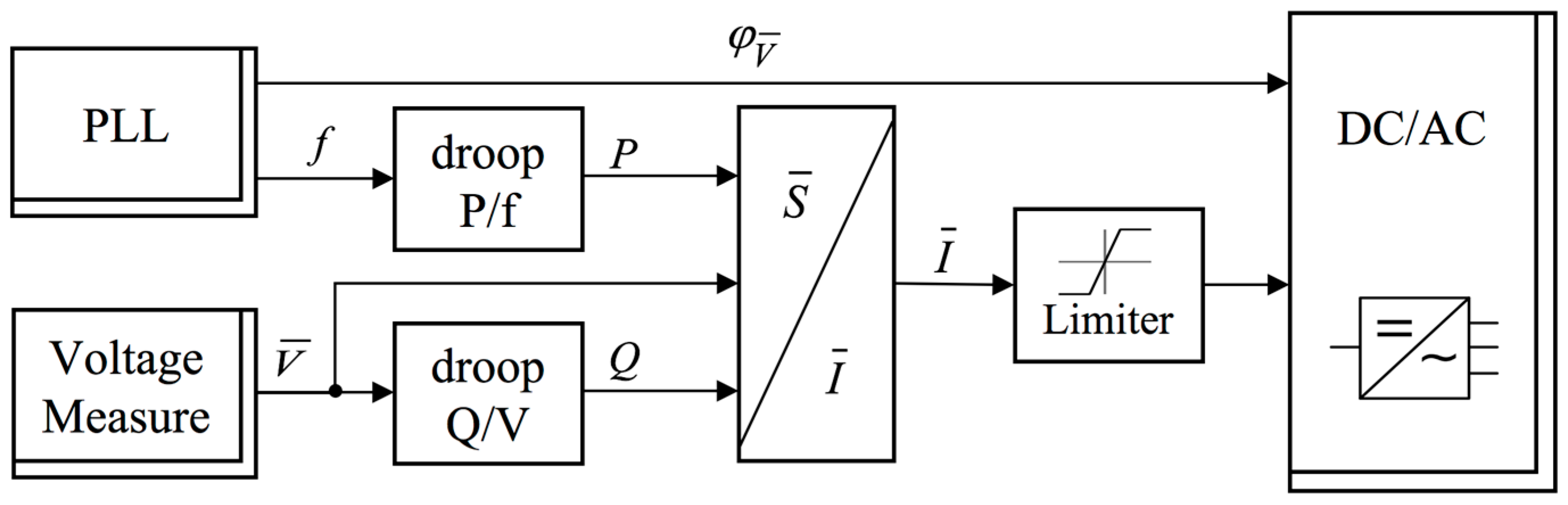
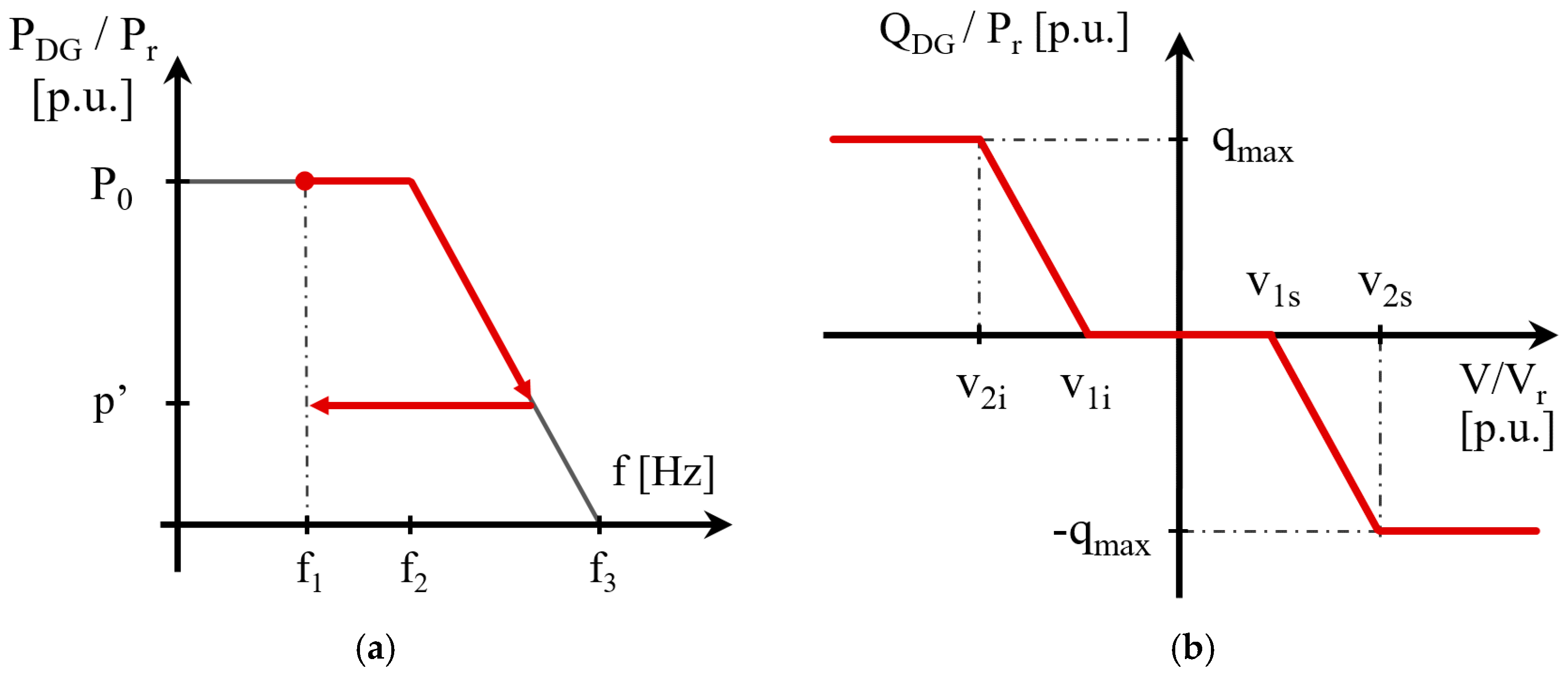
2.1. P/f and Q/V regulations

The Italian standard CEI 0-21 [9] specifies, among others, the requirements for the DGs’ contribution to network stability (ESSs are separately and hereinafter discussed). Depending on locally measured frequency f, DGs are required to participate to the frequency regulation by modulating the produced active power P in accordance with the droop curve reported in Figure 1a. In the case a severe over-frequency occurs (f > f2), the generator responds by reducing its active power production, with pre-set statism S0 = 2.4%, up to f3 (P = 0 if f > f3). The statism value is based on the actual production of the DG plant before the frequency perturbation (P0), not referring to the DG plant rated power Pr neither to the technical characteristics of the power converter. In the case the frequency time derivative turns negative, the power set-point has to be maintained constant at the reached value p’ for 300 s in order to achieve a sort of intentional hysteresis and to preserve the system stability. The local measured frequency f is the reference signal for the regulation, whereas values of the activation thresholds are reported in Table 1.
Meanwhile, the activation of the Q/V function, according to the characteristic curve in Figure 1b (right) described in the grid code, allows the DG to contribute in regulating the local voltage. The generation unit is asked to behave as an inductive or a capacitive load in the case of over-voltage or under-voltage, respectively (i.e., absorbing or injecting inductive reactive power). Otherwise, in the case the local measured voltage V is within an admitted range of variation, centered in the rated value (according to Table 1), the reactive power contribution is null. Only in the last versions of the CENELEC TS guidelines and of the Italian grid code [9] in force from July 2016 for new units, an intentional delay has been added to the Q/V regulation aiming at reducing the risk of unintentional islanding (nevertheless, generator and storage units connected to distribution networks before that date do not comply with this new requirement). Furthermore, it should be noted that LV end-users are increasing their operative power factor due to the large use of appliances faced by power electronic devices [27], the weight of the Q/V regulation in contributing to undesired islanding is limited if compared with the role of the P/f stabilizing function.
Finally, the DG is required to adopt a rectangular capability area: this means that the generation unit is called to supply its reactive power contribution to the network stability according to Pr, independently of the primary source availability. The Q/V regulation is required to operate in the case the DG active power increases above 0.2 p.u. and remains activated until the active power decreases below 0.05 p.u. The regulating function Q/V is not required if the DG rated power is smaller than 11.08 kW.
Although in LV networks, where lines R/X ratio is above 1, it has been demonstrated that a better stability control would be achieved through P/V and Q/f droops [28,29,30], the paper focuses on present standard requirements, so it investigates solely the stabilizing functions defined in present grid codes (P/f and Q/V) to verify the effectiveness of currently required protections in avoiding dangerous operating conditions, in particular the unintentional islanding.

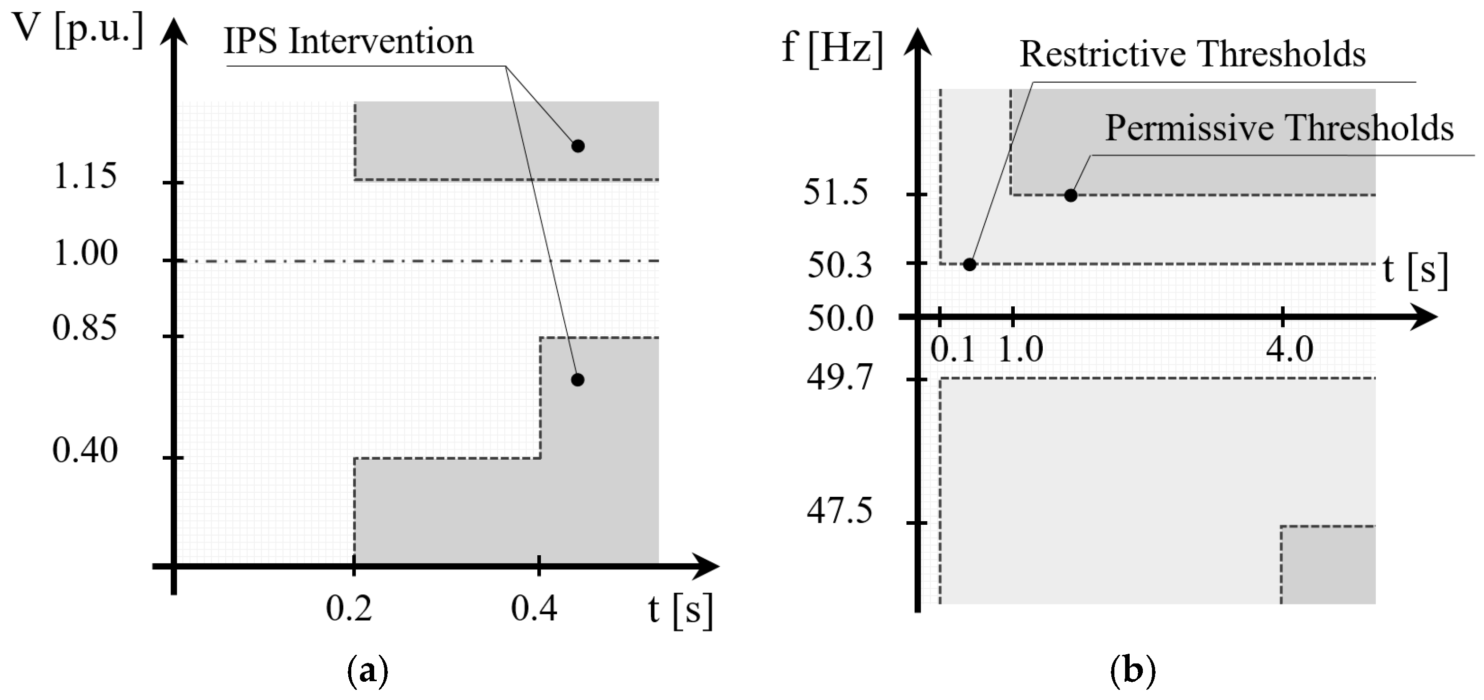
2.2. Interface Protection System for DG

The IPS, as specified in [9], operates as a passive loss-of-main protection, disconnecting generators and storage systems of active end-users in the case of either voltage or frequency violation of acceptable bands. The IPS combines several single protections, implementing the protection thresholds depicted in Figure 2.
For DGs, under-voltage and over-voltage protections are identified with the ANSI/IEEE classification codes 27 and 59, respectively (where ANSI is the American National Standards Institute). The under-voltage protection implements the fault voltage ride through (FVRT) logic. In detail, fast voltage transients, shorter than 0.2 s, may occur without untimely generators disconnection. Otherwise, the IPS operates: (i) in 0.4 s if V < 0.85 p.u.; (ii) in 0.2 s if V < 0.4 p.u.; and (iii) in 0.2 s in the case of voltage permanently higher than 1.15 p.u. The frequency protection refers to the ANSI/IEEE classification code 81 and has the ability to switch between two operation modes, characterized by restrictive or permissive thresholds, respectively. In the former case, the protection operates in 0.1 s in the case f < 49.7 Hz or f > 50.3 Hz, otherwise, the IPS disconnects the generator in either 1 s or 4 s if f is greater than 51.5 Hz or lower than 47.5 Hz respectively. If activated, switching between the IPS operation modes is triggered by a DSO generated external signal. Permissive thresholds have been recently introduced to contribute to the main system stability by: (i) avoiding the nuisance tripping of distributed resources (DG units and ESSs) in the case of small system perturbations (similarly, the FVRT function has been introduced on the under-voltage relay); and (ii) contributing to the frequency regulation in the case of large frequency deviations, according to the stabilizing function discussed in this paper.
Aim of the IPS is the extinction of unintentional islanding supplied by the DG, without using remote communication from other areas of the distribution network. However, the effect of stabilizing functions, which have been introduced in order to reduce perturbations of network parameters (frequency and voltage) in the case of distribution systems events, can affect the correct operation of the IPS, so further active anti-islanding strategies are under investigation [31,32,33,34].

3. ESS Regulating Functions

Standard CEI 0-21 [9] regulates storage systems in a dedicated section, differentiating the connection rules for active power contribution depending on their electrical connection topology: (i) ESS directly interfaced to the end-user AC main bus through a dedicated converter; and (ii) ESS connected to the AC network through the DG inverter, which means that it is placed in parallel with the DC bus of the DG unit, between the energy conversion (e.g., PV panels) and the inverter. It is worth noting that, in the former case, the presence of a local generator is not strictly required. In the case of DC connected ESSs, regulating rules are applied to the unique inverter of the plant, considering both generation and storage. Conversely, the reactive power management is specified by the same reference characteristic for both connection topologies. A synthetic yet exhaustive description of the ESS regulating functions is given below.

3.1. Active Power Regulation of AC Interfaced ESS

In the case an ESS is connected through a dedicated bidirectional converter to the AC bus of an end-user, its reference droop curve for the active power modulation is depicted in Figure 3, as a function of the frequency measured at the converter AC terminals. Reported symbols have the following meaning: (i) PESS is the power injected by the battery (PESS > 0 means battery discharge); (ii) PDMAX (>0) is the maximum discharging power (maximum power injection into the grid) that the storage system has to guarantee in standard operating conditions, i.e., state of charge (SoC) in the range 10%–90%; and (iii) PCMAX (<0) is the maximum charging power (absorbed from the grid) that the storage system has to guarantee in standard operating conditions. Anyhow, the electronic converter rated power must be higher than both PDMAX and |PCMAX|. Frequency thresholds f1, f2, f3 and f4 are reported in Table 2.
The light grey zone represents the possible operating points in steady-state regime. In the case of limited frequency perturbations, which means f within the range f2f3, no regulating actions are required to the ESS and the active power may remain unaltered. Differently, once the under-frequency threshold f2 is reached during the frequency transient (red path, point A in Figure 3), the active power is modulated to provide the regulating action. The operating point is required to evolve towards the corresponding vertex of the quadrilateral, following the trajectory defined by the grey arrow. When the sign of the frequency time derivative changes (e.g., point B), a hysteresis transient is applied to the ESS (similarly to the DG P/f stabilizing regulation) and the just reached active power level has to be maintained for a time duration of 300 s, starting from the time instant the frequency reaches back the rated value with a tolerance of 0.1 Hz (i.e., the operating point enter in the dark grey area, point C).
After the intentional hysteresis, if the frequency transient is over, the active power set point returns to the pre-perturbation value (dashed red line). Differently, in the case a further frequency perturbation occurs before the system has come back to the initial steady-state condition, the ESS is called to maintain a constant output power until its operating point reaches the sloping side of the quadrilateral (dotted red line, point D). Then it has to follow the intersected side until the frequency time derivative changes its sign again (e.g., point E). At the end of the frequency transient, the operating point moves towards the vertical axis (point F) and the system goes back to the initial steady-state condition with hysteresis behavior, as previously described. In the case of f < f1 or f > f4, the stabilizing contribution of the ESS is limited to PDMAX and PCMAX respectively. A similar behavior is required in the case the frequency increases over the over-frequency threshold f3 (e.g., the green path in Figure 3 represents the behavior required to the storage unit in the case an over-frequency exceeding also f4 is measured at the power converter terminals).
The required ESS dynamic should be the same independently of the state of the ESS before the frequency perturbation (charging or discharging). In the case the ESS reaches its minimum or maximum SoC (usually 10%–90%) during the transient, it is called to complete the regulating service with a progressive decrease of the injected or absorbed power, respecting its operating constraints.

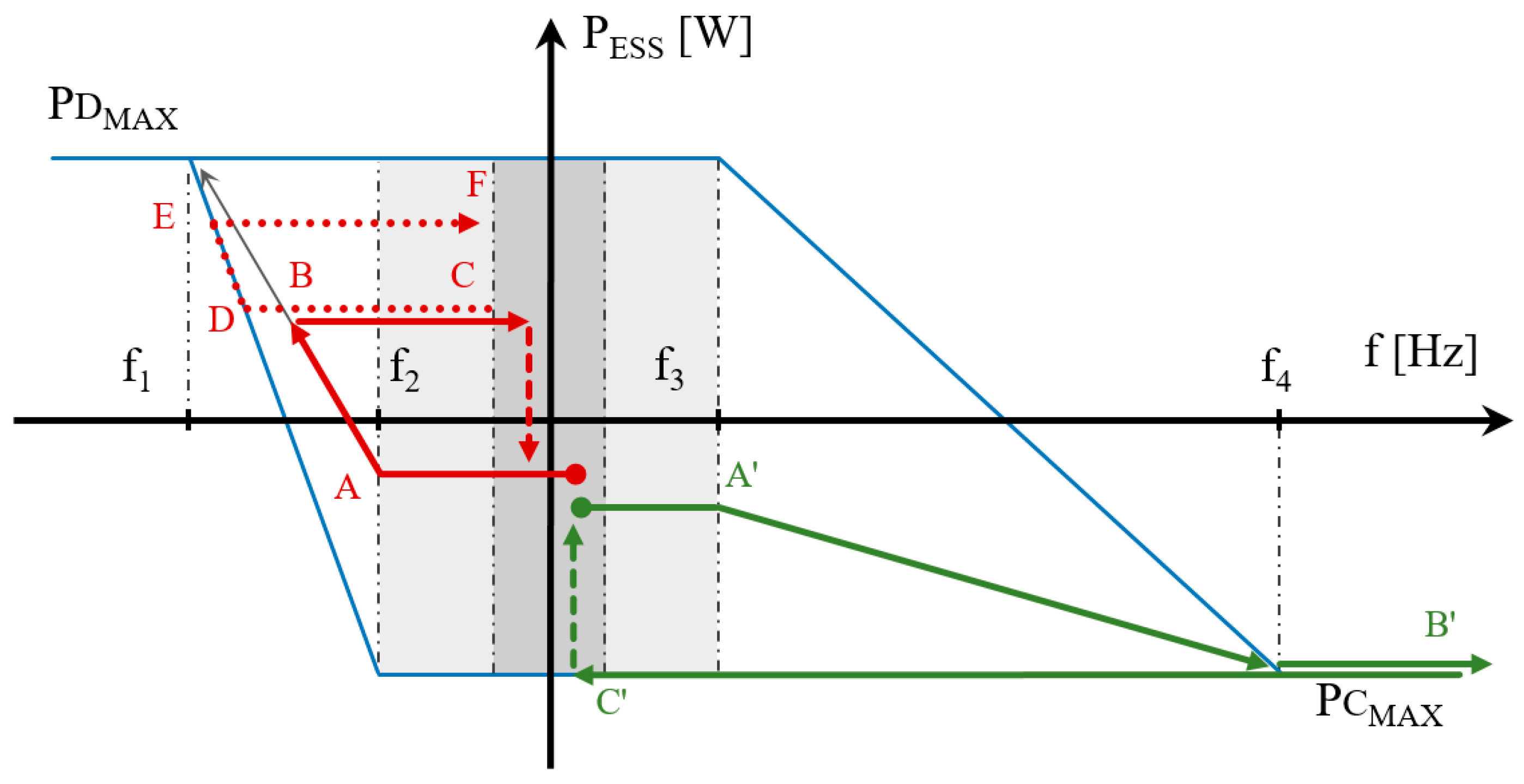
3.2. Active Power Regulation of DC Connected ESS

The case of ESS directly connected to the DC bus of a local static generator differs from the previous scenario since the operating state of the DG has to be considered too. The prescriptions reported in [9] are synthetically depicted in Figure 4, where:
  • PSGS is the total active power injected by the overall generating system (static generator with storage (SGS));
  • PrINV represents the rated power of the electronic converter interconnecting the SGS to the end-user AC bus;
  • PDMAX and PCMAX are the ESS power constraints in discharge and charge, respectively, as mentioned above; and
  • PDG is the actual active power produced by the local generator immediately before the frequency perturbation. The reference thresholds f1, f2, f3 and f4 are unaltered in comparison with the previous subsection discussing AC interfaced ESS, so their values are listed in Table 2.
The light grey region includes the SGS operative points in steady-state regime. Assuming the initial SGS active power equal to PDG (no contribution from the ESS), the red path shows the behavior required to the system during an under-frequency transient. In the case of a severe under-frequency perturbation (f < f2, point A in Figure 4), the converter active power exchange is required to converge to the correspondent vertex of the quadrilateral (i.e., along the grey arrow). Compared with the case of AC coupled ESS, even if the left vertex (towards which the system evolves) continues to be located in (f1; PrINV), the SGS P/f contribution is limited to the sum PDG + PDMAX. Once the operating point reaches this constraint (point B), the SGS is required to lock its power injection, so the operating point can move either to point C in the case the under-frequency becomes deeper, or to point D in the case the frequency time derivative changes its sign. The ESS contribution is unlocked with hysteresis behavior if the operating point returns to the vertical axis: similar to the previous ESS connection topology, an intentional time delay of 300 s is introduced, starting when the operating point returns inside the dark grey region in which the frequency deviation is lower than 0.1 Hz. The active power set point returns to the level before the frequency perturbation once the intentional delay is over (dashed red line).
In the case of a further frequency perturbation before the system stabilization, the SGS operates similarly to the AC coupled ESS described in the previous section.
A dual behavior applies during over-frequency perturbations, even in the case of a power contribution of the ESS immediately before the frequency perturbation. For example, the green path in Figure 4 represents the SGS behavior in the case of severe over-frequency (f > f4), starting from a steady-state condition in which the ESS was charging (PESS < 0), partially absorbing the DG production PDG. The stabilizing contribution is limited to the DG switch off and the ESS operation at its maximum charging power (PSGS = PCMAX). The end-user is free to define the operation sequence between charging the storage system and switching off the local generator, since the standard defines only the overall required active power exchange between the power converter and the AC network. Once the frequency perturbation ends, the regulating contribution is unlocked with hysteresis trend (point C′, operating condition inside the dark grey area).
In the case the SGS DC/AC converter is unidirectional (i.e., the battery is charged only by the local generation, never absorbing power from the AC grid), the lower line moves up to the graphic horizontal axis and consequently the vertex (f4; PCMAX) becomes (f4; 0).

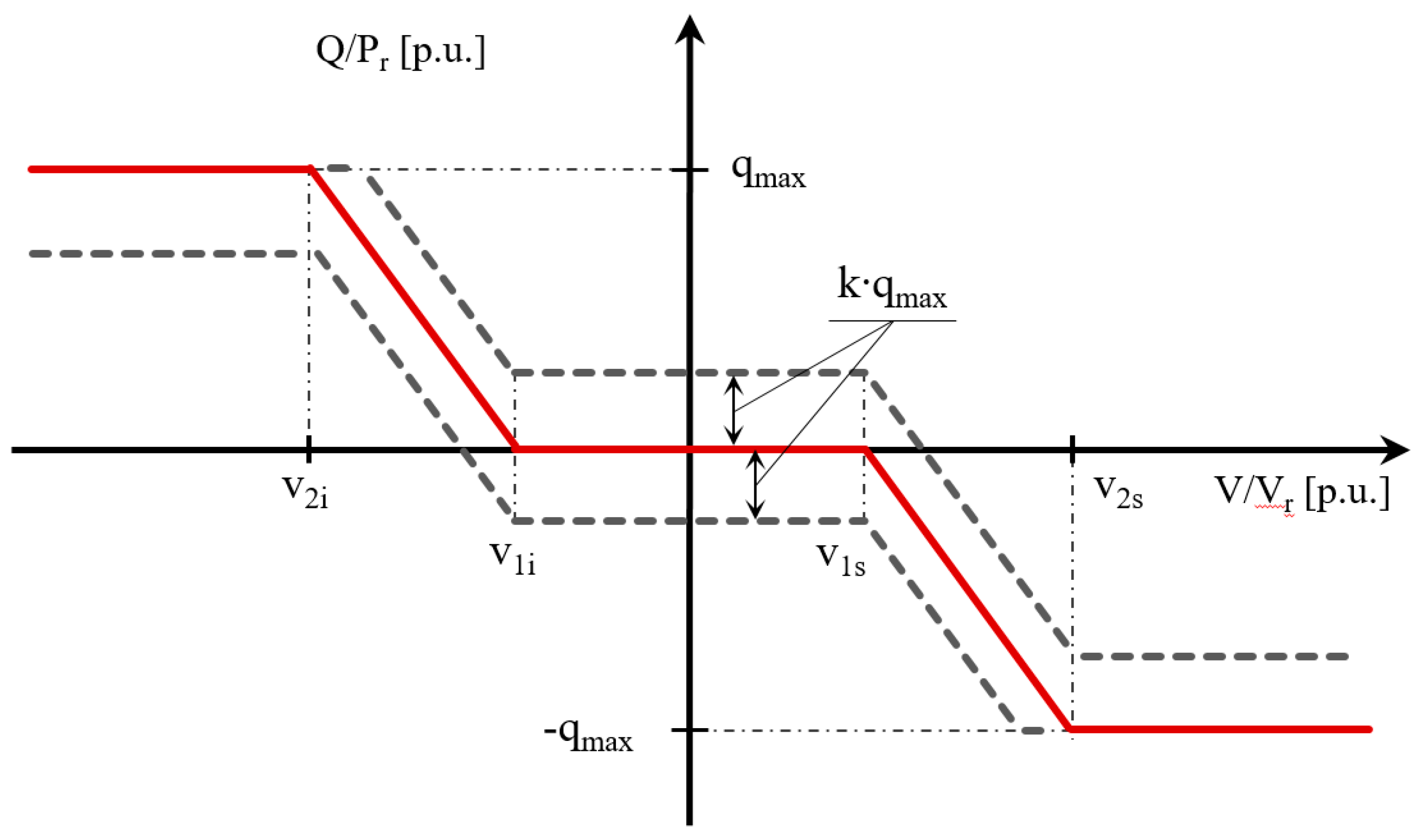
3.3. Reactive Power Regulation

The ESS reactive power modulation according to the measured voltage (Q/V function) is described in [9] with no differences between AC coupled ESSs and DC coupled ESSs. The reference droop curve (plain red line in Figure 5) can be translated up or down depending on a coefficient k provided by the DSO. Thus, the ESS could be required to operate in the region inside the two dashed dark grey curves, thus a reactive contribution could be requested even if the voltage is close to the rated value (inside the dead band v1iv1s). In default conditions, k = 0.

3.4. Interface Protection System for ESSs

As regards the IPS, ESSs are considered similarly to DG units, adopting the operation criteria discussed in Section 2.2.
In the case of ESS coupled with a passive end-user (without local generation), the storage system has to be equipped with its own IPS operating as described in Section 2.2. When the ESS is placed in parallel to a DG unit making use of an own bidirectional power converter (AC coupled ESS), a unique IPS has to be installed downstream the parallel point. In this way, the IPS acts in the case of voltage or frequency perturbations disconnecting both generation unit and storage system. Exceptions are allowed in the case of limited number of small-size power converters (up to three machines in parallel): in this case, each inverter can be provided with its own IPS, but the intervention of a single IPS has to guarantee the disconnection of all the parallel connected inverters.
In the case of ESS connected to the DC side of a local DG, the generation system and the storage unit make use of a unique IPS, normally included in the power converter in the case of domestic-size plants or installed immediately downstream.

4. Case study

An equivalent model, summarizing a realistic LV network (Vr = 0.4 kV), has been assumed as test case for the dynamic root mean square (RMS) simulations (time step 0.1 ms), performed with DIgSILENT PowerFactory 2016 software.
Although the simulation environment allows to model in detail much more complex networks, the authors intentionally considered here a simple LV system to better highlight and discuss the possible interactions among DGs stabilizing functions, generator protections, network equivalent load, and reactive compensation. The overall system depicted in Figure 6 includes:
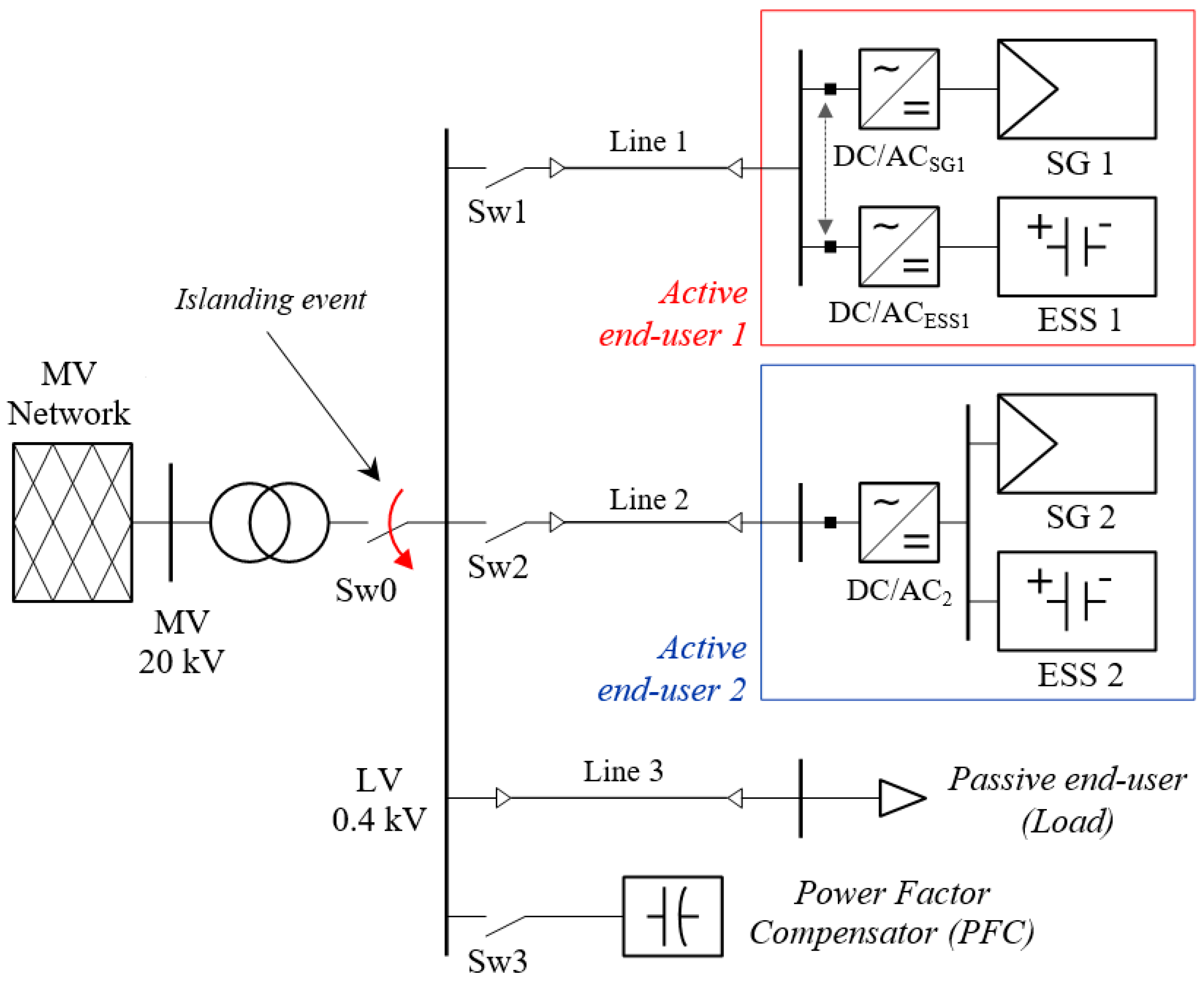
  • A MV Network, supplying the LV subsystem through a generic Dyn11 MV/LV transformer;
  • The equivalent Active end-user 1, consisting of a static generator SG1 with a dedicated DC/AC inverter and an AC coupled storage ESS1;
  • The equivalent Active end-user 2 representing a SGS in which the storage unit ESS2 is DC coupled to the generation unit;
  • An equivalent load representing the overall LV loads; and
  • A centralized power factor compensator (PFC). Different configuration scenarios are investigated considering the presence of Active end-user 1 or 2, and opening and closing the respective switches Sw1 and Sw2.
Active end-user 1 is composed by: (i) the static generator SG1 equipped with a 150 kVA DC/AC converter (variable active power set-points are possible depending on the study cases, while its reactive set-point is zero); and (ii) 60 kVA ESS1, exchanging no power in the initial steady-state condition (maximum available active power equal to ± 60 kW). On the other hand, Active end-user 2 is interfaced with the network through a single converter with rated power equal to 190 kVA. Depending on specific study cases, variable active set-points can be assigned to the DC generator SG2. The unique power converter operates at unit power factor in steady-state conditions. The maximum contribution of ESS2 is ± 60 kW. The rated energy of both ESSs is 100 kWh and the initial SoC is 50%, although these parameters have negligible influence on short-time dynamic simulations.
The equivalent LV load, representing the passive end-users connected to the LV subsystem, absorbs 108 kVA with power factor cos(φ) = 0.93 in rated operating conditions (Vr = 0.4 kV, fr = 50 Hz). The model is able to correctly represent both the static and the dynamic components of passive end-users, so the load behavior, depending on voltage V and frequency f at the supplying node, is suitably taken into account [35,36]. In detail, the static portion (assumed in this work as 40% of the overall load) is modeled as a constant impedance, whereas the dynamic behavior is represented by Equation (1), where Pr and Qr are the active and reactive power in rated operating conditions, respectively, kpv = 1.3, kqv = 2.7, kpf = 0.8, kqf = −2.2 and T1 = 0.1 s.
{ P ( V , f ) = P r ( V V r ) k p v [ 1 + ( f f r ) k p f 1 + s   T 1 ] Q ( V , f ) = Q r ( V V r ) k q v [ 1 + ( f f r ) k q f 1 + s   T 1 ]
The centralized PFC is directly connected to the LV busbar of the secondary substation. It provides 40 kvar reactive power in steady-state operating conditions. Distribution lines are modeled as aluminum cables with a 185 mm2 cross section and 300 m length. Switches Sw1, Sw2 and Sw3 in Figure 6 are open or closed depending on the analyzed scenario. The action of switch Sw0 gives rise to the islanding condition in the LV network. IPSs, represented with black squares, are installed on the AC side of all the DC/AC power converters.
Even if the DG unit rated power is higher than the load absorption, the depicted case study is realistic, since: (i) grid codes [8,9] usually do not avoid the connection of DG units with size higher than the end-user rated power, if this does not result in distribution line overloading or voltage regulation issues; and (ii) the time variation of both load and DG primary source has to be considered, so conditions in which the local generation could largely overpass the load absorption normally occur (e.g., the central part of a weekday for households, Sundays for factories).

Generator Model

All the electronic DC/AC converters represented in the case study network of Figure 6 are governed in the simulating software by opportune dedicated models performing the above described regulating functions (P/f and Q/V). According to the grid standards, all the converters operate as current-controlled devices. Each converter is driven by the general control scheme of Figure 7, in which double framed blocks represent physical elements. For instance, the phase-locked loop (PLL) and the voltage measurement device (Voltage Measure) are locally installed at the terminals of each power converter (or inside the inverter) and provide: (i) the phase angle of the positive sequence voltage ( φ V ¯ ) for the converter correct synchronization with the network [37]; (ii) the frequency measure (f); and (iii) the positive sequence voltage ( V ¯ ). Instead, power sources of Figure 6 (SG1, SG2, ESS1 and ESS2) are modeled as DC voltage sources (devoid of power regulations or set-points).
Making use of the native DIgSILENT Simulation Language (DSL), control blocks “droop P/f” and “droop Q/V” actuate the active and reactive power regulations respectively, according to the above described behaviors required to local plants. For each converter, the related control blocks define the active (P) and reactive (Q) power set-points as function of f and V. As described in the previous sections, these functions differ among the converters associated to the DG unit (DC/ACSG1 in Figure 6), to the AC interfaced ESS (DC/ACESS1) and to the static generator with DC coupled storage (DC/AC2). Consequently, for each source type, dedicated DSL expressions are defined in the droop blocks. After that, the power output signals are converted into a current phasor I ¯ in the d-q coordinate system by the S ¯ / I ¯ block to drive the DC/AC current controlled converters. For each inverter, the current signal reference is limited to represent the corresponding converter capability curve, according to [9].
Since the single framed blocks are implemented in the software native programming language, their graphic representations making use of elementary elements are not feasible. The authors individually tested each block operation and the overall controller response to verify the complete compliance with current grid code requirements.

5. Simulation and Results

Simulations reported in the paper investigate both an AC connected ESS and a DC connected ESS, as defined in the current standards depending on the storage unit point of coupling:
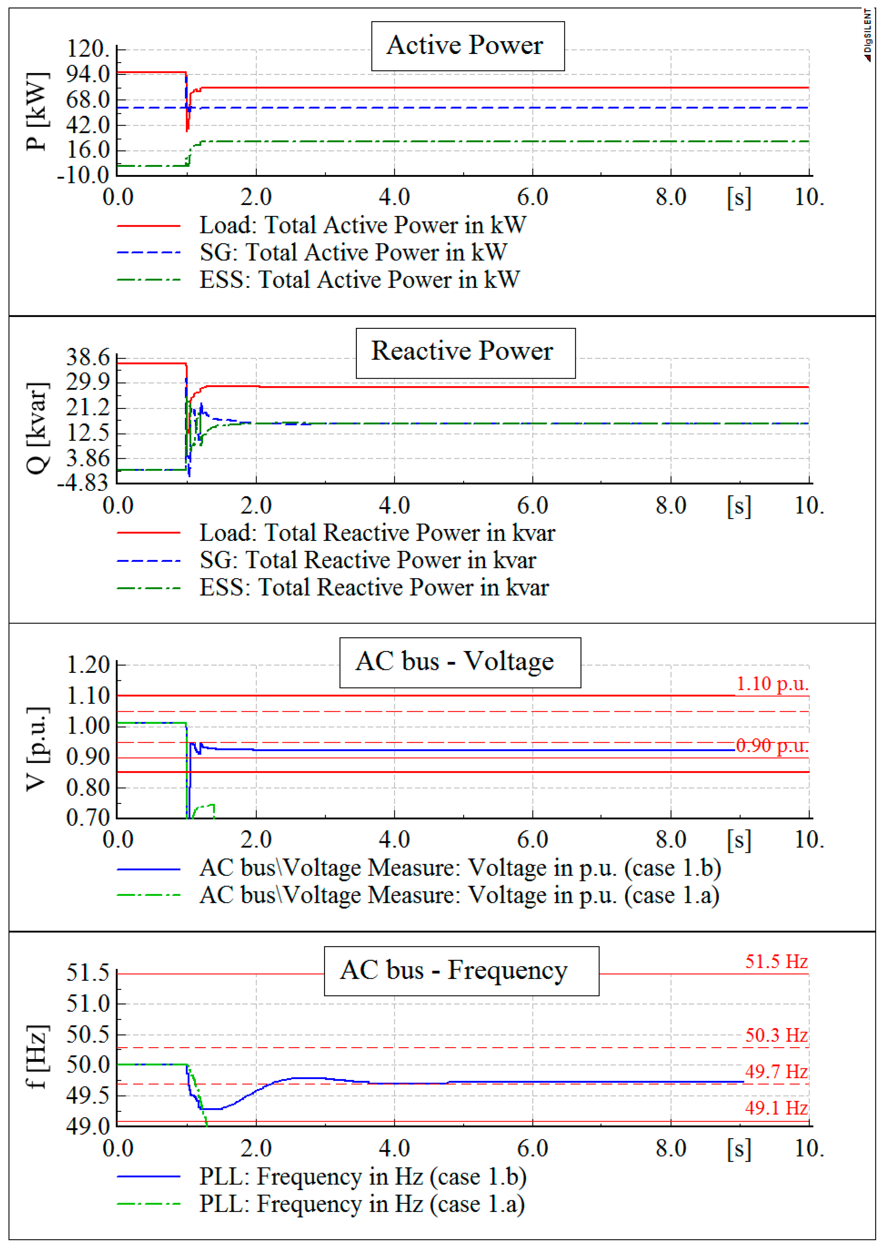
  • The former case considers the AC coupled ESS, i.e., Active end-user 1 in operation and Active end-user 2 out of service (Sw1 closed, Sw2 open); and
  • The latter case represents the DC coupled ESS, i.e., Active end-user 2 connected and Active end-user 1 out of service (Sw1 open, Sw2 closed).
The equivalent load is permanently connected, whereas the PFC can be in or out of service depending on the specific sub-scenario.
The characterizing event consists in opening Sw0 (Figure 6) at t = 1 s, so the LV network experiences a temporary islanded configuration. The operation of Sw0 could be a triggered by an equipment failure, the incorrect operation of the protection system or the activation of other relays acting on the same circuit breaker (e.g., a residual current protection preventing minor electrical leakage). The study aims at demonstrating that ESSs have a significant role in inhibiting the IPS intervention, so a portion of LV network could remain supplied by local units (storage and DG) for a not negligible duration, with increased risk for stability and safety.

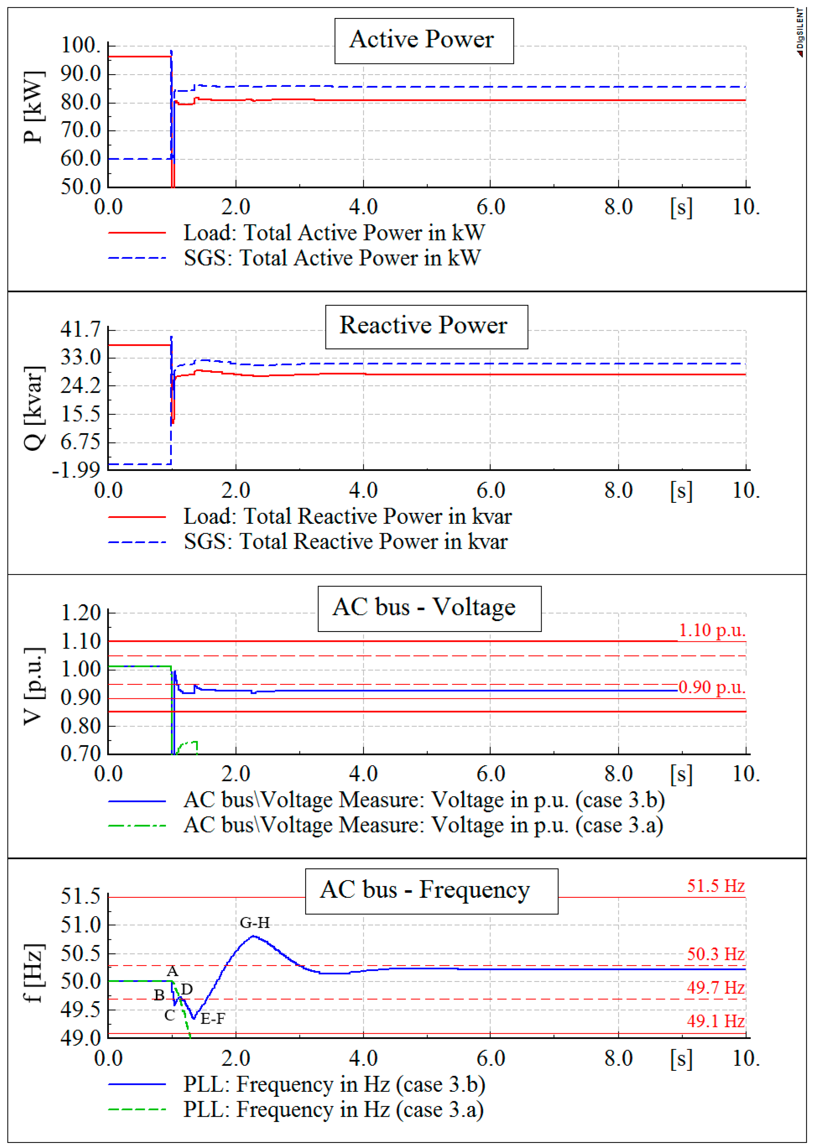
5.1. AC Coupled ESS (Active End-User 1)

In this scenario, SG1 (Figure 6) is permanently connected with activated stabilizing regulations (P/f, Q/V). Two power set-points have been considered: 60 kW (Cases 1.a to 1.d) and 140 kW (Cases 2.a–2.d). These levels of active power generation are equal to 60% and 140% of the rated load respectively. In this way, network behaviors are investigated in the case of both deficit and surplus of generation at the moment of island separation. Different subcases have been taken into account as listed in Table 3, taking into account: (i) the availability of the ESS during transients (max ± 60 kW), with active power set-point in the initial steady-state conditions equal to 0; and (ii) the status of switch Sw3, which determines if the PFC is in or out of service.
Simulation results are summarized in the last column of Table 3. In all the simulations below, the loss-of-main protection is considered ineffective (i.e., no island detection, indicated as “NO” in the last column) if it does not disconnect the local units in less than 5 s from the islanding formation.
In the case the overall LV network generation is lower than the load absorption at the islanding event, the contribution of the sole DG unit (Case 1.a) is not enough to ensure the island stability. Since the DG unit, according to presently applied grid codes, is not required to modify its active output in the case of under-frequency, the deficit in terms of active power allows the protections to correctly operate, since a heavy frequency drop occurs, as depicted in the last subplot of Figure 8 (dash-dot green line).
Connecting an AC coupled ESS with regulating capabilities, a sensibly different behavior appears. Referring to the case study illustrated in Figure 6, network operating conditions with DG and ESS supplying in parallel the islanded system (Case 1.b) are represented in Figure 8. The picture reports in order: (i) active power of load, SG and ESS (Active end-user 1); (ii) reactive power contributions of the units above mentioned; (iii) local voltage measured at the AC side of the DC/AC converters (where the IPS operates); and (iv) frequency trend measured at the same point. As shown in the first subfigure, the ESS supplies a fundamental contribution to the overall active power balancing: according to its SoC, an active power injection (dash-dot green line) is provided as consequence of the frequency perturbation, compensating the generation deficit. The load dependence on frequency and voltage further contributes in the active power balancing, resulting in a reduced absorption after the islanding event. Meanwhile, the load reactive demand is provided by both the SG and the ESS, depending on their size.
Voltage and frequency trends evaluated in Case 1.b are compared, in the last subplots, with those of the previously described Case 1.a. In details, V and f are maintained within the admitted bands, dangerously inhibiting the IPS intervention during the transient. Even if the ESS contribution in stabilizing the islanded network operating conditions depends on the ESS size, its connection undoubtedly increases the risk of IPSs failure. Whether a PFC is installed (Cases 1.c and 1.d), no appreciable differences are experienced, even if better reactive power balance conditions could be reached.
In the case the DG active power production exceeds the load absorption, undesired conditions occur in all the examined cases, which means that the sole P/f regulation applied to the generation unit already leads to a balanced configuration (Case 2.a). In addition, a reactive power equilibrium is obtained due to the Q/V regulation. The presence of an ESS in Case 2.b further increases the islanding risk, entailing a lower SG active power reduction as regards Case 2.a, i.e., a reduced amplitude of the frequency perturbation. During the over-frequency transient, the storage is asked to charge according to its P/f function, contributing to the active power balance.
Additionally, the connection of a PFC (Cases 2.c and 2.d) could provide a better reactive power balance, potentially reflecting in an undesired contribution to the islanding stabilization since the voltage level is maintained closer to the rated value. However, in the analyzed scenarios, no appreciable differences in terms of IPS effectiveness are experienced.
It should be noted that IPSs operating with restrictive thresholds on the frequency relay could be more effective in identifying unintentional islanding conditions, since both the admitted frequency range and the triggering time are reduced. However, the provisions for maintaining the main system stability, i.e., both avoiding remote resources disconnection in the case of minor frequency deviations and activating stabilizing functions to contribute to the voltage/frequency regulation, need IPSs to operate with permissive thresholds, with consequent increased risk of unintentional islanding.

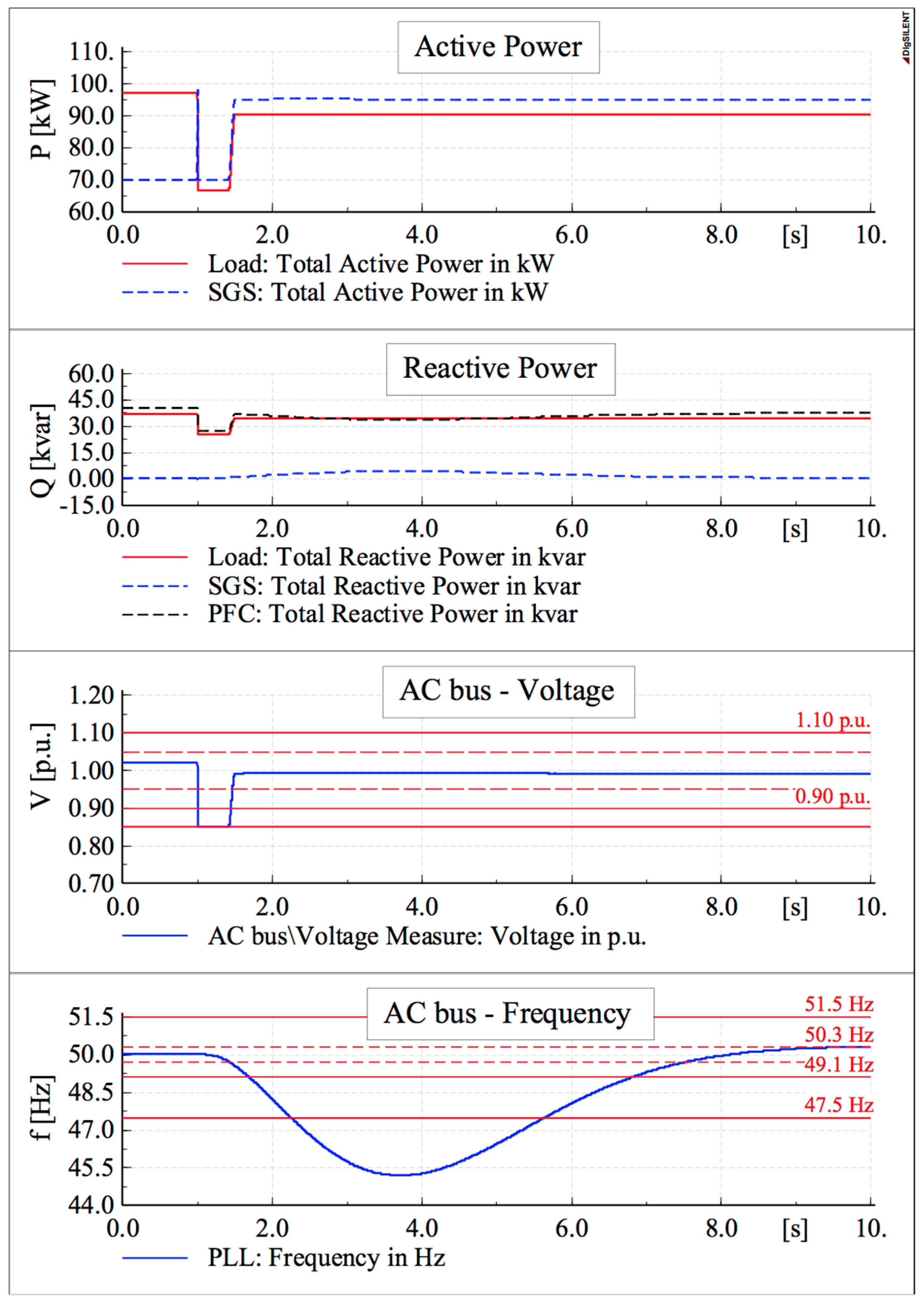
5.2. DC Coupled ESS (Active End-User 2)

This section focuses on the behavior of the sole Active end-user 2 as generating unit. As described in Table 4, the ESS contribution is considered (ON) or inhibited (OFF), emphasizing the ESS contribution in maintaining the islanded network stability. In the initial steady-state condition, generator SG2 has been supposed to work with two reference active power levels, similarly to the previous section. Achieved results are summarized in the last column of Table 4, with the same meaning as the already discussed Table 3.
Simulations reveal that main results obtained for AC coupled ESS are confirmed also considering DC coupled ESS. No sensible differences in terms of IPS effectiveness are appreciable, as could be seen comparing Table 4 with Table 3. In particular, Case 3.b (illustrated in Figure 9) is a noteworthy example since the ESS active power contribution is supplied as a consequence of both an under-frequency perturbation and a subsequent over-frequency transient. This confirms the role of SGS frequency regulating function P/f in unintentional islanding, in particular the ability in dumping frequency oscillations. Figure 9 reports the load and the SGS active and reactive power in the first two subfigures from the top, where the difference between the production from SGS and the absorption by the load is attributable to the line losses. In the lower subplots, the AC side voltage and frequency trends in Case 3.b are compared with the ones in the corresponding scenario without storage (Case 3.a). Some important phases of the frequency transient in Case 3.b are indicated with letters AH in Figure 9. Correspondingly, Figure 10 reports, in the f-P coordinate system, the dynamic behavior of the SGS operating point, in terms of active power reference signal. In addition to the enlarged representation, the same trend is depicted in the box on the right referring to the whole operative quadrilateral of the SGS (Figure 4). The analysis of the obtained trajectory confirms that the DSL programmed controllers briefly represented in Figure 7 effectively operates according to the rules explained in Section 3.2.
The initial operating condition is indicated with A. Immediately after t = 1 s, a frequency drop deeper than 0.3 Hz (point B) requires the SGS to increase the injected power (contribution provided by the storage unit) to balance the load absorption, which is in the meantime decreasing as a consequence of the voltage drop. In this phase, the operating point moves along the grey trajectory defined in Figure 4 up to point C. The hysteresis behavior fixes the power set-point after the first inversion of the frequency time derivative occurring at about t = 1.04 s (point C). Point C represents a transient condition, since the active power injected by the SGS has a ripple around the set-point value reported in Figure 10 (i.e., 83.7 kW). As a result, the frequency initially tends to increase (reaching point D) but successively (at about t = 1.13 s) decreases again as the actual active power reaches the set-point value 83.7 kW. Once point E is reached working at locked active power, the operating points follow the trajectory defined by the left sloping side of the quadrilateral defined by [9], up to point F (85.9 kW). During the following frequency rise, the power set-point is locked again until an over-frequency exceeding the right sloping side of the quadrilateral (f = 50.8 Hz) causes its small reduction at t = 2.25 s (point G) to point H. Finally, a stable islanded condition is reached and the SGS active power remains locked until the frequency returns at its rated value with tolerance of 0.1 Hz for at least 300 s.
Similarly, the reactive power regulation is operated, since the voltage is lower than the activation threshold of the Q/V function (0.95 p.u., corresponding to the horizontal dashed red line in the third subfigure of Figure 9).
As in Cases 1.c and 1.d, the PFC connection increases the reactive power balance and consequently reduces the voltage perturbation immediately after the switching event triggering the island formation. This results in a stabilizing effect, inhibiting the correct operation of IPSs. Thus, in the case either the load operates at high power factor or a PFC is connected, an intentional delay on the Q/V stabilizing function could result ineffective in avoiding the IPS failure.
Similar to AC coupled ESS, in the case of islanding with generation surplus, the DC coupled ESS helps the DG unit in maintaining a stable condition since the amplitude and duration of the frequency transient results lower. However, it is confirmed that the sole DG with P/f stabilizing function can supply the islanded system in the simulated working conditions.

5.3. Influence of Q/V Regulation Delay

It is worth noting that both CENELEC guidelines [5] and some national grid codes (e.g., [8]) have recently introduced intentional delays in applying stabilizing functions to reduce the risk of unintentional islanding (this specific requirement is not applied to previously connected storage systems). It is not advisable to implement a delay on the P/f function in providing primary control regulation to the main grid as demonstrated, for instance, in [4,38], showing how a fast and precise active power response directly implicates reductions in the frequency perturbation width. Consequently, for new installations, the Q/V stabilizing function is required to dynamically behave as a first order filter, with time constant configurable in the range of 3–60 s.
Differently from the DG units, storage systems may be much more effective in limiting the frequency perturbation width, since both positive and negative active power contributions can be provided. For instance, referring to a DC coupled ESS, operating in accordance with the required path described in Figure 4, it should be noted that the dynamic trend of the SGS strongly depends on the operating conditions of both the DG unit (PDG, according to the primary source availability) and the storage device (PDMAX and PCMAX, depending on the internal SoC). Issues having influence on the unintentional islanding stability are:
  • Slope of lateral sides of the operating quadrilateral (Figure 4). It should be noted that in LV systems, the P/f function has impact not only on the frequency stability, but also on network voltage perturbations due to the high R/X ratio. Since the frequency coordinates on the horizontal axis are defined by the grid code [9], increasing PDG, PDMAX and PCMAX means increasing the response of active end-users to frequency perturbations. This could result in frequency/voltage instability (triggering the IPS activation) if the reactive power response of active end-users to voltage perturbations is slowed down through a low-pass filter.
  • Effective availability of active power in the disconnected portion of the network: in the case PDG + PDMAX is close to the load absorption, this condition masks the instability caused by the slope of lateral sides of the operating quadrilateral of Figure 4, limiting the response of the ESS immediately after the network portion separation.
These remarks are confirmed by the simulation results reported in Figure 11, in which PDG = 70 kW, PDMAX = 25 kW, load rated active power is 100 kW and the capacitor bank is connected. Since the ESS response to the network perturbations is limited by the local availability of active power, the range of variation of both frequency and voltage is narrow enough not to trigger the IPS activation (considering ANSI IEEE 81 protection set with permissible thresholds). In particular, the under-frequency perturbation exceeds the permissive frequency threshold within 2 s and 6 s, lasting less than the admitted time duration for that threshold (4 s). Consequently, even in the case of delayed reactive power response according to [5], the separated network portion is supplied by the DG unit equipped with the DC coupled ESS for a not negligible duration, which is an unacceptable condition for safety issues. Similar results are obtainable in the case of AC coupled ESS.

6. Conclusions

This paper deals with the application of the recently revised connection standards for dispersed generators and storage units in LV distribution systems, which define new requirements in particular for ESSs. Regulating actions are introduced aiming at enhancing the contribution of local storage devices to the grid stability by modifying active and reactive power exchanges depending on local frequency and voltage variations. In particular, the objective of this work is verifying whether such stabilizing functions may influence the correct operation of currently required loss-of-main protections, which means network safety. In this perspective, the dynamic behaviors defined by recently revised standards for different active components (DG units, AC coupled storage systems and DC coupled storage systems) have been implemented through suitable controllers using the simulation software native programming language.
Several scenarios have been considered for an equivalent active distribution network to investigate the consequences of the local control on the network stability, focusing on the separation of the LV system from the main grid. In the case the power production overcomes the load demand, results show that failures in the interface protections may occur both with and without the ESS, due to the stabilizing functions provided by the sole local generation. Even considering mainly passive networks, the presence of storage units could dramatically increase the risk of unintentional islanding, since they tend to quickly compensate the power unbalance at the time of network separation. In both cases, the presently adopted Interface Protections Systems may not fully ensure the loss-of-main detection in modern LV systems hosting distributed generation and storage devices. Even imposing to active end-users an intentional slow response to the reactive power regulation, after the islanding event the separated portion may still experience stable operating conditions, with voltage and frequency remaining within the admitted ranges.
As final result, IPSs based on passive relays can be effective in networks with a limited penetration level of dispersed generation and storage systems. Otherwise, considering the recent evolution of distribution systems, other approaches have to be introduced in future grid codes in order to eliminate or at least minimize the interface protection not-detection zone. To this aim, active protections (e.g., observing the network equivalent impedance through a high frequency measure based on an intentional current injection) and reliable communication channels between DSOs and end-users are under consideration.

Author Contributions

Fabio Bignucolo, Alberto Cerretti and Roberto Turri conceived the project. Fabio Bignucolo, Andrea Savio and Massimiliano Coppo realized the dynamic models in DIgSILENT PowerFactory 2016, making use of the software programming language to reproduce the dynamic behaviors required to active end users by present grid codes. All the authors wrote, reviewed and approved the manuscript.

Conflicts of Interest

The authors declare no conflict of interest.

References

  1. Divya, K.C.; Østergaard, J. Battery energy storage technology for power systems—An overview. Electr. Power Syst. Res. 2009, 79, 511–520. [Google Scholar] [CrossRef]
  2. Bignucolo, F.; Caldon, R.; Carradore, L.; Sacco, A.; Turri, R. Role of storage systems and market based ancillary services in active distribution networks management. In Proceedings of the 43rd International Conference on Large High Voltage Electric Systems (CIGRE), Paris, France, 22–27 August 2010.
  3. Bignucolo, F.; Bertoluzzo, M.; Fontana, C. Applications of the solid state transformer concept in the electrical power system. In Proceedings of the International Annual Conference (AEIT), Napoli, Italy, 14–16 October 2015.
  4. Bignucolo, F.; Caldon, R.; Coppo, M.; Pasut, F.; Pettinà, M. Integration of Lithium-Ion Battery Storage Systems in Hydroelectric Plants for Supplying Primary Control Reserve. Energies 2017, 10, 98. [Google Scholar] [CrossRef]
  5. European Committee for Electrotechnical Standardization, Technical Specification CENELEC TS 50549-1. Requirements for Generating Plants to Be Connected in Parallel with Distribution Networks—Part 1: Connection to a LV Distribution Network above 16 A; CENELEC: Brussels, Belgium, 2015. [Google Scholar]
  6. European Committee for Electrotechnical Standardization, Technical Specification CENELEC TS 50549-2. Requirements for Generating Plants to Be Connected in Parallel with Distribution Networks–Part 2: Connection to a MV Distribution System; CENELEC: Brussels, Belgium, 2015. [Google Scholar]
  7. European Committee for Electrotechnical Standardization, European Standard CENELEC EN 50438. Requirements for Micro-Generating Plants to Be Connected in Parallel with Public Low-Voltage Distribution Networks; CENELEC: Brussels, Belgium, 2013. [Google Scholar]
  8. Comitato Elettrotecnico Italiano, CEI 0–16. Reference Technical Rules for the Connection of Active and Passive Consumers to the HV and MV Electrical Networks of Distribution Company; CEI: Milan, Italy, 2016. [Google Scholar]
  9. Comitato Elettrotecnico Italiano, CEI 0–21. Reference Technical Rules for the Connection of Active and Passive Users to the LV Electrical Utilities; CEI: Milan, Italy, 2016. [Google Scholar]
  10. Bignucolo, F.; Raciti, A.; Caldon, R. A control strategy for the management of islanded networks with renewables and storage systems. In Proceeding of the 2014 49th International Universities Power Engineering Conference (UPEC), Cluj-Napoca, Romania, 2–5 September 2014.
  11. Bignucolo, F.; Raciti, A.; Caldon, R. Coordinating active and reactive energy balances in islanded networks supported by renewables and BESS. In Proceeding of the 3rd Renewable Power Generation Conference (RPG 2014), Naples, Italy, 24–25 September 2014.
  12. Yong, W.K.; Lim, Y.; Morris, S. Allowing islanded operation of photovoltaic system with the aid of droop-controlled inverter. In Proceedings of the 2014 IEEE Conference on Energy Conversion (CENCON), Johor Bahru, Malaysia, 13–14 October 2014; pp. 248–253.
  13. Abusief, F.; Caldon, R.; Bignucolo, F. Remote islanded distribution networks supplied by BESS integrated PV generation units. In Proceedings of the 2016 IEEE 16th International Conference on Environment and Electrical Engineering (EEEIC), Florence, Italy, 7–10 June 2016.
  14. Bignucolo, F.; Caldon, R.; Frigo, M.; Morini, A.; Pitto, A.; Silvestro, F. Impact of distributed generation on network security: Effects on loss-of-main protection reliability. In Proceedings of the Universities Power Engineering Conference (UPEC), Padova, Italy, 1–4 September 2008.
  15. Caldon, R.; Coppo, M.; Sgarbossa, R.; Turri, R. Risk of unintentional islanding in LV distribution networks with inverter-based DGs. In Proceedings of the 48th International Power Engineering Conference, Dublin, UK, 2–5 September 2013.
  16. Amadei, F.; Cerretti, A.; Coppo, M.; Mattavelli, P.; Sgarbossa, R.; Turri, R. Temporary islanding operations of MV/LV active distribution networks under fault conditions. In Proceedings of the 49th International Universities Power Engineering Conference, Cluj-Napoca, Romania, 2–5 September 2014.
  17. Cerretti, A.; D’Orazio, L.; Pezzato, C.; Sapienza, G.; Valvo, G.; Camalleri, N.; Mattavelli, P.; Sgarbossa, R.; Turri, R.; De Berardinis, E. Uncontrolled islanding operations of MV/LV active distribution networks. In Proceedings of the 2015 IEEE Eindhoven PowerTech, Eindhoven, The Netherlands, 29 June–2 July 2015.
  18. Sgarbossa, R.; Lissandron, S.; Mattavelli, P.; Turri, R.; Cerretti, A. Analysis of ΔP-ΔQ area of uncontrolled islanding in low voltage grids with PV generators. IEEE Trans. Ind. Appl. 2016, 52, 2387–2396. [Google Scholar] [CrossRef]
  19. Bignucolo, F.; Cerretti, A.; Coppo, M.; Savio, A.; Turri, R. Impact of Distributed Generation Grid Code Requirements on Islanding Detection in LV Networks. Energies 2017, 10, 156. [Google Scholar] [CrossRef]
  20. Bignucolo, F.; Savio, A.; Turri, R.; Cerretti, A. Undesired islanding of MV networks sustained by LV dispersed generators compliant with present grid code requirements. In Proceedings of the 51st International Universities UPEC, Coimbra, Portugal, 6–9 September 2016.
  21. Koohi-Kamali, S.; Rahim, N.A. Coordinated control of smart microgrid during and after islanding operation to prevent under frequency load shedding using energy storage system. Energy Convers. Manag. 2016, 127, 623–646. [Google Scholar] [CrossRef]
  22. Kermani, M. Transient voltage and frequency stability of an isolated microgrid based on energy storage systems. In Proceedings of the 2016 IEEE 16th International Conference on Environment and Electrical Engineering (EEEIC), Florence, Italy, 7–10 June 2016.
  23. Ballal, M.S.; Bhadane, K.V.; Moharil, R.M.; Suryawanshi, H.M. A control and protection model for the distributed generation and energy storage systems in microgrids. J. Power Electron. 2016, 16, 748–759. [Google Scholar] [CrossRef]
  24. Hassan Youssef, K. Optimal management of unbalanced smart microgrids for scheduled and unscheduled multiple transitions between grid-connected and islanded modes. Electr. Power Syst. Res. 2016, 141, 104–113. [Google Scholar] [CrossRef]
  25. Mehrasa, M.; Pouresmaeil, E.; Jørgensen, B.N.; Catalão, J.P.S. A control plan for the stable operation of microgrids during grid-connected and islanded modes. Electr. Power Syst. Res. 2015, 129, 10–22. [Google Scholar] [CrossRef]
  26. Shin, S.-S.; Oh, J.-S.; Jang, S.-H.; Chae, W.-K.; Park, J.-H.; Kim, J.-E. A fault analysis on AC microgrid with distributed generations. J. Electr. Eng. Technol. 2016, 11, 1600–1609. [Google Scholar] [CrossRef]
  27. Bignucolo, F.; Savio, A.; Caldon, R.; Cerretti, A. Effects of Average Power Factor Management in Distribution Systems with Dispersed Generation. In Proceedings of the AEIT International Annual Conference, Capri, Italy, 5–7 October 2016.
  28. Blazic, B.; Papic, I. Voltage profile support in distribution networks—influence of the network R/X ratio. In Proceedings of the 13th Power Electronics and Motion Control (EPE-PEMC) Conference, Poznan, Poland, 1–3 September 2008; pp. 2510–2515.
  29. Vandoorn, T.L.; Renders, B.; Degroote, L.; Meersman, B.; Vandevelde, L. Active load control in islanded microgrids based on the grid voltage. IEEE Trans. Smart Grid 2011, 2, 139–151. [Google Scholar] [CrossRef]
  30. Latif, A.; Gawlik, W.; Palensky, P. Quantification and mitigation of unfairness in active power curtailment of rooftop photovoltaic systems using sensitivity based coordinated control. Energies 2016, 9. [Google Scholar] [CrossRef]
  31. Ahmad, A.; Rajaji, L. Anti-islanding technique for grid connected residential solar inverter system. In Proceedings of the Institution of Engineering and Technology (IET) Chennai Fourth International Conference on Sustainable Energy and Intelligent Systems (SEISCON), Chennai, India, 12–14 December 2013; pp. 114–118.
  32. Cataliotti, A.; Cosentino, V.; Guaiana, S.; Di Cara, D.; Panzavecchia, N.; Tinè, G. An interface protection system with power line communication for distributed generators remote control. In Proceedings of the 2014 IEEE International Workshop on Applied Measurements for Power Systems (AMPS), Aachen, Germany, 24–26 September 2014.
  33. Bufano, V.; Camalleri, N.; Cerretti, A.; D’Adamo, C.; D’Orazio, L.; Pezzato, C.; De Berardinis, E. Risk of uncontrolled islanding on active distribution networks short term countermeasures taken by Enel Distribuzione. In Proceedings of the 23nd International Conference and Exhibition on Electricity Distribution, Lyon, France, 15–18 June 2015.
  34. Bufano, V.; D’Adamo, C.; D’Orazio, L.; D’Orinzi, C. Innovative solutions to control unintentional islanding on LV network with high penetration of distributed generation. In Proceedings of the 22nd International Conference and Exhibition on Electricity Distribution (CIRED), Stockholm, Sweden, 10–13 June 2013.
  35. Savio, A.; Bignucolo, F.; Sgarbossa, R.; Mattavelli, P.; Cerretti, A.; Turri, R. A novel measurement-based procedure for load dynamic equivalent identification. In Proceedings of the 2015 IEEE 1st International Forum on Research and Technologies for Society and Industry Leveraging a better tomorrow (RTSI), Turin, Italy, 16–18 September 2015; pp. 274–279.
  36. Milanović, J.; Matevosiyan, J.; Gaikwad, A. TB 566: Modeling and Aggregation of Loads in Flexible Power Networks —WG C4.605; Technical Report; International Council on Large Electric systems (CIGRE): Paris, France, 2014. [Google Scholar]
  37. Savio, A.; Bignucolo, F.; Caldon, R. Contribution of MV static distributed generation to voltage unbalance mitigation. In Proceedings of the AEIT International Annual Conference, Capri, Italy, 5–7 October 2016.
  38. Borsche, T.S.; Ulbig, A.; Andersson, G. Impact of Frequency Control Reserve Provision by Storage Systems on Power System Operation. IFAC Proc. Vol. 2014, 47, 4038–4043. [Google Scholar] [CrossRef]
Figure 1. Power regulation characteristic required by [9] to DG units: (a) P/f activation thresholds and active power hysteresis behavior (time duration of 300 s); and (b) Q/V thresholds and reactive power modulation (Q/Pr > 0 means a DG reactive behavior equivalent to a capacitive absorption).
Energies 10 00387 g001
Figure 2. Interface protection system (IPS) characteristics and applied thresholds: (a) voltage thresholds implementing the fault voltage ride through (FVRT) function to prevent DG disconnection in the case of fast voltage variations; and (b) frequency restrictive and permissive thresholds, activated according to distribution system operator (DSO) requirements (connection rules or DSO external signal).
Energies 10 00387 g002
Figure 3. Active power regulation required by [9] to AC coupled energy storage systems (ESSs) (P/f function). Red and green lines represent possible behaviors in the case of under- and over-frequency perturbations, respectively.
Energies 10 00387 g003
Figure 4. Active power regulation required by [9] to the static generators including the DC coupled storage system (P/f function). The operating curve is influenced by the generator operating condition PDG. Red and green lines represent possible behaviors in the case of under- and over-frequency perturbations, respectively.
Energies 10 00387 g004
Figure 5. Reactive power regulation required by [9] to ESSs, either AC coupled or connected to the DC internal bus of a DG unit (Q/V function). Default value of k is 0.
Energies 10 00387 g005
Figure 6. Equivalent LV network. The simplified scheme is representative of both a portion of the LV network and a single active end-user.
Energies 10 00387 g006
Figure 7. Control scheme of the static converters. Depending on the controlled converter, the mathematical formulations of required regulating functions are implemented inside blocks droop P/f and droop Q/V, making use of the DIgSILENT simulation language (DSL).
Energies 10 00387 g007
Figure 8. Simulation results in Case 1.b: active and reactive power trends of load, static generator and ESS are reported in the first two subfigures. Voltage and frequency time trend measured at the generator terminal are reported with plane lines in the last two subfigures (in these representations, dash-dotted green lines refer to Case 1.a, in which the ESS is switched off).
Energies 10 00387 g008
Figure 9. Simulation results in Case 3.b: active and reactive power trends of both load and static generator (including the DC coupled storage system) are reported in the first two subfigures. Voltage and frequency time trend measured at the generator terminal are reported with plane lines in the last two subfigures (in these representations, dash-dotted green lines refer to Case 3.a, in which the ESS is switched off).
Energies 10 00387 g009
Figure 10. f-P plot representing the active power set-point assigned to Active end-user 2 in Case 3.b. In the frame on the left, the frequency trend of Figure 9 is detailed between 1 s and 2.5 s (with the corresponding points AH), whereas the right frame reports the system trajectory with reference to the quadrilateral defined by the considered grid code [9], as introduced in Figure 4.
Energies 10 00387 g010
Figure 11. Power, voltage and frequency trends in the case of a SGS performing the Q/V regulation with the behavior of a first order filter (time constant 3 s according to [5]).
Energies 10 00387 g011
Table 1. P/f and Q/V parameters as defined by Italian standards for distributed generators (DGs) connected to the low voltage (LV) distribution system. p.u.: per unit.
P/f Regulation CharacteristicQ/V Regulation Characteristic
f150.0 Hzv2s1.10 p.u.
f250.3 Hzv1s1.05 p.u.
f351.5 Hzv1i0.95 p.u.
v2s0.90 p.u.
q*0.4843 p.u.
Table 2. Frequency thresholds defined by Italian standards for ESSs, either directly connected to the LV distribution system or DC coupled with the DG.
P/f Regulation Characteristic
f149.1 Hzf350.3 Hz
f249.7 Hzf451.5 Hz
Table 3. Islanding event parameters defining the simulation conditions in the case of AC coupled ESS (ON means storage system able to charge and discharge, while OFF means storage system disconnected). The correct operation of the IPS is reported in the last column (YES means IPS correct operation, NO means IPS failure in identifying the islanding condition). PFC: power factor compensator.
SG set-pointCaseESSPFC (Sw3)IPS Correct Action
60 kW (60% Pload)1.aOFFopenYES
1.bONopenNO
1.cOFFclosedYES
1.dONclosedNO
140 kW (140% Pload)2.aOFFopenNO
2.bONopenNO
2.cOFFclosedNO
2.dONclosedNO
Table 4. Islanding event parameters defining the simulation conditions in the case of ESS coupled on the DC side of the generator (ON means storage system able to charge and discharge, while OFF means storage system disconnected). The correct operation of the IPS is reported in the last column (YES means IPS correct operation, NO means IPS failure in identifying the islanding condition).
SG set-pointCaseESSPFC (Sw3)IPS Correct Action
60 kW (60% Pload)3.aOFFopenYES
3.bONopenNO
3.cOFFclosedYES
3.dONclosedNO
140 kW (140% Pload)4.aOFFopenNO
4.bONopenNO
4.cOFFclosedNO
4.dONclosedNO

