
International Electronical Committee (IEC) 61850 Mapping with Constrained Application Protocol (CoAP) in Smart Grids Based European Telecommunications Standard Institute Machine-to-Machine (M2M) Environment

Abstract
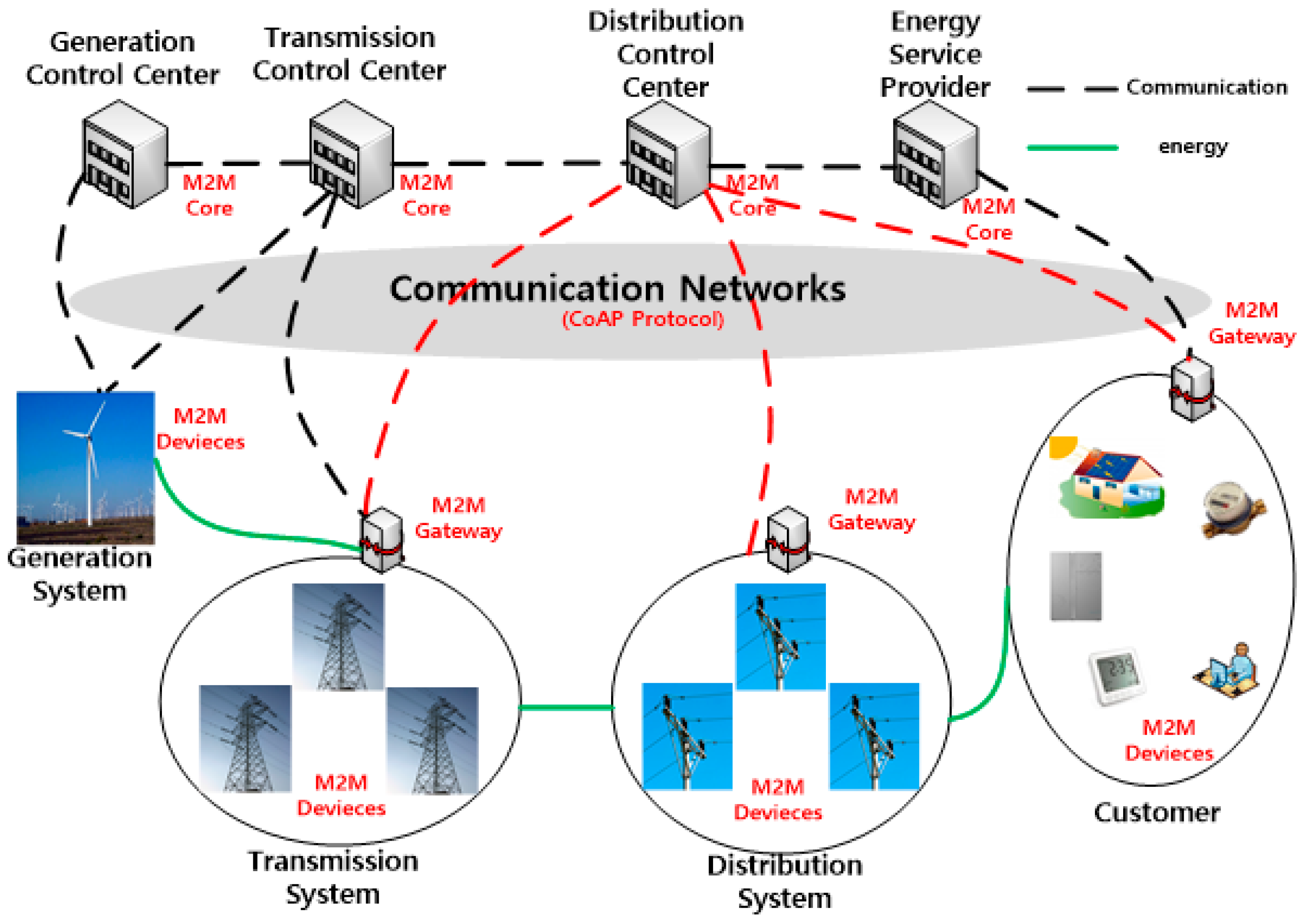
:1. Introduction
2. Power IT Protocols
2.1. IEC 61850
- -
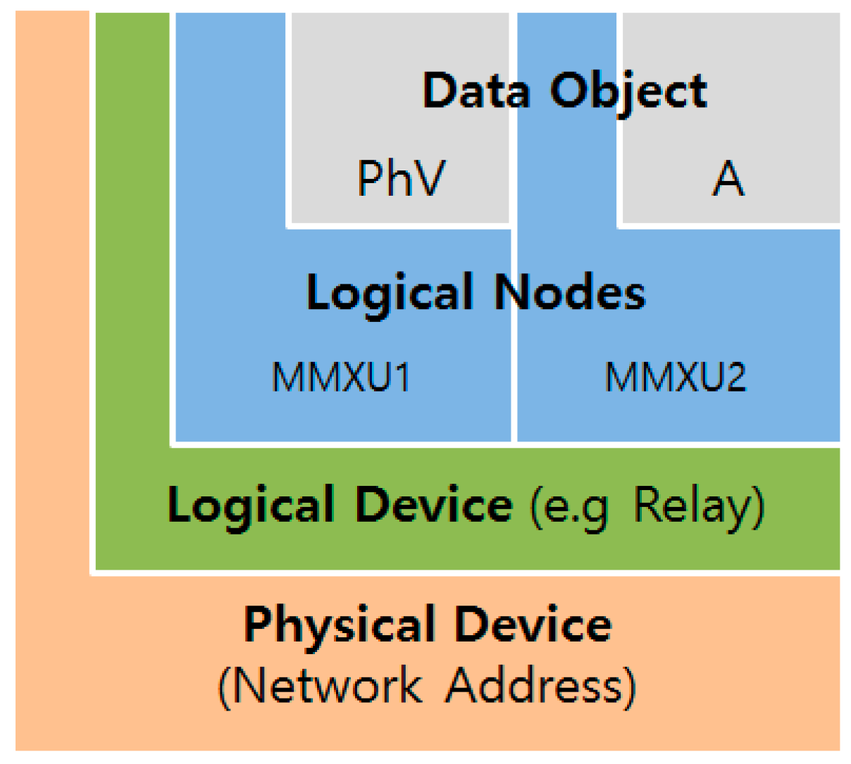
- Data Modeling: Primary process objects as well as protection and control functionality in the substation are modeled into different standard logical nodes, which can be grouped under different logical devices. There are logical nodes for data/functions related to the logical node zero (LLN0) and logical node for physical device (LPHD).
- -
- Reporting Schemes: There are various reporting schemes buffered report control block and unbuffered report control block (BRCB & URCB) for reporting data from the server through a server-client relationship, which can be triggered based on pre-defined trigger conditions.
- -
- Fast Transfer of events: Generic substation events (GSEs) facilitate fast transfer of event data within a peer-to-peer communication mode. These substation events are again subdivided into GOOSE and GSSE.
- -
- Setting Groups: The setting group control blocks (SGCBs) handle the setting groups so that the user can switch to any active group according to his or her requirements.
- -
- Sampled Data Transfer: Schemes are also defined to handle transfer of sampled values using sampled value control blocks (SVCBs).
- -
- Commands: Various command types are also supported by the IEC 61850. These include direct and select before operate (SBO) commands with normal and enhanced securities.
- -
- Data Storage: A substation configuration language (SCL) is defined for complete storage of a substation’s configured data in a specific format.
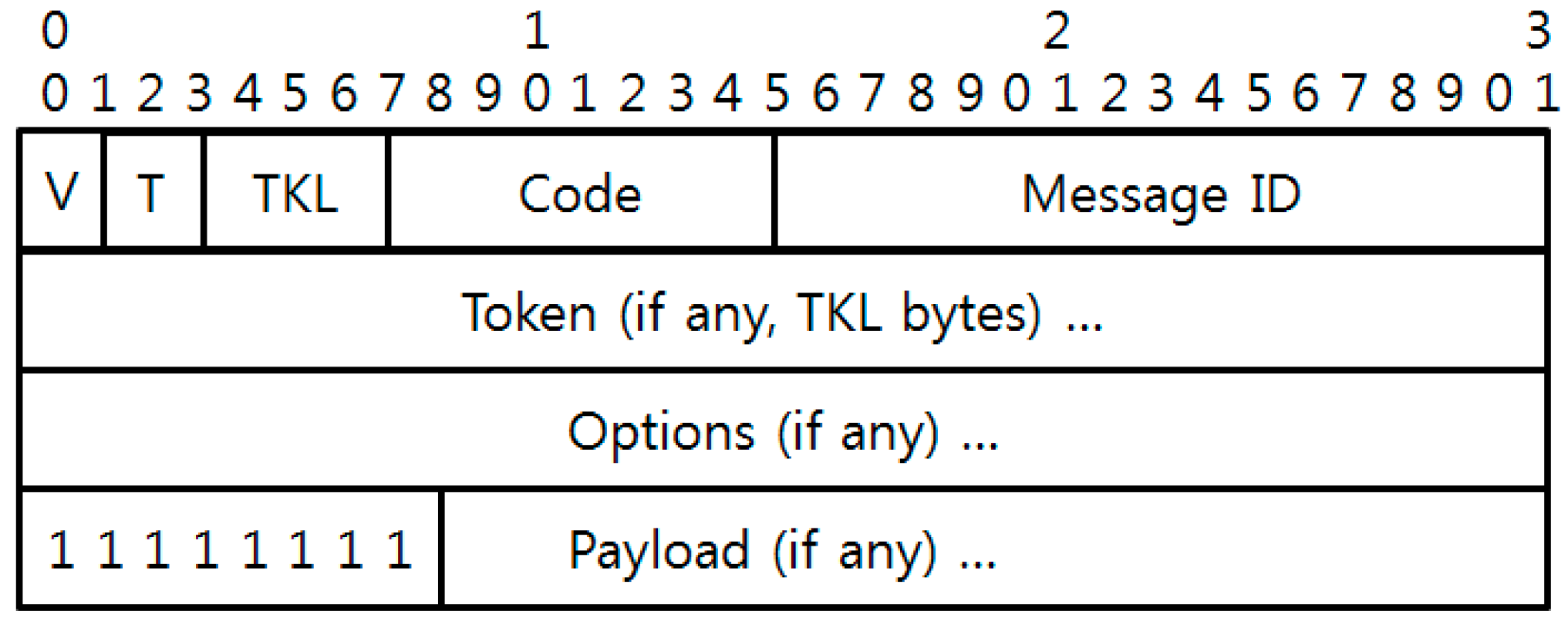
2.2. CoAP-Based on REST
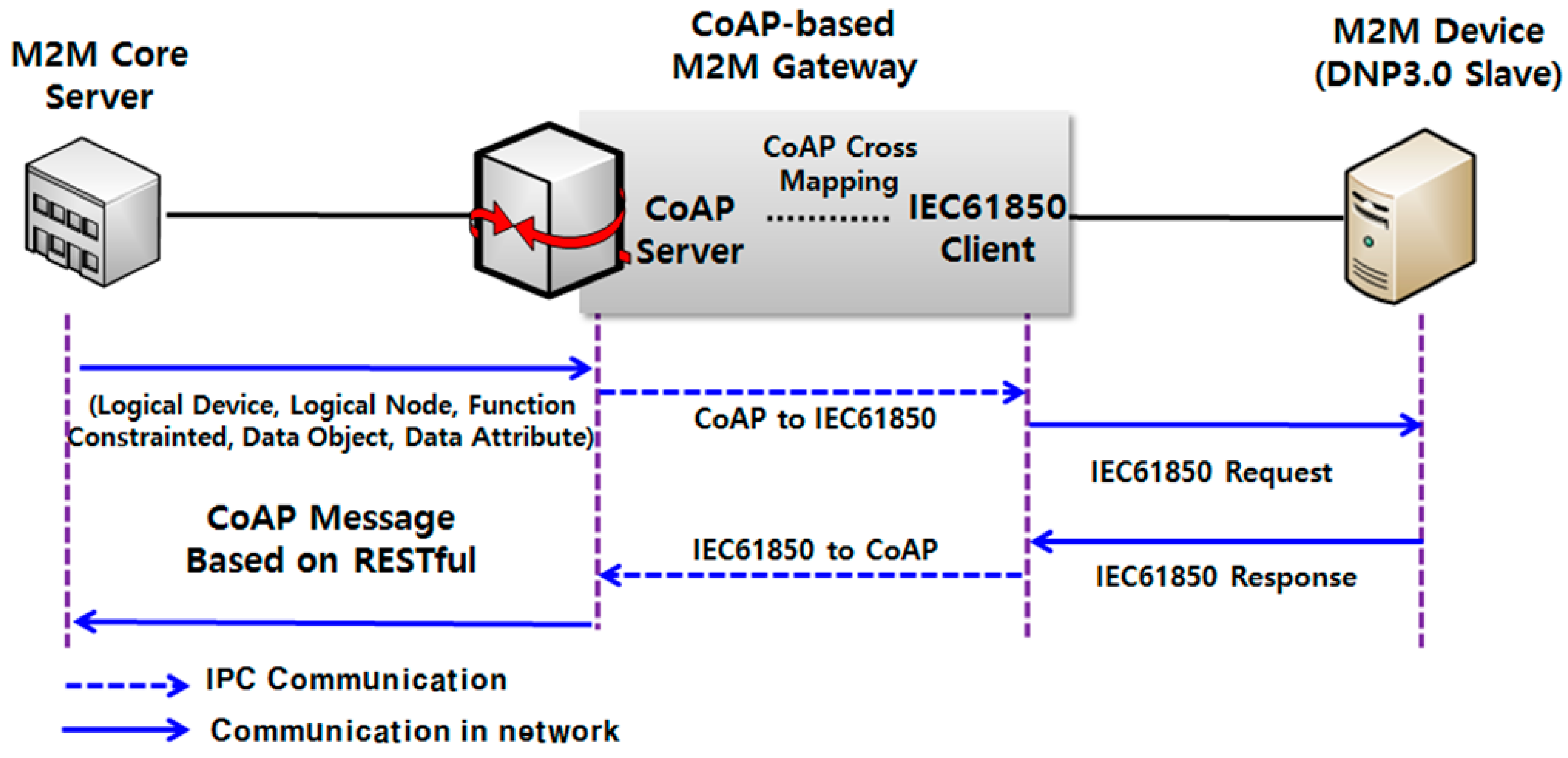
3. CoAP-Based M2M Gateway
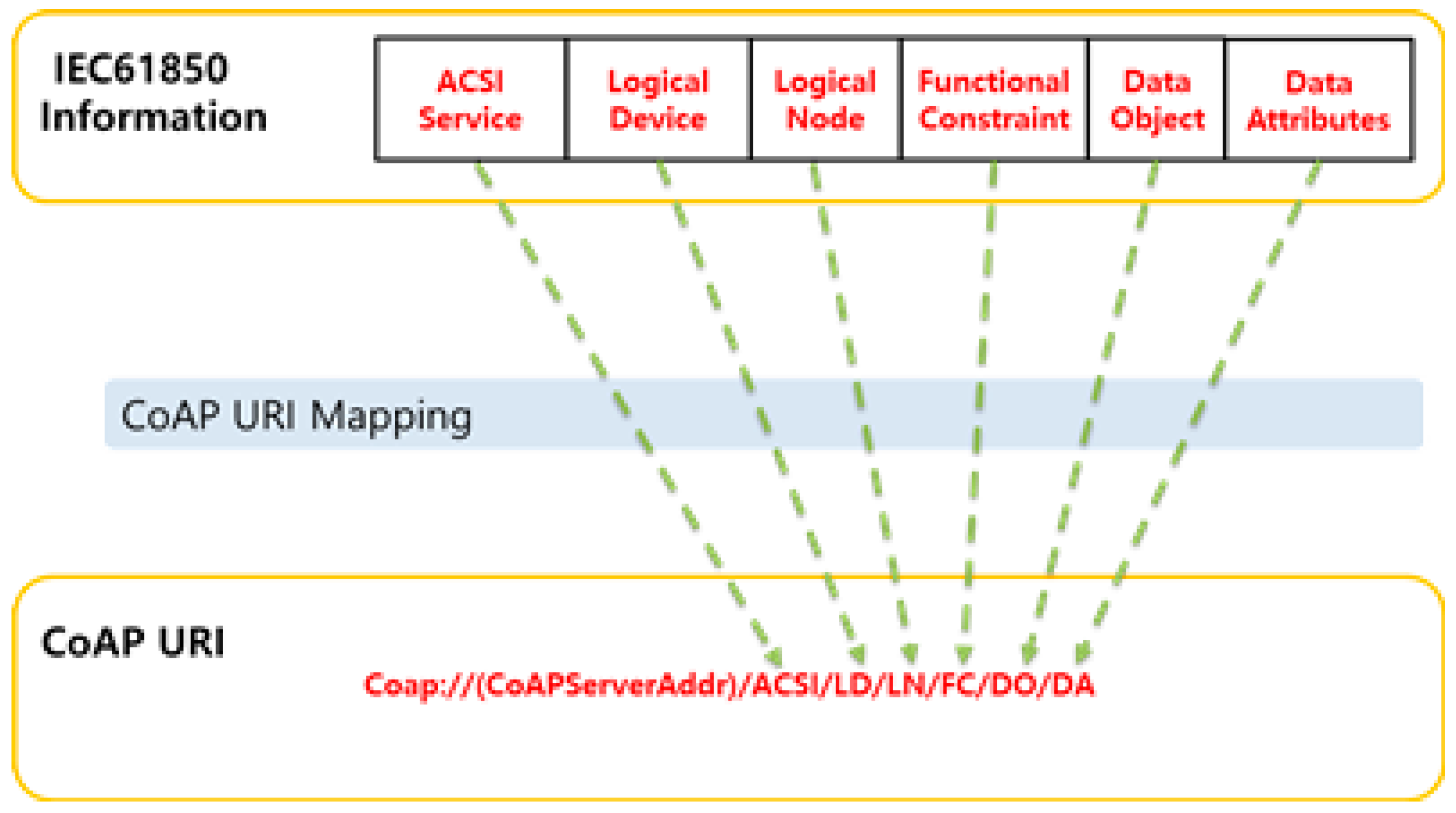
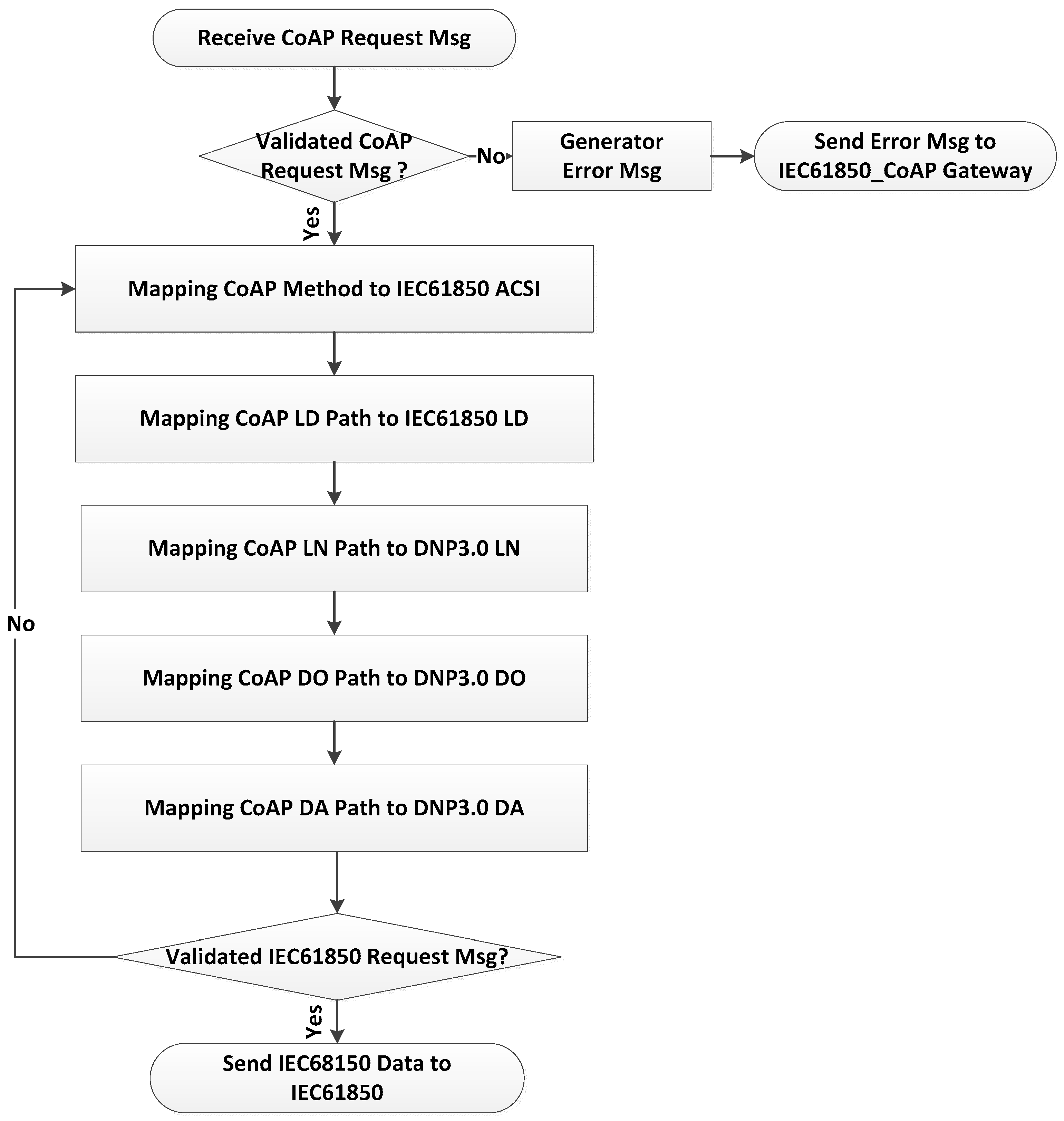
3.1. CoAP Mapping Method for IEC 61850
- coap://(CoAPServerAddr)/ACSIService/LogicalDevice/LogicalNode/FunctionalConstrint/
- DataObejct/DataAttribute
- coap://((CoAPServerAddr)/01/GEDevice/XCBR1/ST/Pos/stVal
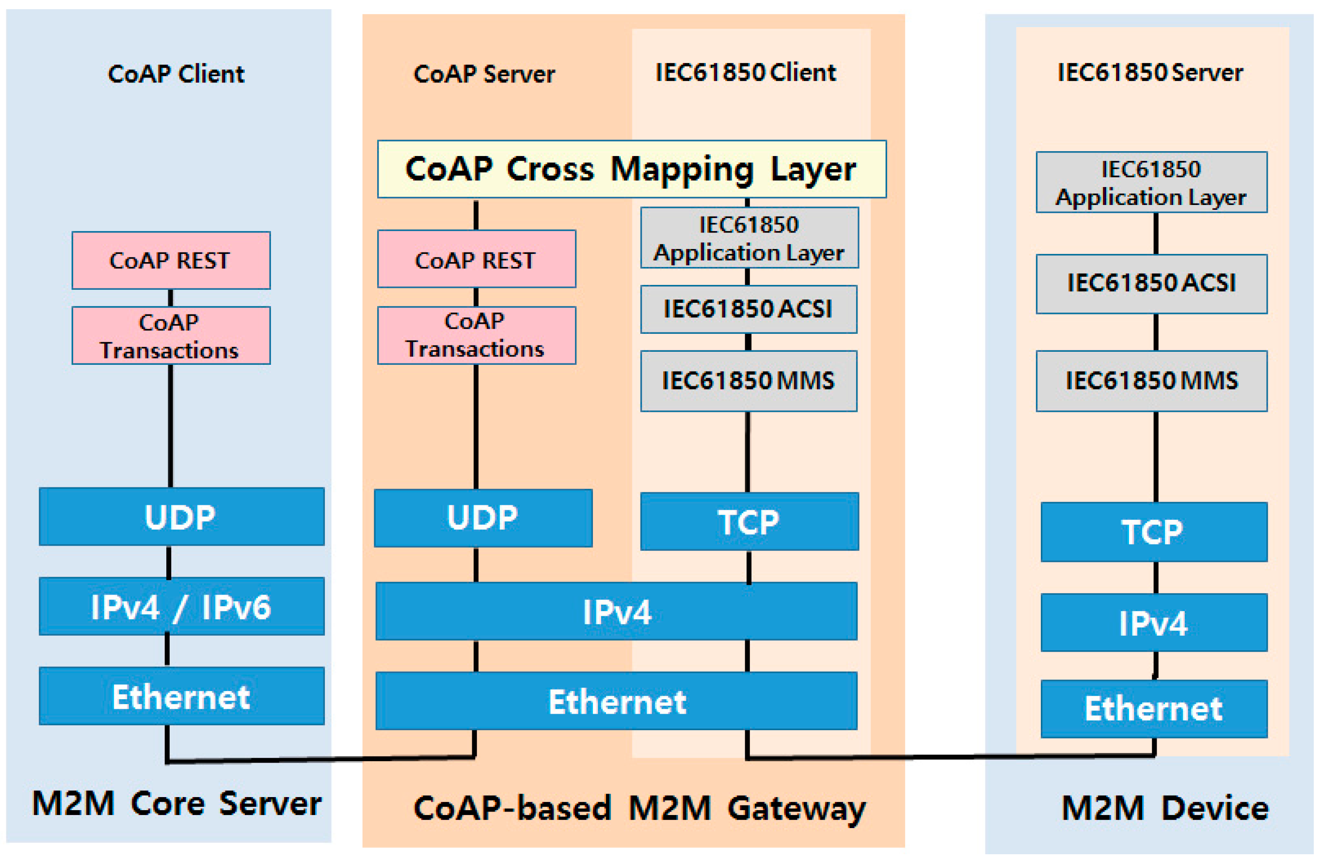
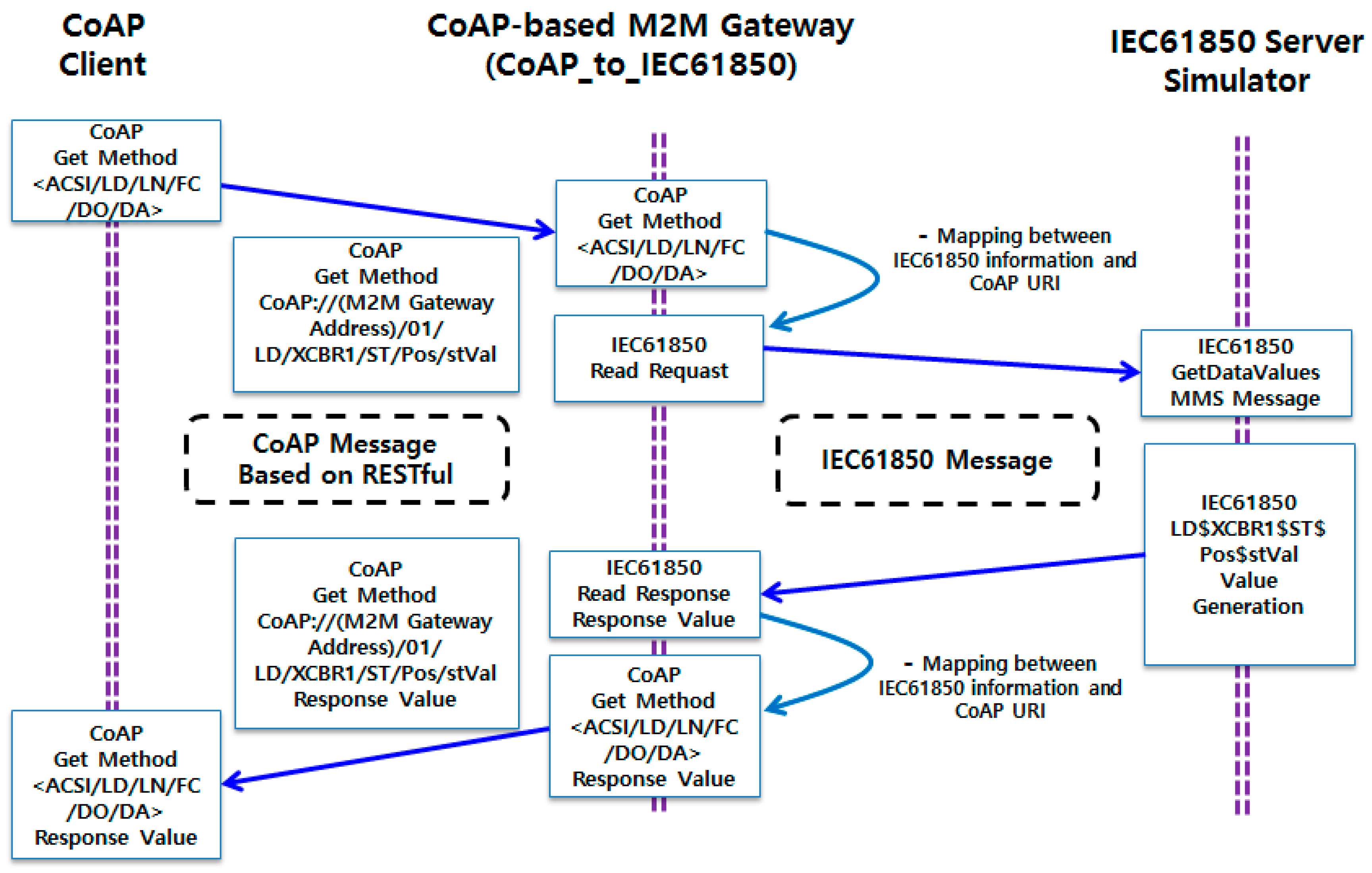
3.2. CoAP-Based M2M Gateway Implementation
- CoAP Method: GET
- CoAP URI: 01/LD/XCBR1/ST/Pos/stVal
- -
- ACSI Service: GetDataValues
- -
- Logical Device: LD
- -
- Logical Node: XCBR1
- -
- Functional Constraint: ST
- -
- Data Object: Pos
- -
- Data Attribute: stVal
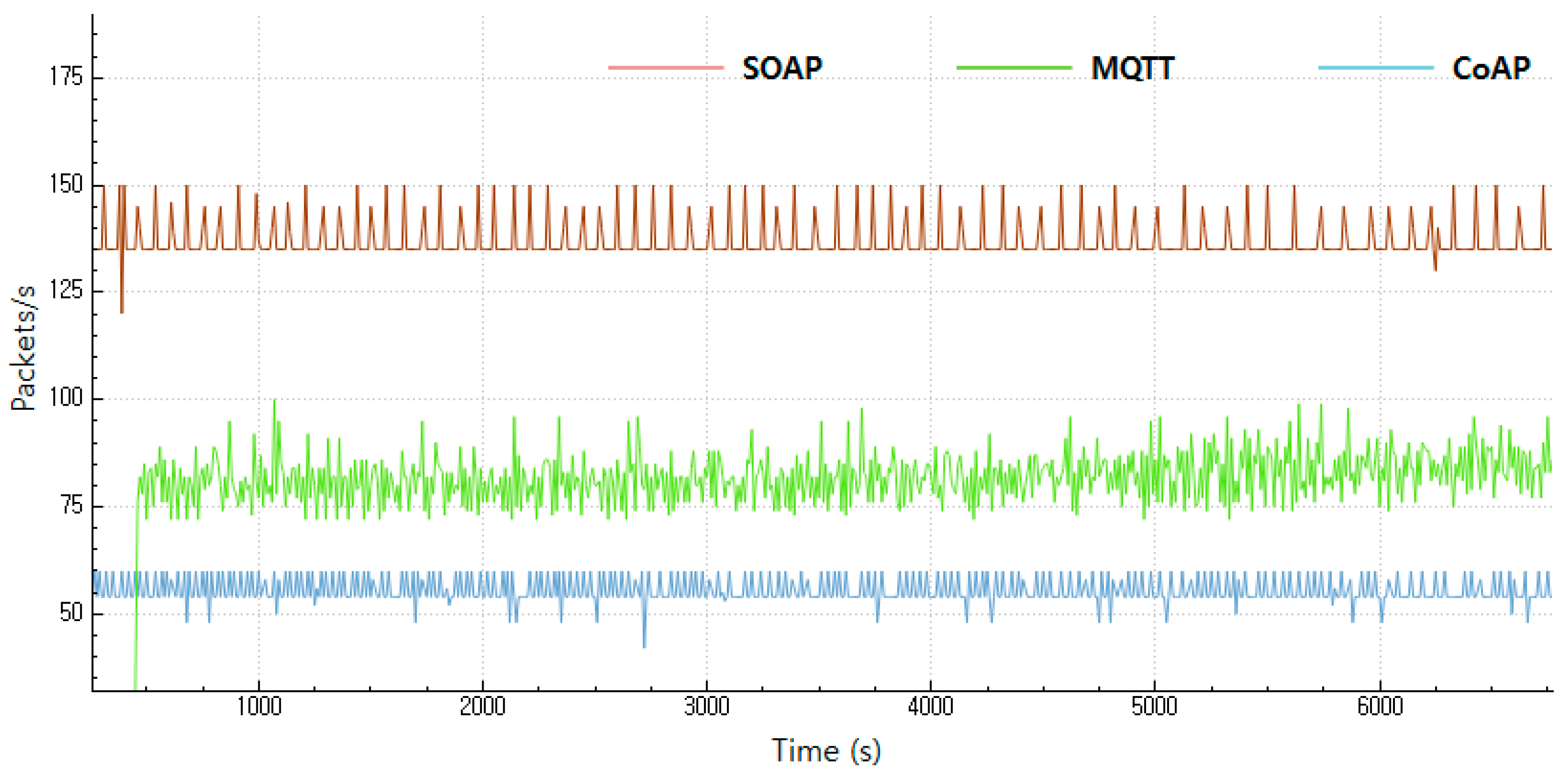
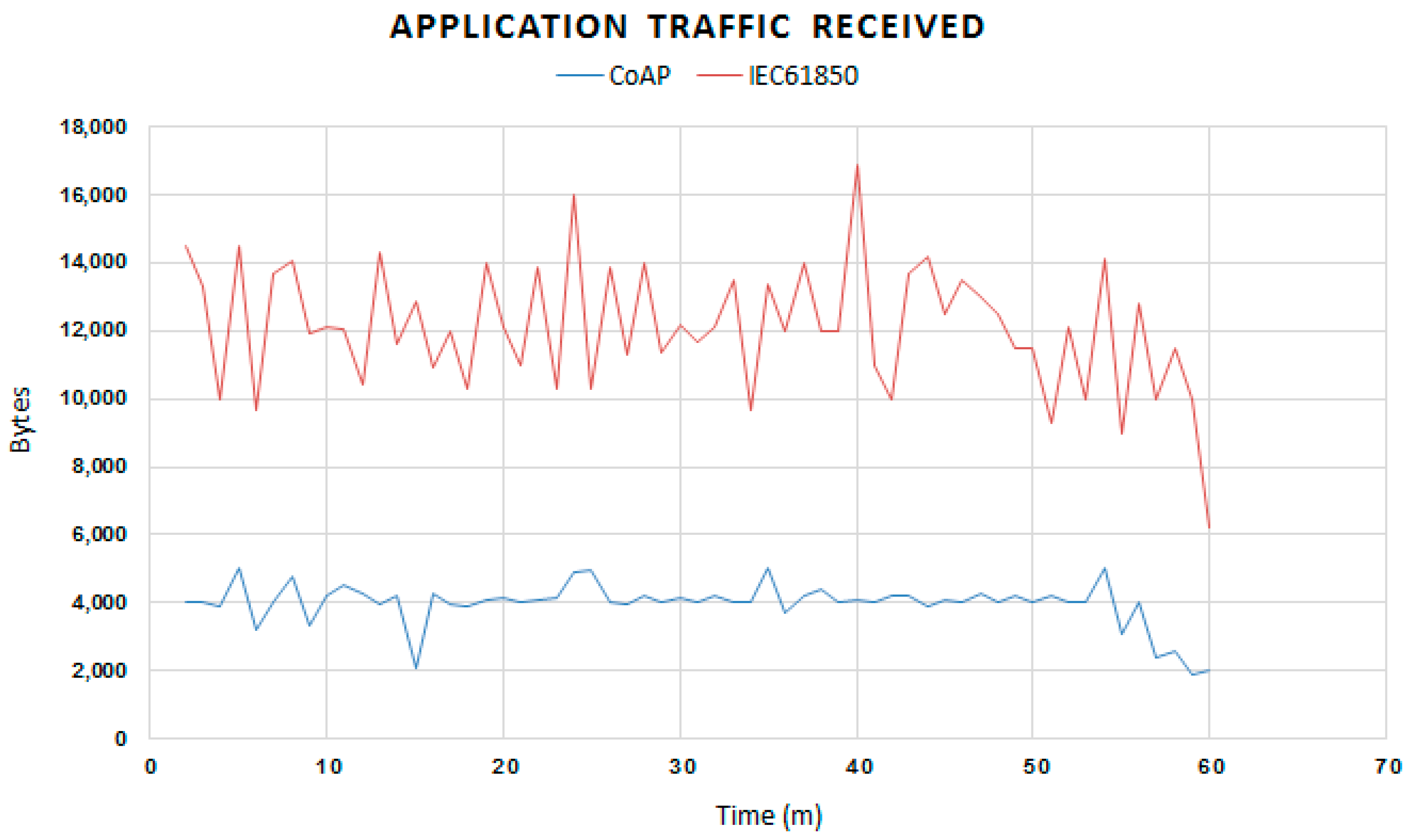
4. Experimental Analysis
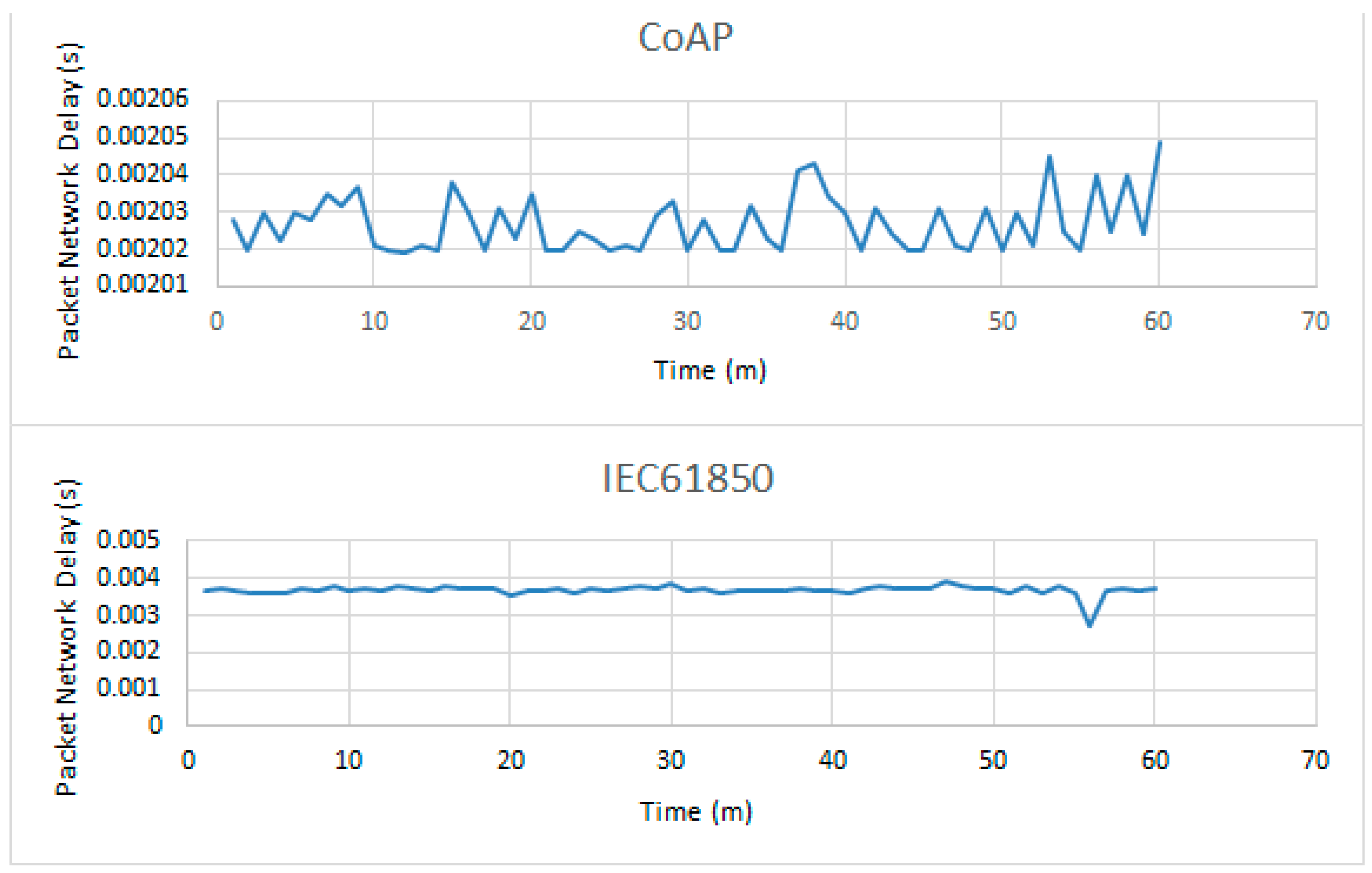
4.1. Performance Evaluation
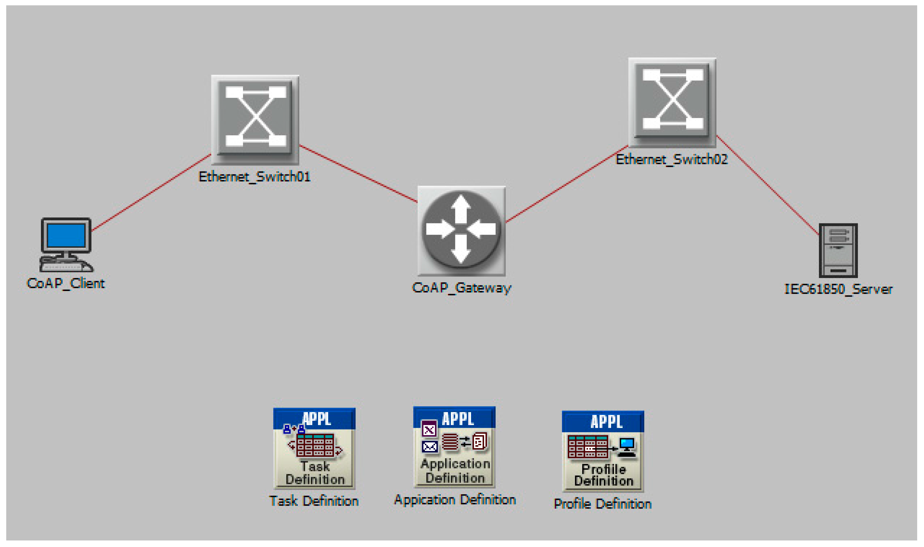
4.2. OPNET Simulator
5. Conclusions
Acknowledgments
Author Contributions
Conflicts of Interest
References
- Clark, G.; Reynders, D. Practical Modern SCADA Protocols; Butterworth-Heinemann: Oxford, UK, 2004. [Google Scholar]
- ITU Internet Reports 2005: The Internet of Things. Available online: http://www.itu.int/internetofthings (accessed on 17 November 2005).
- European Telecommunications Standards Institute. Machine-to-Machine Communications (M2M): Functional Architecture; ETSI 102 690; European Telecommunications Standards Institute: Sophia Antipolis, France, 2011. [Google Scholar]
- Lu, G.; Seed, D.; Starsinic, M.; Wang, C.; Ressell, P. Enabling Smart Grid with ETSI M2M Standards. In Proceedings of the IEEE Wireless Communications and Networking Conference Workshops 2012, Paris, France, 1 April 2012; pp. 148–153.
- IEEE Standard for Electric Power Systems Communications–Distributed Network Protocol (DNP3); IEEE 1815; IEEE: New York, NY, USA, 2010.
- Shin, I.J.; Eom, D.S.; Song, B.K. CoAP-based M2M gateway for distribution automation system using DNP3.0 in smart grid environment. In Proceedings of the 2015 IEEE International Conference on Smart Grid Communications, Miami, FL, USA, 2–5 November 2015.
- Anders, B.P.; Einar, B.H.; Peter, B.A. Facilitating a generic communication interface to distributed energy resources. In Proceedings of the 2010 First IEEE International Conference on Smart Grid Communications, Gaithersburg, MD, USA, 4–6 October 2010.
- CoRE Working Group. Constrained Application Protocol Draft-Ietf-Core-Coap-18; IETF: Fremont, CA, USA, 2013. [Google Scholar]
- International Electrotechnical Commission (IEC). Communication Networks and Systems for Power Utility Automation–Part 7-2: Compatible Logical Node Classes and Data Object Classes; International Standard IEC61850-7-1; IEC: Chicago, IL, USA, 2010. [Google Scholar]
- International Electrotechnical Commission (IEC). Communication Networks and Systems for Power Utility Automation–Part 7-1: Compatible Logical Node Classes and Data Object Classes; International Standard IEC61850-7-2; IEC: Chicago, IL, USA, 2010. [Google Scholar]
- International Electrotechnical Commission (IEC). Communication Networks and Systems for Power Utility Automation–Part 7-4: Compatible Logical Node Classes and Data Object Classes; International Standard IEC61850-7-4; IEC: Chicago, IL, USA, 2010. [Google Scholar]
- International Electrotechnical Commission (IEC). Communication Networks and Systems for Power Utility Automation–Part 6: Configuration Description Language for Communication in Electrical Substations; International Standard IEC61850-6; IEC: Chicago, IL, USA, 2009. [Google Scholar]
- International Electrotechnical Commission (IEC). Communication Networks and Systems for Power Utility Automation–Part 8-1: Specific Communication Service Mapping (SCSM)—Mappings to MMS (ISO 9506-1 and ISO 9506-2) and to ISO/IEC 8802-3; International Standard IEC61850-8-1; IEC: Chicago, IL, USA, 2011. [Google Scholar]
- Fielding, R.T. Abstract of the Dissertation: Architectural Styles and the Design of Network-Based Software Architectures; University of California: Irvine, CA, USA, 2000. [Google Scholar]
- Fielding, R.T.; Taylor, R.N. Principled design of the modern web architecture. ACM Trans. Internet Technol. 2002, 2, 115–150. [Google Scholar] [CrossRef]
- Mitra, N. Simple Object Access Protocol (SOAP) 1.2. Available online: http://www.w3.org/TR/2003/REC-soap12-part1- 20030624/ 2003 (accessed on 18 September 2016).
- Bary, T.; Paoli, J.; Speberg-McQueen, C.M. Extensible Markup Language (XML) 1.0. Available online: http://www.w3.org/TR/REC-xml (accessed on 18 September 2016).


| Method | ACSI Service | ACSI Mapping Code |
|---|---|---|
| GET | GetDataValues | 01 |
| GET | GetAllDataValues | 02 |
| GET | GetDataList | 03 |
| GET | GetDataDefinition | 04 |
| GET | GetBRCBValues | 05 |
| GET | GetURCBValues | 06 |
| PUT | SetDataValues | 10 |
| SCL (Substation Configuration Language) Example of IEC 61850 Model | CoAP URI Registration Example of Source Code | |
|---|---|---|
| <FCDA ldInst = “MEAS” lnClass = “MMXU” prefix = “SAG” lnInst = “1” doName = “PhV.phsA” fc = “MX” /> | 1 | register = coap_resource_init((unsigned char *) “01/MEAS/MMXU1/MX/Phv/phsA”, 22, 0); |
| 2 | coap_register_handler(register,COAP_REQUEST_GET, hnd_get_service); |
| Area | Packet Length (Min.–Max.) | Packet Length Average | Percent |
|---|---|---|---|
| CoAP | 62–74 | 67 | 100% |
| IEC61850 | 40–79 | 68 | 0.56% |
| 80–129 | 114 | 99.44% |
© 2017 by the authors. Licensee MDPI, Basel, Switzerland. This article is an open access article distributed under the terms and conditions of the Creative Commons Attribution (CC BY) license ( http://creativecommons.org/licenses/by/4.0/).
Share and Cite
Shin, I.-J.; Song, B.-K.; Eom, D.-S. International Electronical Committee (IEC) 61850 Mapping with Constrained Application Protocol (CoAP) in Smart Grids Based European Telecommunications Standard Institute Machine-to-Machine (M2M) Environment. Energies 2017, 10, 393. https://doi.org/10.3390/en10030393
Shin I-J, Song B-K, Eom D-S. International Electronical Committee (IEC) 61850 Mapping with Constrained Application Protocol (CoAP) in Smart Grids Based European Telecommunications Standard Institute Machine-to-Machine (M2M) Environment. Energies. 2017; 10(3):393. https://doi.org/10.3390/en10030393
Chicago/Turabian StyleShin, In-Jae, Byung-Kwen Song, and Doo-Seop Eom. 2017. "International Electronical Committee (IEC) 61850 Mapping with Constrained Application Protocol (CoAP) in Smart Grids Based European Telecommunications Standard Institute Machine-to-Machine (M2M) Environment" Energies 10, no. 3: 393. https://doi.org/10.3390/en10030393