Article

Modeling and Analysis of Double Stator Slotted Rotor Permanent Magnet Generator

by
Suhairi Rizuan Che Ahmad
1,2,3,
Raja Nor Firdaus Kashfi Raja Othman
1,2,*,
Md Nazri Othman
1,2,
Nor Aishah Md Zuki
1,2,
Fairul Azhar Abdul Shukor
1,2,
Siti Zulaika Mat Isa
1,2,
Zulkifilie Ibrahim
1 and
Chockalingam Aravind Vaithilingam
4
1
Faculty of Electrical Engineering, Universiti Teknikal Malaysia Melaka (UTeM), Hang Tuah Jaya, Durian Tunggal, 76100 Melaka, Malaysia
2
Electrical Machine Design, Power Electronics and Drives Research Group, CeRIA, UTeM, Hang Tuah Jaya, Durian Tunggal, 76100 Melaka, Malaysia
3
Universiti Kuala Lumpur-British Malaysian Institute (UNIKL-BMI), Gombak, 53100 Selangor, Malaysia
4
School of Engineering, Taylor’s University Malaysia, Subang Jaya, 47500 Selangor, Malaysia
*
Author to whom correspondence should be addressed.
Energies 2017, 10(3), 411; https://doi.org/10.3390/en10030411
Submission received: 31 January 2017 / Revised: 13 March 2017 / Accepted: 16 March 2017 / Published: 21 March 2017

Abstract

:
This paper discusses the modeling and analysis of three phase double stator slotted rotor permanent magnet generator (DSSR-PMG). The use of double stator topology through the double magnetic circuit helps to maximize the usage of flux linkage in the yoke structure of the single stator topology. The analytical computation is done using Permeance Analysis Method (PAM). Finite Element Analysis (FEA) is used for numerical verifications and to verify the design structure a prototype laboratory is performed. The analysis is done with various loading conditions to derive the electromagnetic torque, output power and efficiency for the proposed structure. The analytical, numerical and experimental results from the analysis are found to be in good agreement. The maximum power developed by this generator at rated speed of 2000 rpm is of 1 kW with the operational efficiency of 75%. A rectifier bridge circuit is used to make the generated voltage a storage capable constant voltage to make it suitable for mobile applications (such as Direct Current DC generator). The proposed generator structure is highly recommended for applications such as micro-hydro and small renewable plants.

1. Introduction

The demand for global energy is increasing rapidly and hence efficient generators are required to optimize the energy generation capability. More recently, Permanent Magnet Generator (PMG) due to higher power density is becoming the most common energy-generating unit replacing the conventional generators [1,2,3,4]. The authors earlier in their work used the high power output through the double stator topology achieved with the reduction of the leakage flux produced for conventional machine. PMG with double stator topology is attempted for practical applications for energy conversions including electric vehicle [5,6,7,8,9], agricultural applications [10] and wind power generation [11,12]. However, the structure in double stator design is complex and requires extensive design analysis.
In this paper, a modeling of Double Stator Slotted Rotor Permanent Magnet Generator (DSSR-PMG) using Permeance Analysis Method (PAM) is proposed. The proposed slotted rotor double stator topology with small air gap increases the output power of DSSR-PMG [13]. Ferromagnetic material is used for slotted rotor in order to maximize the flux produced by the permanent magnet and coil, through reduction of leakage flux. The modeling approach uses high accuracy FEA simulation (Ansys-Maxwell 16®) that gives an approximation on microscopic scale to validate results [14,15]. A 1-kW prototype of DSSR-PMG is designed, fabricated and tested experimentally. Non-overlapping series concentrated winding is used for both inner and outer stators to reduce the losses. With shorter end-windings, lower harmonic magnetomotive force MMF, reduced eddy current losses in the PM and higher slot fill ratio [16,17,18] is highly feasible. The performance characteristics of DSSR-PMG are evaluated through the improved generation capability.
This paper is organized as follows: Section 1 discusses about the introduction and the intended application of the research. Section 2 describes the basic structure, parameters and machine modeling using the Permeance Analysis Method (PAM). Section 3 describes the experimental setup of the fabricated prototype. Section 4 presents the validation of the model based on FEA simulation, analytical and measurement result including output characteristics of prototype model. Section 5 derives the conclusions of the paper.

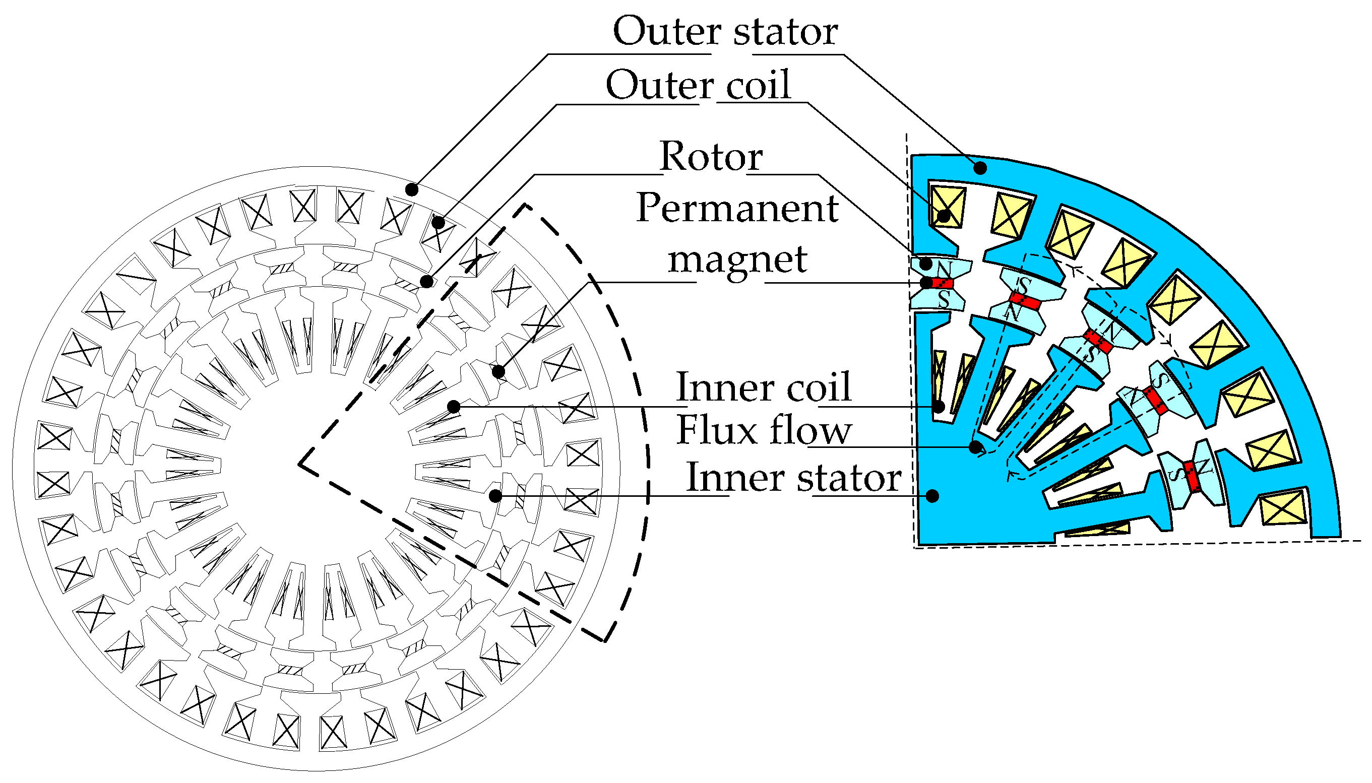
2. Basic Structure and Model Parameter of DSSR-PMG

A three-phase 18 slots 20 poles arrangement slot type generator with series connected concentrated winding for outer and inner stator is designed through the fractional numbers of slots per pole. This way the cogging torque could be kept lower. Other methods include skewing the stator or rotor slot and permanent magnet shaping [19]. The design consists of outer stator, inner stator, rotor, permanent magnet, outer coil and inner coil. The stators and rotor are made from non-oriented silicon steel (M250-35A) and Neodymium Boron Iron (NdFeB 42) for permanent magnet as shown in Figure 1 with radial flux direction at the air gap. The coil is made from copper with 0.6 mm diameter and the detail parameters of DSSRPMG model is shown in Table 1.

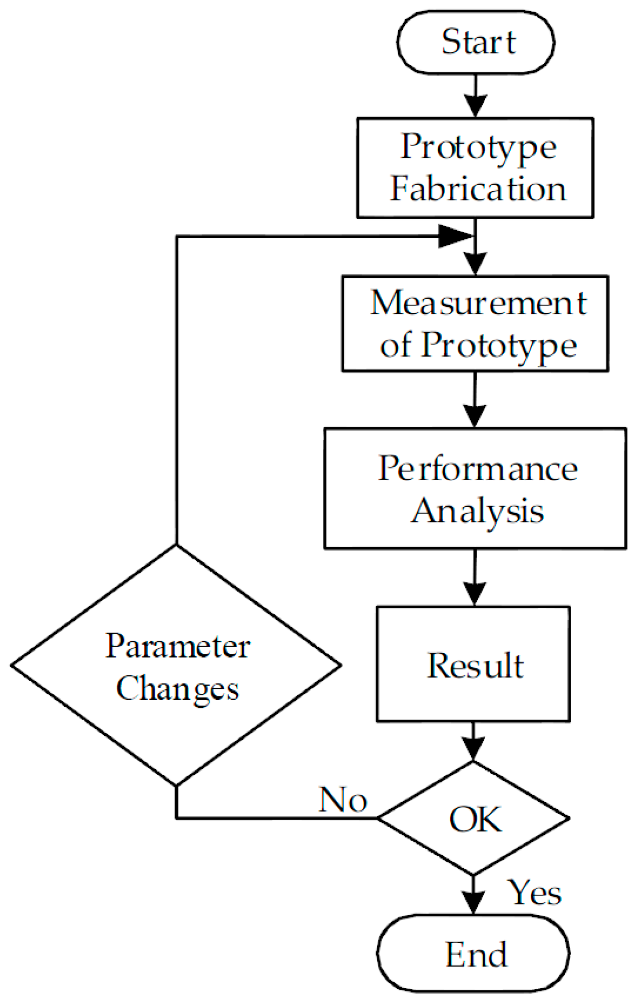
2.1. Flowchart of Research Design

The design method used in this research includes the analytical calculation using the Permeance Analysis Method (PAM) and the numerical calculation using the Finite Element Analysis (FEA). In FEA, Ansys Maxwell is used as a tool to simulate the magnetix flux, cogging torque and inductances, while, in PAM, the magnetic flux is calculated using magnetic circuit and mathemathical modeling based on the flux flows in the stator, rotor and the air gaps.
The FEA starts with the developing the structure modeling of the generators. The flow chart of FEA modeling is shown in Figure 2a. The process includes development of mesh of the DSSR-PMG. This mesh is used to provide the suitable quantity and location of elements in the developed model. A detail mesh gives an accurate result but requires high specification of computer and high time consumption. In the magnetic analysis process, several iterative calculations are done and the the output such as flux flow path, magnetic flux density and cogging torque are captured. In Figure 2b, the PAM analysis begins with the magnetic circuit modeling of DSS-PMG based on the shape of flux linkage at the inner stator, outer stator, inner air gap, outer air gap and rotor. The simplified equivalent magnetic circuit is developed and derivation of magnetic flux is calculated using mathemathical modeling approach. The performance analysis of the DSSR-PMG, such as torque, mechanical power, output power, and efficiency, are compared for validation of the results.

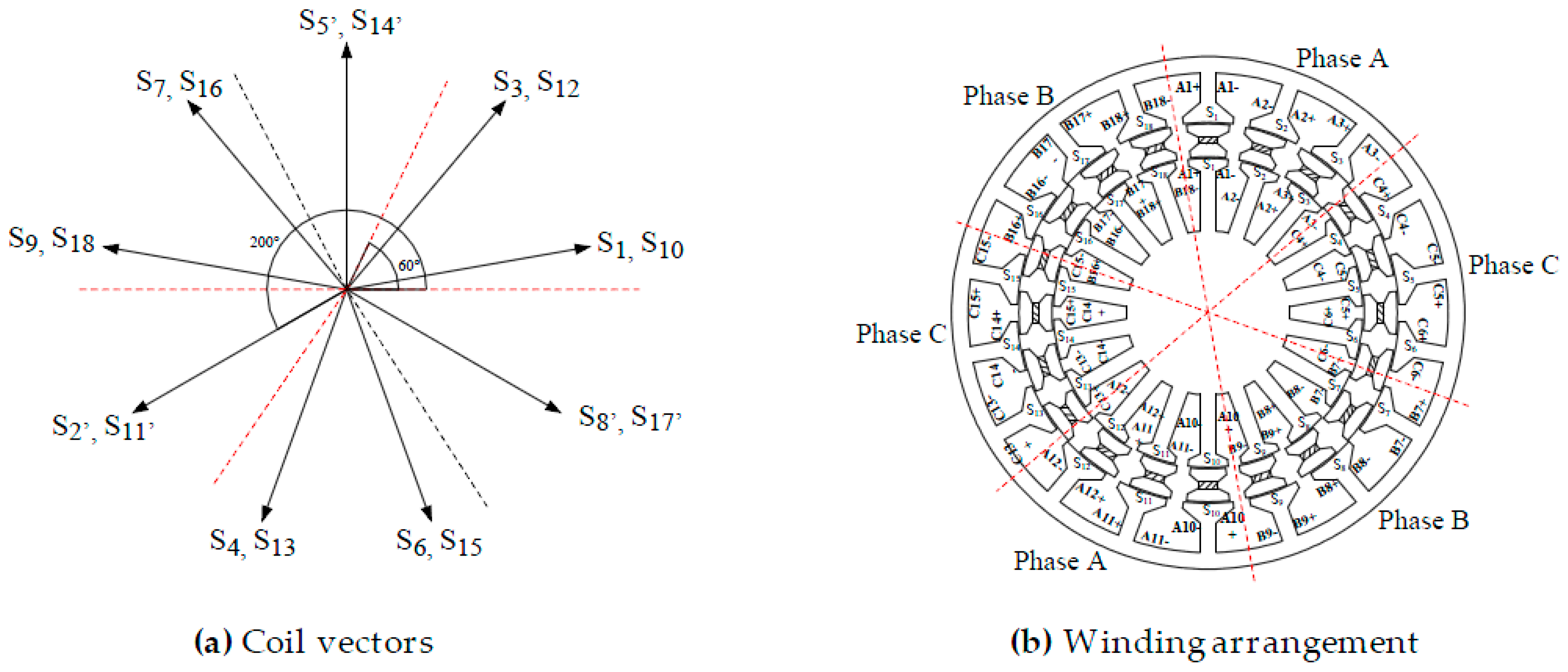
2.2. Coil Vectors and Winding Arrangement

In this paper, the Star Of Slots (SOS) method is used to find the winding layout for DSSR-PMG. The coil vector arrangement is defined by the electrical degree of the electromotive force (EMF) induced in the coil side of each slot. Figure 3 shows the coil vectors and winding arrangement of DSSR-PMG where S means slot number inside the generator. Each phase has four coils connected in series. The phasor inside in the same sector belongs to the same phase as in Figure 3a. For phase A, the vector numbers with S1, S2′, S3, S10, S11′, and S12 are in one sector. Since S2′ and S11′ are in opposite direction, they are denoted with apostrophes, which means the coil in negative polarity. The same process is applied to phase B (S7, S8′, S9, S16, S17', and S18) and phase C (S4, S5′, S6, S13, S14′, and S15). Each phase encompasses six slots with four slots in positive and the other two with negative polarity. The winding arrangement for the inner and outer stator of DSSR-PMG is shown in Figure 3b. The details phase and coil arrangements for DSSR-PMG are listed in Table 2.

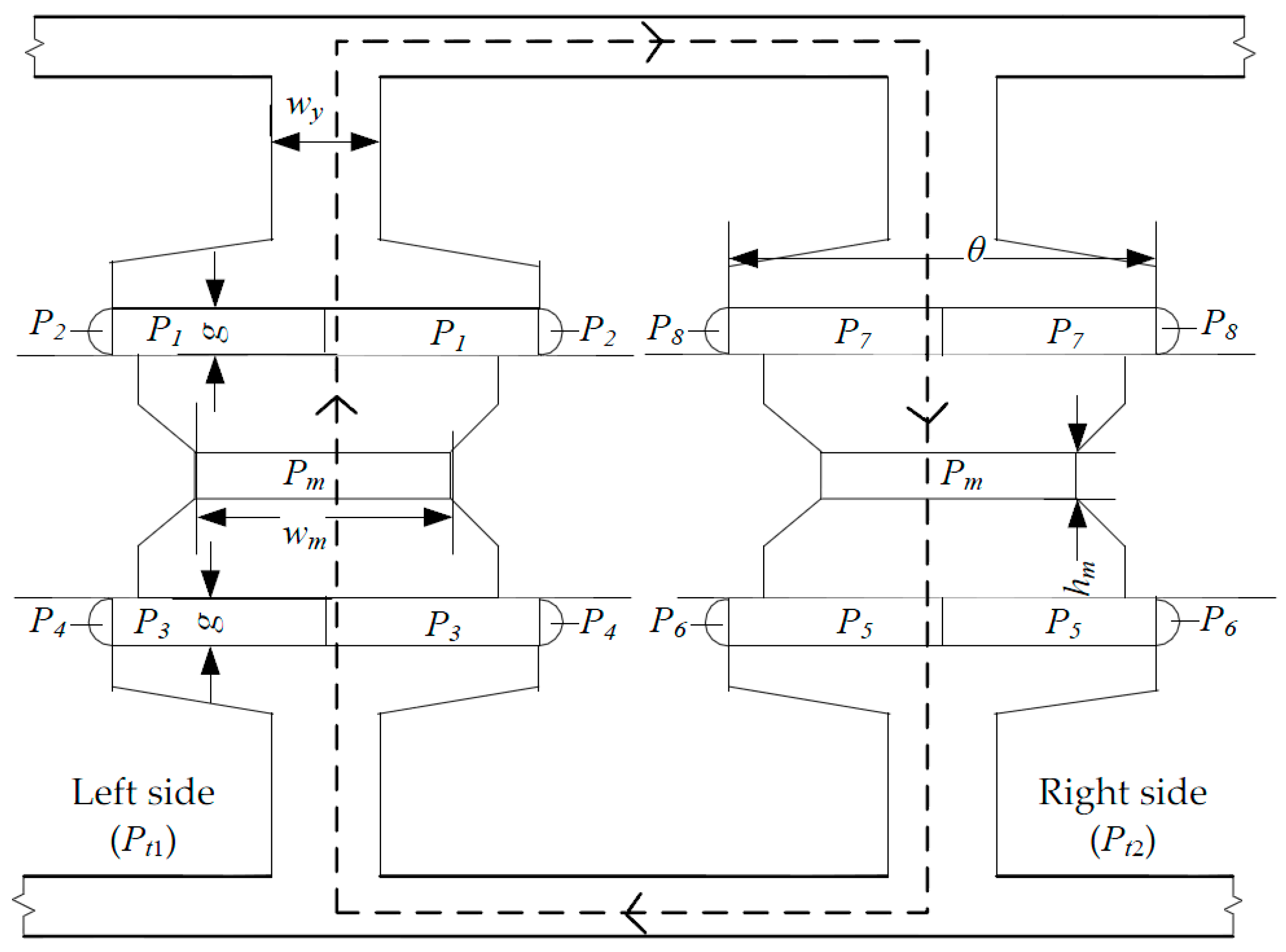
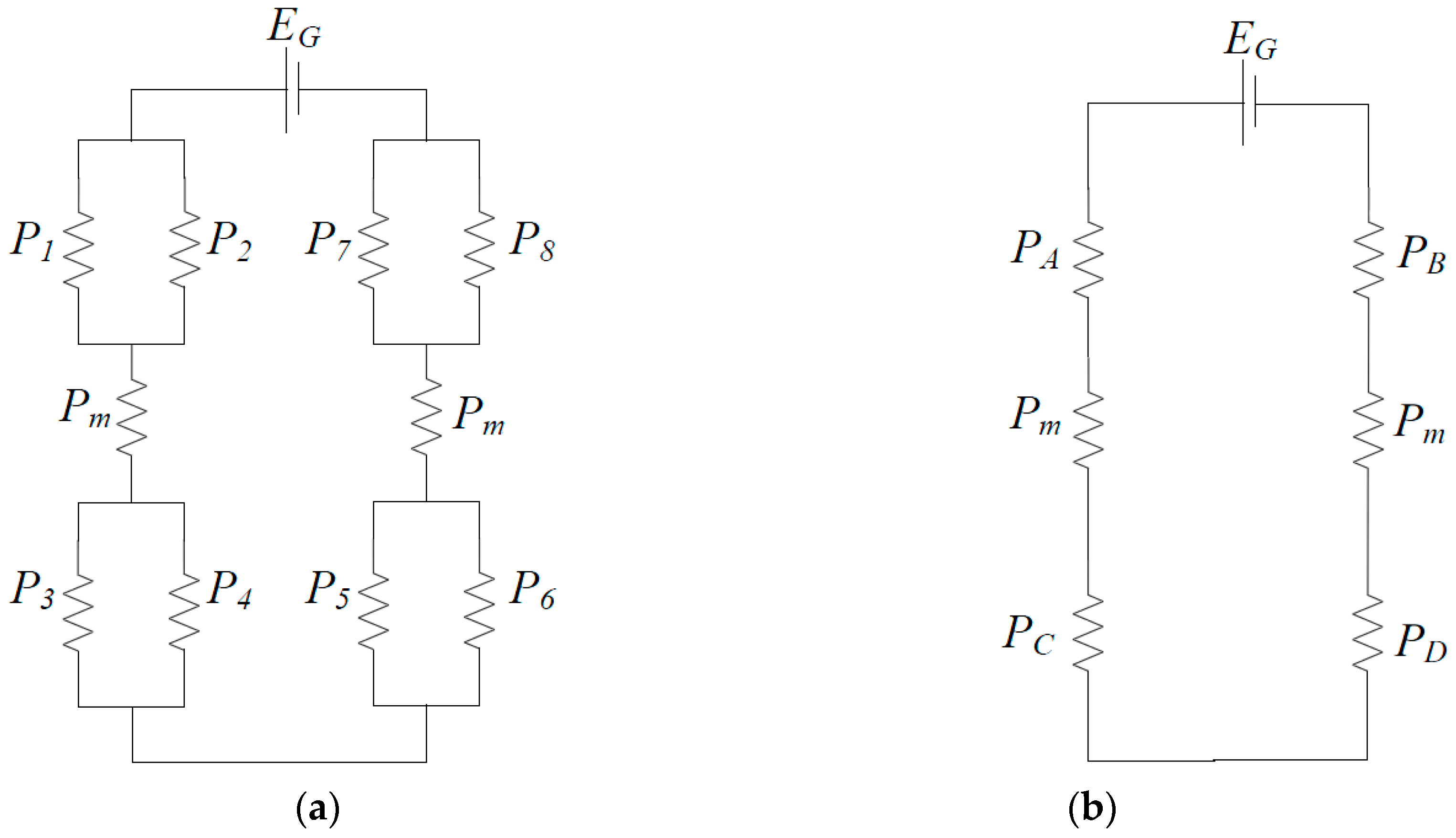
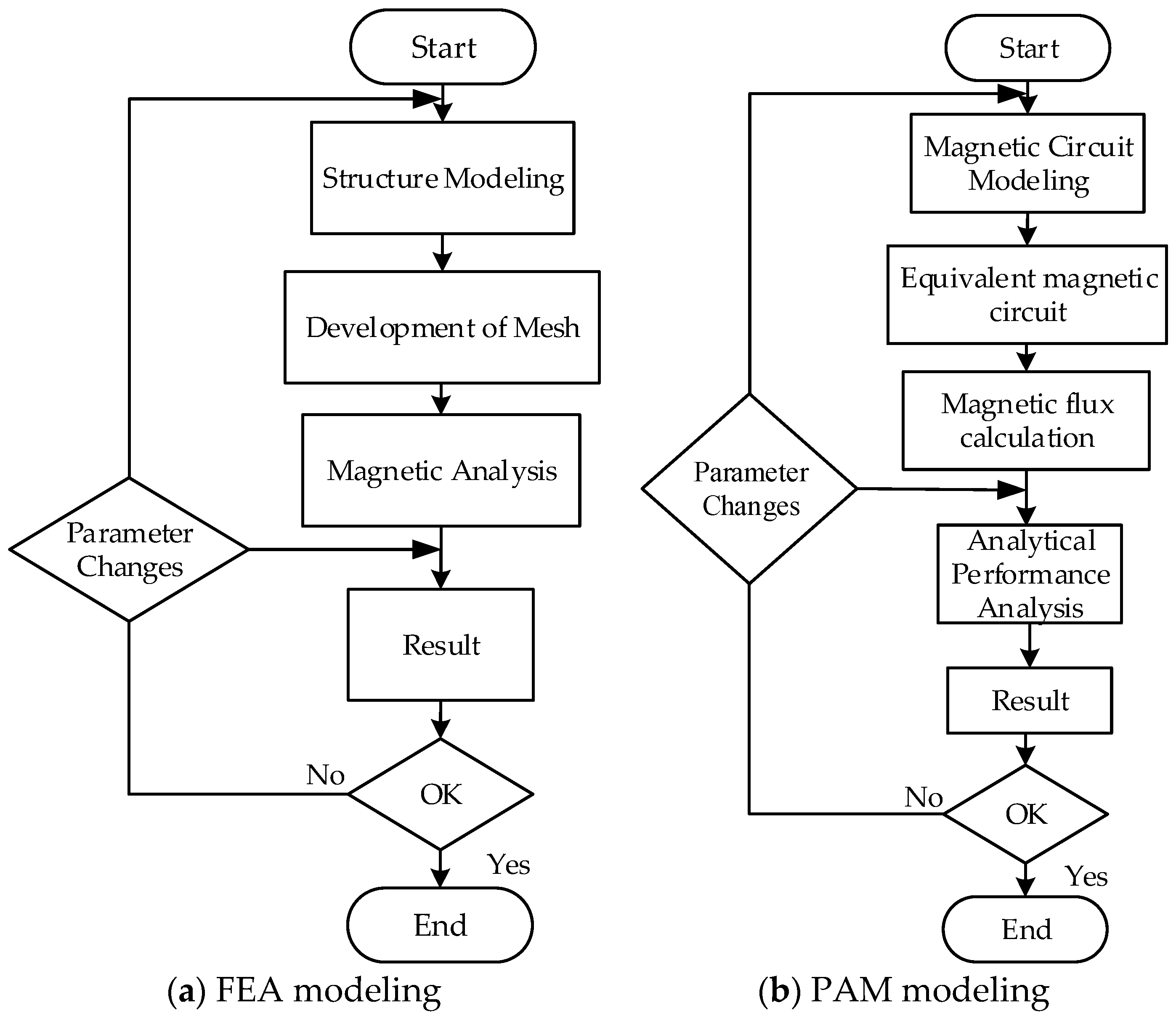
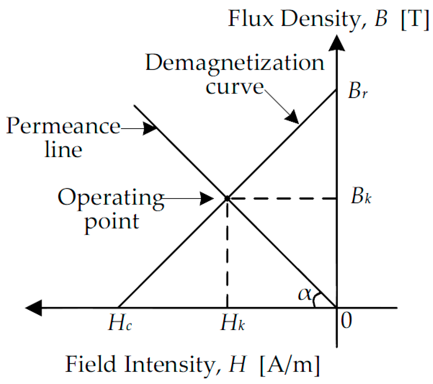
2.3. Permeance Analysis Method (PAM)

Figure 4a shows the flux lines and flux density of three phase DSSR-PMG with phase A is energized at 2000 rpm under no-load conditions. The flux travels through outer and inner stator, rotor core, and permanent magnet. The highest flux density at the stator yoke is observed at 0.9 T as shown in Figure 4b.
The magnetic flux produced by the permanent magnet (PM) in DSSR-PMG is calculated using permeance computations. Figure 5 shows the basic electrical equivalent circuit of the permanent magnet generator with the generated voltage (EG), resistive load (RL), and internal resistance of coil winding (Rc), where Lc is the self inductance of the generator.
In DSSR-PMG, a dual flux linkage generated at the inner stator and outer stator air gap. The relation between flux linkage and back electromotive force (EMF) is as shown in Equation (1).
E m f = N d ϕ d t
where N is the number of turns, ϕ is the rate of change of magnetic flux and t is the rate of change of time.
Figure 6 shows the flux flow from the N pole PM through the outer air gap into the stator yoke teeth and travels along the stator yoke and also along the stator core. Then the flux flow through adjacent stator yoke to outer air gap and through rotor core the S pole of PM to the inner stator air gap then return to adjacent slot through the inner stator core and yoke. Then, the flux flows to the inner air gap and rotor core.
Since the permeance shape for both sides of the slot is the same, the calculation of permeance is considered in the left side only. The total permeance is calculated by combination of left and right side where, μο is the permeability factor in the air in (H/m), μ is the permeability in the material in (H/m), g is the air gap in inner and outer stator (m), wm is the width of the PM in (m), hm is the height of the PM slot in (m), θ is the angle of the stator in (rad), l is the depth of the DSSR-PMG in (m), rro is the radius of outer rotor in (m), rri is the radius of inner rotor in (m), r is the radius at the air gap in (m), l is the deep length of the DSSR-PMG in (m), and wy is the width of the stator yoke in (m). All of the calculations focus on one magnetic circuit only since the others are identical. The permeance calculation based on the shape of flux linkage as depicted in Figure 6. The permeance method is used to obtain analytical results using mathematical modeling.
The magnetic equivalent circuit for three phase DSSR-PMG is shown in Figure 7. There are nine part of permeance numbered P1, P2, P3, P4, P5, P6, P7, P8 and Pm, as shown in Figure 7a. P1, P2, P7, and P8 are the permeance at the outer air gap; P3, P4, P5, and P6, are the permean at the inner air gap; and Pm is the permeance at the magnet. All the permeances in the outer and inner air gap are in parallel and series with the permeance of magnet. The simplified magnetic for this permeance is shown in Figure 7b and labeled as PA, PB, PC, PD and Pm. P1, P3, P5, and P7 are used as in Equation (2). P2, P4, P6, and P8 are used as in Equation (3).
P 1 = μ o l θ ln [ 1 + g r r o ]   ( H )
P 2 = 1.63 μ o [ r + g 4 ]   ( H )
The permeance calculation on the left side is shown in Equations (4)–(12)
P A = P 1 + P 2   ( H )
P A = μ o l θ ln [ 1 + g r r o ] + 1.63 μ o [ r + g 4 ]   ( H )
P B = P 3 + P 4   ( H )
P 3 = μ o l θ ln [ 1 + g r r i ]   ( H )
P 4 = 1.63 μ o [ r + g 4 ]   ( H )
P B = μ o l θ ln [ 1 + g r r i ] + 1.63 μ o [ r + g 4 ]   ( H )
P M = μ w m l 2 h m   ( H )
1 P t 1 = 1 P A + 1 P B + 1 P M   ( H )
Substitute Equations (6), (11) and (13) into Equation (14):
P t 1 = P B P M + P A P M + P A P B P A P B P M   ( H )
Since Pt1 = Pt2, the permeance total is the sum of permeance as in Equations (13) and (14).
P T = P t 1 + P t 2   ( H )
P T = 2 [ μ o μ w m l 3 θ 2 + 1.63 μ o 2 μ w m l 2 θ [ r + g 4 ] { [ ln ( 1 + g r r i ) ] + [ ln ( 1 + g r r o ) ] } + 2.6569 μ o 2 μ w m l [ r + g 4 ] [ ln ( 1 + g r r o ) ] [ ln ( 1 + g r r i ) ] μ o μ w m l 2 θ { [ ln ( 1 + g r r o ) ] + [ ln ( 1 + g r r i ) ] } + 3.26 μ o μ w m l [ r + g 4 ] [ ln ( 1 + g r r o ) ] [ ln ( 1 + g r r i ) ] + 2 h m μ o 2 l 2 θ 2 + 3.26 h m μ o 2 l θ [ r + g 4 ] { [ ln ( 1 + g r r i ) ] + [ ln ( 1 + g r r o ) ] } + 5.3138 h m μ o 2 [ r + g 4 ] [ ln ( 1 + g r r o ) ] [ ln ( 1 + g r r i ) ] ]   ( H )
The operating point of the permanent magnet is calculated by solving the intersection of two straight lines which is B-H curve of PM and permeance line is shown in Figure 8.
α is the angle of the permeance line slope, Hc is the coercive force in (kA/m), Br is a remanent flux density in (T), Bk is a magnetic flux density of the permanent magnet at operating point in (T), and Hk is the magnetic field intensity of the permanent magnet at operating point in (A/m). The angle, α, of the permeance line slope is as in Equation (15). The magnetic flux density, Bk, and magnetic field intensity are calculated as per Equations (15)–(19).
tan α = P T H c h m B r w m l
B k = ( tan α ) H k   ( T )
B k = [ P T H c h m B r w m l ] H k   ( T )
H k = B r B r H c + [ P T H c h m B r w m l ]   ( A / m )
B k = P T H c 2 h m B r B r 2 w m l + P T H c h m   ( T )
where ϕ M is the maximum flux at the magnet in (Wb), and N is the total number of turns in inner and outer stator as shown in Equations (20)–(23). Am is the area of the magnet in (m2), e is the electrical degree in (°) and p is number of pole of DSSR-PMG. Therefore, the total flux in the PMG is calculated using Equation (23).
ϕ M = N B k A m   ( W b )
ϕ M = [ N ] [ P T H c 2 h m B r B r 2 w m l + P T H c h m ] [ h m l ]   ( W b )
ϕ M = N P T H c 2 h m 2 B r l B r 2 w m l + P T H c h m   ( W b )
ϕ = ϕ M sin ω θ + 2 e p   ( W b )

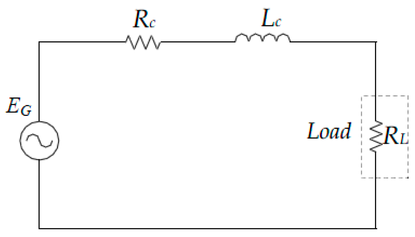
2.4. Output Power Estimation

In order to estimate the performance of the DSSR-PMG with the prime mover torque, input power, mechanical input power and efficiency, FEA-Analytical method is used. Here, the losses calculation such as the core, hysteresis and eddy current losses have been considered by FEA. The input power, which is the mechanical input power from the prime mover that rotates the DSSR-PMG, is calculated using Equation (24).
P m = 2 π × T × n 60   ( W )
where Pm is the mechanical input power by the machine in (W) that acts as a prime mover, T is the torque (Nm), and n is the rotational speed in (rpm). The measured output power of the generator is measured at the load using Equation (25), whereas V is the DC output voltage (Vdc) and Idc is the DC output current (A) that is rectified from the rectifier circuit. The efficiency, η, is calculated as shown in Equation (26).
P o = V d c × I d c   ( W )
η = P m P o × 100   ( % )

3. Experimental Testing

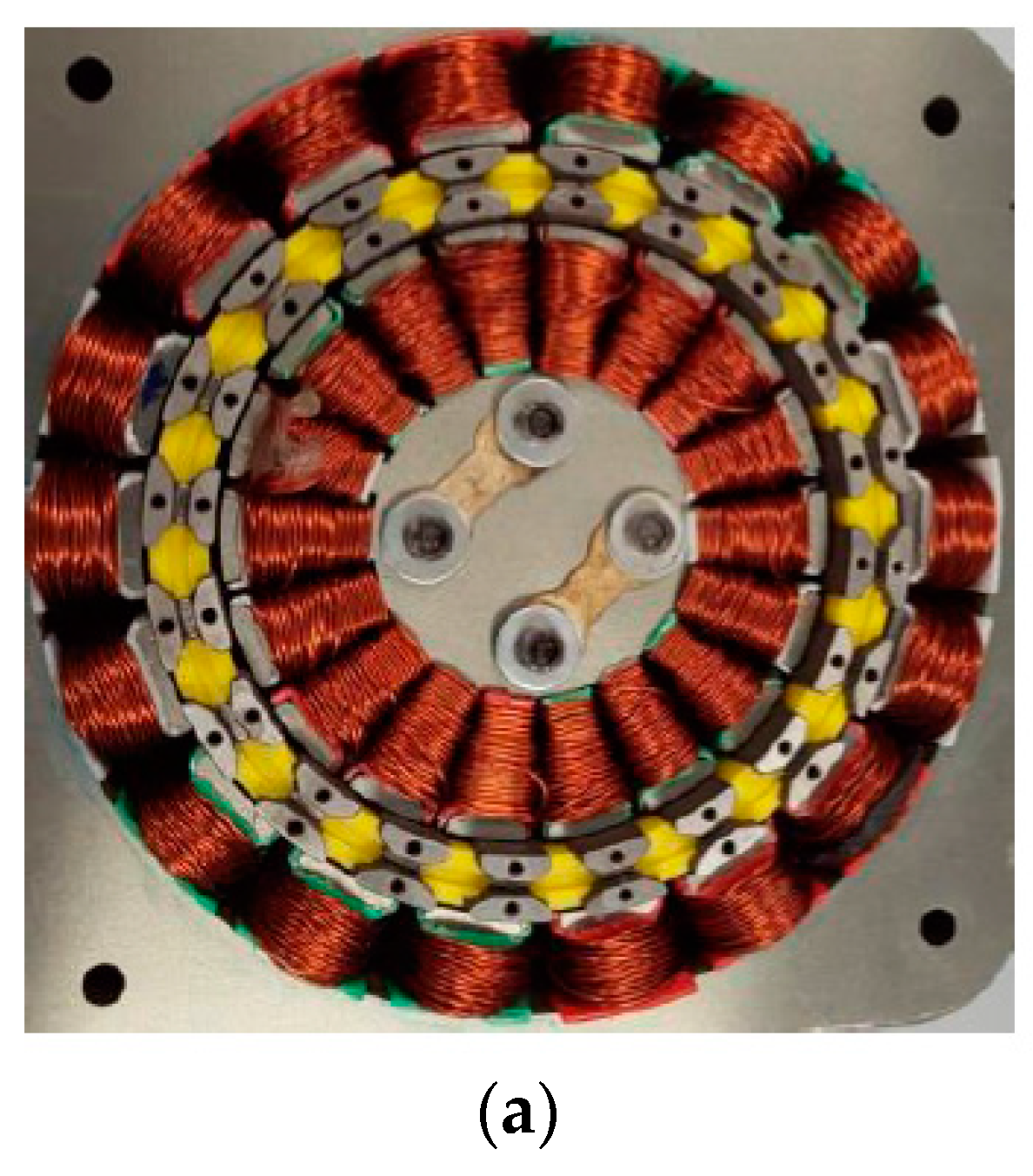
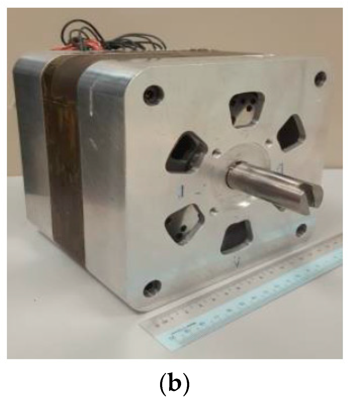
3.1. Prototype Fabrication

The flowchart of experimental process is shown in Figure 9. A prototype of DSSR-PMG is fabricated to test its performance under laboratory conditions. The cross-sectional structure with the coil windings, rotor, permanent magnets and fillers of the fabricated machine is shown in Figure 10a, and the fully assembled fabricated machine is shown in Figure 10b. The rotor, outer stator and inner stator are made from non-oriented silicon steel with the total depth of the stator is 52.5 mm. The air gaps between rotor and stators are 0.5 mm. Ferromagnetic material (SUS 403) is used for slotted rotor material. The non-arc permanent magnets (NdFeB 42) with dimension of 6 mm × 2 mm × 52.5 mm are embedded between the pole shoes. The casing is made from solid aluminum since it is lightweight and the shaft from non-ferromagnetic material. The results of current, voltage and torque are analyzed; however, the change in speed and load of DSSR-PMG during experimental process requires the measurement prototype to be repeated.

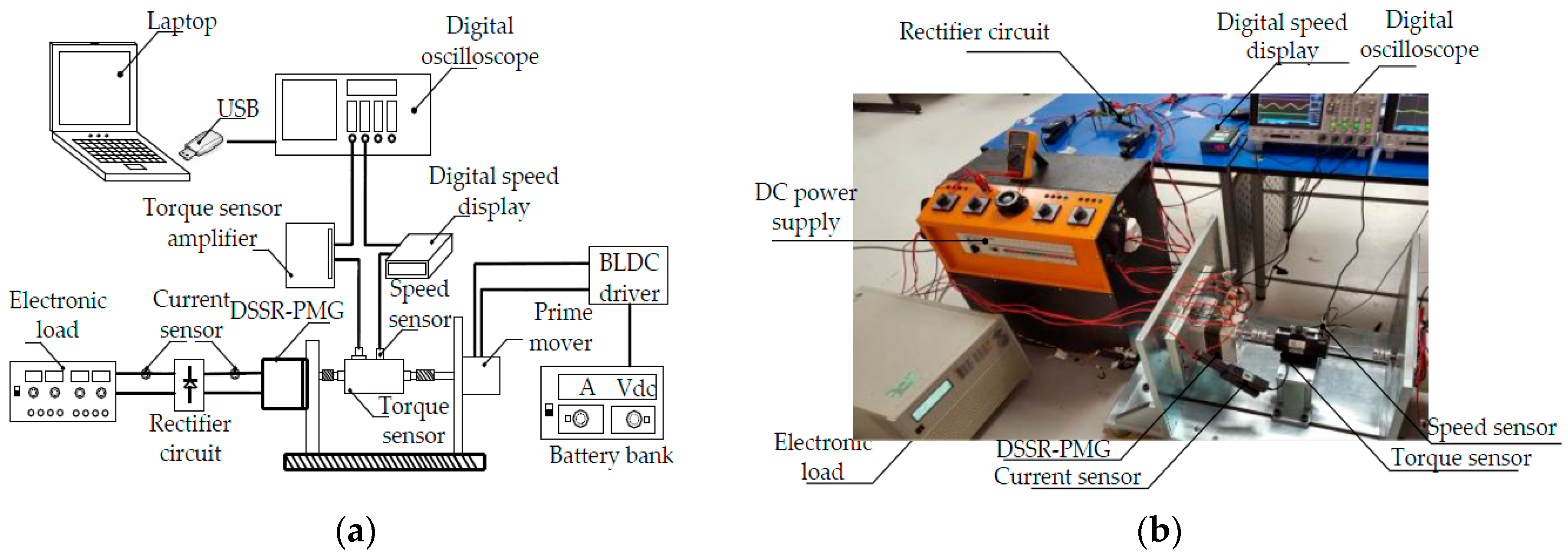
3.2. Experimental Test Bench

The measurement setup of DSSR-PMG is shown in the block diagram and experimental setup is shown in Figure 11a,b, respectively. The fabricated DSSR-PMG is attached to the jig with instrumentation system for measurements and derived by the 3-kW High Power Brushless DC motor to act as a prime mover. The speed of the prime mover is controlled by throttle that comes with the vector control driver. As the prime mover rotates, the output voltage and current through the loads is recorded using the digital oscilloscope. The generated output voltage and the current from the DSSR-PMG are rectified by the full bridge rectifier circuit before being connected to the 4.5 kW AC/DC Electronic load. The load is varied from 10 Ω to 100 Ω in order to evaluate the performance of the DSSR-PMG at various speeds.

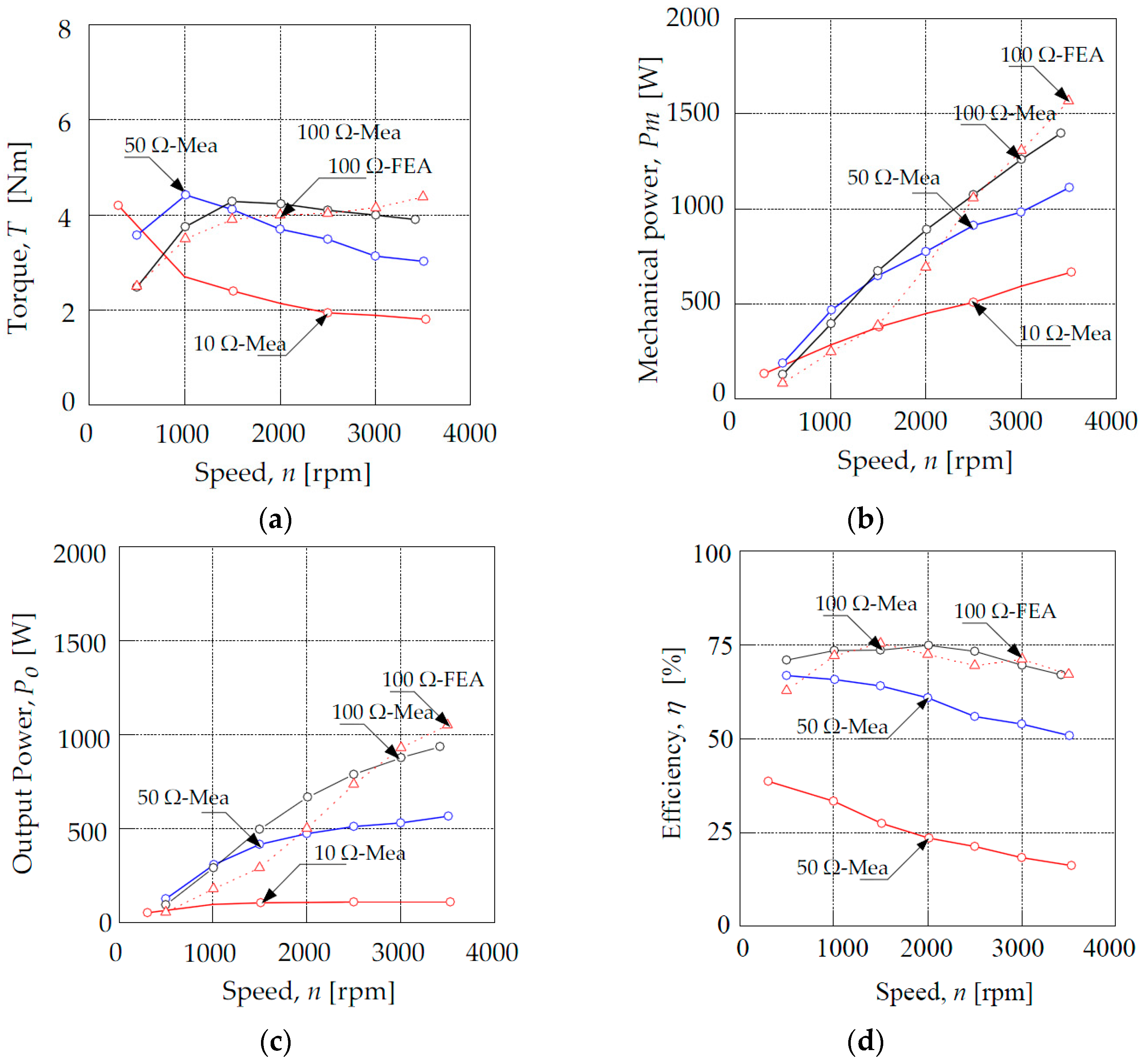
4. Results and Discussion

The analytical and the numerical result of flux linkages of DSSR-PMG is shown in Figure 12. Simulations are performed using Ansys Maxwell 16.0 and are calculated in 2-D magnetic analysis mode for faster with an accurate results. The value of flux linkages in DSSR-PMG is very important to the computations for the back EMF output. Figure 12a shows the sum of flux linkage in inner and outer stator with peak value reaching 0.16 Wb. The flux linkage generated through the simulations by the outer stator and inner stator alone is shown in Figure 12b. The result also compared with the analytical in order to verify the results. From the graph, the flux linkage produced by both inner and outer stator is 0.08 Wb. It shows that the outer and inner stator produce the same amount thus doubling the flux linkages. There is good agreement between numerical and analytical results of flux linkage, with the percentage error of 5%.
The cogging torque value against rotor position of DSSR-PMG is simulated in FEA at no-load condition as shown in Figure 13. The cogging torque produced by the interaction of poles and stator slot opening when the stator in open circuit at rated speed of 2000 rpm. The peak value of cogging torque is 0.3 mNm. The small value of cogging torque is due to the fractional numbers of slot per pole and the use of concentrated windings. In this DSSR-PMG, the self and mutual inductance against rotor position is shown in Figure 14. The self and mutual inductances are computed by FEA and it is observed that the maximum peak of self-inductance is 0.051 H, while, for mutual inductance, it is −0.0033 H. The consideration of inductance value is important because it gives significant impact to the performance of DSSR-PMG.
Figure 15 shows the analytical, simulation, and measurement results of no-load EMF of DSSR-PMG for operating speed of 2000 rpm. The analysis of back EMF begins with the inner stator as shown in Figure 15a. It shows that the peak value of EMF in simulation and measurement result in good agreement. Meanwhile, for analytical inner back EMF is slightly higher than measurement and simulation result, whereas the maximum peak value is 182 V. The outer stator back EMF is shown in Figure 15b. The peak value of generated back EMF for analytical, simulation, and measurement are 182 V, 178 V, and 162 V, respectively. The peak value in measurement is drop by 16 V compared with analytical or 9% percentage difference as expected. Since this DSSR-PMG is designed with the same air-gap flux density in the inner stator and the outer stator, both generate the same value of back EMF which is evident in Figure 15a,b.
With the inner and outer stator connected in series, the sum of back EMF is shown in Figure 15c. As can be seen from the graph, when the inner and outer stator coils are connected in series, the peak back EMF is nearly twice higher in comparison with that of a single stator connected. The back EMF increases by 46% when outer and inner stator coils are connected in series. The back EMF of both the inner air gap and outer air gap has same peak values, since the stator structures are identical. This increment is observed through the analytical, numerical and measurement results. The maximum peak of back EMF in this graph for analytical, numerical and measurement is 375 V, 341 V and 311 V, respectively. However, peak value of the back EMF in analytical is slightly higher than the simulation and measurement due to the limitations on the assumptions of linear conditions whereas the FEM simulation considered non-linear characterization of material properties. The increase in the back EMF increase the output voltage of DSSR-PMG due to the outer air gap and inner air gap produced the total same of flux density. The no-load EMF of analytical, simulation and measurement results are in good agreement. From Figure 15a–c, it is inferred that the back EMF is nearly in sinusoidal giving lower Total Harmonic Distortion (THD). THD of measured back EMF for inner stator and outer stator is 4.5%. THD is increased approximately 0.5% when inner stator and outer stator are connected in series. From Figure 15d, the average no-load EMF is proportional to the speed of DSSR-PMG. At the rated speed of 2000 rpm, the average EMF for analytical, simulation, and measurement are 182 V, 180 V, and 178 V, respectively. As seen, the average values of analytical and simulation of no-load back EMF are in good agreement, and are validated with that of the prototype measurement results. The error percentage of average back EMF between the analytical result compared with simulation and measured are 1.1% and 2.1%, respectively, which are still within the acceptable level. From the analysis above, it is concluded that the analytical result using permeance analysis method and simulations result made by the FEM are acceptable as compared to that of the measurement results.
Figure 16a–d shows the output performance analysis of the DSSR-PMG after rectified by rectifier bridge network. Figure 16a shows the torque of the generator for numerical, analytical and measurement. The torque decreases gradually at 10-Ω load, starting with the maximum torque of 4.2 Nm at the recorded speed of 303 rpm. The torque for both the load 50 Ω and 100 Ω increased from 500 rpm to 1500 rpm, before start decreasing as the speed increases. The torques needed for generator to operate at speed of 3000 rpm for the load of 10 Ω, 50 Ω and 100 Ω are 1.9 Nm, 3.1 Nm and 4.0 Nm respectively, while, for FEA-analytical, the torque at 100 Ω load is increased and reaches the maximum of 4.5 Nm at 3500 rpm speed. As seen from the graph, the torque of DSSR-PMG for 100 Ω load start to maintain at its maximum value although speed is increased. This is due to the maximum load current is reached and the generator is starts to saturate. Figure 16b shows the mechanical input power of DSSR-PMG. The graph shows the mechanical input power increased as the speed increases. The highest mechanical input power recorded for measurement with the resistive load of 10 Ω, 50 Ω and 100 Ω are 667 W, 1112 W and 1397 W respectively. While in FEA-analytical, the mechanical input power is increase proportionally to the speed with a significant difference approximately 8% compared with measurement at the speed of 1500 rpm.
Figure 16c shows the output power gradually increased as the speed increases for both measurement and FEA-analytical results. The measured output power of DSSR-PMG is calculated by multiplying the output voltage and current from the rectifier circuit. The measurement output power for 10 Ω increases between 300 rpm to 1500 rpm until it becomes saturated. At the speed mark of 3000 rpm, the output power for 10 Ω, 50 Ω and 100 Ω are 108 W, 530 W and 875 W, respectively, while, in FEA-analytical, the output power is approximately 650 W at rated speed at 2000 rpm. It is inferred from Figure 16c that the output power of FEA-analytical at the speed of 1000 rpm, 1500 rpm and 2000 rpm are not linear with the measurement result according to the mesh division layer setting in the FEM simulation. The values obtained from the magnetic flux are used to calculate the output power results for FEA-Analytical. However, the output power of measured and FEA result is still acceptable as the similarity of measurement and FEA result are achieved at the other DSSR-PMG speeds. The efficiency characteristic of DSSR-PMG is shown in Figure 16d. The measurement with 10 Ω load shows decreasing efficiency from maximum 38% at measured speed of 303 rpm and dropping to the minimum of 16% at speed of 3500 rpm. The efficiency for the 50 Ω also drops from the maximum 67% at the measured speed 500 rpm to 51% at speed of 3500 rpm. Moreover, the efficiency of the 100 Ω load increases gradually until maximum of 75% at the measured speed of 2000 rpm. For FEA-analytical, there is good agreement between measurement results, with the percent difference of only approximately 5%. The consistency of the efficiency curve in 100 Ω load gives advantages to the DSSR-PMG to operate at different operating ranges. It is observed that DSSR-PMG gives an optimization at the load of 100 Ω since the load current is smaller compared to others, thus has a high efficiency and better performance. The efficiency of DSSR-PMG can be increased and improved by considering several factors such as choice of core material, which can reduce the core losses that are dependent on the frequency and flux density of the machine.

5. Conclusions

In conclusion, the qualitative and quantitative analysis using FEM estimation and measurement of DSSR-PMG is investigated. The modeling of DSSR-PMG using Permeance Analysis Method (PAM) is introduced. Numerical design using Finite Element Analysis (FEA) is developed and a prototype of DSSR-PMG is fabricated. The Double Stator Permanent Magnet Generator with Slotted Rotor (DSSR-PMG) flux linkage and EMF are in good agreement with analytical, numerical and measurement results. From the analysis of the flux linkage, it is shown that the flux linkage is increased by 50% by implementing double stator compared to single stator topology with the same design structure. The back EMF of DSSR-PMG is increased by an average of 46% for measurement, analytical and simulation results. The DSSR-PMG is fabricated for performance analysis in term of output power and efficiency with several resistive loads. The DSSR-PMG topology shows consistent efficiency value, with the maximum power and efficiency 1000 W and 75% at 100 Ω resistive load, respectively. The implementation of the slotted rotor allows magnetic flux to be optimized and evenly distributed at the air gap of the inner and the outer stator.

Acknowledgments

The authors would like to thank Ministry of Higher Education Malaysia, Universiti Teknikal Malaysia Melaka (UTeM) and Universiti Putra Malaysia (UPM) for providing the research grant FRGS/1/2014/TK03/FKE/02/F00208, RACE/F3/TK14/FKE/F00250, PJP/2016/FKE(H15)/S01478 and FRGS/1/2015/TK04/FKE/02/F00260.

Author Contributions

Suhairi Rizuan Che Ahmad, Raja Nor Firdaus Kashfi Raja Othman, Siti Zulaika Mat Isa and Nor Aishah Md Zuki conceived and designed the simulations and experiments; Fairul Azhar Abdul Shukor, Zulkifilie Ibrahim, Md Nazri Othman and Chockalingam Aravind Vaithilingam contributed in analysis; and Suhairi Rizuan Che Ahmad and Raja Nor Firdaus Kashfi Raja Othman wrote the paper.

Conflicts of Interest

The authors declare no conflict of interest.

Abbreviations

The following abbreviations are used in this manuscript:
DSSR-PMGDouble Stator Slotted Rotor Permanent Magnet Generator
PAMPermeance Analysis Method
NdFeBNeodymium Boron Iron
rpmRotation per Minute
EMFElectromotive Force
FEAFinite Element Analysis
PMGPermanent Magnet Generator
ABSAcrylonitrile Butadiene Styrene
PMPermanent Magnet
PmMechanical input power
PoOutput power
RLResistive load
RcCoil resistance

References

  1. Grauers, A. Efficiency of three wind energy generator systems. IEEE Trans. Energy Convers. 1996, 11, 650–657. [Google Scholar] [CrossRef]
  2. Chan, T.F.; Lay, L.L. Permanent magnet machines for distributedpower generation: A review. In Proceedings of the IEEE Power Energy Society General Meeting, Tampa, FL, USA, 24–28 June 2007; pp. 1–6.
  3. Fan, Y.; Chau, K.T.; Cheng, M. A new three-phase doubly salient permanent magnet machine for wind power generation. IEEE Trans. Ind. Appl. 2006, 42, 53–60. [Google Scholar]
  4. Chen, Y.; Pillay, P.; Khan, A. PM wind generator topologies. IEEE Trans. Ind. Appl. 2005, 41, 1619–1626. [Google Scholar] [CrossRef] [Green Version]
  5. Feng, C.; Cui, S.; Kang, C. Performance Analysis of Double-stator Starter Generator for the Hybrid Electric Vehicle. In Proceedings of the 12th Symposium on Electromagnetic Launch Technology, Snowbird, UT, USA, 25–28 May 2004; pp. 499–502.
  6. Chai, F.; Cui, S.; Cheng, S. Performance analysis of double-stator starter generator for the hybrid electric vehicle. IEEE Trans. Magn. 2005, 41, 484–487. [Google Scholar] [CrossRef]
  7. Vaithilingam, C.A.; Misron, N.; Zare, M.R.; Aris, I.; Marhaban, M.H. Computation of Electromagnetic Torque in a Double Rotor Switched Reluctance Motor Using Flux Tube Methods. Energies 2012, 5, 4008–4026. [Google Scholar] [CrossRef]
  8. Aravind, C.V.; Grace, I.; Rozita, T.; Rajparthiban, R.; Rajprasad, R.; Wong, Y.V. Universal computer aided design for electrical machines. In Proceedings of the 2012 IEEE 8th International Colloquium on Signal Processing and its Applications (CSPA), Melaka, Malaysia, 23–25 March 2012; pp. 99–104.
  9. Liu, C.; Chau, K.T.; Jiang, J.Z.; Jian, L. Design and Analysis of a Stator-Doubly-Fed-Doubly-Salient Permanent-Magnet Machine for Automotive Engines. IEEE Trans. Magn. 2006, 42, 1494–1497. [Google Scholar]
  10. Misron, N.; Suhairi, R.; Firdaus, R.N.; Vaithilingam, C.A.; Wakiwaka, H.; Nirei, M. Comparative Evaluation on Power-Speed Density of Portable Permanent Magnet Generator For Agriculture Applications. Prog. Electromagn. Res. 2012, 129, 345–363. [Google Scholar]
  11. Liu, C.; Chau, K.T.; Jiang, J.Z.; Jian, L. Design a new outer-rotor permanent magnet hybrid machine for wind power generation. IEEE Trans. Magn. 2008, 44, 3470–3472. [Google Scholar]
  12. Niu, S.; Chau, K.T.; Jiang, J.Z.; Liu, C. Design and Control of a New Double-Stator Cup-Rotor Permanent-Magnet Machine for Wind Power Generation. IEEE Trans. Magn. 2007, 43, 2501–2503. [Google Scholar] [CrossRef] [Green Version]
  13. Firdaus, R.N.; Misron, N.; Vaithilingam, C.A.; Nirei, M.; Hiroyuki, W. Improvement of Energy Density in Single Stator Interior Permanent Magnet Using Double Stator Topology. Math. Probl. Eng. 2014, 2014, 787382. [Google Scholar] [CrossRef]
  14. Delforge, C.; Lemaire-Semail, B. Induction machine modelling using finite element and permeance network methods. IEEE Trans. Magn. 1992, 42, 2092–2095. [Google Scholar]
  15. Touati, S.; Ibtiouen, R.; Touhami, O.; Djerdir, A. Experimental investigation and optimization of permanent magnet motor based on coupling boundary element method with permeances network. Prog. Electromagn. Res. 2011, 111, 71–90. [Google Scholar] [CrossRef]
  16. Cros, J.; Viarouge, P. Synthesis of high performance PM motors with concentrated windings. IEEE Trans. Energy Convers. 2002, 17, 248–253. [Google Scholar] [CrossRef]
  17. Magnussen, F.; Sadarangani, C. Winding factors and Joule losses of permanent magnet machines with concentrated windings. In Proceedings of the IEEE International Electric Machines and Drives Conference (IEMDC’03), Madison, WI, USA, 1–4 June 2003; Volume 1, pp. 333–339.
  18. Chung, S.; Kim, J.; Koo, D.; Woo, B.; Hong, D.; and Lee, J. Fractional slot concentrated winding permanent magnet synchronous machine with consequent pole rotor for low speed direct drive. IEEE Trans. Magn. 2012, 48, 2965–2968. [Google Scholar] [CrossRef]
  19. Paulsamy, S. Reduction of Cogging Torque in Dual Rotor Permanent Magnet Generator for Direct Coupled Wind Energy Systems. Sci. World J. 2014, 2014, 987062. [Google Scholar] [CrossRef] [PubMed]
Figure 1. Basic structure of three-phase DSSR-PMG.
Energies 10 00411 g001
Figure 2. Flowchart of DSSR-PMG for FEA modeling and PAM modeling.
Energies 10 00411 g002
Figure 3. Coil vectors and winding arrangement of DSSR-PMG, (a) Coil vectors; (b) Winding arrangement.
Energies 10 00411 g003
Figure 4. Flux distribution of DSSR-PMG.
Energies 10 00411 g004
Figure 5. General electrical equivalent circuit.
Energies 10 00411 g005
Figure 6. Flux flow of three phase DSSR-PMG.
Energies 10 00411 g006
Figure 7. Equivalent and simplified magnetic circuit of DSSR-PMG, (a) Equivalent magnetic circuit; (b) Simplified magnetic equivalent circuit.
Energies 10 00411 g007
Figure 8. B-H curve and operating point of permanent magnet.
Energies 10 00411 g008
Figure 9. Flowchart of experimental process.
Energies 10 00411 g009
Figure 10. Prototype of DSSR-PMG, (a) Cross-sectional view; (b) Assembled DSSR-PMG.
Energies 10 00411 g010aEnergies 10 00411 g010b
Figure 11. Block diagram and experimental setup of DSSR-PMG, (a) Block diagram for experimental setup; (b) Experimental setup for measurement.
Energies 10 00411 g011
Figure 12. Flux linkage of DSSR-PMG, (a) FEA simulation; (b) FEA simulation and analytical.
Energies 10 00411 g012
Figure 13. Cogging torque.
Energies 10 00411 g013
Figure 14. Winding inductances.
Energies 10 00411 g014
Figure 15. Back EMF of DSSR-PMG, (a) Inner back EMF; (b) Outer back EMF; (c) Inner + outer back EMF; (d) Back EMF at different operating speed.
Energies 10 00411 g015
Figure 16. Performance characteristic of DSSR-PMG prototype with various loads, (a) Torque; (b) Mechanical input power; (c) Output power; (d) Efficiency.
Energies 10 00411 g016
Table 1. DSSR-PMG parameters.
ParametersDSSR-PMG
Outer stator diameter (mm)156
Inner stator diameter (mm)86
PM volume (m3)6.3 × 10⁻⁷
PM height, hm (mm)6
PM width, wm (mm)2
Coil size (mm)0.7 (0.1 mm insulation)
Stack length (mm)52.5
Outer air gap, go (mm)0.5
Inner air gap, gi (mm)0.5
No. of turns of inner coil, Ni55
No. of turns of outer coil, No55
Stator tooth face angle (°)15
Outer stator yoke height, hco (mm)12
Inner stator yoke height, hci (mm)15
Table 2. DSSR-PMG coil arrangements.
PhasePolarity
PositiveNegative
AS1, S3, S10, S12S2′, S11
BS7, S9, S16, S18S8′, S17
CS4, S6, S13, S15S5′, S14

