
Coordinated Control and Fault Protection Investigation of a Renewable Energy Integration Facility with Solar PVs and a Micro-Turbine


Department of Electrical Engineering, The Hong Kong Polytechnic University, Hong Kong, China
Energies 2017, 10(4), 423; https://doi.org/10.3390/en10040423
Submission received: 16 February 2017
/
Revised: 21 March 2017
/
Accepted: 22 March 2017
/
Published: 23 March 2017
Abstract
:In this paper, a renewable energy integration facility (REIF) with photovoltaic (PV) distributed generation resources for micro-grid applications is studied. In grid-tied operation, the PV system together with the grid supply the power to the local loads while the surplus energy is fed back to the grid. In stand-alone mode, a gas micro-turbine is operated as a master to establish the common AC bus voltage to which the PV inverters can synchronize The experimental results demonstrate the stable operation of the REIF under various generation and load conditions. The power quality can meet the IEEE Standard 1547. Furthermore, the responses of the REIF under different fault conditions are investigated. Relevant protection mechanisms are then developed, providing insights into the fault protection for the future grid.
1. Introduction
The rapid depletion of fossil fuels, rising demand for electricity and tightening government policies on the reduction of greenhouse gas emissions are driving major changes in electricity generation and consumption patterns all around the world. In the last few decades, serious concerns were raised about distributed generation units (DGs), especially the renewable energy resources, such as wind and solar photovoltaic (PV) systems [1,2]. More recently, micro-grids have attracted much attention as the local low voltage power systems integrating DGs into the network. These small micro-grids will then be integrated into the intelligent power system with the physical highway and digital highway, namely the smart grid [3,4,5,6].
Considering that most power outages and disturbances occur in the distribution network, it is widely recognized worldwide that the first step towards the smart grid should start at the bottom of the chain, in the distribution systems. As a systematic integration of DGs system, a micro-grid can offer many technical advantages in terms of power quality and energy management [7,8]. The basic requirements of micro-grids are the high quality point of common coupling (PCC) voltage in both grid-tied and stand-alone operations in terms of stable voltage amplitude and frequency. In addition, the load changes should be picked up by the DGs. However, due to the intermittent nature of the renewable sources and fluctuated load profile, it is difficult to operate a micro-grid installed with only renewable generation units. The power quality will be deteriorated if neither ancillary devices nor additional control approaches were introduced.
So far, many control strategies have been proposed to allow inverters to operate in parallel. In particular, droop control is widely used, where the output voltage of the DGs can be adjusted; hence, the active and reactive power can be regulated [9,10]. Recently, various improvements have been proposed to obtain better transient performance and more accurate power sharing. For example, better transient response was obtained by introducing derivative-integral terms [11,12,13,14]. The power sharing accuracy was enhanced by employing a virtual power frame transformation or a virtual flux [15,16,17]. In [18], an angle controller was proposed to minimize frequency variation by drooping the inverter output voltage phase angle instead of the frequency. However, it is difficult to know the initial angle of the other inverters without the help of GPS.
For the techniques mentioned above, however, there is a major limitation, as most of those works have only studied a simplified configuration with only two DGs connected in parallel. Besides, the inputs of these DGs are usually assumed as constant DC sources, whereas the practical power generation behaviors of DGs, such as solar PVs, are not considered. Since the micro-grid laboratory system not only can serve as a test bed, but also provide a verification platform, the development of a laboratory-scale micro-grid system with actual DGs and local loads becomes very practical and useful. Several micro-grid technologies in energy management, control strategies, power quality, laboratory systems and field tests have since been studied [19,20,21,22,23].
The power management strategies for micro-grids with multiple DGs were studied in [19], but only simulation results were presented. The work in [21] developed a supervisor control to satisfy the load power demand and to maintain the state of charge of the battery bank; but, it only focused on the stand-alone mode, and the micro-grid response under grid connection was not investigated. The work in [22] proposed a central energy management and local power management at the customer side for micro-grid applications. In [23], a Consortium for Electric Reliability Technology Solutions (CERTS) micro-grid test bed was tested, but fault protection issues were not considered. A hybrid microgrid comprised of PV, wind and hydro energy resources was presented in [24]. The blueprint to construct a mini grid for high altitude regions considering available resources and local load profile was introduced in [25]. As the grid incorporates smart metering and information technology, the network security of future smart microgrids was discussed in [26].
Another important issue about the micro-grid is the fault protection. So far, many efforts have been made for the power flow of micro-grids. However, the fault protection at the distribution level for a micro-grid system is seldom reported. Besides, the literature related to faults on micro-grids is almost exclusively devoted to the detection of islanded conditions [27,28]. Predictive diagnosis of a high-power transformer for uninterruptible power supplies is developed in [29,30], which shows possible applications in high-power microgrids. In [31], an intelligent power switching for harsh automotive applications is proposed at the circuital component level against high voltage, parasitics effects and over-current. To the authors’ best knowledge, however, there is little work reported to address the faults occurring within the micro-grid itself. As the DGs penetration is likely to increase rapidly in the future grid, the faulty protection environment becomes more complex. Consequently, a deeper understanding of the micro-grid behavior under fault conditions is required.
This paper focuses on a laboratory renewable energy integration facility (REIF) incorporated with solar PVs, a gas micro-turbine and a programmable load. The first objective is to study the behaviors of PVs and the gas micro-turbine. After that, the coordinated operation of the REIF for reliable power delivery and high power quality will be presented. The second objective of this paper is to investigate the response of the REIF with a large amount of renewable sources and other distributed generation systems during faults and to consequently propose suitable protection mechanisms. The experiments described in this work make strides towards identifying, quantifying and understanding the challenges of micro-grid design and operation, in the hope that such knowledge will inform and focus future micro-grid research.
2. The Renewable Energy Integration Facility Configuration
Figure 1 shows the laboratory REIF structure under study. It is comprised of solar PV panels, a gas micro-turbine, a programmable load bank and a motor as the load. All of these distributed units are connected to a common AC bus in parallel with a nominal line-to-line voltage of 415 V and a nominal frequency of 50 Hz. The REIF can operate both connected to the utility grid through the static transfer switch (STS) or autonomously in stand-alone mode. The delivery of control commands and the measurement of the system variables are achieved by using a supervisory control and data acquisition (SCADA) system. The system information, such as PV inverter outputs and AC bus voltage, are collected from the sensors and sent to the central computer every 1 ms. In the other direction, the central computer delivers control commands to the programmable logic controllers (PLCs) to control the load bank, gas micro-turbine, STS, etc. A control panel is built using LabVIEW in the central computer as the human machine interface (HMI).
2.1. Solar Photovoltaics
Solar energy is a renewable source being widely exploited all around the world. Photovoltaic (PV) technology involves converting solar energy directly into electrical energy by means of solar cells. Each series of PV panels in the array is connected in the form of a single string, with each string connected to a single phase inverter. There are in total 15 inverters installed in front of the control room. These inverters are then distributed evenly across the three phase common AC bus with a total rated output power of about 20 kW. The PV array is installed on the roof of the laboratory. They are controlled to operate at the maximum power point tracking (MPPT) with unit power factor. The performance of a PV array can be affected by many factors, such as temperature, solar irradiance, shading, etc.
2.2. Micro-Turbine
Another type of DG unit available in the laboratory is a 30 kW three-phase gas micro-turbine system. It is a synchronous generator driven by a micro-turbine via a gearbox ranging from 50,000 to 12,000 rpm. The generator supplies electric power to the common AC bus through a back-to-back converter. The high frequency AC power generated by the synchronous generator is first rectified to DC and then converted to AC. Both the amplitude and the frequency of the micro-turbine system output voltage are controllable, and this can supply a customer’s base load or can be used for standby, peak shaving and cogeneration applications. In this work, when the REIF is operated in stand-alone mode, the micro-turbine system is used to establish a stable common AC bus voltage and provided a voltage signal to which the PV inverters can synchronize.
2.3. Programmable Load Bank and Induction Motor
The load bank consists of a 63 kW resistive load, a 63-kVAR inductive load and a 63 kVAR capacitive load. These are arranged in a binary fashion. For instance, the resistors can be arranged to consume 1 kW, 2 kW, 4 kW, 8 kW, 16 kW and 32 kW of active power, such that any amount of power consumption can be achieved by a combination of these six resistors, following the standard binary code. In addition, an induction motor was also used in this study with the purpose of introducing an apparent fault, which will be discussed further in Section 5.
3. Demonstration of the Behavior of Renewable Energy Resources
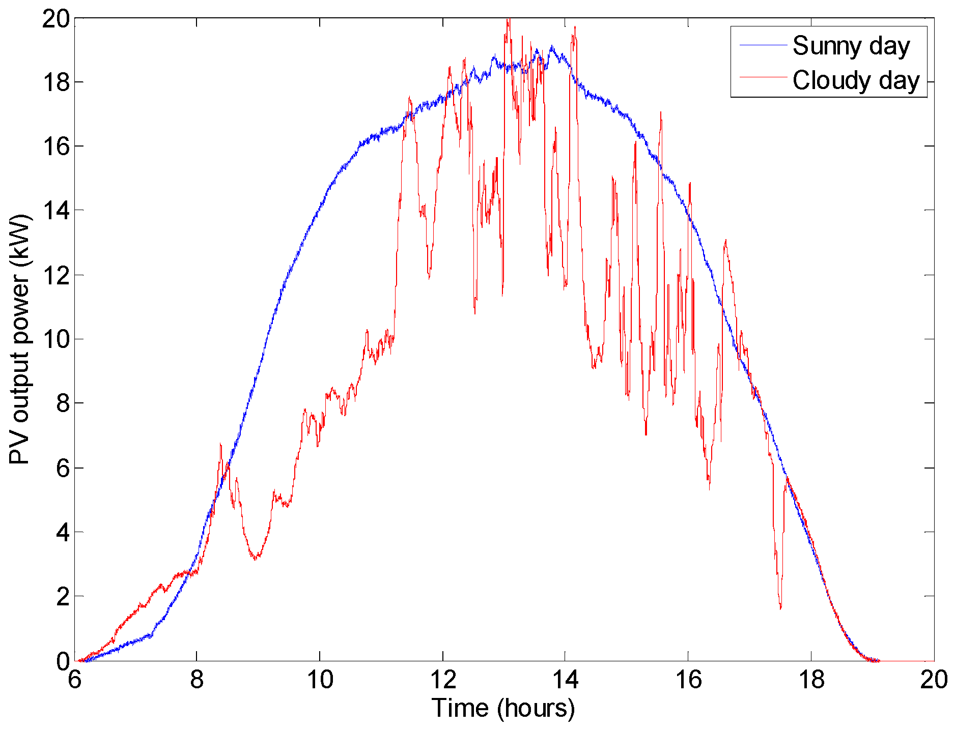
In the REIF, the renewable energy resources are the solar PVs. They are connected to the common AC bus through inverters with the MPPT operation. The power output of the PV system can be affected by many factors, such as temperature, sun light strength, shading, etc. Figure 2 shows the total output power of the PV array from 6:00 a.m. to 8:00 p.m. on a sunny day and a cloudy day, respectively. It can be seen that the PV output power of a sunny day increased smoothly in the morning until it reached the peak value of about 19 kW at around 2 p.m., then decreased gradually in the afternoon and hit the bottom of 0 kW at around 7 p.m. However, the output power of the PV system features an obvious fluctuating characteristic on a cloudy day due to the fluctuating irradiation.
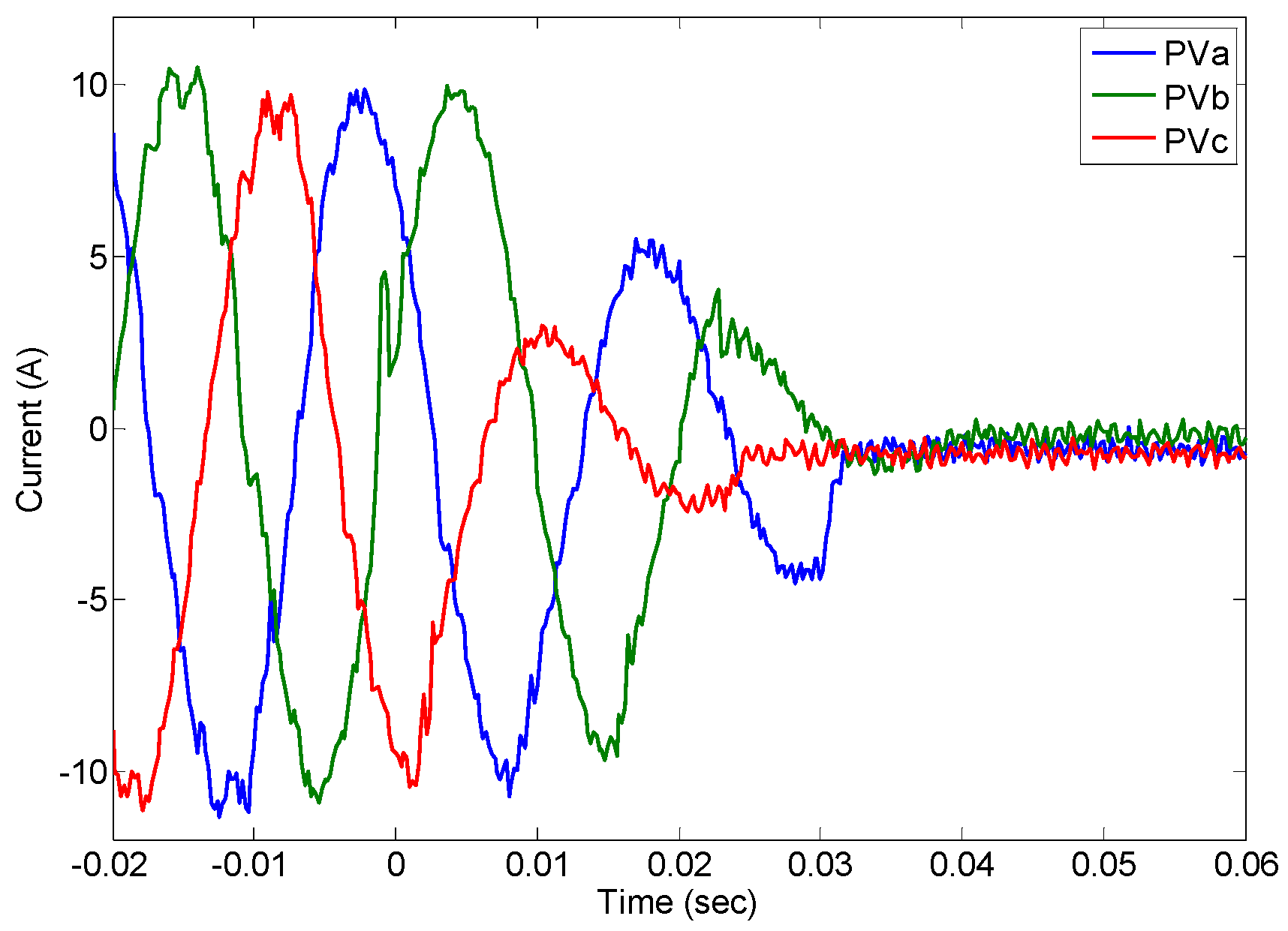
Figure 3 shows the response of a PV inverter to the loss of the external grid at zero seconds on the horizontal axis; this is the current supplied to the grid from one of the inverters. It can be seen that the inverter stopped supplying current completely in about 30 ms after grid disconnection, and the other inverters behaved in a similar manner. Figure 4 shows the response of the total three-phase output currents of the PV system to the loss of the external grid. It can be found that this type of inverter loses the ability to supply power if there is no external voltage source to which the inverters can synchronize.
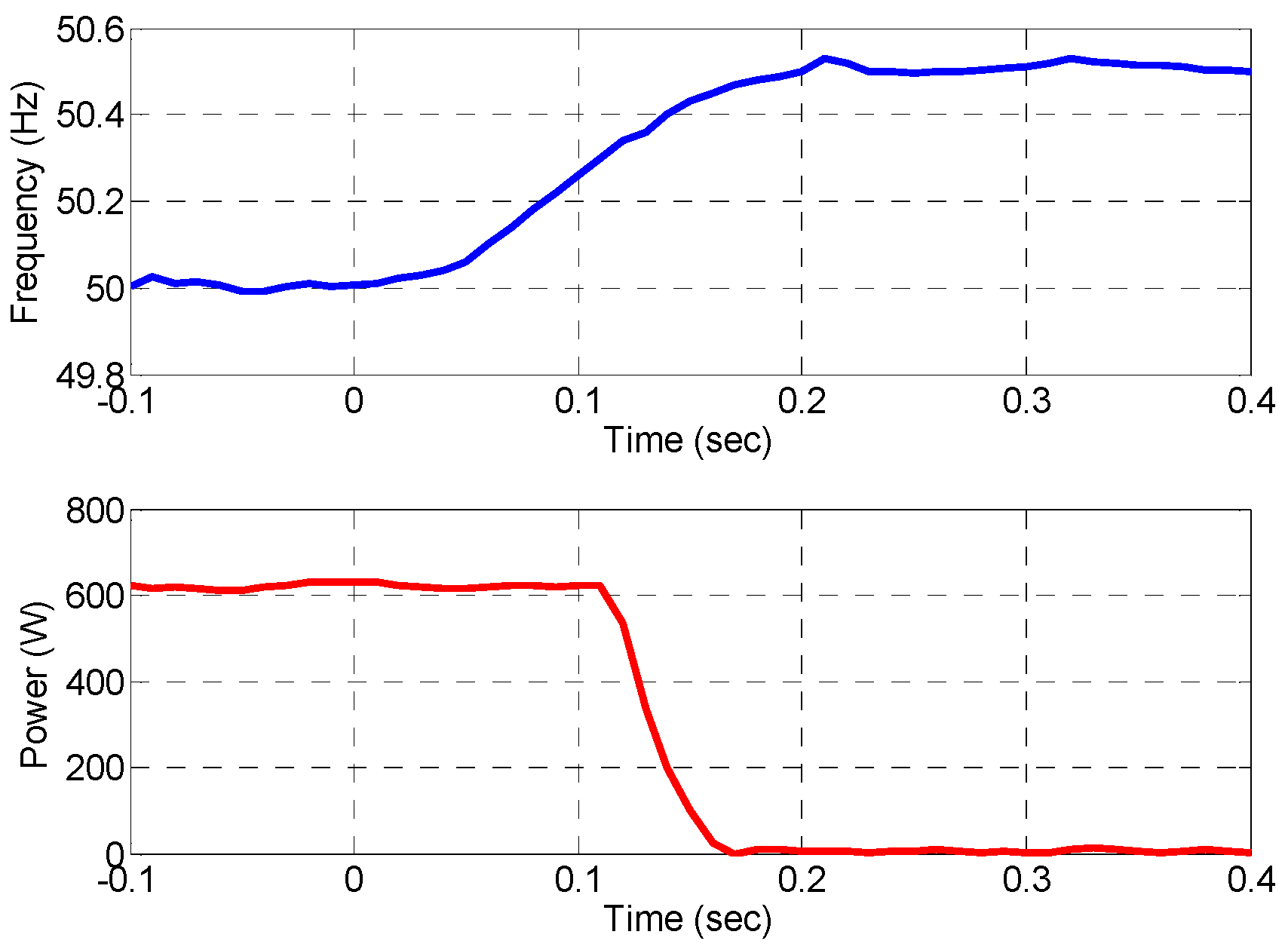
Figure 5 shows the response of a PV inverter to the frequency variation on a distribution network. Here, the frequency, represented by the blue line, varies from 50 Hz to 50.5 Hz. It can be observed that the power output from the PV inverter drops abruptly from 600 W to zero after 50 ms. The inverter response to the frequency decreasing was also investigated; it stopped supplying power when the frequency dropped down to around 49.8 Hz, which is not shown here. This shows that the inverters are very sensitive to the frequency disturbance.
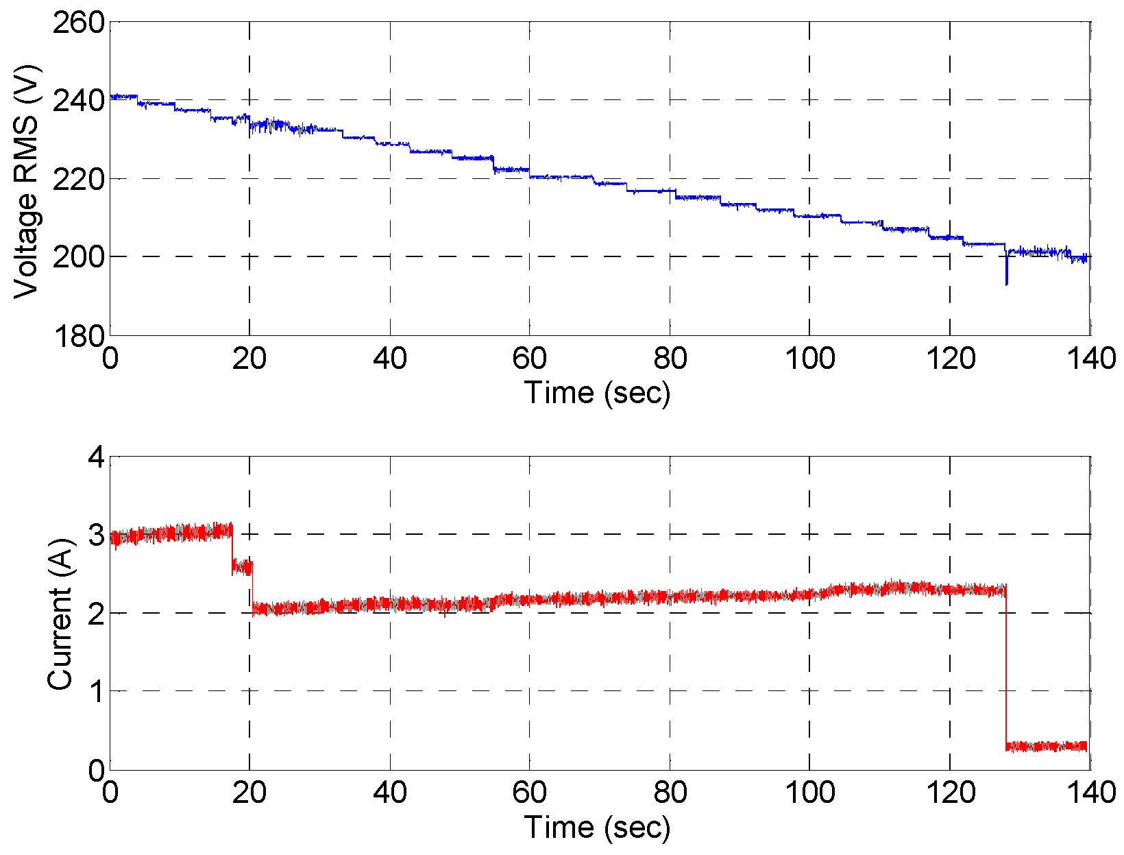
Figure 6 presents the response of the PV inverter to the voltage variation. Here, the phase-neutral voltage rms value, represented by the blue curve, is decreased gradually 3 V at each step. It can be found that the PV output current dropped rapidly to 2 A when the voltage decreased to 225 V, and the PV inverter shut down completely if the voltage dropped below 202 V. A similar feature can be observed that PVs shut down completely when the voltage rises up to 251 V, which is not shown here either.
Based on the above observation, the following characteristics of this PV system can be obtained:
- These inverters are not suitable for use in an islanded micro-grid, unless a reliable generation source is available as a master to provide a synchronization voltage.
- The inverters respond very rapidly to the voltage disturbance in both frequency and amplitude. Consequently, high-quality voltage must be supplied to maintain the normal operation of the PV system.
4. Energy Management Strategy
The laboratory REIF is depicted in Figure 1. This facility incorporates a 20 kW solar PV array (on the roof), a 30 kW gas micro-turbine, a programmable load bank, an induction motor and a high speed SCADA system, as described previously. In order to exploit the solar energy effectively and supply reliable and high quality power to the local loads, proper operation approaches are required.
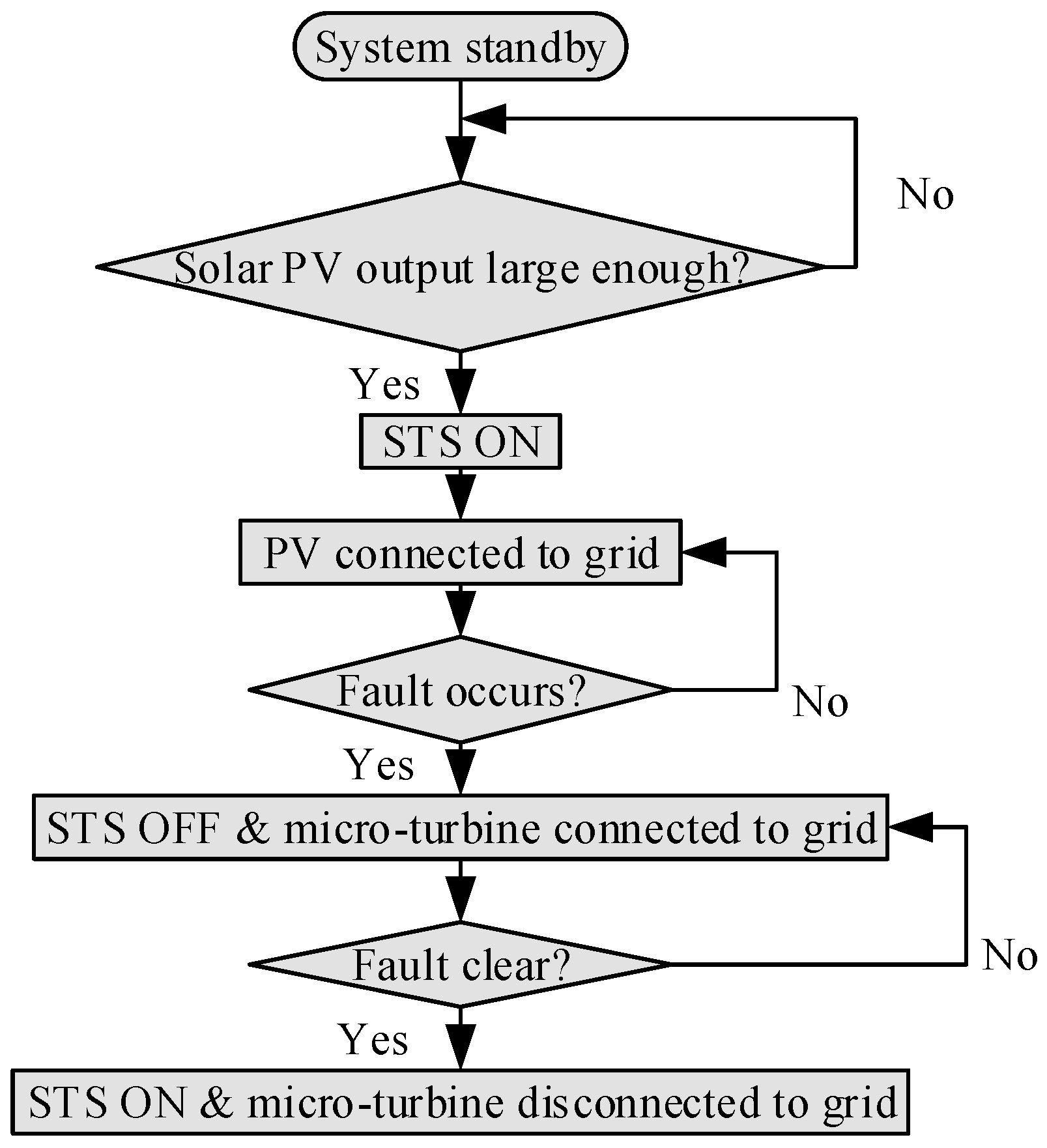
Figure 7 illustrates the coordinated operations of multiple renewable/conventional generators under different modes. Initially, the total output from the PVs is detected. The PV inverters will be connected to the grid once the PV output reaches a pre-defined value. In grid-tied mode, the PVs and the utility grid supply the electric power to the loads. If the power generated by the DGs is greater than the load demand, the excess will be fed back to the grid. On the contrary, if the amount of power generated is lower than the demand, additional power will be imported from the grid.
When faults occur in the grid, the STS is switched off, and the REIF is isolated from the utility grid. In stand-alone operation, as the utility grid voltage is not available, there are two important issues that need to be addressed. First, a high-quality voltage is required at the common AC bus to maintain the normal operation of the PV system. Second, the PV system is operated at MPPT with unit power factor, i.e., it only generates active power, which cannot meet the requirement of reactive power consumption of the loads. In this case, a micro-turbine system is employed not only to provide the voltage source that the PV inverters can synchronize to, but also to balance the active and reactive load demands.
4.1. Case Study 1: Grid-Tied Mode
In this test, the PV system and the programmable load bank are connected to the common AC, bus and the system is then further connected to the utility grid via the STS. The PVs simply attempt to push as much power as possible onto the common AC bus. If the power generation is greater than the load demand, the excessive power will be injected into the grid; if the power generation is smaller than the load demand, more power will be imported from the grid. The power flow within the microgrid can be expressed as:
where PL, PPV and PG are the active powers consumed by the local load, generated by the PV system and supplied by the utility grid, respectively. QL and QG are the reactive power consumed by the local load and provided from the utility grid, respectively.
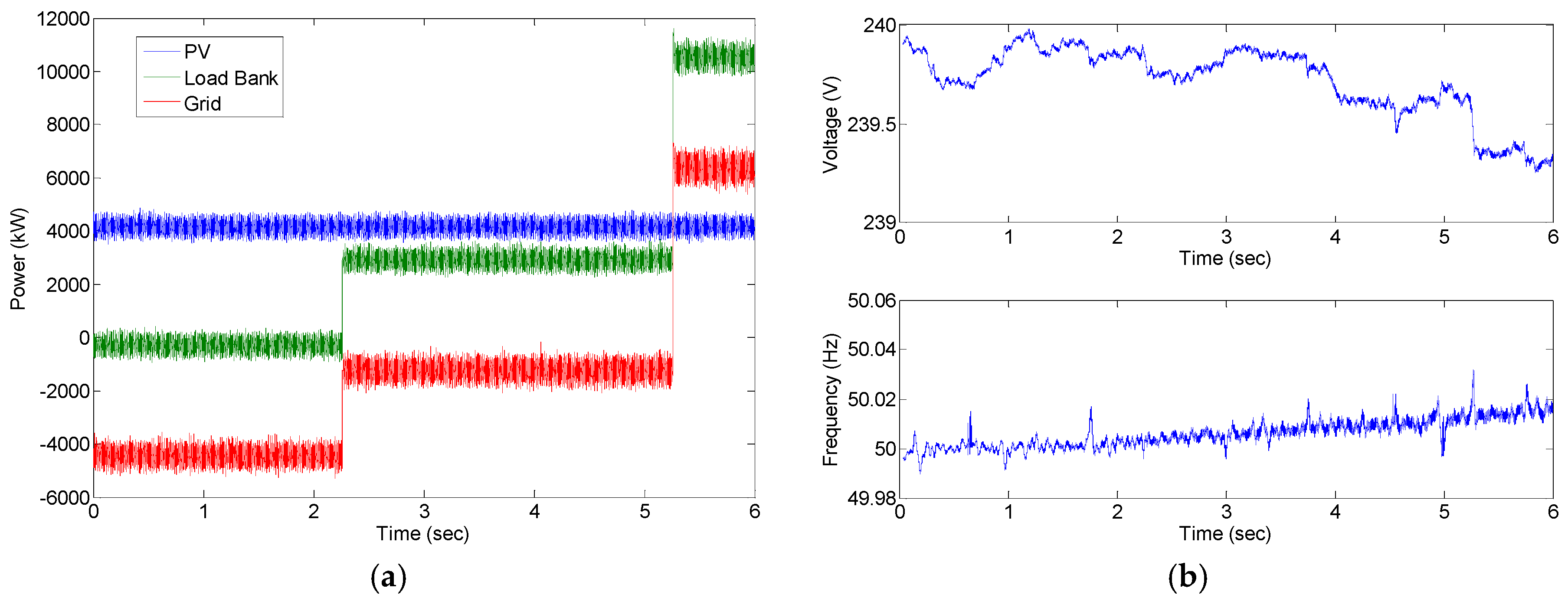
In this experiment, the total power generated by the PV panels at the time of the test was about 4.5 kW. Initially, the load bank was set to zero, then increased to 3 kW (less than the PV output power) and 10 kW (greater than the PV output power) at 2.2 s and 5.3 s, respectively. Under such operation, the power flow and the power balance within the system are of interest. The voltage response at the common AC bus in terms of amplitude and frequency will also be investigated.
Figure 8a presents the active power sharing between the PVs and the utility grid. It can be found that the PVs provided around 4.5 kW active power throughout this test. At no-load condition at the beginning, the power flow from the utility is −4.5 kW, which means that the power generated by the PVs was totally fed back to the utility grid. When the load was added to 3 kW at 2.2 s, the power provided by the utility becomes −1.5 kW. This is expected, as the PVs are able to cover all of the load demand, leading to only 1.5 kW (4.5 kW − 3 kW = 1.5 kW) surplus exported to the utility. When the load was increased to 10 kW at 5.3 s, it can be seen that additional 5.5 kW (10 kW − 4.5 kW = 5.5 kW) power was required from the utility because the load demand was greater than the power generation from the PV system.
Figure 8b presents the voltage transient at the PCC (i.e., the voltage of common AC bus). The voltage quality under the load variation condition is the main concern. Thanks to the connection of the utility grid, the microgrid voltage is stable during transients with only a 0.6 V variation in magnitude and a 0.02 Hz deviation in frequency.
When faults occur in the grid, the STS is switched off, and the REIF is isolated from the utility grid. In stand-alone operation, as the utility grid voltage is not available, there are two important issues that need to be addressed. First, a high-quality voltage is required at the common AC bus to maintain the normal operation of the PV system. Second, the PV system is operated at MPPT with unit power factor, i.e., it only generates active power, which cannot meet the requirement of the reactive power consumption of the loads. In this case, a micro-turbine system is employed not only to provide the voltage source that the PV inverters can synchronize to, but also to balance the active and reactive load demands.
4.2. Case Study 2: Stand-Alone Mode
As demonstrated in Section 3, there are three important issues that need to be addressed. First, the inverters of the solar PV system require an external AC voltage source for normal operation. Second, a high-quality common AC bus voltage is required to maintain the normal operation of the PV system. Third, the PV system is operated at MPPT with unit power factor, i.e., it only generates active power, which cannot meet the requirement of the reactive power consumption of the loads. Since the utility grid is unavailable in islanded operation, a micro-turbine system is utilized here. The micro-turbine system plays an important role of providing not only the voltage source that the PV inverters can synchronize to, but also powers to the local loads. As a result, the PV together with the micro-turbine system supplied power to the load bank. In fact, the micro-turbine system reacts to smooth the gap in active power between the consumption by the load and generation by the PV system and then provide all of the reactive power required from the load. Consequently, the power flow within the REIF can be described as:
where PMT and QMT are the active power and reactive power generated by the micro-turbine system, respectively. When the REIF is disconnected from the utility grid, the micro-turbine starts to work as a master in islanded operation, which features the following functions:
- (1)
- Establish a common AC bus voltage for the REIF;
- (2)
- Provide an external AC voltage source for the PV inverters to synchronize to;
- (3)
- Pick up any load change together with the PV system.
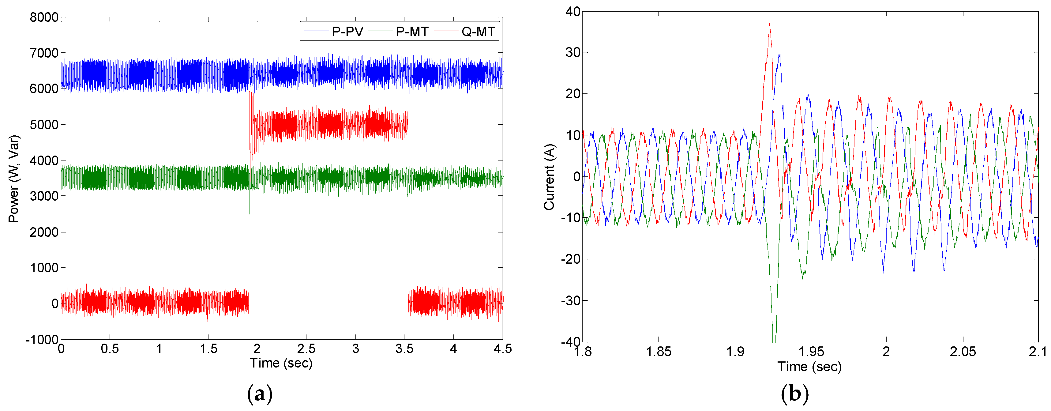
At the time of this experiment, the PV system produced about 6.5 kW of active power. The load profile was set in such a pattern that resistive load was kept constant at 10 kW, while a 5 kVAR inductive load was added and removed at 1.9 s and 3.5 s, respectively. The objective of this test is to verify the stability and feasibility of the REIF in stand-alone mode under various load profiles.
Figure 9 shows the power sharing between the distributed generations in stand-alone mode. It can be observed that the micro-turbine supplied active power to the load bank together with PVs during the entire test. At t = 1.9 s, the micro-turbine system automatically increased its reactive power from 0 to 5 kVAR to meet the new load demand, while the PVs continued to supply around 6.5 kW of active power. At t = 3.5 s, the inductive load was removed; the micro-turbine system continued to provide 3.5 kW of active power, while the reactive power dropped back to 0 kVAR. The output currents of the micro-turbine system during the load change are shown in Figure 9b. In the stand-alone mode, the stability of the common AC bus voltage is the main concern, and it is measured during the variation of load change, as depicted in Figure 9c. Due to the excellent control capability of the micro-turbine system, the REIF voltage is stable during the entire islanded operation.
4.3. Power Quality
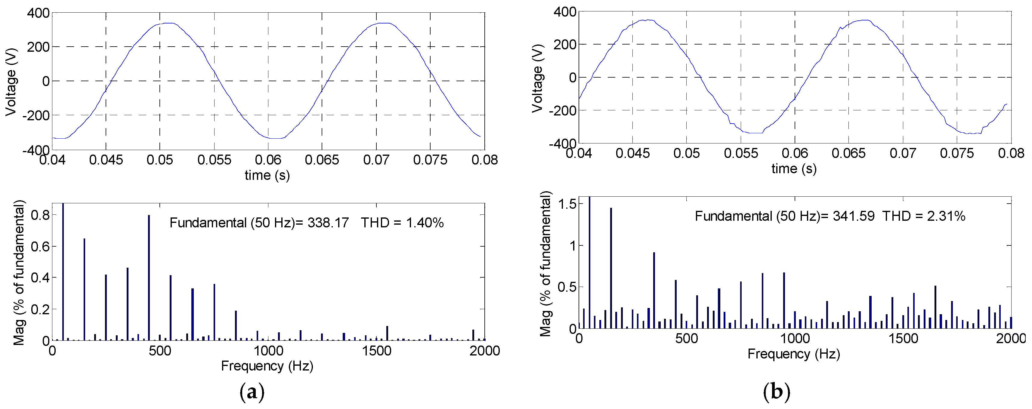
Figure 10 compares the harmonic spectrum of the common AC bus voltage for grid-connected and islanded operations. It can be seen that both grid-connected and islanded operation can provide high-quality power, with only 1.40% voltage total harmonic distortion (THD) and 2.31% voltage THD, respectively.
In order to better validate the feasibility of the proposed REIF operation, the power quality results are summarized in Table 1, where the performance of the common AC bus voltage is compared with the IEEE Standard 1547 [32]. The results show that the REIF at grid-connected mode supplies better quality power compared with islanded mode. Most importantly, the power quality of both grid-connected and islanded operation can meet the standard requirement.
5. Faulty Protection Investigation
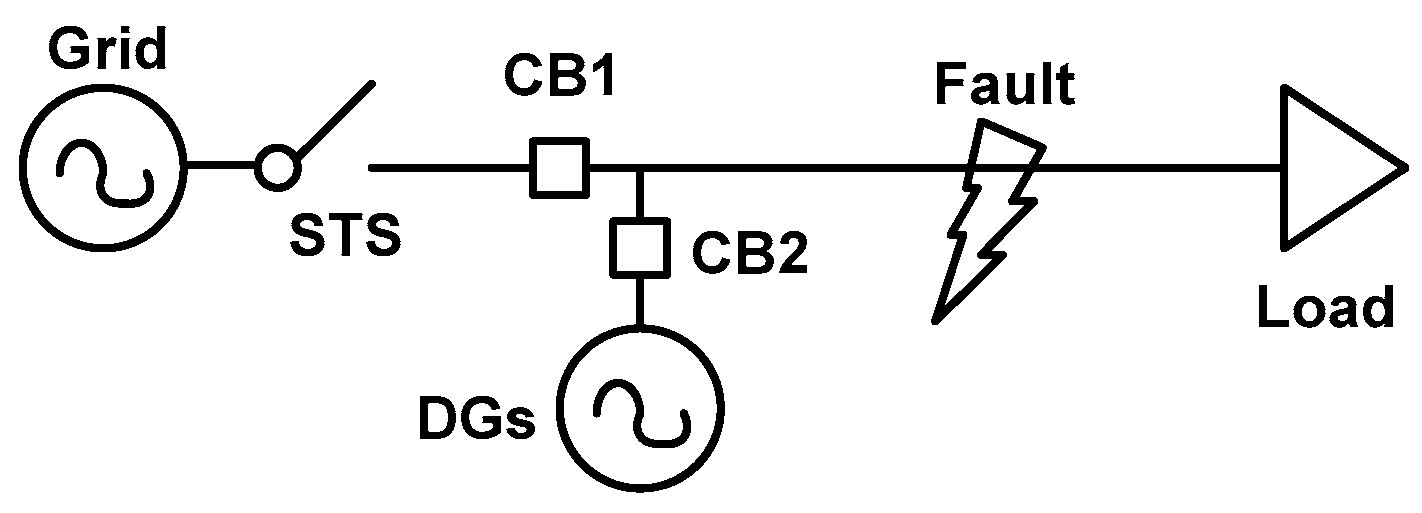
The future grid is likely to integrate a significant amount of renewable energy sources and other distributed generations. It is necessary to investigate the response of the REIF under grid faults and develop proper protection mechanisms. It is worth mentioning that existing fault detection systems rely mainly on the assumption that a short-circuit type fault will result in overshoot current that is much greater than the normal level. Thus, anomaly detection is usually accomplished by a fixed threshold. In this test, our objective is to identify whether the increasing penetration of DGs will lead to an increased fault current and whether the existing protection mechanism is adequate to deal with this new situation. Figure 11 illustrates a simplified diagram for the fault test, where CB1 and CB2 are the circuit breakers.
It is noted that there are various types of grid faults out there. Due to the page limitation, here, we will take the most common type of faults in the industry for example: short circuit faults. In order to investigate this type of fault, an apparent fault is introduced by starting an induction motor directly without any starting aid.
5.1. Case 1: Faults in Grid-Tied Mode
In this scenario, the PVs and the load bank are connected to the AC common bus, and the STS is switched on. The micro-turbine system is also included in this test as another type of DG. The PVs and the micro-turbine system generated 6 kW and 30 kW at the time of this test, respectively, with 20 kW of resistive load bank.
The response of the REIF to the short circuit fault is shown in Figure 12. It can be seen that the rms current measured at circuit breaker (CB1) (solid curve) was about 22 A per phase before the fault, then rises up to 160 A abruptly once the fault occurs, as shown in Figure 12a. The load current presents a similar dynamic behavior with a peak value at around 100 A. It is noted that the circuit breaker can be set to a single threshold; therefore, the conventional protection mechanism of threshold-based circuit breakers will provide adequate protection and does not require modification. It is worth mentioning the current flow has a reversed direction at t = 0 s. Before the fault, the current flowed from the REIF to the utility grid because the total power generated by the DGs was greater than the load demand. When fault occurred, the current flowed the other way, from the utility grid to the REIF.
On the other hand, a small voltage dip at the common AC bus is also observed, as presented in Figure 12b. However, this small dip in voltage would not allow a reliable indication of a fault condition. Similar results were obtained from the tests using a 10 kW load bank and a 30 kW load bank. Based on the behaviors of current and voltage, the fixed threshold detection of the current method is suitable for a protection system in this case.
5.2. Case 2: Faults in Stand-Alone Mode
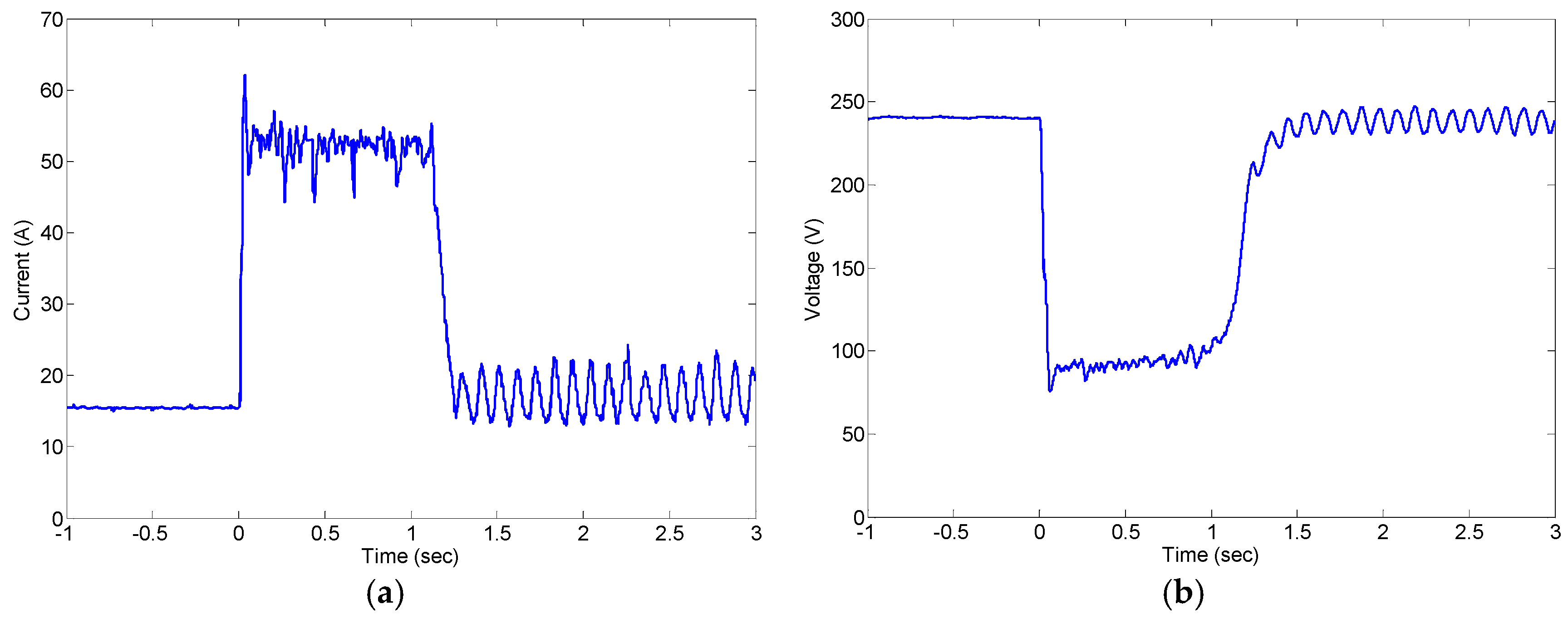
The difference between this scenario from the previous one is that the STS is switched off and the load bank set at 10 kW, and the micro-turbine is used to control the common AC bus voltage. Figure 13 presents the response of the REIF under short circuit fault. Due to the limitation on the amount of power that can be supplied by the DGs, the fault current (the total current seen by DGs at CB2) only reaches 50 A per phase, as shown in Figure 13a. On the other hand, Figure 13b shows that the voltage dropped down to 100 V during the fault, which is very different from the previous case. Therefore, both the current and voltage should be utilized as a reliable indication of a fault condition in islanded mode to increase the reliability.
6. Conclusions
In this paper, an REIF testbed with PVs and a micro-turbine is investigated. The behaviors of PVs and the gas micro-turbine are first studied under various grid voltage conditions. The experimental results demonstrate the stable operation of the REIF under various generation and load conditions. In grid-connection mode, the PVs and the grid supply power to the load with surplus energy fed back to the grid. In islanded mode, a micro-turbine is used to produce a high-quality voltage to sustain the normal operation of the load and to provide the external voltage source to which the PV inverters can synchronize. In addition, the responses of the REIF under the short circuit fault condition are studied, and the protection mechanisms are proposed, providing a technical guideline for the future grid where a significant amount of distributed generation systems are included.
Acknowledgments
This work is supported in part by The Hong Kong Polytechnic University under Grant 1-ZE7J.
Conflicts of Interest
The author declares no conflict of interest.
References
- Guerrero, J.M.; Blaabjerg, F.; Zhelev, T.; Hemmes, K.; Monmasson, E.; Jemei, S.; Comech, M.P.; Granadino, R.; Frau, J.I. Distributed generation: Toward a new energy paradigm. IEEE Mag. Ind. Electron. 2010, 4, 52–64. [Google Scholar] [CrossRef]
- Bacha, S.; Picault, D.; Burger, B.; Etxeberria-Otadui, I.; Martins, J. Photovoltaics in microgrids—An overview of grid integration and energy management aspects. IEEE Ind. Electron. Mag. 2015, 9, 33–46. [Google Scholar] [CrossRef]
- Office of the National Coordinator for Smart Grid Interoperability. NIST Framework and Roadmap for Smart Grid Interoperability Standards, Release 1.0; U.S. Department of Commerce: Washington, DC, USA; National Institute of Standards and Technology: Gaithersburg, MD, USA, 2010.
- Farhangi, H. The path of the smart grid. IEEE Mag. Power Energy 2010, 8, 18–28. [Google Scholar] [CrossRef]
- Andreadou, N.; Guardiola, M.O.; Fulli, G. Telecommunication technologies for smart grid projects with focus on smart metering applications. Energies 2016, 9, 375. [Google Scholar] [CrossRef]
- Li, F.; Qiao, W.; Sun, H.; Wan, H.; Wang, J.; Xia, Y.; Xu, Z.; Zhang, P. Smart transmission grid: Vision and framework. IEEE Trans. Smart Grid 2010, 1, 168–177. [Google Scholar] [CrossRef]
- Kirthiga, M.V.; Daniel, S.A.; Gurunathan, S. A methodology for transforming an existing distribution network into a sustainable autonoumous micro-grid. IEEE Trans. Sustain. Energy 2013, 4, 31–41. [Google Scholar] [CrossRef]
- Hosseinzadeh, M.; Salmasi, F.R. Robus optimal power management system for a hybrid AC/DC micro-grid. IEEE Trans. Sustain. Energy 2015, 6, 675–687. [Google Scholar] [CrossRef]
- Chandorkar, M.C.; Divan, D.M.; Adapa, R. Control of parallel connected inverters in standalone AC supply systems. IEEE Trans. Ind. Appl. 1993, 29, 136–143. [Google Scholar] [CrossRef]
- Brabandere, K.D.; Bolsens, B.; Van den Keybus, J.; Woyte, A.; Driesen, J.; Belmans, R. A voltage and frequency droop control method for parallel inverters. IEEE Trans. Power Electron. 2007, 22, 1107–1115. [Google Scholar] [CrossRef]
- Savaghebi, M.; Jalilian, A.; Vasquez, J.C.; Guerrero, J.M. Secondary control scheme for voltage unbalance compensation in an islanded droop-controlled microgrid. IEEE Trans. Smart Grid 2012, 3, 797–807. [Google Scholar] [CrossRef]
- Hwang, C.-S.; Kim, E.-S.; Kim, Y.-S. A decentralized control method for distributed generations in an islanded dc microgrid considering voltage drop compensation and durable state of charge. Energies 2016, 9, 1070. [Google Scholar]
- Salamah, A.M.; Finney, S.J.; Williams, B.W. Autonomous controller for improved dynamic performance of AC grid, parallel-connected, single-phase inverters. IET Gener. Trnasm. Distrib. 2008, 2, 209–218. [Google Scholar] [CrossRef]
- Vásquez, J.C.; Guerrero, J.M.; Luna, A.; Rodríguez, P.; Teodorescu, R. Adaptive droop control applied to voltage-source inverter operating in grid-connected and islanded modes. IEEE Trans. Ind. Electron. 2009, 56, 4088–4096. [Google Scholar] [CrossRef]
- Guerrero, J.M.; Hang, L.; Uceda, J. Control strategy for flexible microgrid based on parallel line-interactive UPS systems. IEEE Trans. Ind. Electron. 2009, 56, 726–736. [Google Scholar] [CrossRef]
- Li, Y.; Kao, C.N. An accurate power control strategy for power-electronics-interfaced distributed generation units operating in a low-voltage multibus microgrid. IEEE Trans. Power Electron. 2009, 24, 2977–2988. [Google Scholar]
- Hu, J.; Zhu, J.; Dorrell, D.G.; Guerrero, J.M. Virtual flux droop method—A new control strategy of inverters in microgrids. IEEE Trans. Power Electron. 2014, 29, 4704–4711. [Google Scholar] [CrossRef]
- Majumder, R.; Chaudhuri, B.; Ghosh, A.; Majumder, R.; Ledwich, G.; Zare, F. Improvement of stability and load sharing in an autonomous microgrid using supplementary droop control loop. IEEE Trans. Power Syst. 2010, 25, 796–808. [Google Scholar] [CrossRef]
- Katiraei, F.; Iravani, M.R. Power management strategies for a microgrid with multiple distributed generation units. IEEE Trans. Power Syst. 2006, 21, 1821–1831. [Google Scholar] [CrossRef]
- Ross, M.; Abbey, C.; Bouffard, F.; Joos, G. Multiobjective optimization dispatch for microgrids with a high penetration of renewable generation. IEEE Trans. Sustain. Energy 2015, 6, 1306–1314. [Google Scholar] [CrossRef]
- Valenciaga, F.; Puleston, P. Supervisor control for a stand-alone hybrid generation system using wind and photovoltaic energy. IEEE Trans. Energy Convers. 2005, 20, 398–405. [Google Scholar] [CrossRef]
- Kanchev, H.; Lu, D.; Colas, F.; Lazarov, V.; Francois, B. Energy management and operational planning of a microgrid with a PV-based active generator for smart grid applications. IEEE Trans. Ind. Electron. 2011, 58, 4583–4592. [Google Scholar] [CrossRef]
- Lasseter, R.H.; Eto, J.H.; Schenkman, B.; Stevens, J.; Vollkommer, H.; Klapp, D.; Linton, E.; Hurtado, H.; Roy, J. CERTS microgrid laboratory test bed. IEEE Trans. Power Deliv. 2011, 26, 325–332. [Google Scholar] [CrossRef]
- Bhandari, B.; Lee, K.T.; Lee, C.S.; Song, C.K.; Maskey, R.K.; Ahn, S.H. A novel off-grid hybrid power system comprised of solar photovoltaic, wind, and hydro energy sources. Appl. Energy 2014, 133, 236–242. [Google Scholar] [CrossRef]
- Proietti, S.; Sdringola, P.; Castellani, F.; Astolfi, D.; Vuillermoz, E. On the contribution of renewable energies for feeding a high altitude smart mini grid. Appl. Energy 2017, 185, 1694–1701. [Google Scholar] [CrossRef]
- Saponara, S.; Bacchillone, T. Network architecture, security issues, and hardware implementation of a home area network for smart grid. J. Comput. Netw. Commun. 2012, 2012, 534512. [Google Scholar] [CrossRef]
- Calderaro, V.; Galdi, V.; Piccolo, A. A petri net based protection monitoring system for distribution networks with distributed generation. Electr. Power Syst. Res. 2009, 79, 1300–1307. [Google Scholar] [CrossRef]
- Loix, T.; Wijnhoven, T.; Deconinck, G. Protection of microgrids with a high penetration of inverter-coupled energy sources. In Proceedings of the IEEE PES/CIGRE Symposium, Integration of Wide-Scale Renewable Resources Into the Power Delivery System, Calgary, AB, Canada, 29–31 July 2009; pp. 1–6. [Google Scholar]
- Saponara, S. Distributed measuring system for predictive diagnosis of uninterruptible power supplies in safety-critical applications. Energies 2016, 9, 327. [Google Scholar] [CrossRef]
- Saponara, S.; Fanucci, L.; Bernardo, F.; Falciani, A. Predictive diagnosis of high-power transformer faults by networking vibration measuring nodes with integrated signal processing. IEEE Trans. Instrum. Meas. 2016, 65, 1749–1760. [Google Scholar] [CrossRef]
- Costantino, N.; Serventti, R.; Tinfena, F.; D’Abramo, P.; Chassard, P.; Tisserand, P.; Saponara, S.; Fanucci, L. Design and test of an HV-CMOS intelligent power switch with integrated protections and self-diagnostic for harsh automotive applications. IEEE Trans. Ind. Electron. 2011, 58, 2715–2727. [Google Scholar] [CrossRef]
- IEEE Standard for Interconnecting Distributed Resources with Electric Power System; IEEE Standard 1547; IEEE: New York, NY, USA, 2003.
Figure 1.
The laboratory renewable energy integration facility (REIF) under study. PV: photovoltaic.
Figure 1.
The laboratory renewable energy integration facility (REIF) under study. PV: photovoltaic.
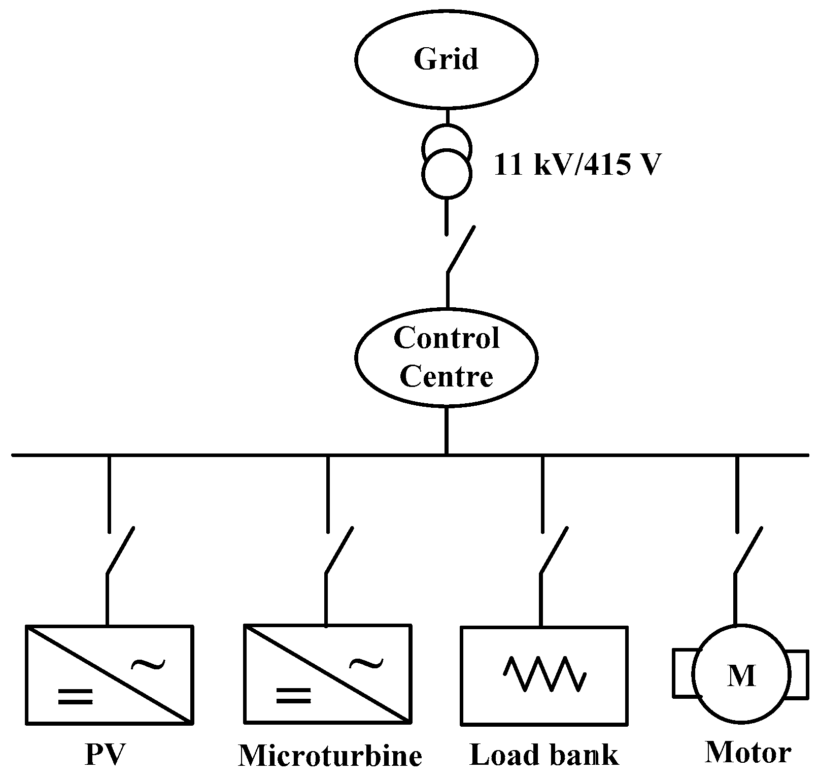
Figure 2.
Total output power of the PV system on two different days.

Figure 3.
Response of one PV inverter to the loss of external grid power.
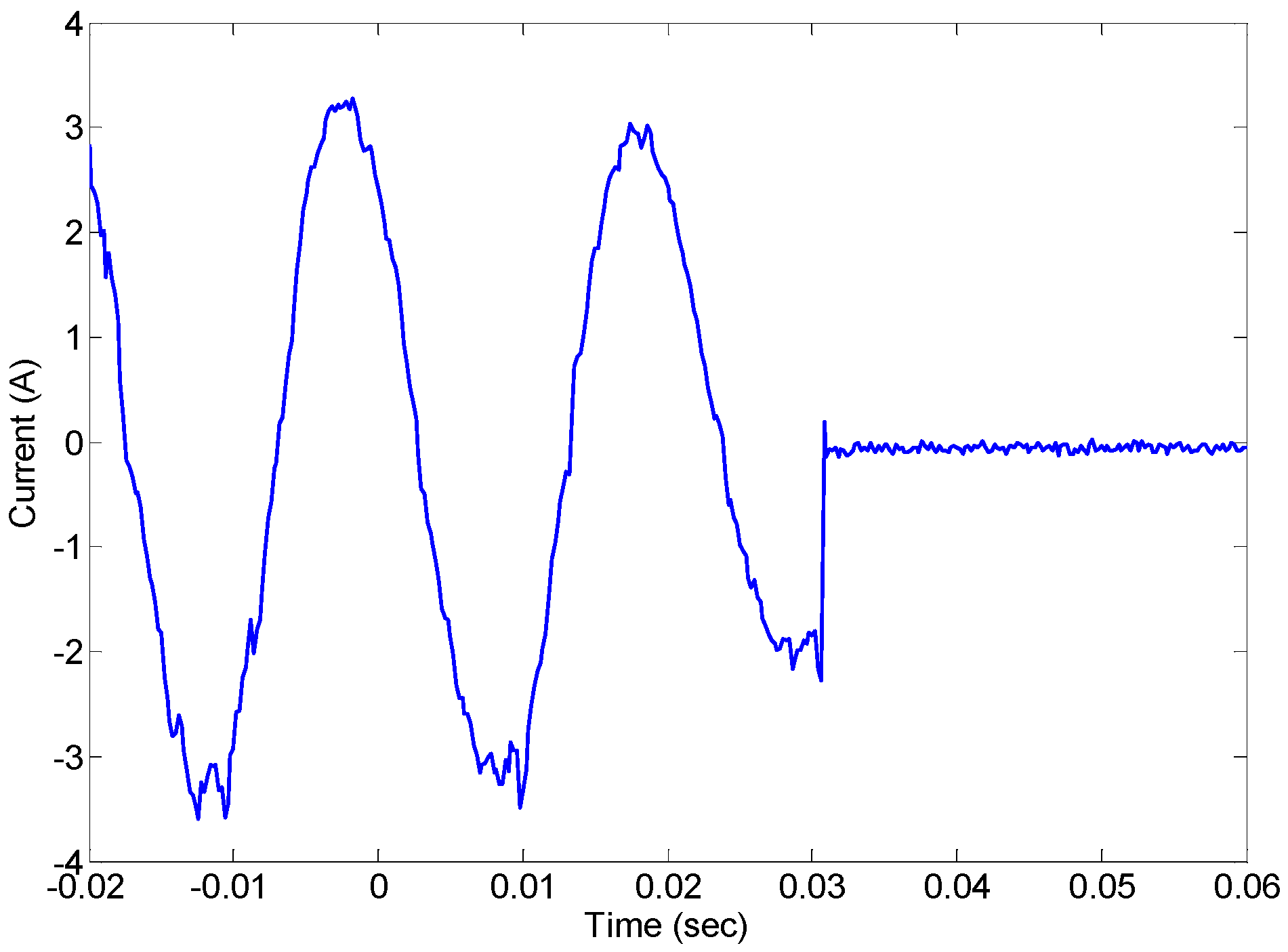
Figure 4.
Response of the three-phase PV output currents to the loss of external grid power.

Figure 5.
Response of the PV inverter output power to frequency variation.

Figure 6.
Response of the PV inverter output current to voltage disturbance.

Figure 7.
Coordinated operations of the REIF. STS: static transfer switch.

Figure 8.
System performance in grid-tied mode. (a) Power flow; and (b) point of common coupling (PCC) voltage.
Figure 8.
System performance in grid-tied mode. (a) Power flow; and (b) point of common coupling (PCC) voltage.

Figure 9.
System performance in islanded mode. (a) Active and reactive power sharing; (b) micro-turbine output current during load changes; and (c) PCC voltage.
Figure 9.
System performance in islanded mode. (a) Active and reactive power sharing; (b) micro-turbine output current during load changes; and (c) PCC voltage.

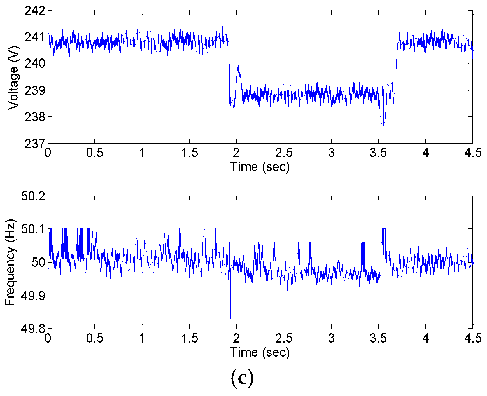
Figure 10.
Harmonic spectrum of the common AC bus voltage. (a) Grid-tied operation; and (b) stand-alone operation.
Figure 10.
Harmonic spectrum of the common AC bus voltage. (a) Grid-tied operation; and (b) stand-alone operation.

Figure 11.
Conceptual diagram of faults in a microgrid. CB: Circuit breaker.

Figure 12.
Response of current and voltage during a fault in grid-connected mode (a) currents; and (b) common AC bus voltage (PCC voltage).
Figure 12.
Response of current and voltage during a fault in grid-connected mode (a) currents; and (b) common AC bus voltage (PCC voltage).

Figure 13.
Voltage and current response to the fault in islanded mode (a) current at circuit CB2; and (b) common AC bus voltage.
Figure 13.
Voltage and current response to the fault in islanded mode (a) current at circuit CB2; and (b) common AC bus voltage.

Table 1.
Power quality comparison.
| Performance | Voltage Distortion (%) | Flicker |
|---|---|---|
| IEEE 1547 | 5.0 | 0.8 |
| Grid-tied mode | 1.40 | 0.12 |
| Stand-alone mode | 2.31 | 0.56 |
© 2017 by the author. Licensee MDPI, Basel, Switzerland. This article is an open access article distributed under the terms and conditions of the Creative Commons Attribution (CC BY) license (http://creativecommons.org/licenses/by/4.0/).
Share and Cite
MDPI and ACS Style
Hu, J. Coordinated Control and Fault Protection Investigation of a Renewable Energy Integration Facility with Solar PVs and a Micro-Turbine. Energies 2017, 10, 423. https://doi.org/10.3390/en10040423
AMA Style
Hu J. Coordinated Control and Fault Protection Investigation of a Renewable Energy Integration Facility with Solar PVs and a Micro-Turbine. Energies. 2017; 10(4):423. https://doi.org/10.3390/en10040423
Chicago/Turabian StyleHu, Jiefeng. 2017. "Coordinated Control and Fault Protection Investigation of a Renewable Energy Integration Facility with Solar PVs and a Micro-Turbine" Energies 10, no. 4: 423. https://doi.org/10.3390/en10040423
Note that from the first issue of 2016, this journal uses article numbers instead of page numbers. See further details here.