1. Introduction
Gerotor pump technology is being increasingly employed in innovative application fields, such as life science (pharmaceutical, medical and biotechnology) where its presence was unusual not many years ago. This remarkable growth is based on its three main advantages: simplicity, versatility and performance. These developing sectors present challenges for additional applications, introducing a demanding for pumps that can improve energy-efficiency by controlling the volumetric flow rate without wastefully throttling or bleeding-off.
Variable displacement pumps are widely used in hydraulic systems but they can be high-cost, high-performance, and are a very expensive unit for common consumer functions. They are not suitable for much lower-cost applications, and there are new concepts of variable gerotor pumps that do not bleed off the delivered flow [
1]. Moreover, hydraulic systems pumps are usually fixed-displacement units and generally incorporate a flow control valve, which bleeds off excess flow, resulting in poor performance efficiency.
Finally, recent standards, such as environmental concerns, are leading to leakage-free and more silent units. The primary source of noise in a hydraulic system is the inherent noise of the pump, which depends on pressure pulsations and rotational speed, eventually emitted as air-borne sound.
In reviewing the current state of the research field of hydraulic gear machines, a great amount of work has been published, especially the reference book by Ivantysyn and Ivantysynova [
2]. In the present article, the authors concentrate on the most recent open literature of the last three years, owing to the continuous and rapid evolution of this research field.
The key publications in this period are mainly dedicated to lubrication, deformation and leakage performance, among others, in an external gear pump [
3], crescent pump [
4] and combination of external gear pump and gerotor pump [
5].
The new progressive topics related to gerotor pumps are mainly numerical approaches corroborated with experimental work. The most recent published works are Frosina et al. [
6,
7] and Buono et al. [
8], devoted to the analysis of geometric influence of a lubrication gerotor pump, validated with experimental pressure oscillations, and Pellegri et al. [
9,
10], which compares how their two numerical approaches can match experimental results under proper assumptions. The work presented by Altare and Rundo [
11] is an improvement in the operational understanding of a gerotor pump through an extensive analysis of the influence of the thickness and the diameter of the gears, the position of the inlet pipe with respect to the rotors and the shape of the port plate in its suction capability. Garcia-Vilchez et al. [
12] introduce a non-invasive visualization technique to validate the numerical results in a gerotor pump.
Other key publications are related to reducing contact stress by new variable clearance strategies that diminish collisions [
13] by changing geometric parameters of the trochoidal gearing teeth profile [
14] and by using new materials for the gear set [
15].
Nevertheless, despite there being a commendable combination of numerical methods to guide the designer in an early stage of the design process of a gerotor pump, the review of the literature reveals a lack of work devoted to design analysis of new-born, not-yet-constructed, gerotor pumps. The consulted literature discloses that gerotor studies are mainly numerical simulations corroborated with experimental validation in existing units, especially projects in collaboration with the industrial manufacturer of the pump.
Taking into consideration the qualities of gerotor pumps and the challenges faced in emergent sectors, as well as more demanding standards and concerns, GeroMAG was developed as a new concept of gerotor pump through to the final stage of the design process: a prototype. Here, the main goal of the GeroMAG pump is to accomplish a standard volumetric flow rate at low rotational speed with satisfactory volumetric efficiency, and consequently a quieter unit, together with being leakage-free (sealed and non-shaft drive) and reducing air-borne noise (compact without exterior shaft driving). The GeroMAG pump, as a variable-flow pump operating at low pressures and powered by a quiet magnet brushless motor, will find application, among others, in small mobile power packs and domestic applications such as passenger and parking lifts, that could be operated all day even at night thanks to the GeroMAG development.
To the authors’ knowledge, such a proposition has not been presented as a proof of concept, and its viability has not yet been proven. The principal conclusion is that the GeroMAG concept and pump prototype are feasible. Experimental results and performance indexes corroborate it.
2. GeroMAG Concept and Pump Prototype
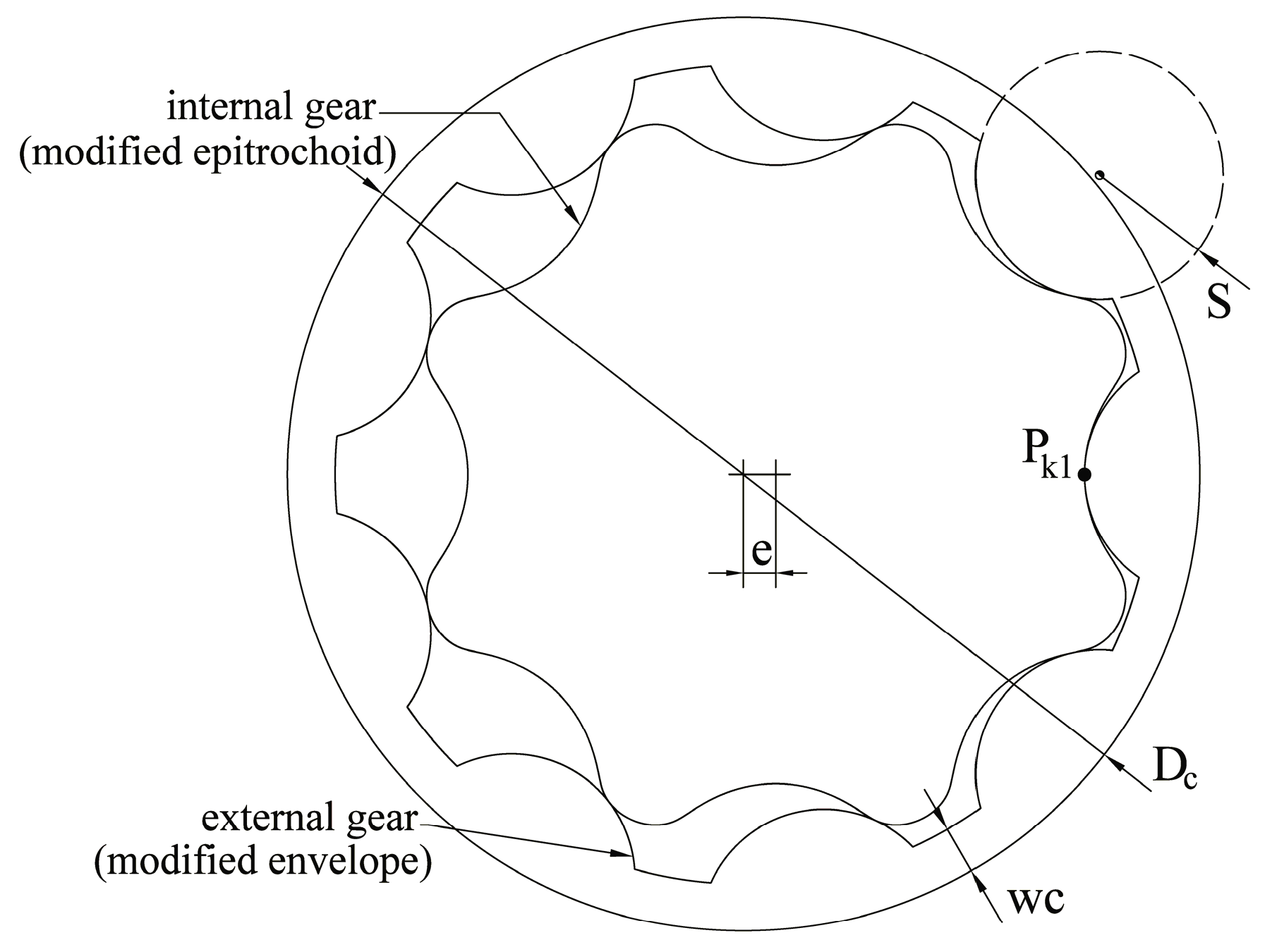
Basically, a gerotor pump is an internal gear pump of a pair of gears with trochoidal tooth profiles: an inner/internal gear and an outer/external gears (see
Figure 1). The two gears are mated so that each tooth of the internal gear is always in sliding contact with a tooth of the external gear, and inter-tooth contact occurs. These points are known as contact points.
2.1. Designing the Trochoidal-Gear Unit
An extensive study of available trochoidal gear sets by means of commercial literature shows a large number of standard trochoidal gear sets, and each application has to be adapted to fit one of them. However, the selection of the design parameters that has led to the geometry of these standard trochoidal gear sets is not clear, at least in the available information sheets. Despite being the cost-effective solution, it is advisable to choose design parameters that allow the correct balance between contact stress, volumetric characteristics and flow irregularity to be achieved.
As a result, a custom trochoidal gear set is developed from scratch in this work, by following the authors’ catalogue of best-practice rules [
16]. The research behind this custom trochoidal gear set is intended to provide the optimal solution for given dimensional constraints and to evaluate the performance of the first design in achieving the volumetric characteristics.
The characterization of the system at low rotational speed implies a standard volumetric flow rate and, as a consequence, the volumetric capacity
cv in [cm
3/rev]. Then, the dimensional constraints set up the trochoidal gear thickness
H in [mm] and the external diameter of external gear
Dc in [mm] (see
Figure 1 and
Table 1). These dimensional constraints are chosen to accomplish the configuration of the innovative magnetic drive arrangement.
Then, the eccentricity
e in [mm] of the trochoidal gear set, which is the most difficult geometrical parameter to predict, can be calculated by using a heuristic approach to the equation,
where
wc in [mm] is the wall width of the external gear (see
Figure 1). The value of
wc can be estimated by using the following expression,
being just an estimation because it does not take into account the number of teeth of the external gear, working pressure, contact stress or gear material. Now, the arc radius of the external gear tooth
S in [mm] can be calculated as:
where
Z is the number of teeth of the external gear and
λ is the tooth profile height correction coefficient—a function of the eccentricity, the number of teeth, the arc radius of the outer gear tooth and the tip diameter of the internal gear—with recommended values going from 0.6 (larger
S) to 0.8 (shorter
S) [
15].
Finally, the theoretical outputs such as the theoretical torque
T in [N·m/bar], theoretical power
N in [W/bar·rpm], the tip velocity of the internal gear
Vt in [m/s·rpm], and the theoretical radial load
RL in [N/bar] can be estimated by using the following expressions:
The values obtained for the GeroMAG trochoidal gear set are summarized in
Table 1.
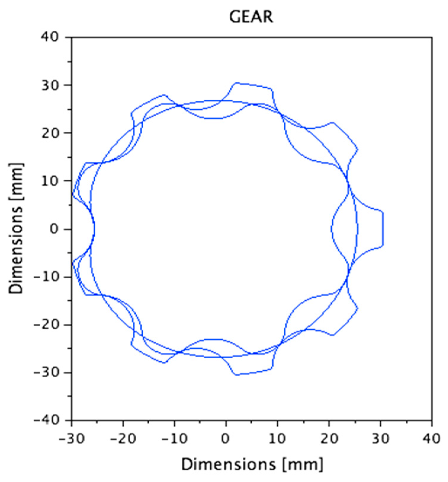
2.2. Modeling the Trochoidal-Gear Unit
Once basic geometrical parameters are defined, the well-known formulae for calculating the trochoidal profiles of the internal gear are used. In addition, these parameters can be introduced in specialized free software, such as GeroLAB [
17], which will calculate and provide the technical drawings in CAD format (see
Figure 2).
2.3. Conception of the Magnetically-Driving Outer Rotor
The trochoidal gear set of a gerotor pump is mated so that each tooth of the internal gear is always in sliding contact with a tooth of the external gear. Both gears rotate in the same direction but at different speeds because the external gear has one tooth more than the internal gear, and consequently, the internal gear is slightly faster than the external gear.
The process of pumping is carried out when the rotational movement of the gear set creates circulation of increasing volume between consecutive contact points from the inlet to the outlet port of the pump.
To date, rotational movement in the standard gerotor pump technology has been transmitted from the internal gear (driving) to the external gear (driven) by means of an exterior drive shaft motor. Moreover, the external gear rotation is guided into the interior of the pump housing in continuous sliding contact with its external wall, named external sideway, of perimeter πDc and thickness H.
GeroMAG represents a step forward in the gerotor pump concept: the magnetically-driving outer rotor. This new concept is based on:
- (1)
Driving outer rotor. The external gear is the driving gear named driving outer rotor. Consequently, in this innovative configuration, the rotational movement is transmitted from the driving outer rotor to the driven internal gear.
- (2)
Non-shaft. There is neither mechanical drive shaft nor exterior drive shaft.
GeroMAG confronts, then, two main technological challenges: (i) how to generate the rotational movement of the driving outer rotor in the gerotor pump; and (ii) how to produce the guide of rotation of the gear set once the external sideway of the outer rotor, the external wall of perimeter πDc and thickness H, cannot be used.
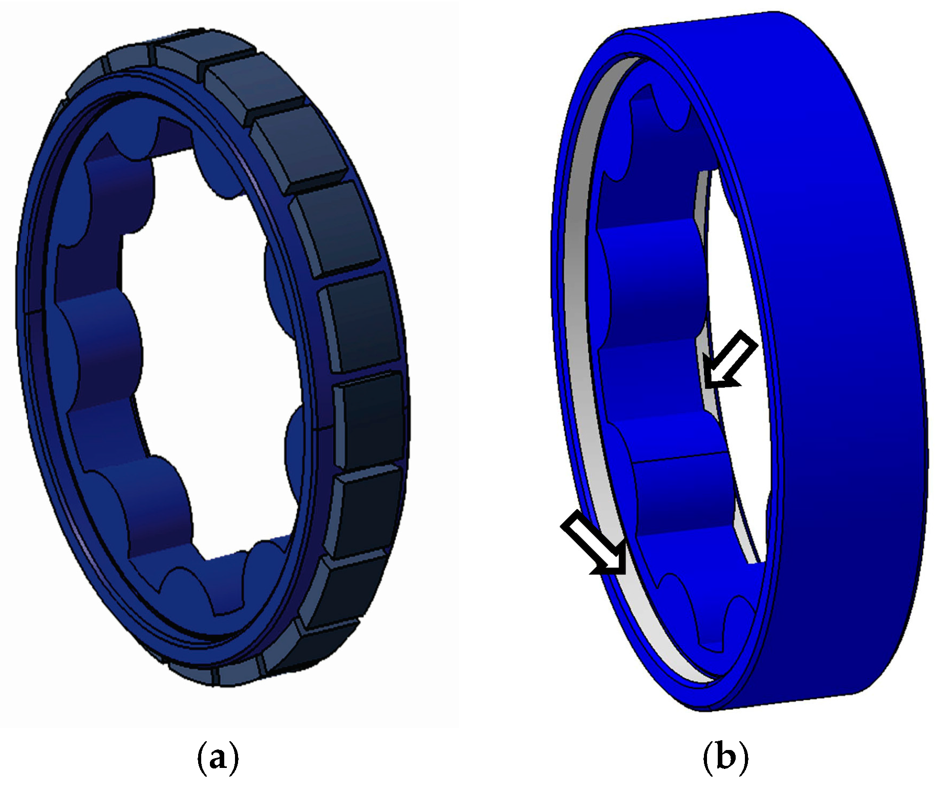
2.3.1. Outer Rotor Rotated by Electro-Magnetic Driving
Without mechanical shaft-driving, the external gear takes the role of primary pump gear conducting the rotational movement as a driving outer rotor. Without an exterior drive shaft, using electro-magnetic driving on the outer rotor provides the indispensable torque for the rotational movement. Pole pieces, depicted in
Figure 3a, are fixed to the external sideway of the outer rotor and the magnetic field generated by the stator ring with electric coils will provide the required torque. There is never sliding contact between pole pieces and the stator ring. Instead, an extraordinarily narrow magnet gap is formed and is eventually filled with working fluid.
2.3.2. Outer Rotor Guided by the Inner Edgewise Pad
The coaxiality of each gear in its own rotation center, as well as the eccentricity of internal gear and outer rotor have to be guaranteed. In the standard gerotor pump technology, they are guaranteed by the mechanical shaft-driving connected to the internal gear and by the external sideway of the external gear. However, in the GeroMAG configuration, the pole pieces fixed to the external sideway of the outer rotor cannot be in continuous sliding contact with the stator ring. The stator ring does not accomplish, among other things, the tolerances and material required to ensure the operational mechanism. Consequently, the external sideway of the outer rotor cannot guide the rotation movement of the gear set.
Therefore, a new concept and design of the outer gear named the inner edgewise pad is presented. As shown in
Figure 3b, a guiding internal surface, opposite to the external sideway, is now used to guide the rotational movement of the outer gear. The guide is performed by the path of the inner surface on both sides of the outer gear teeth faces. This has been named inner edgewise pad by the authors. To complete the guide of the gear set, a stationary shaft that is part of the pump body sets the rotation center of the internal gear.
Moreover, in order to avoid having metal-to-metal in continuous sliding contact, the outer rotor has to operate with hydrodynamic film supporting the outer rotor and faces. Then, the inner edgewise pad is designed to perform a full film lubrication with hydrodynamic film at all times of operation.
2.4. GeroMAG Pump Architecture
The GeroMAG pump architecture embodies, as previously described, the internal gear, the magnetically-driving outer rotor and the stator ring. The configuration of the GeroMAG pump does not just have to accommodate the magnetically-driving outer rotor arrangement, but also be compact, non-mechanically shaft-driving and sealed without an exterior drive shaft. The technology development in this preliminary design has to conclude with a technology demonstration by means of a prototype in lab testing in an experimental test bench.
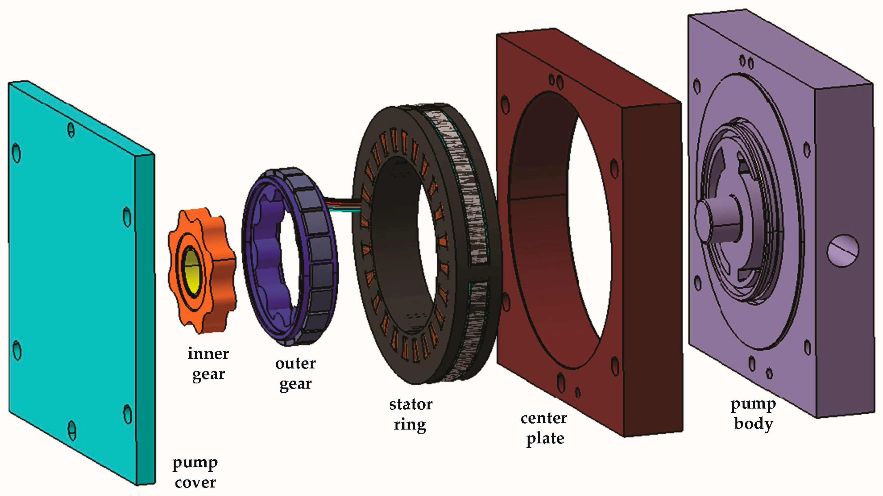
Then, as shown in
Figure 4, the pump construction is an ensemble with three more elements: the pump body, the center plate and the pump cover completing the GeroMAG pump architecture. The pump body includes the inlet and outlet ports, as well as the metering porting with grooves as an important factor to volumetric performance and efficiency. The depth of the porting is such that it does not restrict the pump flow.
The center plate houses the stator ring, becoming a hermetic set since the whole interior of the pump is filled and wet with working fluid. Thus, the pump cover closes and seals the ensemble. A light version of the porting, the shadow porting, is carved on the pump cover to help axial pressure balance, preventing unwanted thrust loads and helping to fill the chambers from both lateral sides creating a double filling.
There is a guiding cylinder milled in the pump body as a stationary shaft, because it does not rotate. Likewise, to guide the inner edgewise pad of the outer rotor, the pump cover and pump body have been milled, with each guiding cylinder performing a full film lubrication at all times of operation. It is important to point out that the GeroMAG design does not include any particular seal for static or dynamic sealing.
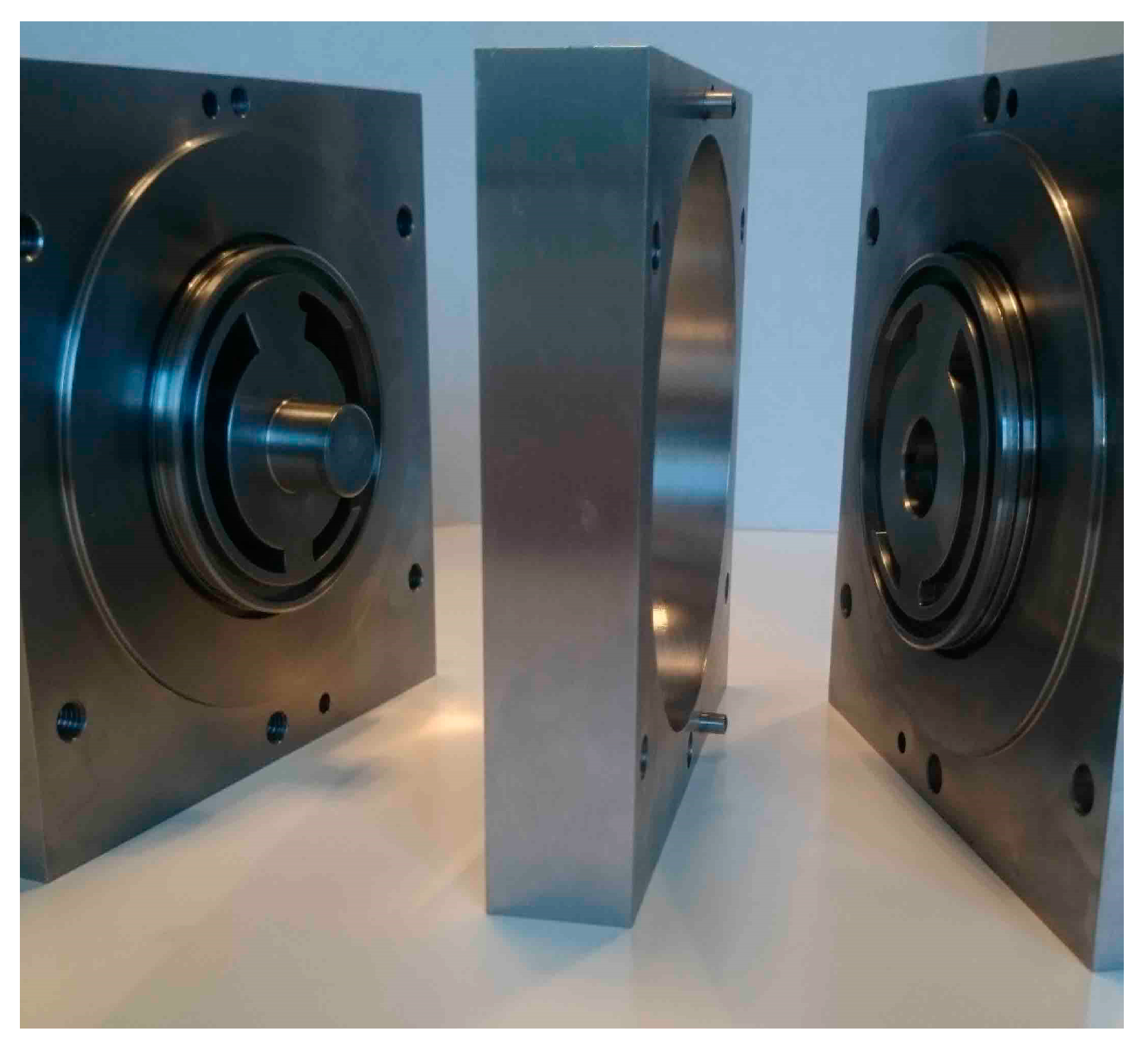
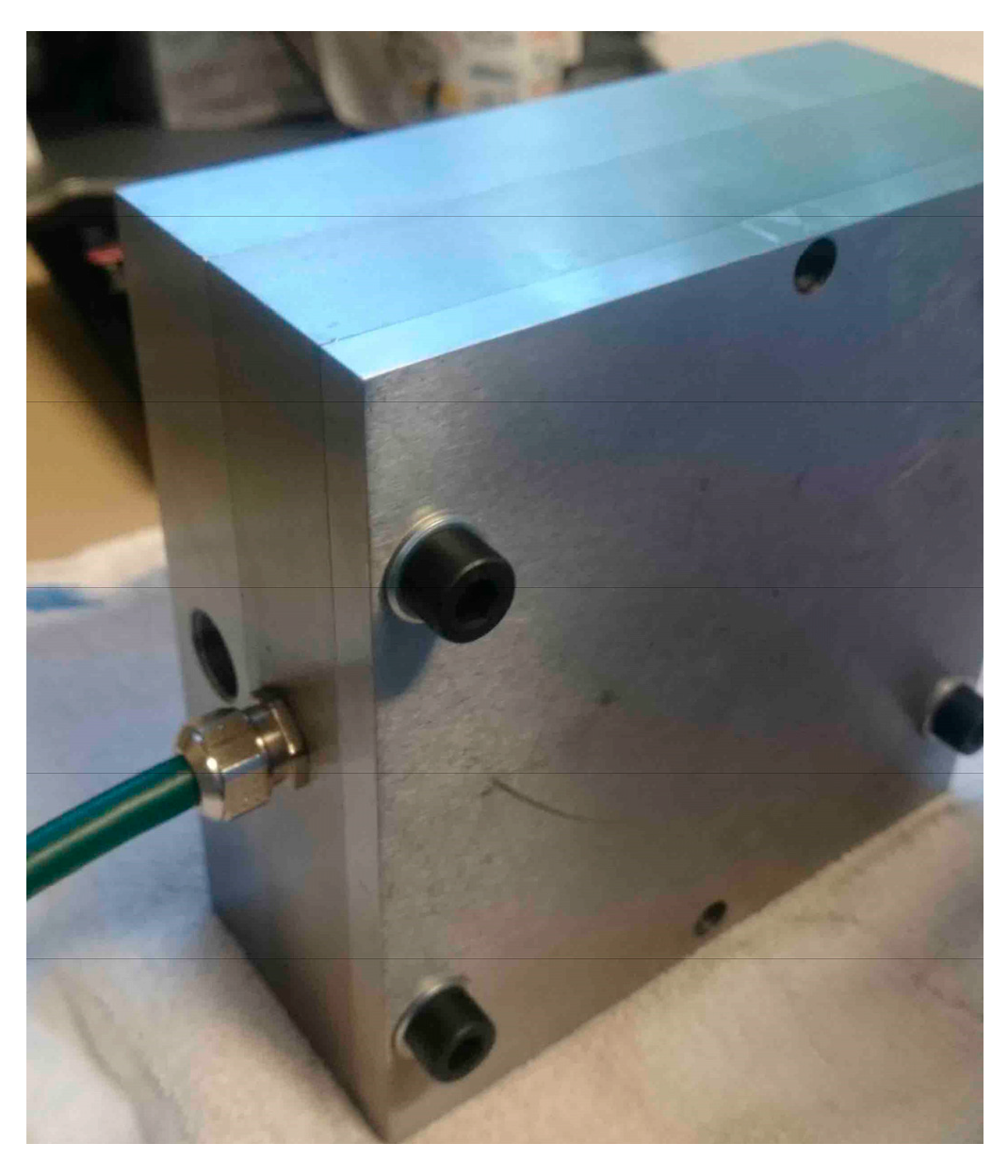
Each of the three elements, pump body, center plate and pump cover, has been manufactured by an expert mechanical workshop, a specialized manufacturing center, with high precision, tolerance control and fine surface finishing, as shown in
Figure 5.
The material of the three elements is the same: steel of high quality. In this first prototype, in spite of the total set weight, surface roughness and tolerance accuracy, as well as temperature effects were tightly controlled during the manufacturing process. In a future step, the material of a second prototype will be aluminum, or similar alloy to be studied, reducing weight.
2.5. Materials and Manufacture of the Trochoidal Gear Set
The trochoidal gear set, shown in
Figure 6, has been manufactured by AMES from blanks of sintered metal material because it is believed to be the most appropriate technology for these types of components. The FD-05N2C-400 was chosen as the powder metallurgical material, following requirements and specifications of the standard ISO 5755:2012, owing to its combination of hardness (180 HV5) and mechanical strength (590 MPa).
The generation of the trochoidal gear profiles has been carried out with wire electrical discharge machining, wire-cut EDM. The rest of the geometry was carried out with a Computer Numerical Control (CNC) cylindrical grinding machine.
In order to obtain an accurate and correct rotation of the gear set, the trochoidal profiles have a tolerance grade of IT7 achieving tip clearance from 21 to 90 μm. The precision in the gear thickness is 10 μm and the surface roughness is 0.1 Ra.
The dimensional controls were performed using a high accuracy CNC coordinate measuring machine. The trochoidal profile examination was carried out with a high-precision rotation inspection instrument and the gear-set surface roughness and contour measurement with formtracer and metrology software.
2.6. MGB-2 Magnet Brushless Motor
The electrical motor is an ad hoc multipolar surface-mounted permanent magnet brushless motor model MGB-2 designed and manufactured by Mavilor Motors (Santa Perpetua de Mogoda, Spain) for the GeroMAG pump. The MGM-2 has deeply considered two imperative conceptions in its design. Firstly, the torque to rotate the gear set is not intended to work as a gearbox, but rather to work as part of a hydraulic pump. Secondly, the contact area arises between rotor-stator-liquid. The contact area has been minimized to improve the efficiency of the system. Both conceptions are rather opposed, as a higher torque requires larger volume, but larger volume implies more friction and has to be prevented.
The stator ring is dimensionally optimized by compacting the winding with concentric coils fully capsulated, which not only allows the working fluid to cross through the magnetic gap between pole pieces and stator, but also isolates the electrical parts from the rest of the elements of the pump.
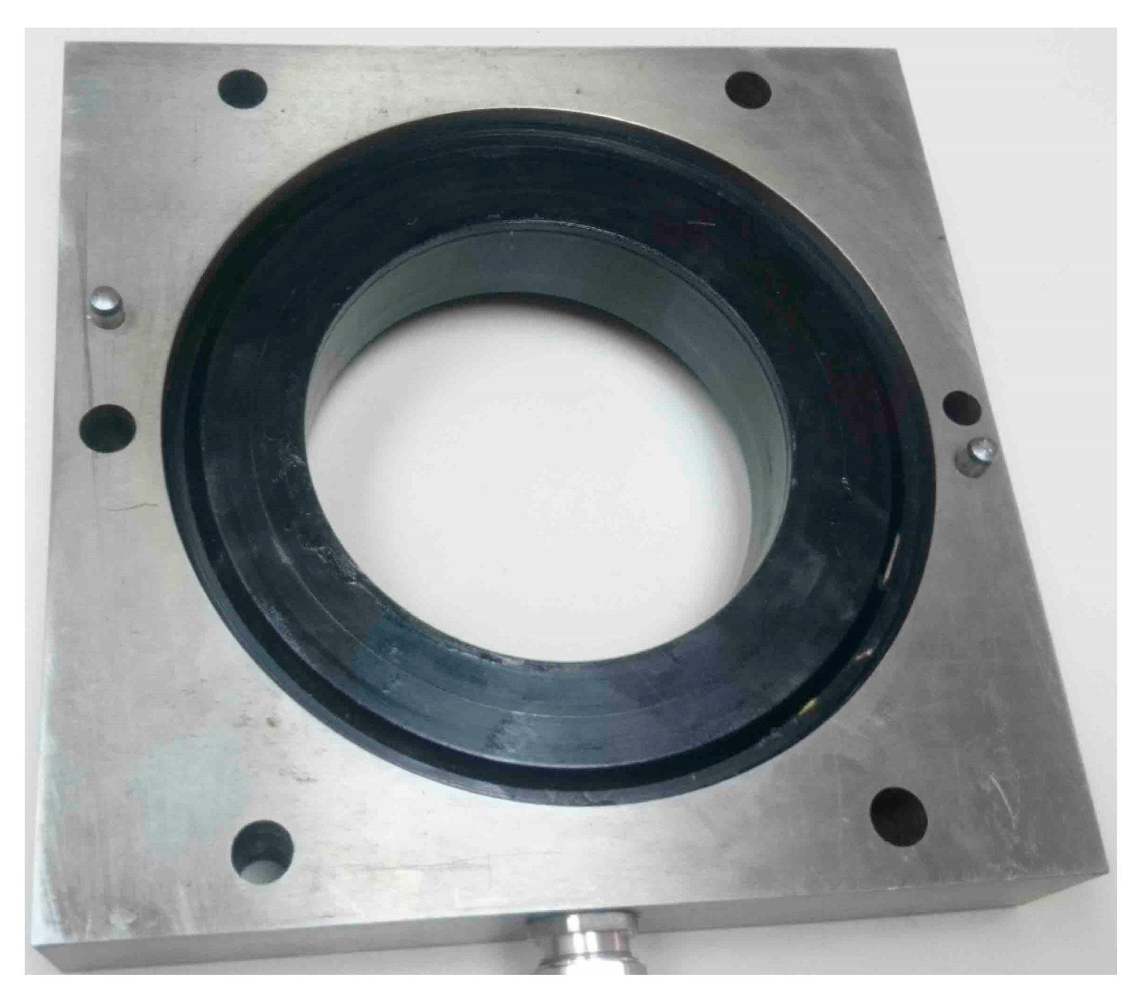
The stator ring is placed in the center plate, as shown in
Figure 7. This configuration is wholly hermetic and sealed and consequently can work immersed in and wet by the working fluid.
The MGM-2 is controlled by the sensorless drive Infranor EASY AK 230/17 + FCL EASY 230. The system is supplied for the tests with 48 Vdc and a limit current of 5 A in a continuous mode for the drive. The power is monitored with the power analyzer Circuitor CVM-C10-ITF-485-ict2. The motor specifications are summarized in
Table 2.
2.7. GeroMAG Pump Prototype
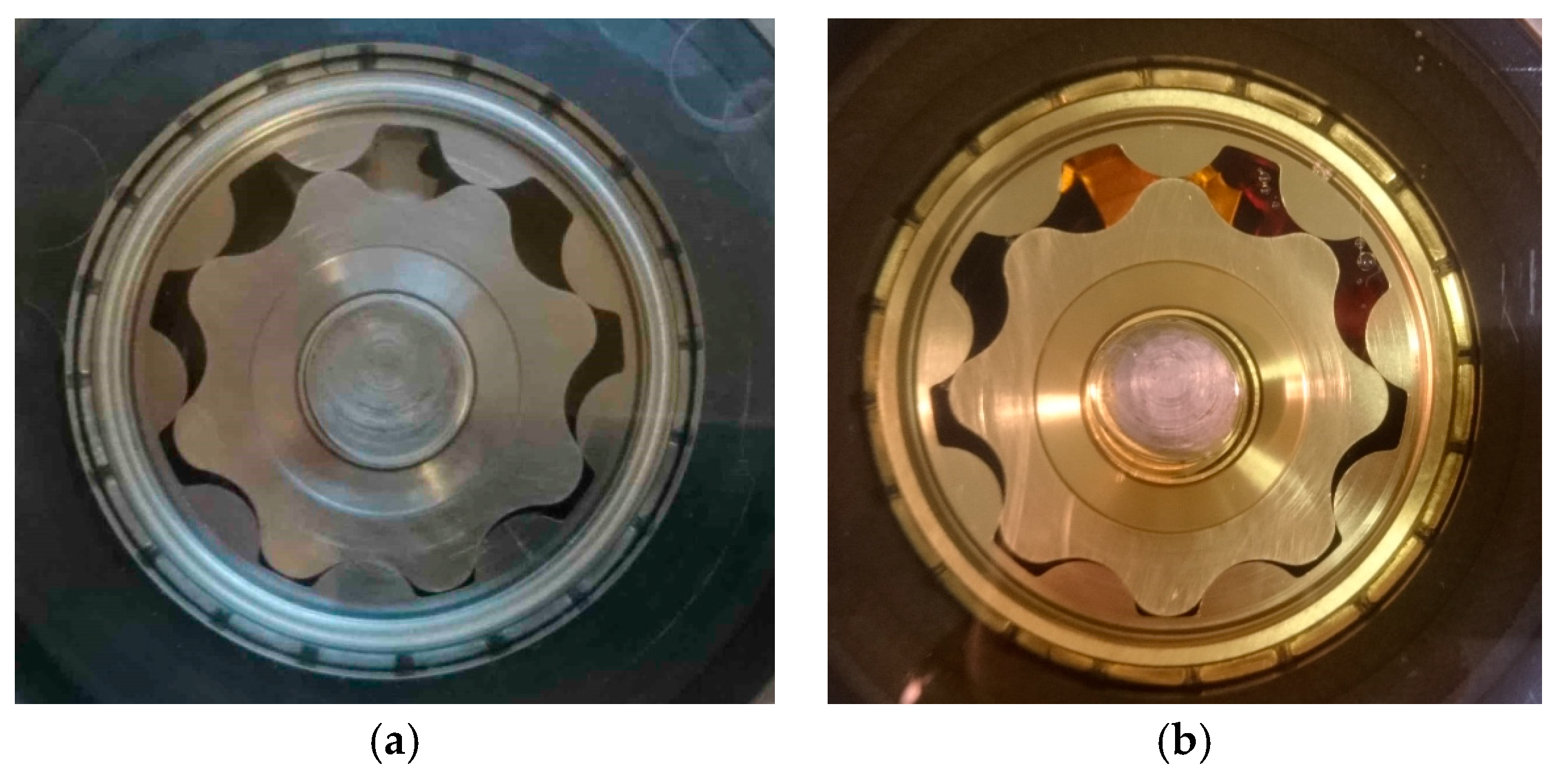
The ensemble of the GeroMAG pump prototype is shown in
Figure 8. The pump prototype is intended to be the proof of concept and technology demonstration, with lab testing on an experimental test bench. The first performance tests were carried out using a pump cover manufactured in-house with a transparent polymer. The transparent pump cover allowed the direct observation of the operation of the prototype, and also the recording of it with a high-speed video camera for slow motion analysis. Both dry and wet conditions were examined as shown in
Figure 9.
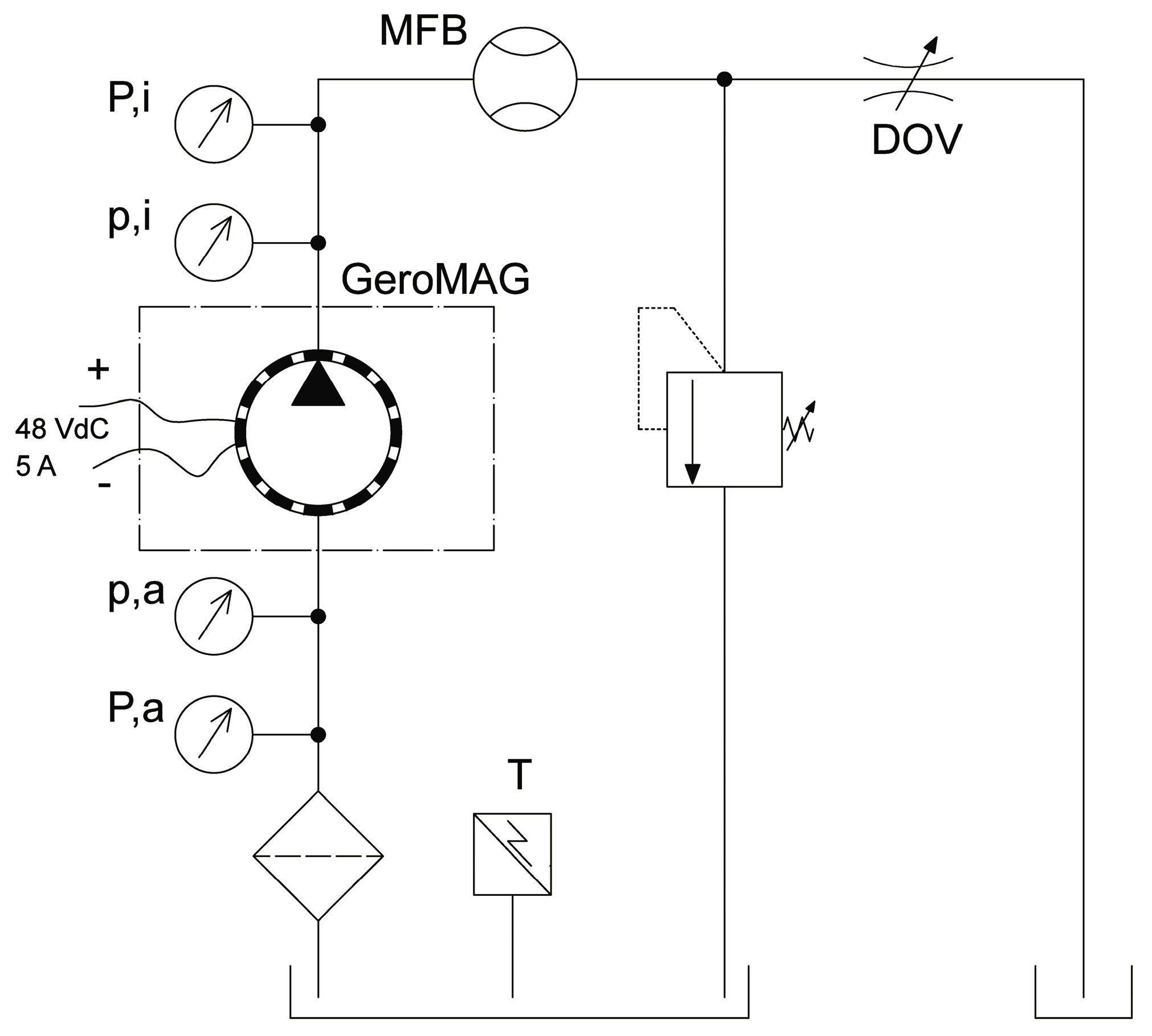
3. Experimental Procedure and Testing
The experimental work carried out with the GeroMAG pump is intended to characterize the steady-state flow-pressure performance. A test bench was set up, the hydraulic layout of which is depicted in
Figure 10.
The rotational speed of the GeroMAG pump is controlled by means of the sensorless drive. The inlet (p,a) and outlet (p,i) dynamic pressure was measured by using a PCB® piezoelectric miniature dynamic pressure sensor model 113B21 with measurement range of 0–1379 kPa bar and sensitivity of 3.6 mV/kPA. The inlet (P,a) and outlet (P,i) static pressure was measured by using a Unik® 5000 pressure transducer with measurement range of 0–2000 kPa and precision of ±0.2% FS. An acquisition system allows the control and process of the incoming pressure signals of the test bench via a National Instruments® data acquisition device NI USB-6343.
The working pressure was settled by a Wandfluh® (Wandflluh AG, Frutigen, Switzerland) manual direct operating valve (DOV). The working fluid was Hydrolubric ISO VG 32 hydraulic oil with a viscosity of 32 mm2/s at 40 °C. The experimental tests were performed at a constant temperature of 30 °C measured by using a PT100 resistance temperature detector (T) in a three-liter reservoir. The 860 kg/m3 working-fluid density was measured with a hydrometer. Before starting the experimental procedure, the working fluid was filtered at 5 μm with a Millipore® vacuum filter holder to avoid any damage to hydraulic system components.
The mass flow rate was measured by using a Kern® precision balance models PCB 3500-2 weighing range 3500 ± 0.01 g (MFB). By using serial communication RS-232C, the mass flow incoming signal was transmitted to the computer by means of the data acquisition device NI USB-6343. An ad hoc code based on LabView® (National Instruments, National Instruments, Austin, TX, USA) software allows the acquisition and process of all test bench output signals.
4. Results
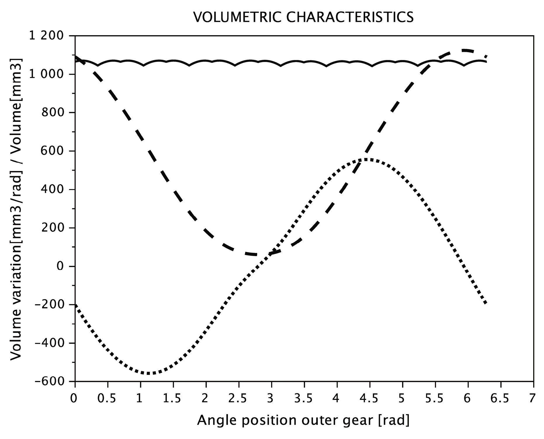
4.1. Trochoidal Gear Set Performance Indexes
The trochoidal-gear geometrical parameters are established based on analytically-simulated operating conditions. Geometrical parameters and operating conditions establish the performance indices: the volumetric characteristics (chamber volume, volume variation, instantaneous flow and irregularity flow index, as the rate between the difference of maximum-minimum volume and the average volume) and the maximum contact stress. The most influential parameters are found to be the operating pressure and the number of teeth. While the volumetric characteristics become better as the number of teeth increases, the contact stress becomes worse. Then, in order to reduce the maximum contact stress and obtain the optimal volumetric characteristics, the GeroLAB Package System is utilized [
17]. The volumetric characteristics with an irregularity flow index of 2.7% are obtained as shown in
Figure 11.
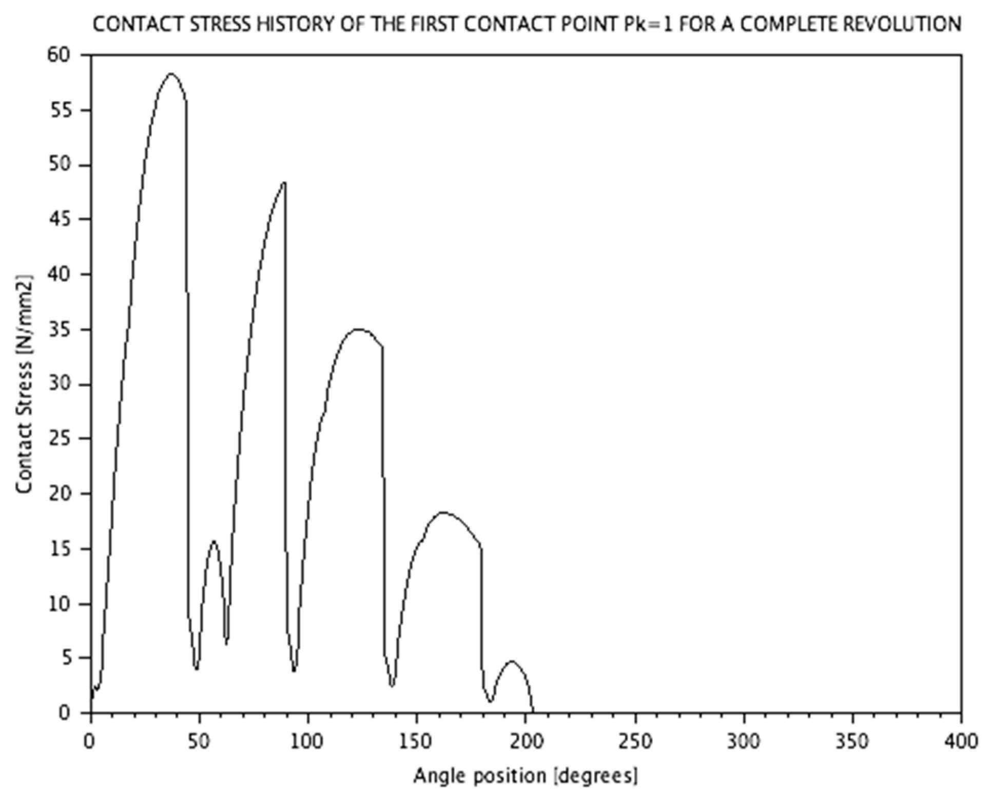
With regard to the maximum contact stress, the significant parameters are the number of teeth and the minimum radius of curvature of the internal gear. By increasing the number of teeth, its shape becomes sharper and it produces high contact forces. Moreover, not all the contact points contribute to transmitting the moment. Accordingly, and taking a counter-clockwise rotation as a reference, the contact points (
Z + 1)/2 will transmit the stress moment from the outer to the inner gear owing to the fact that they are active points. Thus, when a couple is applied to the gear, it will rotate a small amount about its axis, until the tooth deformations are large enough to provide forces whose combined moments are equal to the stress moment.
Figure 12 shows the maximum contact stress history of the first contact point (P
k1 in
Figure 1) for a complete revolution of the outer gear at maximum working pressure of 0.5 MPa.
4.2. GeroMAG Pump Prototype Performance Indices
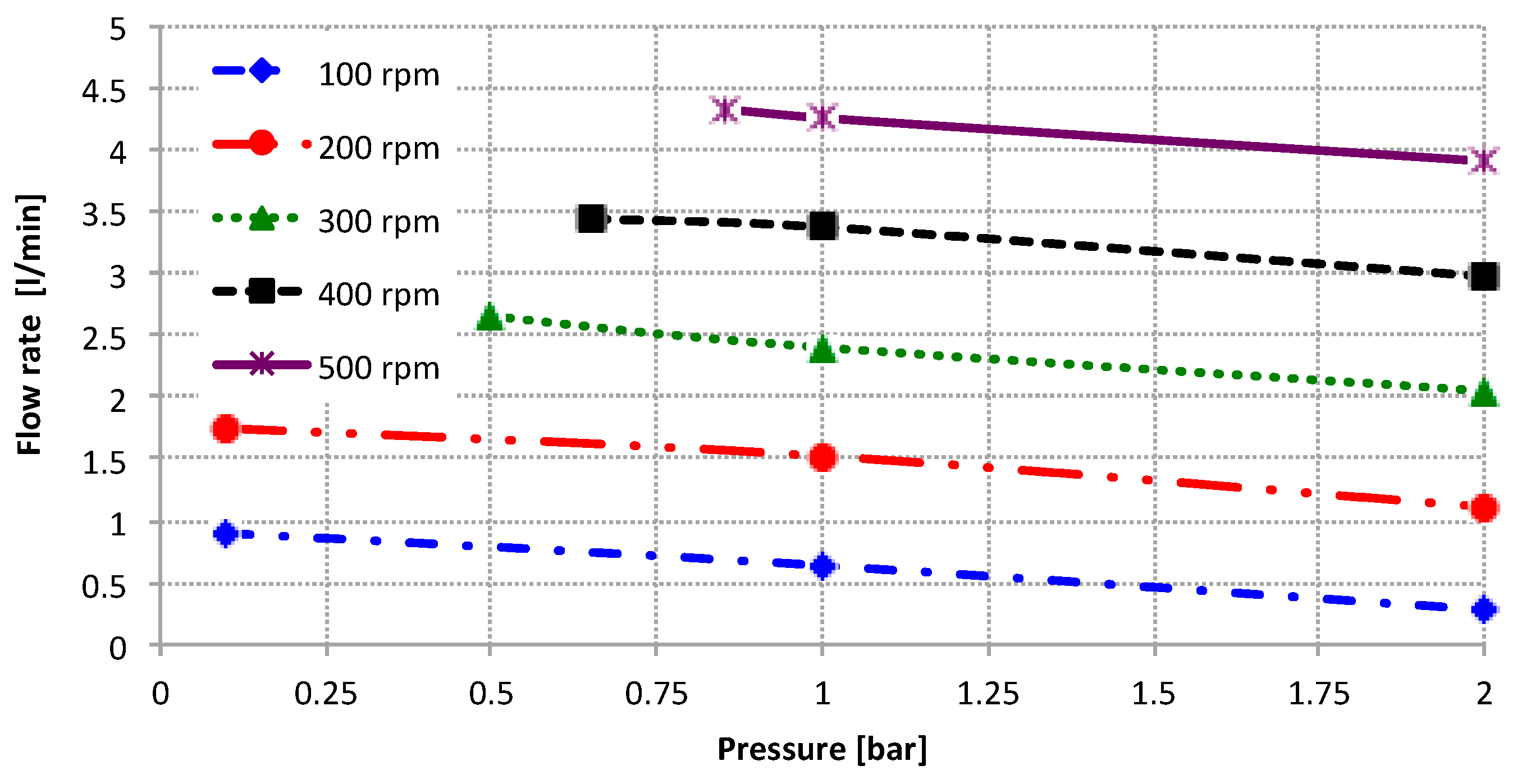
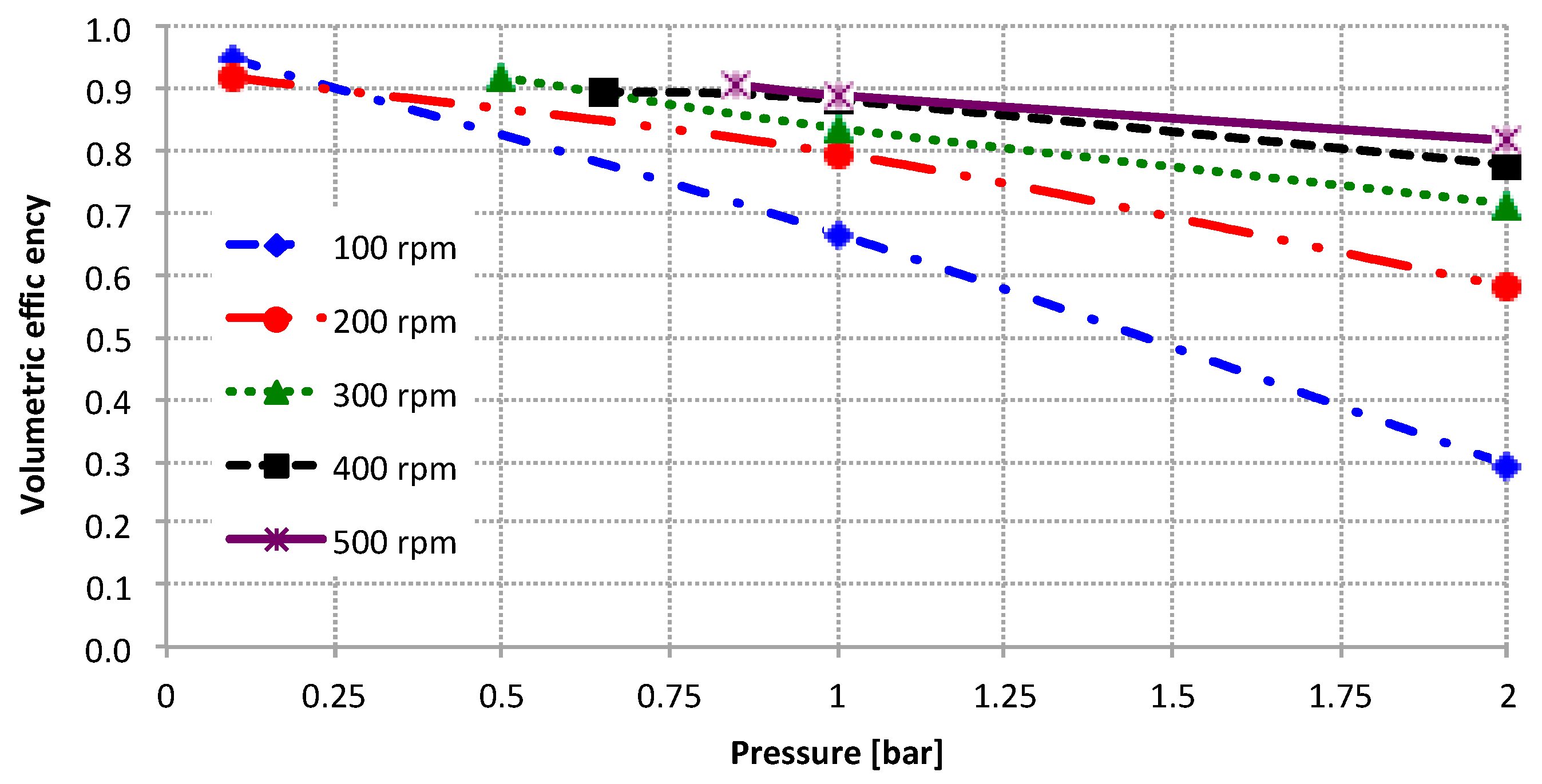
Figure 13 and
Figure 14 show the main experimental results of the GeroMAG pump. This shows a good quality of behavior in the steady-state flow rate—working pressure. In these first tests, to prove feasibility and technical performance, the rotational speed is limited to 500 rpm and the working pressure up to 2 bar.
With regard to volumetric efficiency, defined as the ratio between the measured and the theoretical flow rate (=cv·rpm), satisfactory indices are reached, all taking into account the low speed and working pressure settings. The volumetric efficiency is low at 100 rpm and 2 bar working pressure, predominantly owing to the leakage produced in the clearances of the trochoidal gear and housing. When the trochoidal gear tries to pump the fluid against 2 bar working pressure with such low rotational speed, the fluid is mostly kept inside the volume chambers. Moreover, this extremely low rotational speed does not help much with the viscous effect in the dragging velocity of the fluid in contact with the trochoidal gear. Another important effect at low rotational speed is the difficulty of achieving an effective hydrodynamic effect and full film lubrication at all times of operation. For all of these main reasons, the volumetric efficiency is around 30%. However, from 100 rpm to 200 rpm, the speed and volumetric efficiency are doubled, and an acceptable value of 82% for 500 rpm at 2 bar is reached.
The implications of these results lead to the conclusion that this innovative concept is achievable and works as a variable-flow hydraulic pump.
One of the main negative performance indicators is mechanical friction. On one hand, the ensemble must be tightly assembled to avoid leakage and increase volumetric efficiency, but on the other hand, it penalizes the frictional performance of the trochoidal gear set. Since in the GeroMAG pump architecture, the mechanical torque cannot be directly measured, the electrical power consumption (power source, drive, electronics and magnet brushless motor) is measured as a whole by using the power analyzer. In this first prototype, the measured electric power in dry conditions is 60 W and in the operating point of 500 rpm and 2 bar is 120 W with an overall efficiency around 11%.
5. Conclusions
The research presented in this paper is the technological development of a new concept of hydraulic machine: an innovative sealed, compact and non-shaft-driven gerotor pump with magnetically-driving outer rotor. The sealed, compact and non-mechanical drive shaft is reliable and results in a quiet and leakage-free unit. The external gear becomes the driving gear and the rotational movement is transmitted from the driving outer rotor to the driven internal gear. Afterwards, early in the design process, basic performance and dimensional requirements have become the key parameters that led to a custom trochoidal gear set, a new configuration of magnet brushless motor and a pioneering gerotor pump architecture: GeroMAG. The final stage of this design process has been the construction of the GeroMAG prototype.
The technology demonstration is carried out using this prototype with experimental work in a test bench. This novel configuration, as a variable flow pump, accomplishes a standard volumetric flow rate at low rotational speed with satisfactory volumetric efficiency. Experimental results prove feasibility as well as proof of concept. As a next step, the technological readiness has still to evolve to system development and field testing with wider operating conditions.
The GeroMAG concept is believed to lead to a cleaner and noiseless hydraulic technology, usable in a wider array of sectors. Moreover, if the configuration of the magnetically-driven outer rotor is also transferred to the internal gear, becoming likewise a magnetically-driven inner rotor, then the rotational movement could be performed with zero inter-tooth contact stress by controlling the electrical torque of both rotors. Hence, important advantages can be foreseen.
Future work will be directed towards miniaturizing the GeroMAG concept, progressing towards a mini georamas pump useful to life sciences, such as the pharmaceutical and medical sectors, and also the environmental area through direct dosing in exact quantities, maximum spraying and precision in their location over the plant (leaf, flower, and fruit) that could be used in a hydraulic robot visual serving system.


 ,
, 


