Predictive Control of Power Electronics Converters in Renewable Energy Systems


Department of Electrical Engineering, The Hong Kong Polytechnic University, Hong Kong, China
*
Author to whom correspondence should be addressed.
Energies 2017, 10(4), 515; https://doi.org/10.3390/en10040515
Submission received: 13 February 2017
/
Revised: 10 March 2017
/
Accepted: 7 April 2017
/
Published: 10 April 2017
(This article belongs to the Section F: Electrical Engineering)
Abstract
:Predictive control has attracted much attention and has been widely used in power electronics and electric drives. However, further developments for applications in the field of renewable energy systems are still under investigation. In this paper, the principles of predictive control are studied with a focus on model predictive control (MPC) and vector-sequence-based predictive control (VPC). Based on these techniques, two control strategies for flexible power supply are developed. They are implemented in the most promising renewable energy systems, namely solar photovoltaic (PV) systems and wind generators, respectively. The experimental results based on a laboratory prototype show that the active and reactive powers supplied by the PV and wind generator can be controlled flexibly with excellent steady-state and transient performance. As the penetration level of the renewable energy sources in electricity network continues to rise, predictive control tends to be an attractive and powerful technique for power electronics converters in renewable energy systems.
1. Introduction
In electric drives and AC/DC or DC/AC power conversion, a variety of power electronics converters have been utilized, and the corresponding control strategies have been an ongoing research subject over the last few decades. Recently, due to the sharp increase in the exploitation of renewable energy sources such as wind, solar photovoltaic (PV), and wave energy, more and more power electronics converters have been used to integrate the energy sources into the AC and/or DC common buses in a distributed generation (DG) system [1,2]. As the penetration and capacities of DG units increase, the power converters are required to operate more efficiently and effectively to maintain high power quality and dynamic stability. To fulfill these requirements, advanced control techniques have been intensively investigated in the last years.
Classic linear controllers, together with pulse width modulation (PWM) schemes and nonlinear controllers based on hysteresis comparators, have been the most widely studied and developed control strategies for power converters [3,4]. Later on more complex control techniques have been proposed as the computing power of microprocessors has increased dramatically. These include sliding mode control [5,6], fuzzy logic [7], genetic algorithms [8], and neural networks [9,10].
In the last few years, predictive control appears as an attractive alternative for power converters and has attracted much attention [11,12,13,14]. For example, predictive algorithms are used to control the current for a four-leg indirect matrix converter [12], the electromagnetic torque for machines [13], and the power for grid-connected two-level inverters [14]. The main characteristic of predictive control is the use of the system model for the prediction of the controlled variables. Next, predefined optimized criterion selects the appropriate control set. In fact, several kinds of control methods have been developed under the name of predictive control [15]. The most important types are model predictive control (MPC), vector-sequence-based predictive control (VPC), etc.
Although predictive control has been widely used in power electronics and electric drives, further developments are still under investigation for applications in the field of renewable energy systems, where DG sources are integrated to the local low voltage network through power converters. Taking the advantage of the excellent performance of the predictive control, this type of control approach is pointed to be a promising method in distributed generation and renewable energy systems. In [16], MPC technique is employed in a grid connected PV system. However, it is only implemented in the boost converter for maximum power point tracking (MPPT). Whereas, the main converter, i.e., the grid-connected DC/AC inverter, is not studied. In [17,18], predictive control is adopted to optimize the operational cost of microgrids with renewable energy sources and energy storage. The proposed predictive controller aims for system-level control using control horizons of several minutes or even hours, but it fails to consider the discrete-time models and behaviors of power converters that act as power electronic interface between the renewable energy sources and the grid.
This paper fills this important gap in the literature. Its contribution is to extend and explore the feasibility of predictive control and to advance this one step further by developing appropriate control strategies for renewable energy systems. Power converters will be modelled in the predictive controllers and the grid-connected operation will be focused. Specifically, a MPC scheme is developed for grid-connected solar PV systems, while a VPC approach is developed for doubly-fed induction generator (DFIG) wind systems. The importance of this paper can be summarized in ensuring more reliability for the operation of grid integration, exploiting the capability of flexible power regulation of grid-connected distributed generations, and providing better steady-state and dynamic response.
The rest of this paper is organized as follows. The operating principles of predictive control for power converters are reviewed in Section 2, where the most popular types, namely MPC and VPC are investigated. In Section 3, a MPC scheme is developed for grid-connected solar PV systems, while a VPC approach is developed for DFIG based wind energy systems. In Section 4, experimental results are provided to validate the effectiveness of the predictive control strategies, followed by the conclusion drawn in Section 5.
2. Predictive Control Theory
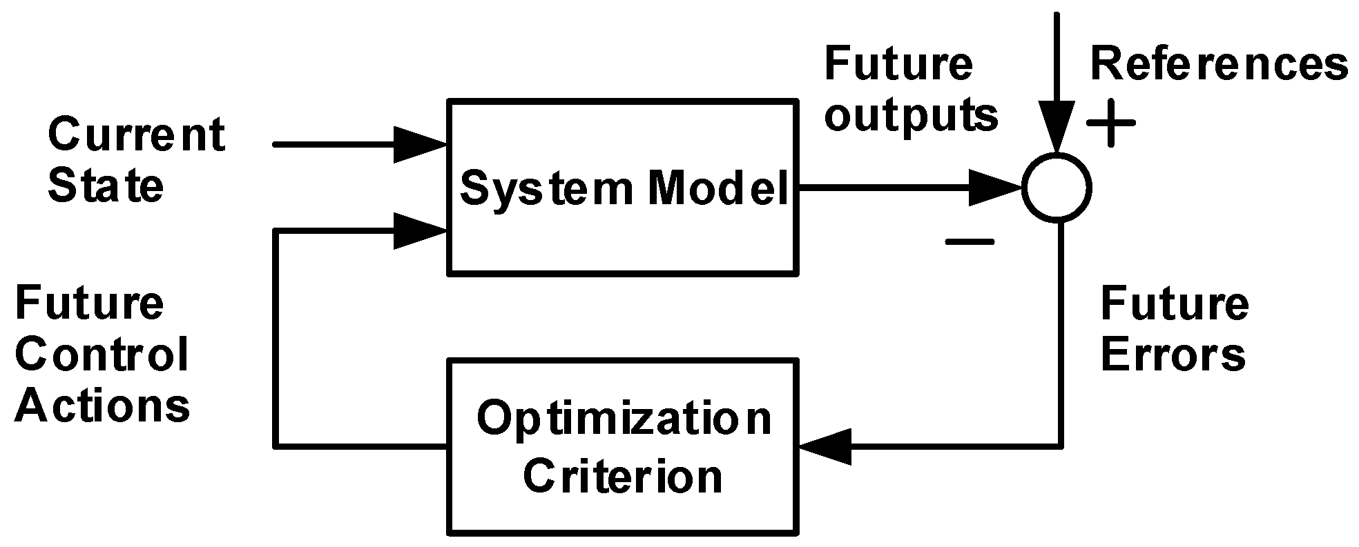
Predictive control refers to a very wide class of controllers that have been widely used in power converters. Figure 1 shows the architecture of a typical predictive controller. The system model can be expressed as a discrete-time state-space model, the output of which is determined by the input, the current state of the model, and the discrete interval. In this way, the future behavior of the system can be predicted over a time frame. By applying the optimal actuation that is obtained according to a predefined optimization criterion, the control problem can be defined as the determination of an appropriate control action that will force a generic system variable as close as possible to a desired reference value. In this paper, two typical predictive control methods are studied and applied, namely MPC and VPC.
2.1. Model Predictive Control (MPC)
In MPC, a system model is used to predict the behavior of the variables over a certain time horizon, and a cost function as the criterion is used to select the optimal switching states [11]. The principle of this control scheme is illustrated in Figure 2a. All the possible system transitions yp(tk+1) can be predicted using the measured value y(tk) at the control actions according to a prediction model {y(tk), N}. This prediction model is directly derived from the discrete-time model of the system, and it is various depending on the control objectives. Take N = 1 as an example, the system behavior at k + 1 instant can be predicted with the measured value y(tk) and n possible voltage vectors, resulting in n possible values yp1, yp2, …, ypn, as depicted in Figure 2b.
Next, a cost function will be formulated to evaluate the effectiveness of all the possible voltage vectors on the system performance. The voltage vector that minimizes the cost function will be chosen for the next sampling period. For example, if yp3 is closest to y*, the voltage vector producing yp3 will be selected to control the converter between k and k + 1 instants.
The advantage of MPC is that it allows the easy inclusion of system constraints, thus different control objectives can be flexibly taken in account in different applications. Another remarkable merit of MPC is the inclusion of nonlinearities, such as harmonic spectrum control and switching frequency reduction. The key is to choose the appropriate weighting factors to get a satisfactory tradeoff between the control objectives.
Notice that all the work mentioned above use a short horizon (usually equal to 1), which is called “Finite State Predictive Control”. There is another research area that considers longer control horizons (N > 1) such as power management of a hydrogen-based microgrid in [19], and PV plants with energy storage in [20]. For the sake of simplicity, N = 1 is adopted in this paper.
2.2. Vector-Sequence-Based Predictive Control (VPC)
This predictive control strategy selects an optimal set of concatenated voltage vectors in such a way that the controlled variables converge toward the reference values along a fixed predefined switching period [21]. Figure 3a depicts the basic principle of this method. In order to correct the error between the reference and the measured value, i.e., to enable the controlled variables to track the reference, an appropriate vector sequence is selected. After that, the optimized duration of each voltage vector applied within the control period is calculated according to some specified criteria. The criteria could be different. As illustrated in Figure 3b, it could be forcing y equal to y* at the end of the period, or making the mean value of y equal to y* over the entire period, or making the root-mean-square (RMS) value of y over one period to be minimal. The key of this predictive control method is to calculate the optimized durations (ti) of vectors using the measured y(k), the reference y*, and the derivatives σ1, σ2, and σ7. These derivatives indicate the effects of vector sequences on the controlled variables.
3. Application of Predictive Control in Renewable Energy Systems
In this Section, the predictive control approaches will be implemented in practical renewable energy systems. Because wind and solar PV are the two most promising and fastest growing renewable energy resources in the world [24,25], they will be used here as application examples to demonstrate the effectiveness of the predictive control strategies. The conventional three-phase two-level IGBT power converters are adopted.
3.1. MPC for PV Systems
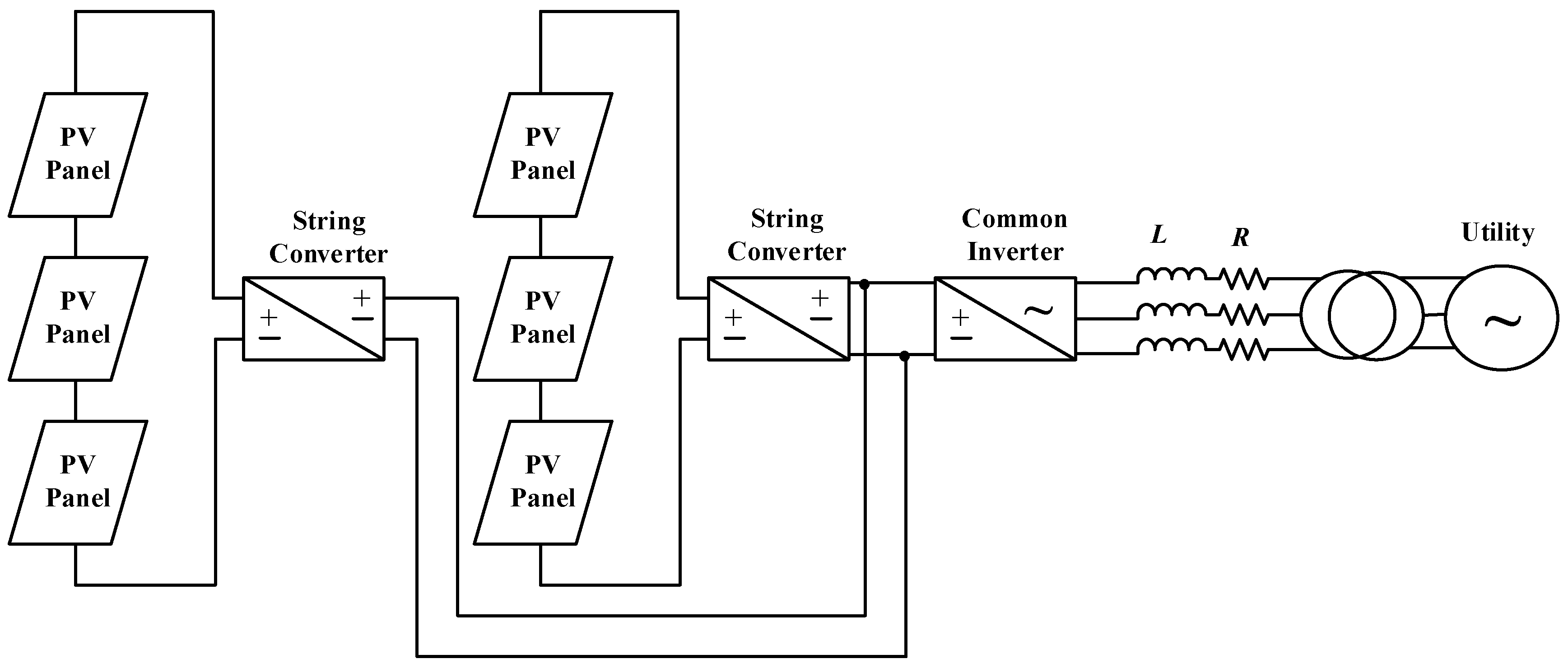
Solar energy is a renewable power source being widely exploited all around the world. PV technology involves converting solar energy directly into electrical power by means of solar cells, which are usually manufactured and combined into modules. For PV system, several useful topologies have been studied and applied [26]. Figure 4 shows a typical configuration of PV system where several strings are interfaced with their own DC-DC converter for voltage boosting and then connected to a common DC bus. After that, a common DC-AC inverter is used for grid interfacing. Usually the MPPT is implemented on the DC-DC converter, while the grid synchronization and power regulation are achieved by the grid-side inverter.
Since the MPPT techniques are mature and well developed, in this paper we concentrate on the control of the grid-side common inverter of the PV system (see Figure 4). Although many control schemes have been developed for grid-connected inverters, MPC is seldom mentioned in this application. Actually grid-connected PV systems should be controlled to regulate active and reactive powers flexibly for voltage support and power quality improvement [27]. In this sense, flexible power regulation capability for a DG unit becomes more and more significant. Here, a MPC strategy of grid-connected inverters for PV system is developed and implemented. For two-level inverters, there are eight possible voltage vectors generated by the inverter (six active vectors and two null vectors), and the α-β plane is divided into six sectors, as shown in Figure 5.
According to the equivalent circuit in Figure 4, the system mathematical model can be expressed as:
where Vi and Vg are the inverter output voltage vector and grid voltage vector, respectively; I the line current vector; L the filter inductance; R the filter resistance. The instantaneous active and reactive powers exchanged between the PV and the utility grid can be expressed as:
where α and β represent the real and imaginary components of the space vector expressed in the stationary frame. According to Equations (2) and (3), the active and reactive power derivatives can be calculated as:
Considering sinusoidal and balanced line voltage, one can obtain:
Thus, the inverter output active and reactive power derivatives can be obtained by substituting Equations (1), (6) and (7) into Equations (4) and (5) as:
Therefore, the predicted power at the end of the sampling period Ts can be expressed as:
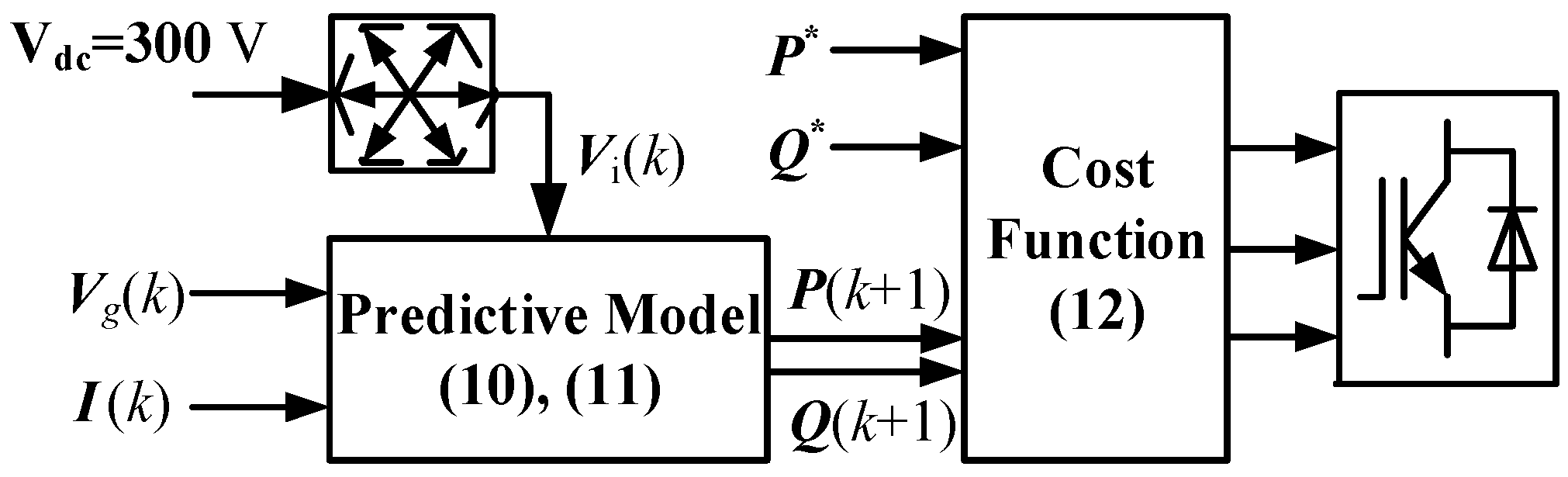
Now the predictive model has been obtained mathematically with Equations (10) and (11). Figure 6 depicts the block diagram of the proposed MPC strategy for grid-connected PV systems. After the power is predicted, the next step is to evaluate the effects of each voltage vector on active and reactive powers and then select the one producing the least power ripple according to a specific cost function. Here, the cost function is defined as follows considering the same weighting priority for P and Q:
Once the optimal voltage vector is determined, it will be applied during the next sampling period to control the inverter.
3.2. VPC for Wind Power Generation
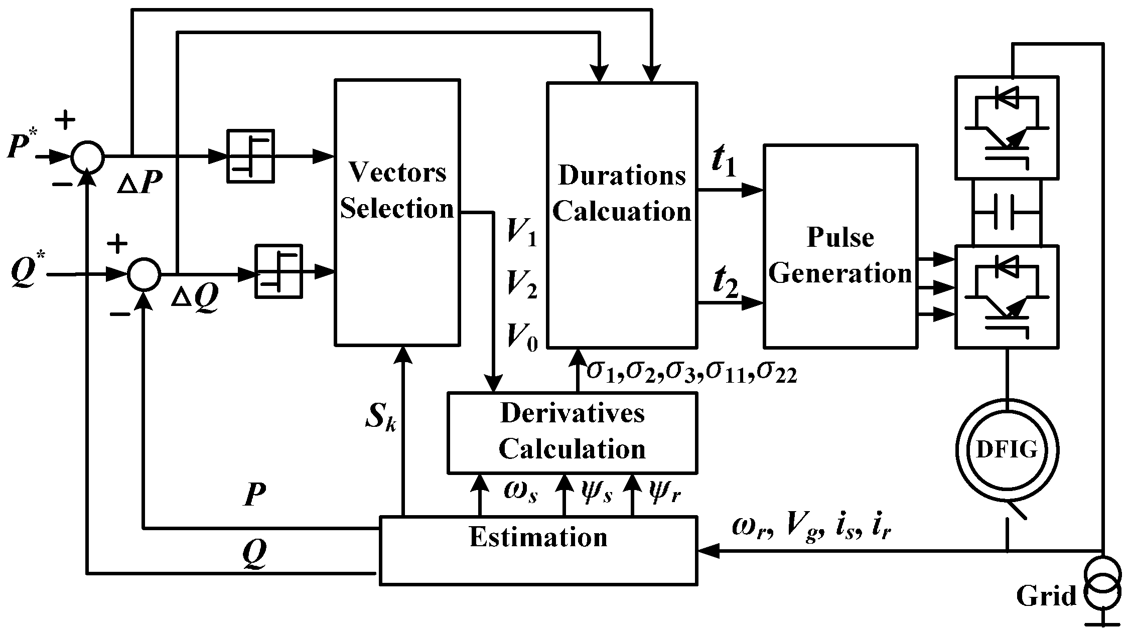
The DFIG and permanent magnet synchronous generator (PMSG) have dominated the global wind generator market. In this paper, the DFIG based wind system is studied. The DFIG has several advantages including maximum power capture over a wider speed range and decoupled active and reactive power control. It also allows the use of a partially rated converter which reduces the system cost [28]. Figure 7 shows the scheme of a DFIG based wind power generation system. The stator is directly connected to the grid, while a partial-scale power converter controls the rotor frequency and thus the rotor speed. Usually, the controller of the rotor side converter regulates the electromagnetic torque and supplies part of the reactive power to maintain the magnetization of the machine, while the controller of the grid side converter regulates the power factor and maintains the DC link voltage. In this paper, the control of rotor side converter is focused.
Here, the VPC will be adopted to control the rotor-side converter. As illustrated in Section 2, the objective of the VPC is to evaluate the effects of the possible vectors on the control variables, and then arrange an optimal set of concatenated voltage vectors, in such a way that the controlled objective converges toward the reference. Therefore, it is necessary to find out the effects of vectors on the wind power generator system. The mathematical equations for a DFIG are now well known but for completeness they can be expressed in the rotor frame using complex vectors as:
Voltage equations:
Flux equations:
Power equations:
The derivatives of the stator output active and reactive powers can be expressed as:
According to Equations (19) and (20), the power derivatives against rotor flux position in steady state for a DFIG wind generator can be obtained, as graphically depicted in Figure 8a. Now let us perform an analysis of the power derivatives. For instance, assuming that the rotor flux is located at the sector S3 while the active and reactive powers are both greater than the referenced values: V4 produces negative active power derivative (or “slope”) and negative reactive power slope; V5 produces negative active power slope and positive reactive power slope; while the null vectors (V0 and V7) generates very small power slopes. Based on this analysis, if the vector sequence V4–V5–V0 is applied, the active and reactive power can be well controlled, which is well illustrated in Figure 8b. In this way, the first two active vectors are used to correct the power errors, while the presence of the null vector is very useful at steady state because it produces relatively small power variation, resulting in the reduction of power ripples.
The vector selection scheme of VPC is summarized in Table 1. The vector sequence selection is related to the sign of the active power error ∆P because reactive power will be also controlled regardless of ∆Q sign, due to the fact that the first two active vectors produce opposite reactive power slopes, as illustrated in Figure 8a. Notice that the null vector should be chosen between V0 and V7 according to the principle of switching frequency reduction. After the three vectors are selected, the next step is to calculate the vector durations of t1 and t2, according to a specified criteria, as illustrated in Section 2. Here, t1 and t2 are computed by making the values of P and Q equal to their references at the end of each sampling period. The overall control strategy of VPC is illustrated in Figure 7. First, the wind generator status such as grid voltage, stator current, and rotor speed are measured. Based on these, the actual active and reactive powers will be calculated. Next, voltage vector sequences will be chosen from Table 1 according to the actual values of powers and the rotor flux position. Once the vector sequences are determined, the optimum duration of each voltage vector will be computed with the purpose of forcing the actual powers to track the references. Finally, the gate driving signals will be produced in PWM modulator.
4. Experimental Verification
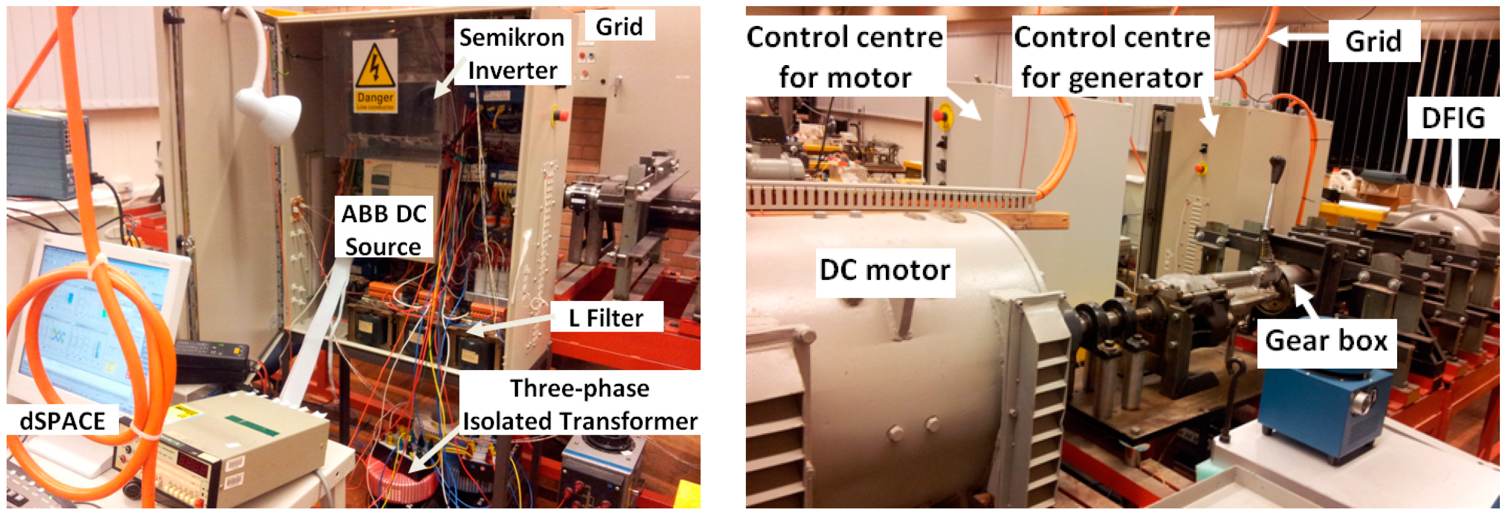
The experimental test has been carried out in a laboratory renewable energy test platform, as shown in Figure 9. In the wind system, a DC motor is used to simulate the wind turbine, which is connected to a 20 kW DFIG via a gear box. In the 10 kW PV system, an Asea Brown Boveri (ABB) DC source with 300 V DC output is use to simulate the PV panel output. The system parameters are listed in Table A1 in the Appendix A. Two dSPACE DS1104 PPC/DSP control boards (dSPACE GmbH, Paderborn, Germany) are employed to implement the real-time algorithm using C language for converter control. The system variables such as voltage, current and rotor position are sampled using the Control Desk. Since the conventional switching table based direct power control (SDPC) developed by Noguchi et al. [29] is a widely employed and accepted control strategy in the scientific community, it is used here as a benchmark reference for all the tests in the paper.
4.1. Experimental Results of MPC for PV System
In this test, the PV output is simulated by a DC voltage generated by an ABB rectifier. The proposed MPC scheme is implemented in the grid-connected inverter. The control objectives are the inverter output active and reactive powers, i.e., the power flows between the PV system and the grid. The parameters of the 10 kW PV system are shown in Table A2 in the Appendix A. The results in this test are presented using Per Unit. The powers supplied from the PV system to the grid and the inverter output currents are measured.
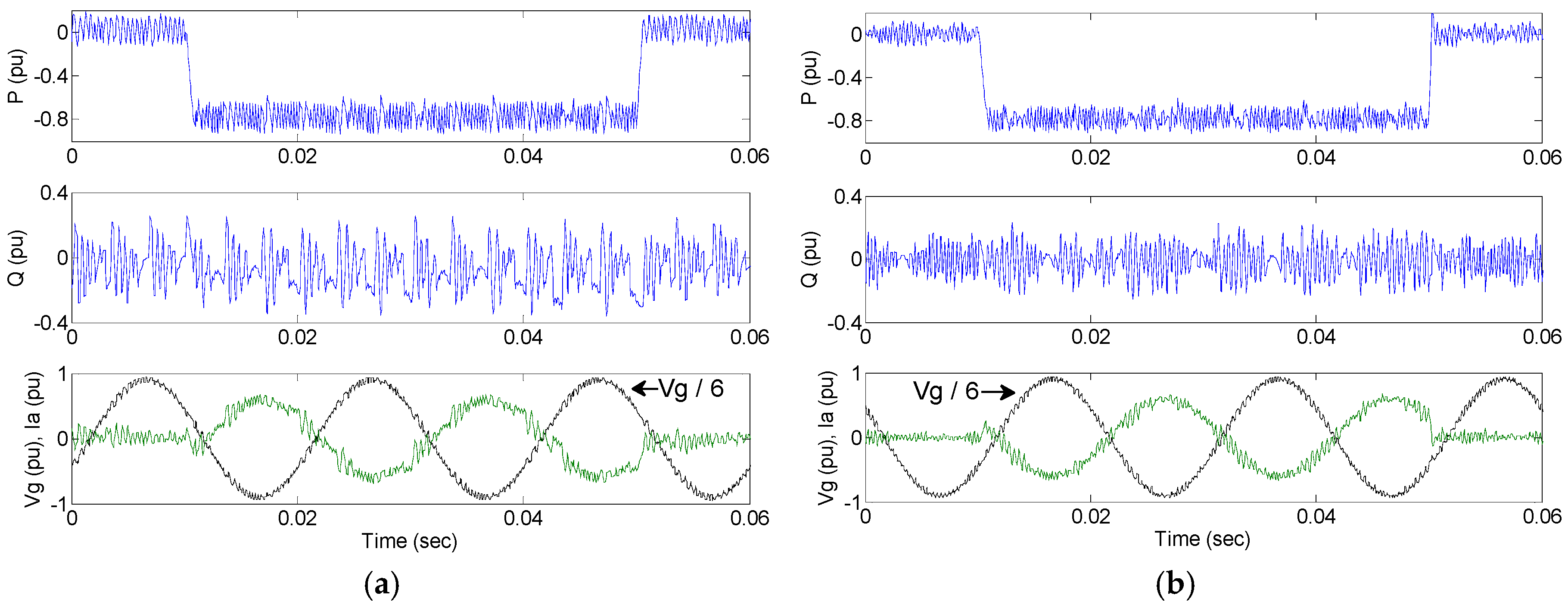
To evaluate the dynamic response of the proposed controller, the active power reference steps down from 0 pu to −0.8 pu and then steps up to 0 pu, while the reactive power reference is kept constant at zero. It is noted that the negative active power indicates that the PV system is feeding energy back to the utility grid. In other words, the current is flowing from the inverter to the grid side. Figure 10 shows the system dynamic response. It can be seen that the active powers are able to drop down to −0.8 pu at 0.01 s in a fast manner by using both SDPC scheme and the proposed MPC scheme. When the active power reference steps up to 0 pu at 0.05 s, it can be observed that the proposed MPC method can reach the new state slightly faster than conventional SDPC scheme, presenting excellent tracking ability. The main difference between two methods goes to the steady-state performance. It can be seen that the proposed MPC scheme results in less active and reactive power ripples in steady state.
To obtain a better comparison, Table 2 compares the steady-state performance in terms of the active power ripple Prip, reactive power ripple Qrip and the line current (i.e., the current injected from PV to the grid) total harmonic distortion (THD). The power ripples are calculated using standard deviation. Thanks to the vector selection according to an optimized cost function, the power injected to the main grid of the proposed MPC strategy is well controlled. In SDPC, the active power ripple and reactive power ripple are 88.53 W and 112.92 Var respectively, whereas Prip and Qrip are reduced to only 79.36 W and 82.65 Var respectively in the proposed MPC. Consequently, the line current THD is reduced from 8.27% to 6.14%.
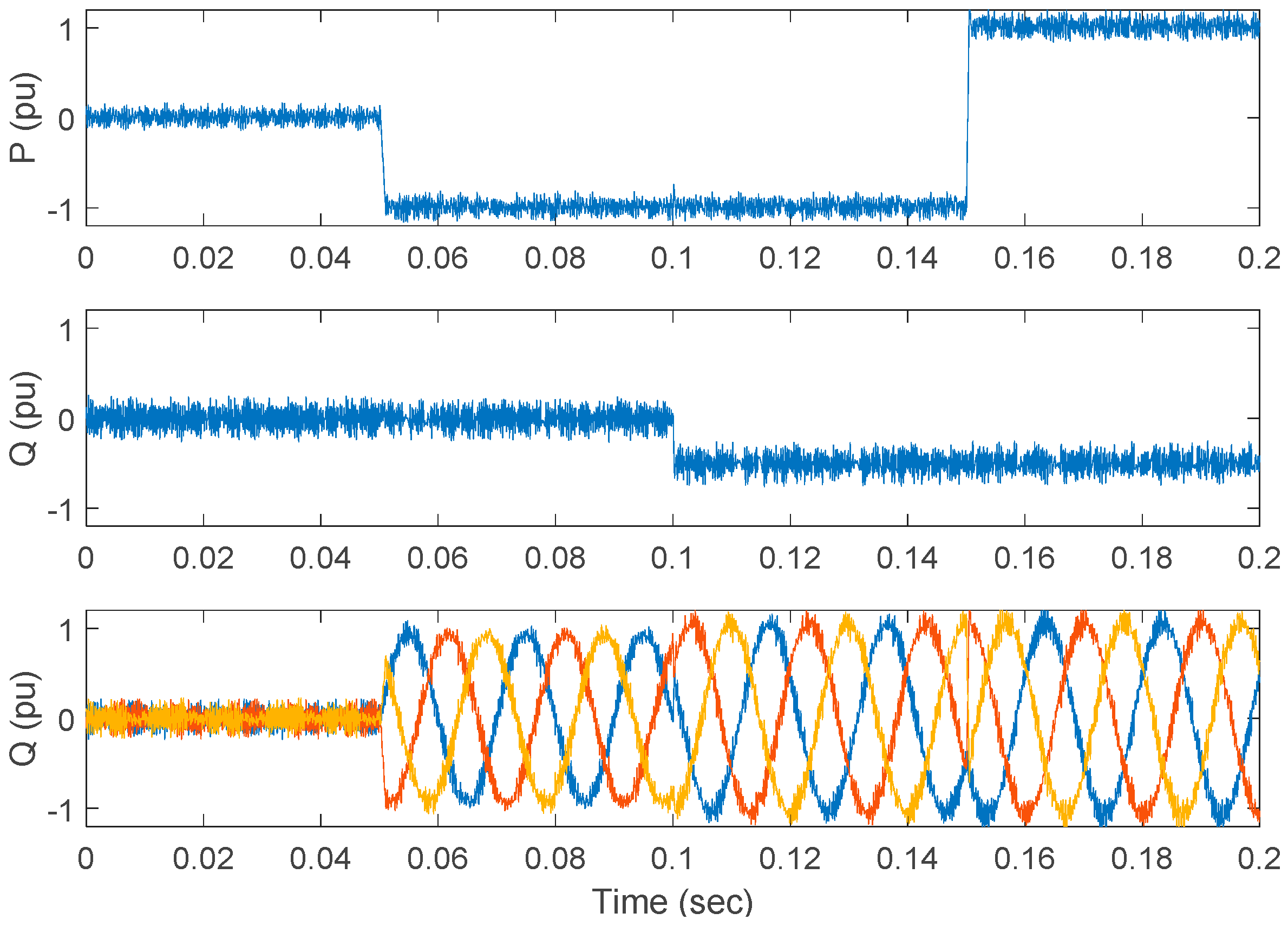
A comprehensive dynamic response of the MPC is also tested. A severe power variation was demanded, and the control strategy provokes that the system responds to that demand in a quick and safe manner. The active power reference stepped down to −1 pu at 0.05 s and then stepped up to 1 pu at 0.15 s, while the reactive power reference was changed to −0.5 pu at 0.1 s. Figure 11 presents the detailed dynamic response under such power variations condition. It can be seen that the new steady state can be reached in a fast manner without over currents. As explained before, optimum voltage vector is chosen in every sampling period to control the powers in MPC algorithm. Therefore, the active and reactive powers are able to track their references tightly.
4.2. Experimental Results of VPC for Wind System
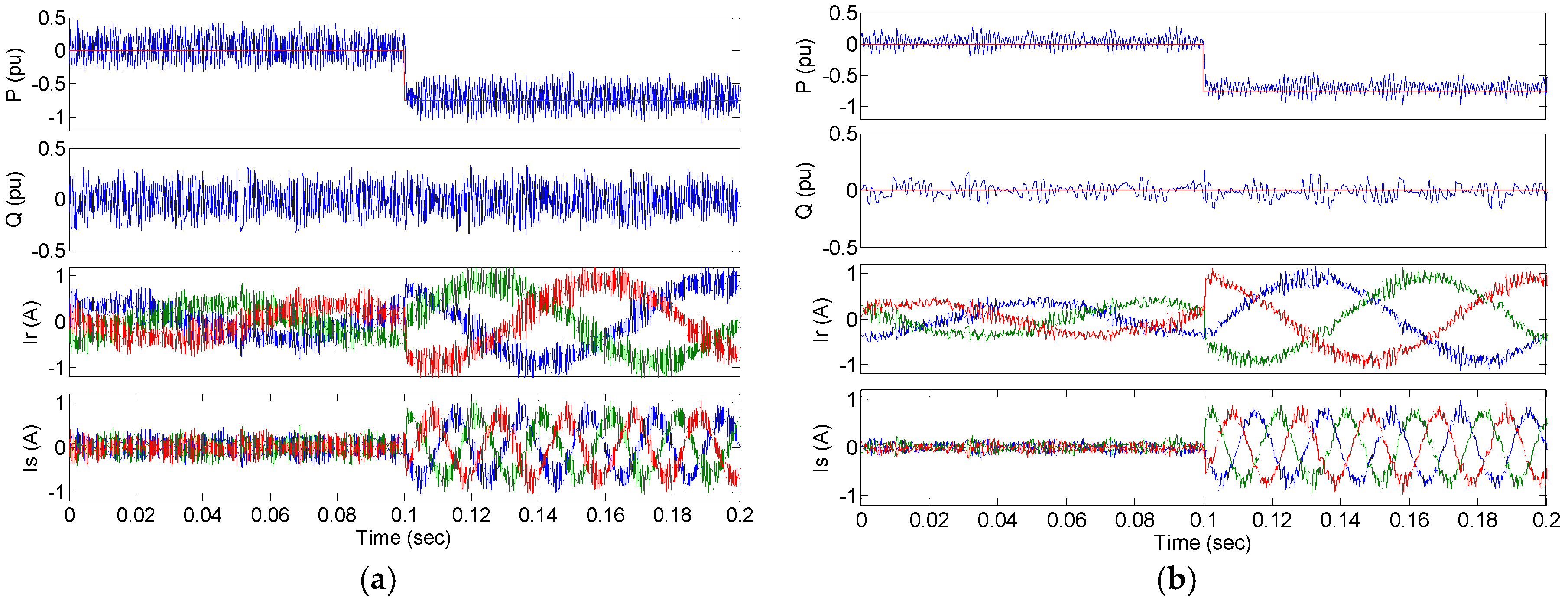
In the wind system test, the proposed VPC is implemented in the rotor-side converter. The dc-link voltage is established by the grid-side converter and it is out of the scope of this paper. The rotor speed is 1200 rpm, unless explicitly indicated otherwise. Similar to the test in the PV system, the control objectives are the output active and reactive powers at the stator of the wind generator, i.e., the powers exchanged between the wind generator and the grid. Once again, the active power reference features a stepped change from 0 pu to −0.75 pu, the transient response in powers and currents are measured and analyzed.
The experimental results are shown in Figure 12. From top to bottom, the waveforms are active power, reactive power, rotor currents, and stator currents, respectively. It can be seen that the active power using proposed VPC method can tracking the reference tightly and fast as well as SDPC approach. Besides, no dangerous overshoot currents in the rotor and the stator are observed during transient. It is noted that, due to the application of the proper vectors sequence at each sampling period, the power ripples using the proposed VPC strategy are reduced considerably, leading to an overall improvement of stator and rotor currents.
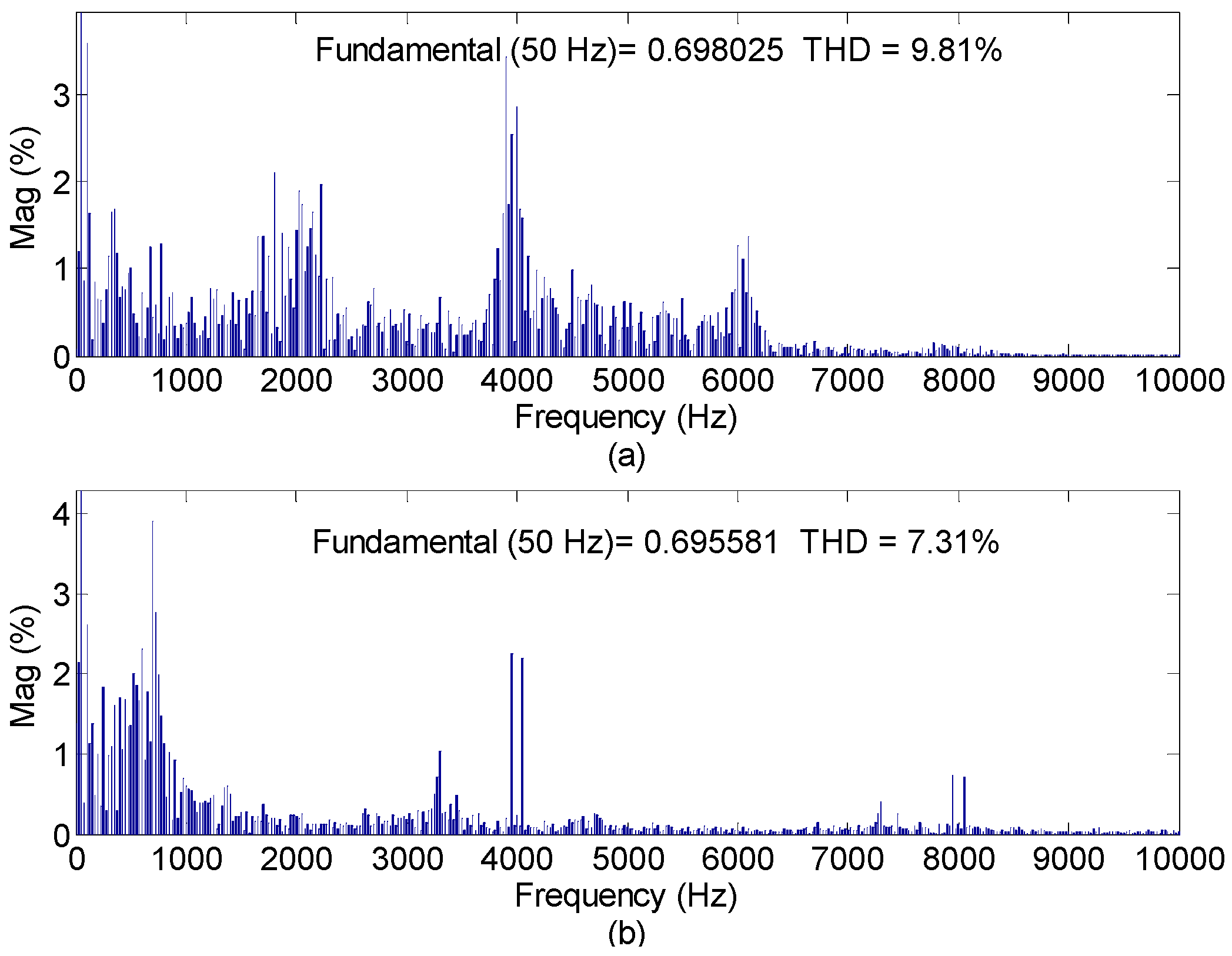
Figure 13 shows the stator current spectrum comparison. It can be observed that the stator current THD of VPC is 7.31% with the higher order harmonics appearing at 4 kHz frequency and its multiples. This is lower than 9.81% of SDPC with a broad harmonic spectrum. As explained in Section 3, two active vectors and one null vector are applied in every sampling period. And their applied durations are calculated by making the values of P and Q equal to their references at the end of each sampling period. Therefore, the active power and reactive power are better controlled than those in SDPC where only one vector is applied in every sampling period. As a result, an overall improvement of stator and rotor currents can be achieved in terms of THD. To obtain a clear comparison, the quantitative results using SDPC and VPC are tabulated in Table 3. It is seen that VPC can reduce the THD of the current and the power ripples considerably at an even lower switching frequency, compared to SDPC.
Another important issue needs to be mentioned is the power quality requirement for grid-connected energy sources. The International Electrotechnical Commission (IEC) initiated the standardization for wind turbines. The current standards for grid-connected PV include EN 61000-3-2, IEEE 1547 and the US National Electrical Code (NEC) 690, however, there is no specified maximum allowed reactive power [30] and they do specify the power factor constraints. For example, the allowable power factor of 1.0 ± 0.05 is the widely accepted requirement by most of the standards in industry. Thus, it is worth mentioning that nowadays grid regulators tend to allow wind turbines and PVs to actively regulate the reactive power injected into the grid to participate in grid stabilization and voltage support, considering the potential reactive capability of such grid-connected energy systems.
5. Conclusions
This paper has reviewed the most important types of predictive control approaches, namely model predictive control and vector-sequence-based predictive control. The basic principle of each control strategy has been comprehensively investigated. They are then employed in renewable energy systems such as wind power generation and PV power generation. Application examples have been described in details, and experimental verification is provided to demonstrate the feasibility and effectiveness of predictive control in laboratory prototypes.
Predictive control is an open control approach for new applications for renewable energy sources. With the increasing level of renewable energy sources penetration in existing power system, new challenges have been posted to the control of these distributed generation units (DGs). The DGs are not only controlled to injected power into the main grid, also required to participate in grid support by flexible power regulation. The authors believe that it is a tendency to apply predictive control renewable energy systems for its excellent steady-state and transient response.
Acknowledgments
This work is supported in part by The Hong Kong Polytechnic University under grant No. 1-ZE7J and G-YN27.
Author Contributions
Jiefeng Hu designed the controller, developed the laboratory prototype and conducted the test. Ka Wai Eric Cheng designed the filter parameters and conducted the results analysis.
Conflicts of Interest
The authors declare no conflict of interest
Appendix A

Table A1.
System Parameters of the Wind Power System.
| Symbol | Quantity | Value |
|---|---|---|
| Vrated,S | Rated stator voltage | 415 V (delta) |
| Vrated,r | Rated rotor voltage | 380 V (star) |
| Irated,S | Rated stator current | 38 A |
| Irated,r | Rated rotor current | 53 A |
| Vdc | DC-link voltage | 400 V |
| ωg | Grid angular frequency | 314.16 rad/s |
| Lm | Magnetizing inductance | 85.003 mH |
| Lσs | Stator leakage inductance | 2.426 mH |
| Lσr | Rotor leakage inductance (referred to stator) | 2.426 mH |
| Rs | Stator winding resistance | 0.207 Ω |
| Rr | Rotor winding resistance (referred to stator) | 0.218 Ω |
| p | Poles pairs | 2 |
Table A2.
System Parameters of the PV System.
| Symbol | Quantity | Value |
|---|---|---|
| Vdc | PV output | 300 V |
| Vg | Grid line-to-line voltage | 133 V rms |
| ωg | Grid angular frequency | 314.16 rad/s |
| L | Line Inductance | 4.5 mH |
| R | Line Resistance | 0.56 Ω |
References
- Blaabjerg, F.; Liserre, M.; Ma, K. Power electronics converters for wind turbine systems. IEEE Trans. Ind. Appl. 2012, 48, 708–719. [Google Scholar] [CrossRef]
- Guerrero, J.M.; Blaabjerg, F.; Zhelev, T.; Hemmes, K.; Monmasson, E.; Jemei, S.; Comech, M.P.; Granadino, R.; Frau, J.I. Distributed generation: Toward a new energy paradigm. IEEE Mag. Ind. Electron. 2010, 4, 52–64. [Google Scholar] [CrossRef]
- Holmes, G.; Lipo, T. Pulse Width Modulation for Power Converters: Principles and Practice; IEEE: Washington, DC, USA, 2003. [Google Scholar]
- Kazmierkowski, M.P.; Krishnan, R.; Blaabjerg, F. Control in Power Electronics Selected Problems; Academic Press: New York, NY, USA, 2002. [Google Scholar]
- Utkin, V.I. Sliding mode control design principles and applications to electric drives. IEEE Trans. Ind. Electron. 1993, 40, 23–36. [Google Scholar] [CrossRef]
- Raviraj, V.S.C.; Sen, P.C. Comparative study of proportional-integral, sliding mode, and fuzzy logic controllers for power converters. IEEE Trans. Ind. Appl. 1997, 33, 518–524. [Google Scholar] [CrossRef]
- Bouafia, A.; Krim, F.; Gaubert, J.P. Fuzzy-logic-based switching state selection for direct power control of three-phase PWM rectifier. IEEE Trans. Ind. Electron. 2009, 56, 1984–1992. [Google Scholar] [CrossRef]
- Ozpineci, B.; Tolbert, L.M.; Chiasson, J.N. Harmonic optimization of multilevel converters using genetic algorithms. IEEE Trans. Power Electron. Lett. 2005, 3, 92–95. [Google Scholar] [CrossRef]
- Leyva, R.; Martinez-Salamero, L.; Jammes, B.; Marpinard, J.C.; Guinjoan, F. Identification and control of power converters by means of neural networks. IEEE Trans. Circuits Syst. 1997, 44, 735–742. [Google Scholar] [CrossRef]
- Veerachary, M.; Senjyu, T.; Uezato, K. Neural-network-based maximum-power-point tracking of coupled-inductor interleaved-boost-converter-supplied PV system using fuzzy controller. IEEE Trans. Ind. Electron. 2003, 50, 749–758. [Google Scholar] [CrossRef]
- Rodriguez, J.; Cortes, P. Predictive Control of Power Converters and Electrical Drives; Wiley-IEEE: Hoboken, NJ, USA, 2012. [Google Scholar]
- Garcia, C.F.; Rivera, M.E.; Rodríguez, J.R.; Wheeler, P.W.; Peña, R.S. Predictive current control with instantaneous reactive power minimization for four-leg indirect matrix converter. IEEE Trans. Ind. Electron. 2017, 64, 922–929. [Google Scholar] [CrossRef]
- Kouro, S.; Cortes, P.; Vargas, R.; Ammann, U.; Rodriguez, J. Model predictive control—A simple and powerful method to control power converters. IEEE Trans. Ind. Electron. 2009, 56, 1826–1838. [Google Scholar] [CrossRef]
- Vazquez, S.; Leon, J.I.; Franquelo, L.G.; Rodriguez, J.; Young, H.A.; Marquez, A.; Zanchetta, P. Model predictive control: A review of its applications in power electronics. IEEE Ind. Electron. Mag. 2014, 8, 16–31. [Google Scholar] [CrossRef]
- Cortes, P.; Kazmierkowski, M.P.; Kennel, R.M.; Quevedo, D.E.; Rodriguez, J. Predictive control in power electronics and drives. IEEE Trans. Ind. Electron. 2008, 55, 4312–4324. [Google Scholar] [CrossRef]
- Rodriguez, J.; Kazmierkowski, M.P.; Espinoza, J.R.; Zanchetta, P.; Abu-Rub, H.; Young, H.A.; Rojas, C.A. State of the art of finite control set model predictive control in power electronics. IEEE Trans. Ind. Inf. 2013, 9, 1003–1016. [Google Scholar] [CrossRef]
- Salazar, J.; Valverde, L.; Tadeo, F. Predictive control of a renewable energy microgrid with operational cost optimization. In Proceedings of the 39th Annual Conference of the IEEE Industrial Electronics Society, Vienna, Austria, 10–13 November 2013; pp. 7950–7955. [Google Scholar]
- Zhang, X.; Bao, J.; Wang, R.; Zheng, C.; Skyllas-kazacos, M. Dissipativity based distributed economic model predictive control for residential microgrids with renewable energy generation and battery energy storage. Renew. Energy 2017, 100, 18–34. [Google Scholar] [CrossRef]
- Valverde, S.; Bordons, C.; Rosa, F. Power management using model predictive control in a hydrogen-based microgrid. In Proceedings of the 38th Annual Conference of IEEE Industrial Electronics (IECON 2012), Montreal, QC, Canada, 25–28 October 2012; pp. 5653–5660. [Google Scholar]
- Perez, L.; Beltran, H.; Aparicio, N.; Rodriguez, P. Predictive power control for PV plants with energy storage. IEEE Trans. Sustain. Energy 2013, 4, 482–490. [Google Scholar] [CrossRef]
- Hu, J.; Zhu, J.; Zhang, Y.; Platt, G.; Ma, Q.; Dorrell, D.G. Predictive direct virtual torque and power control of doubly fed induction generators for fast and smooth grid synchronization and flexible power regulation. IEEE Trans. Power Electron. 2008, 28, 3182–3194. [Google Scholar] [CrossRef]
- Song, Z.; Tian, Y.; Chen, Z.; Hu, Y. Enhanced predictive current control of three-phase grid-tied reversible converters with improved switching patterns. Energies 2016, 9, 41. [Google Scholar] [CrossRef]
- Abad, G.; Rodriguez, M.A.; Poza, J. Two-level VSC based predictive direct torque control of the doubly fed induction machine with reduced torque and flux ripples at low constant switching frequency. IEEE Trans. Power Electron. 2008, 23, 1050–1061. [Google Scholar] [CrossRef]
- Saygin, D.; Kempener, R.; Wagner, N.; Ayuso, M.; Gielen, D. The implications for renewable energy innovation of doubling the share of renewables in the global energy mix between 2010 and 2030. Energies 2015, 8, 5828–5865. [Google Scholar] [CrossRef]
- Blaabjerg, F.; Ma, K. Future on power electronics for wind turbine systems. IEEE J. Emerg. Sel. Top. Power Electron. 2013, 1, 139–152. [Google Scholar] [CrossRef]
- Kramer, W.; Chakraborty, S.; Kroposki, B.; Thomas, H. Advanced Power Electronic Interfaces for Distributed Energy Systems—Part1: Systems and Topologies; National Renewable Energy Laboratory: Golden, CO, USA, 2008.
- Wang, F.; Duarte, J.L.; Hendrix, M.A.M. Grid-interfacing converter systems with enhanced voltage quality for microgrid application—Concept and implementation. IEEE Trans. Power Electron. 2011, 26, 3501–3513. [Google Scholar] [CrossRef]
- Tanvir, A.A.; Merabet, A.; Beguenane, R. Real-time control of active and reactive power for doubly fed induction generator (DFIG)-based wind energy conversion system. Energies 2015, 8, 10389–10408. [Google Scholar] [CrossRef]
- Noguchi, T.; Tomiki, H.; Kondo, S.; Takahashi, I. Direct power control of PWM converter without power-source voltage sensors. IEEE Trans. Ind. Appl. 1998, 34, 473–479. [Google Scholar] [CrossRef]
- Carrasco, J.M.; Franquelo, L.G.; Bialasiewicz, J.T.; Galvan, E.; Guisado, R.C.P.; Prats, M.A.M.; León, J.I.; Moreno-Alfonso, N. Power-electronic systems for the grid integration of renewable energy sources: A survey. IEEE Trans. Ind. Electron. 2006, 53, 1002–1016. [Google Scholar] [CrossRef]
Figure 1.
Basic principle of predictive control.

Figure 2.
Illustration of MPC operation, (a) block diagram of MPC; (b) vectors evaluation and selection.
Figure 2.
Illustration of MPC operation, (a) block diagram of MPC; (b) vectors evaluation and selection.
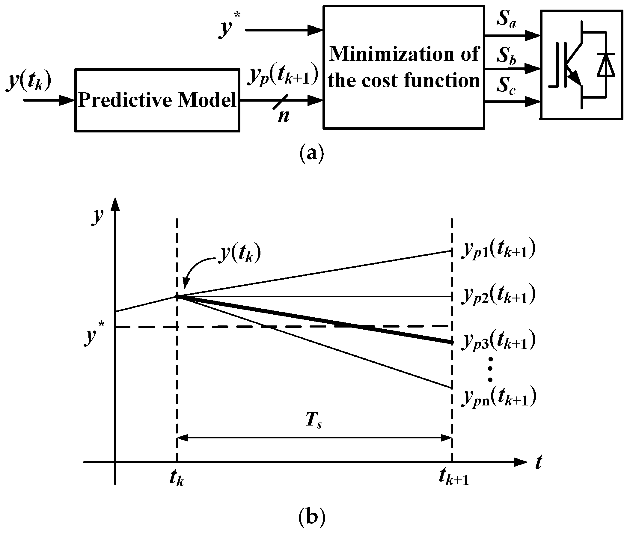
Figure 3.
Illustration of VPC operation, (a) block diagram of VPC; (b) vectors evaluation and selection.
Figure 3.
Illustration of VPC operation, (a) block diagram of VPC; (b) vectors evaluation and selection.

Figure 4.
A typical configuration of PV system.

Figure 5.
Possible voltage vectors generated by the inverter and sector division.
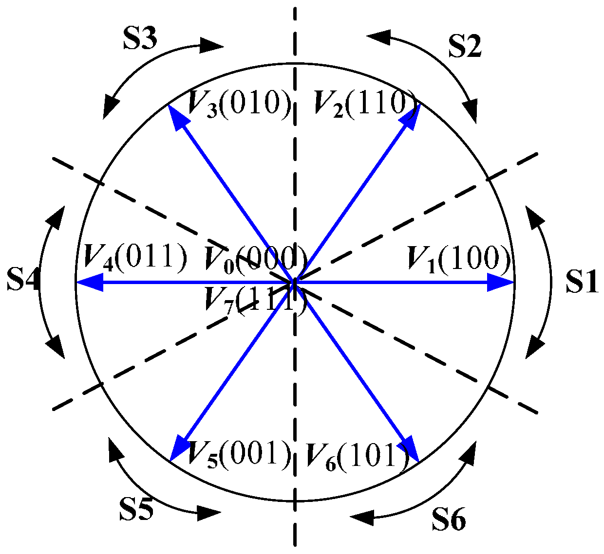
Figure 6.
Block diagram of MPC strategy of PV systems.

Figure 7.
DFIG based wind system structure and the block diagram of the proposed VPC scheme.

Figure 8.
Effects of voltage vectors on DFIG stator output powers, (a) active and reactive power derivatives against rotor flux position; (b) power waveforms of three-vector-based strategy.
Figure 8.
Effects of voltage vectors on DFIG stator output powers, (a) active and reactive power derivatives against rotor flux position; (b) power waveforms of three-vector-based strategy.
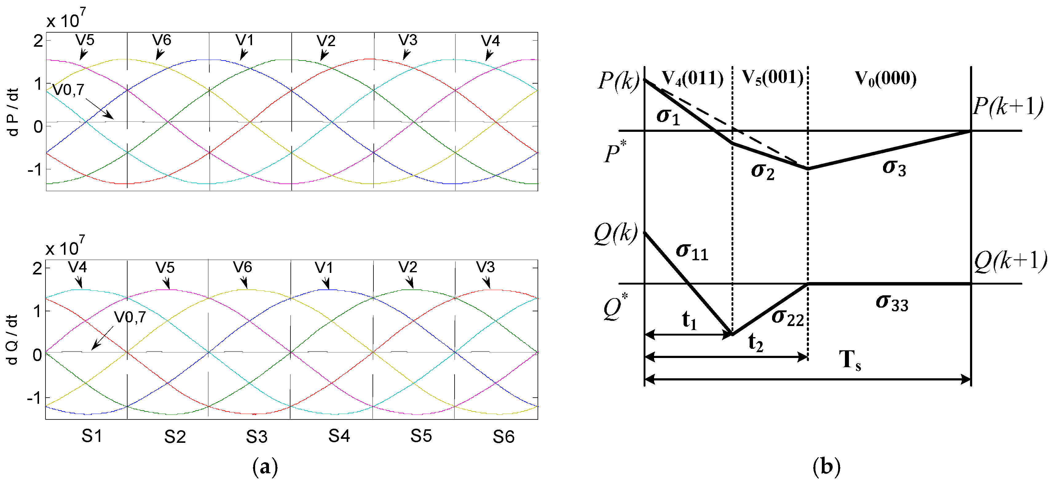
Figure 9.
Laboratory renewable energy test platform. (Left) Solar PV system; (Right) wind system.

Figure 10.
Experimental results of solar power generation, (a) SDPC scheme; (b) proposed MPC scheme.
Figure 10.
Experimental results of solar power generation, (a) SDPC scheme; (b) proposed MPC scheme.

Figure 11.
Dynamic performance of the proposed MPC scheme.

Figure 12.
Experimental results of wind power generation, P* steps down to −0.75 pu at 0.1 s, (a) SDPC with fs = 10 kHz and fsw = 3.89 kHz; (b) VPC with fs = 4 kHz and fsw = 2.17 kHz.
Figure 12.
Experimental results of wind power generation, P* steps down to −0.75 pu at 0.1 s, (a) SDPC with fs = 10 kHz and fsw = 3.89 kHz; (b) VPC with fs = 4 kHz and fsw = 2.17 kHz.

Figure 13.
Stator current spectrum analysis. (a) SDPC; (b) VPC.

Table 1.
Vector selection strategy.
| ∆P (P*–P) | Vector Sequence (k is the Sector Number) |
|---|---|
| >0 | Vk−1–Vk−2–V0,7 |
| <0 | Vk+1–Vk+2–V0,7 |
Table 2.
Quantitative comparison of SDPC scheme and proposed MPC scheme.
| Strategy | fs (kHz) | fsw (kHz) | Prip (W) | Qrip (Var) | THD (%) |
|---|---|---|---|---|---|
| SDPC | 20 | 3.32 | 88.53 | 112.92 | 8.27 |
| MPC | 20 | 3.39 | 79.36 | 82.65 | 6.14 |
Table 3.
Quantitative comparison of SDPC scheme and proposed VPC scheme.
| Strategy | fs (kHz) | fsw (kHz) | Prip (W) | Qrip (Var) | THD (%) |
|---|---|---|---|---|---|
| SDPC | 10 | 3.89 | 790.6 | 659.4 | 9.81 |
| VDPC | 4 | 2.17 | 434.3 | 488.0 | 7.31 |
© 2017 by the authors. Licensee MDPI, Basel, Switzerland. This article is an open access article distributed under the terms and conditions of the Creative Commons Attribution (CC BY) license (http://creativecommons.org/licenses/by/4.0/).
Share and Cite
MDPI and ACS Style
Hu, J.; Cheng, K.W.E. Predictive Control of Power Electronics Converters in Renewable Energy Systems. Energies 2017, 10, 515. https://doi.org/10.3390/en10040515
AMA Style
Hu J, Cheng KWE. Predictive Control of Power Electronics Converters in Renewable Energy Systems. Energies. 2017; 10(4):515. https://doi.org/10.3390/en10040515
Chicago/Turabian StyleHu, Jiefeng, and Ka Wai Eric Cheng. 2017. "Predictive Control of Power Electronics Converters in Renewable Energy Systems" Energies 10, no. 4: 515. https://doi.org/10.3390/en10040515
Note that from the first issue of 2016, this journal uses article numbers instead of page numbers. See further details here.